


PARTS AND OPERATION MANUAL
Table of Contents
MQ POWER
DUELWELDTM
WELDER/AC GENERATOR
MODEL BLW-400SSW
© COPYRIGHT 2001, MULTIQUIP INC.
S/N 5308765~
Revision #1(06/15/01)
MULTIQUIP INC. |
PARTS DEPARTMENT: |
18910 WILMINGTON AVE. |
800-427-1244 |
CARSON, CALIFORNIA 90746 |
FAX: 800-672-7877 |
310-537-3700 |
SERVICE DEPARTMENT: |
800-421-1244 |
800-835-2551 |
FAX:310-537-3927 |
FAX:310-638-8046 |
E-mail:mq@multiquip.com • www:multiquip.com
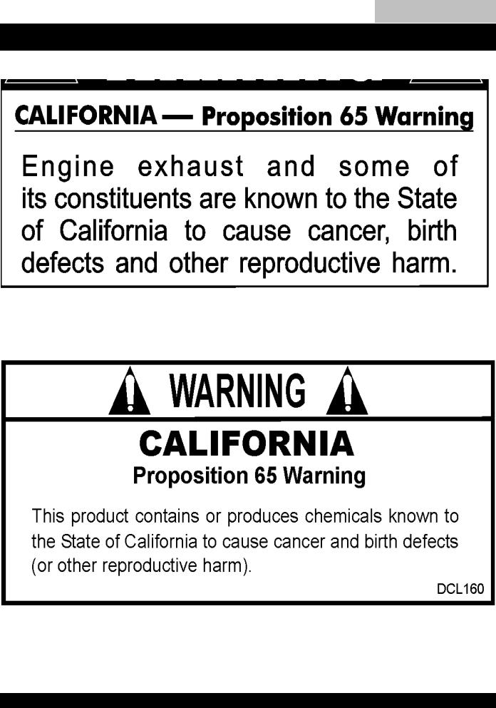
Table of Contents
PAGE 2 — BLW-400SSW- WELDER/AC GENERATOR — PARTS & OPERATION MANUAL — REV. #1 (06/15/01)

Table of Contents
HERE'S HOW TO GET HELP
PLEASE HAVE THE MODEL AND SERIAL NUMBER ON-HAND WHEN CALLING
PARTS DEPARTMENT
800/427-1244 or 310/537-3700 FAX: 800/672-7877 or 310/637-3284
SERVICE DEPARTMENT
800/835-2551 or 310/537-3700 FAX: 310/638-8046
WARRANTY DEPARTMENT
800/835-2551 or 310/537-3700 FAX: 310/638-8046
MAIN
800/421-1244 or 310/537-3700 FAX: 310/537-3927
BLW-400SSW-WELDER/AC GENERATOR— PARTS & OPERATION MANUAL— REV. #1 (06/15/01) — PAGE 3

TABLE OF CONTENTS
Here’s How to Get Help........................................... |
3 |
Parts Ordering Procedures ..................................... |
5 |
Rules for Safe Operation ..................................... |
6-7 |
Operation and Safety Decals ............................... |
8-9 |
Specifications ........................................................ |
10 |
General Information .............................................. |
11 |
Dimensions ........................................................... |
12 |
Trailer Safety Guidelines .................................. |
13-18 |
Trailer Wiring Diagram........................................... |
19 |
Electrical Brake Troubleshooting ........................... |
20 |
Towing Safety Guidelines ...................................... |
21 |
Controls and Indicators .................................... |
22-23 |
Output Terminal Overview ................................ |
24-25 |
Installation ............................................................. |
26 |
Pre-Set Up ....................................................... |
27-29 |
Load Application ................................................... |
30 |
Welder Operating Instructions ......................... |
31-32 |
Welder/AC Generator Start-up Instructions..... |
33-34 |
Shutdown Instructions........................................... |
35 |
Maintenance ......................................................... |
36 |
Preparation for Long Term Storage ...................... |
37 |
Generator Wiring Diagram ............................... |
38-39 |
Engine Wiring Diagrams................................... |
40-41 |
Engine Troubleshooting.................................... |
42-44 |
Welding Troubleshooting ....................................... |
45 |
Explanation of Codes in Remarks Section............ |
46 |
Suggested Spare Parts List .................................. |
47 |
BLW-400SSW WELDER/ |
|
AC GENERATOR |
|
Generator Assembly ........................................ |
48-51 |
Control Box Assembly ...................................... |
52-55 |
Control Parts Assembly, part 1 ........................ |
56-57 |
Control Parts Assembly, part 2 ........................ |
58-59 |
Engine and Radiator Assembly........................ |
60-61 |
Battery Assembly ............................................. |
62-63 |
Muffler Assembly ............................................. |
64-65 |
Fuel Tank Assembly ......................................... |
66-67 |
Enclosure Assembly......................................... |
68-69 |
Rubber Seals Assembly ................................... |
70-71 |
Decal Assembly ............................................... |
72-73 |
KUBOTA V1205B ENGINE
Crankcase Assembly ....................................... |
74-75 |
Oil Pan Assembly ............................................. |
76-77 |
Cylinder Head Assembly .................................. |
78-79 |
Gear Case Assembly ....................................... |
80-81 |
Main Bearing Case Assembly .......................... |
82-83 |
Head Cover Assembly ..................................... |
84-85 |
Inlet Manifold Assembly ................................... |
86-87 |
Exhaust Manifold Assembly ............................. |
88-89 |
Rocker Arm Valve Assembly ............................ |
90-91 |
Camshaft Assembly ......................................... |
92-93 |
Piston Crankshaft Assembly ............................ |
94-95 |
Flywheel Assembly .......................................... |
96-97 |
Injection Pump Assembly ................................. |
98-99 |
Fuel Camshaft Assembly ............................. |
100-101 |
Nozzle Holder Assembly .............................. |
102-103 |
Idling Apparatus Assembly .......................... |
104-105 |
Governor Assembly ..................................... |
106-107 |
Speed Control Plate Assembly .................... |
108-109 |
Dynamo Assembly ....................................... |
110-111 |
Water Flange Assembly ............................... |
112-113 |
Water Pump Assembly ................................. |
114-115 |
Fan Assembly............................................... |
116-117 |
Radiator Assembly ....................................... |
118-119 |
Air Cleaner Assembly................................... |
120-121 |
Fuel Filter Component Assembly................. |
122-123 |
Dynamo Component Assembly ................... |
124-125 |
Starter Component Assembly...................... |
126-127 |
Nozzle Holder Component Assembly .......... |
128-129 |
Injection Pump Component Assembly ......... |
130-133 |
Accessories .................................................. |
134-135 |
Terms and Conditions - Sales ............................. |
136 |
NOTE
Specification and part number are subject to change without notice.
PAGE 4 — BLW-400SSW- WELDER/AC GENERATOR — PARTS & OPERATION MANUAL — REV. #1 (06/15/01)
Table of Contents
PARTS ORDERING PROCEDURES
■Dealer account number
■Dealer name and address
■Shipping address (if different than billing address)
■Return fax number
■Applicable model number
■Quantity, part number and description of each part
■Specify preferred method of shipment:
•
•
•
•
•
•
UPS Ground
UPS Second Day or Third Day* UPS Next Day*
Federal Express Priority One (please provide us with your Federal Express account number)*
Airborne Express*
Truck or parcel post
*Normally shipped the same day the order is received, if prior to 2PM west coast time.
Earn Extra Discounts when you order by FAX!
All parts orders which include complete part numbers and are received by fax qualify for the following extra discounts:
Number of |
|
line items ordered |
Additional Discount |
1-9 items |
3% |
10+ items** |
5% |
Get special freight allowances when you order 10 or more line items via FAX!**
■UPS Ground Service at no charge for freight
■PS Third Day Service at one-half of actual freight cost
No other allowances on freight shipped by any other carrier.
**Common nuts, bolts and washers (all items under $1.00 list price) do not count towards the 10+ line items.
*DISCOUNTS ARE SUBJECT TO CHANGE*
Fax order discount and UPS special programs revised June 1, 1995
Extra |
Fax |
Discount |
||
USA |
||||
|
||||
for |
Domestic |
|||
|
|
Only |
||
|
|
|
||
|
Dealers |
|||
|
UPS |
|
Special |
||
|
ed orders |
only |
For |
fax |
|
|
|
|
Now! Direct TOLL-FREE access to our Parts Department!
Toll-free nationwide:
800-421-1244 Toll-free FAX:
800/6-PARTS-7 • 800-672-7877
BLW-400SSW-WELDER/AC GENERATOR— PARTS & OPERATION MANUAL— REV. #1 (06/15/01) — PAGE 5
CAUTION:
Failure to follow instructions in this manual may lead to serious injury or even death! This equipment is to be operated by trained and qualified personnel only!This equipment is for industrial use only.
The following safety guidelines should always be used when operating the BLW-400SSW Welder/AC Generator:
GENERAL SAFETY
■DONOToperateorservicethisequipmentbefore readingthisentiremanual.
■This equipment should not be operated by persons under 18 years of age.
■NEVER operate this equipment without proper protective clothing, welding shield, ventilator, steel-toed boots and other protective devices required by the job.
■NEVER operate this equipment when not feeling well due to fatigue, illness or taking medicine.
■NEVER operate this equipment under the influence or drugs or alcohol.
■NEVER use accessories or attachments, which are not recommended by MQ Power for this equipment. Damage to the equipment and/or injury to user may result.
■Manufacture does not assume responsibility for any accident due to equipment modifications.
■Whenever necessary, replace nameplate, operation and safety decals when they become difficult read.
■Always check the machine for loosened threads or bolts before starting.
Table of Contents
RULES FOR SAFE OPERATION
■NEVER touch the hot exhaust manifold, muffler or cylinder. Allow these parts to cool before servicing engine or welder/AC generator.
■HighTemperatures – Allow the engine to cool before adding fuel or performing service and maintenance functions. Contact with hot components can cause serious burns.
■The engine of this welder/AC generator requires an adequate free flow of cooling air. Never operate the welder/AC generator in any enclosed or narrow area where free flow of the air is restricted. If the air flow is restricted it will cause serious damage to the welder/AC generator engine and may cause injury to people.The engine gives off DEADLY carbon monoxide gas.
CAUTION:
Always refuel in a well-ventilated area, away from sparks and open flames.
Always use extreme caution when working with flammable liquids. When refueling, stop the engine and allow it to cool. DO NOT smoke around or near the machine. Fire or explosion could result from fuel vapors, or if
fuel is spilled on a hot engine.
■ NEVER operate the welder/AC generator in an explosive atmosphere or near combustible materials. An explosion or fire could result causing severe bodily harm or even death.
■ Topping-off to filler port is dangerous, as it tends to spill fuel.
PAGE 6 — BLW-400SSW- WELDER/AC GENERATOR — PARTS & OPERATION MANUAL — REV. #1 (06/15/01)

CAUTION:
This welder/AC generator is a source of providing LETHAL high voltages. Never permit unqualified personnel-especially children to operate the welder/AC generator.
■This welder/AC generator is equipped with a ground terminal for your protection. Always complete the grounding path from the welder/AC generator to an external grounding source.
■NEVER operate this welder/AC generator, or handle any electrical equipment while standing in water,while bare foot, while hands are wet, or in the rain. Dangerous electrical shock could occur causing severe bodily harm or even death.
■This welder/AC generator requires an adequate free flow of cooling air. Never operate the welder/AC generator in any enclosed or narrow area where free flow of the air is restricted. If the air flow is restricted it will cause serious damage to the welder/AC generator and may cause injury to people.
■Arc rays can cause blindness. Always wear protective shield when welding.
CAUTION:
■NEVER touch output terminals or electrode during operation. This is extremely dangerous. Always stop the machine when contact with the output terminals and welding electrode.
CAUTION:
■Never connect the welder/AC generator to house wiring.
This is illegal and very dangerous. Electrical shock could occur causing damage to the welder/AC generator and bodily harm even death.
Table of Contents
RULES FOR SAFE OPERATION
CAUTION:
■Never use damaged or worn cables when connecting power tools or equipment to the welder/AC generator.Make sure power connecting cables are securely connected to the generator’s output terminals. Insufficient tightening of the terminal connections may cause damage to the welder/ AC generator and electrical shock.
CAUTION:
DO NOT touch or open coolant drain plug, radiator cap, or engine oil drain plug while the welder/AC generator is running. Always allow sufficient time for the engine and generator to cool before performing maintenance.
Emergencies
■ Always know the location of the nearest fire extinguisher and first aid kit. Know the location of the nearest telephone. Also know the phone numbers of the nearest ambulance, doctor and fire department. This information will be invaluable in the case of an emergency.
Maintenance Safety
■NEVER lubricate components or attempt service on a running machine.
■Always allow the machine a proper amount of time to cool before servicing.
■Keep the machinery in proper running condition.
■Fix damage to the machine immediately and always replace broken parts.
■Dispose of hazardous waste properly.Examples of potentially hazardous waste are used motor oil, fuel, coolant and fuel filters.
■DO NOT use plastic containers to dispose of hazardous waste.
■DO NOT pour waste, oil, coolant or fuel directly onto the ground, down a drain or into any water source.
BLW-400SSW-WELDER/AC GENERATOR— PARTS & OPERATION MANUAL— REV. #1 (06/15/01) — PAGE 7
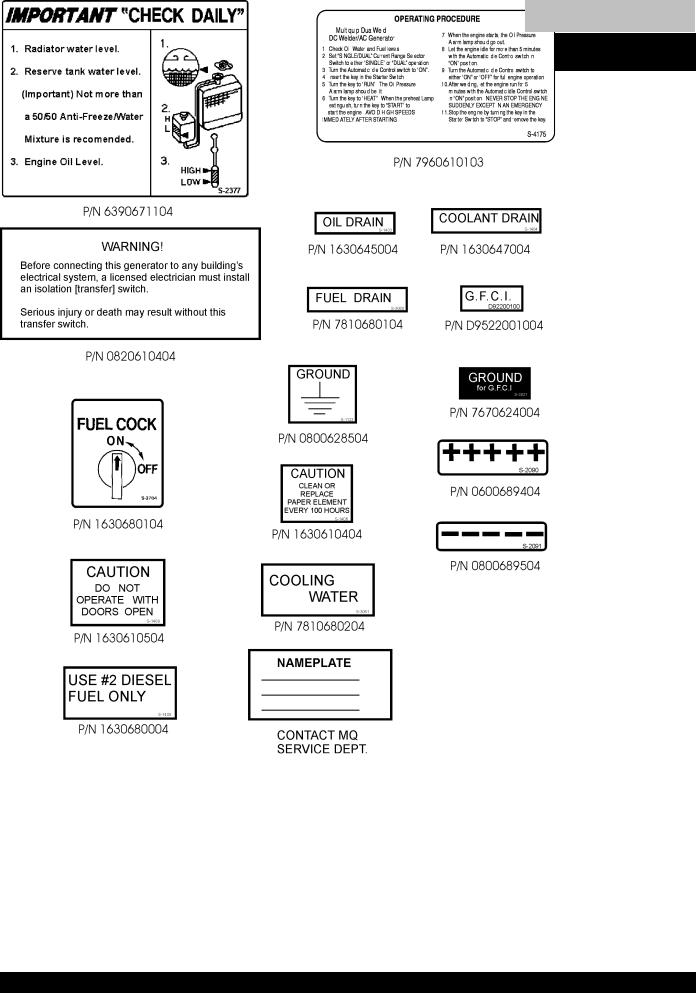
Table of Contents
OPERATION AND SAFETY DECALS
PAGE 8 — BLW-400SSW- WELDER/AC GENERATOR — PARTS & OPERATION MANUAL — REV. #1 (06/15/01)

Table of Contents
OPERATION AND SAFETY DECALS
P/N DCL160
BLW-400SSW-WELDER/AC GENERATOR— PARTS & OPERATION MANUAL— REV. #1 (06/15/01) — PAGE 9

|
|
|
|
|
Table of Contents |
|
|
|
|
|
|
|
|
|
|
BLW-400SSW — SPECIFICATIONS |
||||
|
|
|
|
|
|
|
|
|
|
|
|
|
|
|
|
Table 1. Specifications |
|
|
|
|
|
|
|
|
|
|
|
|
|
Welder Specifications |
|
|
|
|
|
|
|
|
|
|
|
|
Model |
BLW-400SSW |
|
|
|
|
|
|
|
|
|
|
|
|
Type |
Brushless, revolving, field type generator |
|
|||
|
|
|
|
|
|
|
|
Armature Connection |
Single |
|
|
Dual |
|
|
|
|
|
|
|
|
|
Rated Current |
350A |
|
|
175A |
|
|
|
|
|
|
|
|
|
Rated Voltage |
34V |
|
|
27V |
|
|
|
|
|
|
|
|
|
Range of Current |
70~400A |
|
35~200A |
|
|
|
|
|
|
|
|
|
|
|
Generator Specifications |
|
|
|
|
|
|
|
|
|
|
|
|
Frequency |
|
60 Hz |
|
|
|
|
|
|
|
|
|
|
|
Speed |
3600 rpm |
|
|
|
|
|
|
|
|
|
|
|
|
Max. Output |
|
14kW |
|
|
|
|
|
|
|
|
|
|
|
Rated Output |
12.5kW |
|
|
|
|
|
|
|
|
|
|
|
|
Voltage |
120/240 V |
|
|
|
|
|
|
|
|
|
|
|
|
|
Engine Specifications |
|
|
|
|
|
|
|
|
|
|
|
|
Model |
KUBOTA V 1205 |
|
|
|
|
|
|
|
|
|
|
|
|
Type |
4 Cycle, water-cooled, in line, overhead valve |
|
|||
|
|
|
|
|
|
|
|
No. of Cylinders |
4 cylinders |
|
|
|
|
|
|
|
|
|
|
|
|
Bore x Stroke |
2.8 in. x 2.9 in. (72 mm x 73.6 mm) |
|
|||
|
|
|
|
|
|
|
|
Rated Output |
31.5HP/3600 rpm |
|
|
|
|
|
|
|
|
|
|
|
|
Displacement |
73 cu. in. (1198 cc) |
|
|
|
|
|
|
|
|
|
|
|
|
Starting |
Electric |
|
|
|
|
|
|
|
|
|
|
|
|
Coolant Capacity |
1.3 gal. (5 liters) |
|
|
|
|
|
|
|
|
|
|
|
|
Lube Oil Capacity |
1.6 gal. (6 liters) |
|
|
|
|
|
|
|
|
|
|
|
|
Fuel Consumption |
Welding 2 gal. (5L)/hr |
|
|
|
|
|
AC Power 2.1 gal. (7.9L)/hr |
|
||||
|
|
|
||||
|
|
|
|
|
|
|
|
Fuel Capacity |
Approx. 10.6 gal (40 liters) |
|
|||
|
|
|
|
|
|
|
|
Fuel type |
#2 Diesel Fuel |
|
|
|
|
|
|
|
|
|
|
|
|
Battery |
12V70AH |
|
|
|
|
|
|
|
|
|
|
|
The maximum output of the engine listed above is applicable to supplying electrical power for continuous service at ambient conditions in accordance with SAE Test cord J607. The above ambient conditions are at standard sea level, with a barometric reading of 29.92 inches and a temperature of 60 degrees Fahrenheit.
Generally, the engine output power will decrease 3 1/2% for each 1000 feet of altitude above sea level, and 1% for each 10° F Fahrenheit above the standard temperature of 60° F.
PAGE 10 — BLW-400SSW- WELDER/AC GENERATOR — PARTS & OPERATION MANUAL — REV. #1 (06/15/01)
Table of Contents
BLW-400SSW — GENERAL INFORMATION
BLW-400SSW FAMILIARIZATION
Generator
The MQ Power Model BLW-400 welder/AC generator can provide 400 amps of welding current with a single operator or 200 amps of welding current simultaneously with two operators. When used as a welder/AC generator it can provide a maximum of 6,000 watts of power.
Control Panel
The control panel is provided with the following:
!One GFCI 120 volt receptacle, 20 amp
!One 120 volt receptacle, 30 amp
!One 120/240 volt receptacle, 30 amp
!Main Circuit Breaker 265V @25 amps
!Circuit Protector Breaker (GFCI) 120V @20 amps
!Idle Control Switch
!Starter Switch
!Warning Lamp Unit
!Hour Meter
!GroundTerminal
Engine Protection System
Engine protection fail safe features are provided in the event of low oil pressure, high coolant temperature and failure of the battery to charge. If any of the above conditions occur while operating the welder/AC generator, it will cause a complete unit shut down.
Battery Charge Indicator
This unit is equipped with a protective device that signals an indicator and automatically stops the engine when the battery cannot be charged by the alternator.
WaterTemperature Indicator
This unit is equipped with an apparatus that signals an indicator and automatically stops the engine when the cooling water temperature becomes abnormally high. This apparatus will not function properly if the machine is operated with less than the proper amount of coolant.
Oil Pressure Warning Indicator
If low oil pressure is detected while operating the welder/AC generator, the engine protection system will shut down the engine.
If this condition (low oil pressure) should occur, please refer to the engine troubleshooting table (page 44) in this manual.
Excitation System
The BLW-400SSW Welder/AC generator uses a brushless exciter to create rated output electricity. This system will use the mechanical energy generated by the 3600 RPM engine to spin the rotor (or armature) inside the welder/AC generator (or alternator end).
The motion created by the rotor (which holds copper coils) spins inside a housing of permanent magnets called the "STATOR". A magnetic field is created by the stator and produces an electrical current.
Engine
The BLW-400SSW is powered by a 4-cycle KUBOTA diesel engine.This engine is designed to meet every performance requirement for welder/AC generator.ReferenceTable 1, page 10 for engine specifications.
In keeping with MQ Power's policy of constantly improving its products, the specifications quoted herein are subject to change without prior notice.
Idle Control Switch
The BLW-400SSW Welder/AC generator is provided with an automatic idle (engine) control capability for noise suppression and fuel cost reduction. The automatic idle control feature automatically engages under a no-load condition.
When the Idle Control Switch is placed in the “ON” position, the engine revolutions will be approximately 2200 rpm (lowspeed operation). When a load is connected to one of the output receptacles, the engine speed will automatically increase to about 3600 rpm (high-speed operation) within 10 seconds. Conversely, when the load is removed, the engine speed will automatically drop back down to 2200 rpm within
10 seconds.
BLW-400SSW-WELDER/AC GENERATOR— PARTS & OPERATION MANUAL— REV. #1 (06/15/01) — PAGE 11

Table of Contents
BLW-400SSW — DIMENSIONS
Figure 1. BLW-400SSW Dimensions
PAGE 12 — BLW-400SSW- WELDER/AC GENERATOR — PARTS & OPERATION MANUAL — REV. #1 (06/15/01)

Table of Contents
BLW-400SSW — TRAILER-SAFETY GUIDELINES
CAUTION:
ALWAYS make sure the trailer is in good operating condition. Check the tires for proper inflation and wear. Also check the wheel lug nuts for proper tightness.
Explanation of Chart:
This section is intended to provide the user with trailer service and maintenance information. The service and maintenance guidelines referenced in this section apply a wide range of trailers. Remember periodic inspection of the trailer will ensure safe towing of the equipment and will prevent damage to the equipment and personal injury.
It is the purpose of this section to cover the major maintenance components of the trailer. The following trailer components will be discussed in this section:
"Brakes
"Tires
"Lug NutTorquing
"Suspension
"Electrical
"Brake Troubleshooting Tables
Use the following definitions with reading Table 2.
1.Fuel Cell - Provides an adequate amount of fuel for the equipment in use. Fuel cells must be empty when transporting equipment.
2.Braking System - System employed in stopping the trailer. Typical braking systems are electric, surge, hydraulic, hydraulic-surge and air.
3.GVWR- Gross Vehicle Weight Rating (GVWR), is the maximum number of pounds the trailer can carry, including the fuel cell (empty).
4.Frame Length - This measurement is from the ball hitch to the rear bumper (reflector).
5.Frame Width - This measurement is from fender to fender.
6.Jack Stand - Trailer support device with maximum pound requirement from the tongue of the trailer.
7.Coupler - Type of hitch used on the trailer for towing.
8.Tire Size - Indicates the diameter of the tire in inches (10,12,14, etc.), and the width in millimeters (175,185,205, etc.). The tire diameter must match the diameter of the tire rim.
9.Tire Ply - The tire ply (layers) number is rated in letters; 2-ply,4-ply,6-ply, etc.
10.Wheel Hub - The wheel hub is connected to the trailer’s axle.
11.Tire Rim - Tires mounted on a tire rim. The tire rim must match the size of the tire.
12.Lug Nuts - Used to secure the wheel to the wheel hub. Always use a torque wrench to tighten down the lug nuts. See Table 4 and Figure 5 or lug nut tightening and sequence.
13.Axle - Indicates the maximum weight the axle can support in pounds, and the diameter of the axle expressed in inches (see Table 3). Please not that some trailers have a double axle. This will be shown as 2-6000 lbs., meaning two axles with a total weight capacity of 6000 pounds.
14.Suspension - Protects the trailer chassis from shocks transmitted through the wheels. Types of suspension used are leaf, Q-flex, and air ride.
15.Electrical - Electrical connectors (looms) are provided with the trailer so the brake lights and turn signals can be connected to the towing vehicle.
16.Application - Indicates which units can be employed on a particular trailer.
BLW-400SSW-WELDER/AC GENERATOR— PARTS & OPERATION MANUAL— REV. #1 (06/15/01) — PAGE 13

Table of Contents
BLW-400SSW — TRAILER-SPECIFICATIONS
Table 2. Specifications
MODEL |
APPLICATION |
FUEL |
BRAKE |
GVWR |
FRAME |
FRAME |
JACK |
|
|
CELL |
SYSTEM |
|
LENGTH |
WIDTH |
STAND |
|
|
|
|
|
|
|
|
TRLR-10-15 |
TLG-12, DCA15, |
NO |
NO |
1900LBS |
96" |
50" |
800LB. |
|
TLW-300 |
|
|
|
|
|
FULL TILT WHEEL |
|
|
|
|
|
|
|
|
TRLR-10X |
TLG-12, DCA15, |
NO |
NO |
1900LBS |
96" |
50" |
800LB. |
|
TLW-300 |
|
|
|
|
|
FULL TILT WHEEL |
|
|
|
|
|
|
|
|
TRLR-10XF |
TLG-12, DCA15, |
51 GAL |
NO |
1900LBS |
96" |
50" |
800LB. |
|
TLW-300 |
|
|
|
|
|
FULL TILT WHEEL |
|
|
|
|
|
|
|
|
TRLR-225W |
DCA-10 |
NO |
NO |
2200LBS |
85" |
42" |
800LB. |
|
|
|
|
|
|
|
FULL TILT WHEEL |
|
|
|
|
|
|
|
|
BLW-400 |
BLW-400 |
NO |
ELECTRIC |
2700LBS |
W/MAST 154" |
55" |
800LB. |
|
|
|
|
|
W/O 124" |
(78" TALL) |
FULL TILT WHEEL |
|
|
|
|
|
|
|
|
TRLR-15XF |
DCA-15 |
41 GAL |
NO |
2700LBS |
124" |
55" |
800LB. |
|
|
|
|
|
|
|
FULL TILT WHEEL |
|
|
|
|
|
|
|
|
TRLR-50X |
DCA-25 |
NO |
NO |
2700LBS |
124" |
55" |
800LB. |
|
|
|
|
|
|
|
FULL TILT WHEEL |
|
|
|
|
|
|
|
|
TRLR-50XF |
DCA-25 |
41 GAL |
NO |
2700LBS |
124" |
55" |
800LB. |
|
|
|
|
|
|
|
FULL TILT WHEEL |
|
|
|
|
|
|
|
|
TRLR-25SBT |
DCA-25 |
NO |
NO |
2990LBS |
120" |
66" |
800LB. |
|
|
|
|
|
|
|
FULL TILT WHEEL |
|
|
|
|
|
|
|
|
TRLR-70W |
DCA-45, -60, 70 |
NO |
SURGE |
7000LBS |
186" |
77" |
2000LB. |
|
|
|
|
|
|
|
FLAT PAD |
|
|
|
|
|
|
|
|
TRLR-70X |
DCA-45, -60, 70 |
OPT |
SURGE |
7000LBS |
138" |
66" |
2000LB. |
|
|
|
|
|
|
|
FLAT PAD |
|
|
|
|
|
|
|
|
TRLR-70XF |
DCA-45, -60, 70 |
53 GAL |
SURGE |
7000LBS |
138" |
66" |
2000LB. |
|
|
|
|
|
|
|
FLAT PAD |
|
|
|
|
|
|
|
|
TRLR-100XF |
DCA-100, 125 |
150 GAL |
HYDRAULIC SURGE |
7000LBS |
190" |
76" |
2000LB. |
|
|
|
|
|
|
|
FLAT PAD |
|
|
|
|
|
|
|
|
TRLR-85/125 |
DCA-85, 100, |
145 GAL |
HYDRAULIC |
10000LBS |
186" |
77" |
2000LB. |
|
125 |
|
|
|
|
|
FLAT PAD |
|
|
|
|
|
|
|
|
TRLR-150XF |
DCA-150, 180 |
200 GAL |
HYDRAULIC SURGE |
11160LBS |
204" |
84" |
5000 LB. |
|
|
|
|
|
|
|
FLAT PAD |
|
|
|
|
|
|
|
|
TRLR-220XF |
DCA-220 |
250 GAL |
HYDRAULIC SURGE |
14000LBS |
222" |
83" |
5000 LB. |
|
|
|
|
|
|
|
FLAT PAD |
|
|
|
|
|
|
|
|
TRLR-300XF |
DCA-300 |
250 GAL |
HYDRAULIC SURGE |
18000LBS |
238" |
83" |
5000 LB. |
|
|
|
|
|
|
|
FLAT PAD |
|
|
|
|
|
|
|
|
TRLR-400XF |
DCA-400 |
350 GAL |
ELECTRIC |
18000LBS |
238" |
83" |
5000 LB. |
|
|
|
|
|
|
|
FLAT PAD |
|
|
|
|
|
|
|
|
TRLR-600XF |
DCA-600, 800 |
550 GAL |
AIR |
30000LBS |
384" |
96" |
5000 LB. |
|
|
|
|
|
|
|
FLAT PAD |
|
|
|
|
|
|
|
|
TRLR-800SX |
DCA-600, 800 |
550 GAL |
AIR |
30000LBS |
384" |
96" |
5000 LB. |
|
|
|
|
|
|
|
FLAT PAD |
|
|
|
|
|
|
|
|
PAGE 14 — BLW-400SSW- WELDER/AC GENERATOR — PARTS & OPERATION MANUAL — REV. #1 (06/15/01)

Table of Contents
BLW-400SSW — TRAILER-SPECIFICATIONS
Table 2. Specifications (Con't)
MODEL |
COUPLER |
TIRES |
WHEELS |
AXLE |
HUBS |
SUSPENSION |
ELECTRICAL |
|
|
|
|
|
|
|
|
TRLR-10-15W |
2" BALL CLASS |
175-13C |
13"X4.50" |
2200# 2X2 |
5 LUG |
3 LEAF |
4 WIRE LOOM W/ |
|
2 ADJUSTABLE |
|
|
|
|
|
4 POLE FLAT |
|
|
|
|
|
|
|
|
TRLR-10X |
2"BALL CLASS |
175-13C |
13"X4.5" |
2200#2X2 |
5 LUG |
3 LEAF |
4 POLE FLAT |
|
2 ADJUSTABLE |
|
|
|
|
|
|
|
|
|
|
|
|
|
|
TRLR-10XF |
2"BALL CLASS |
175-13C |
13"X4.5" |
2200#2X2 |
5 LUG |
3 LEAF |
4 POLE FLAT |
|
2 ADJUSTABLE |
|
|
|
|
|
|
|
|
|
|
|
|
|
|
TRLR-225W |
2"BALL CLASS |
175-13B |
13X4.5" |
2200#2X2 |
5 LUG |
Q FLEX |
4 POLE FLAT |
|
2 ADJUSTABLE |
|
|
|
|
|
|
|
|
|
|
|
|
|
|
BLW 400 |
2"BALL CLASS |
175-13C |
13 X 4.5" |
2200#2X2 |
5 LUG |
3 LEAF |
4 POLE FLAT |
|
2 ADJUSTABLE |
|
|
|
|
|
|
|
|
|
|
|
|
|
|
TRLR-15XF |
2" BALL CLASS |
B78-13LRC |
13"X4.50" |
3500# 2-1/2" |
5 LUG |
4 LEAF |
4 POLE RUBBER |
|
|
|
|
|
|
|
FLAT |
|
|
|
|
|
|
|
|
TRLR-50X |
2" BALL CLASS |
B78-13LRC |
13"X4.50" |
3500lbs. |
5 LUG |
4 LEAF |
4 POLE RUBBER |
|
|
|
|
2-3/8" |
|
|
FLAT |
|
|
|
|
|
|
|
|
TRLR-50XF |
2" BALL CLASS |
B78-13LRC |
13"X4.50" |
3500lbs. |
5 LUG |
4 LEAF |
4 POLE RUBBER |
|
|
|
|
2-3/8" |
|
|
FLAT |
|
|
|
|
|
|
|
|
TRLR-70W |
2" BALL CLASS |
205-14C |
14"X5" |
3500lbs. |
5 LUG |
5 LEAF |
4 POLE RUBBER |
|
3" ADJUSTABLE |
BIAS (4) |
|
3" |
|
|
FLAT |
|
|
|
|
|
|
|
|
TRLR-70X |
2" BALL CLASS |
205-14C |
14"X5" |
3500lbs |
5 LUG |
5 LEAF |
4 POLE RUBBER |
|
3" ADJUSTABLE |
BIAS (4) |
|
3" |
|
|
FLAT |
|
|
|
|
|
|
|
|
TRLR-70XF |
2" BALL CLASS |
205-14C |
14"X5" |
3500lbs. |
5 LUG |
5 LEAF |
4 POLE RUBBER |
|
3" ADJUSTABLE |
BIAS (4) |
|
3" |
|
|
FLAT |
|
|
|
|
|
|
|
|
TRLR-100XF |
ADJUSTABLE 2-5/6 |
205-15C |
14"X5.5" |
3500lbs |
5 LUG |
5 LEAF |
4 WIRE LOOM |
|
OPT 3" EYE |
BIAS (4) |
|
3" |
|
|
|
|
|
|
|
|
|
|
|
TRLR-85/125 |
ADJUSTABLE 2-5/6 |
ST225/75R15D |
14"x6" |
(2)-6000lbs |
6 LUG |
7 LEAF |
4 WIRE LOOM |
|
OPT 3" EYE |
RADIAL (4) |
|
|
|
|
|
|
|
|
|
|
|
|
|
TRLR-150XF |
3" BALL EYE |
750-16 E |
16"X7" |
(2)-6000lbs |
8 LUG |
7 LEAF |
4 WIRE LOOM |
|
|
BIAS (4) |
|
|
|
|
|
|
|
|
|
|
|
|
|
TRLR-220XF |
3" EYE |
ST235/85R16E |
16"X7" |
(2)-7000lbs |
8 LUG |
Q FLEX |
4 WIRE LOOM |
|
ADJUSTABLE |
RADIAL(4) |
|
|
|
|
|
|
|
|
|
|
|
|
|
TRLR-300XF |
3" EYE |
ST235/85R16E |
16"X7" |
(2)-6000lbs |
8 LUG |
Q FLEX |
4 WIRE LOOM |
|
ADJUSTABLE |
RADIAL(6) |
|
|
|
|
|
|
|
|
|
|
|
|
|
TRLR-400XF |
3" EYE |
ST235/85R16E |
16"X7" |
(3)-7000lbs. |
8 LUG |
Q FLEX |
4 WIRE LOOM |
|
ADJUSTABLE |
RADIAL(6) |
|
|
|
|
|
|
|
|
|
|
|
|
|
TRLR-600XF |
5TH WHEEL |
ST215/75R17.5H |
16"X7" |
(3)-10000lbs |
8 LUG |
7 LEAF |
6 WIRE LOOM |
|
|
RADIAL (8) |
|
|
|
|
|
|
|
|
|
|
|
|
|
TRLR-800AR |
5TH WHEEL |
ST215/75R17.5H |
16"X7" |
(3)-10000lbs |
8 LUG |
AIR-RIDE |
6 WIRE LOOM |
|
|
RADIAL (8) |
|
|
|
|
|
|
|
|
|
|
|
|
|
BLW-400SSW-WELDER/AC GENERATOR— PARTS & OPERATION MANUAL— REV. #1 (06/15/01) — PAGE 15

Table of Contents
BLW-400SSW —TRAILER SAFETY GUIDELINES
Brakes
If your trailer has a braking system, the brakes should be inspected the first 200 miles of operation. This will allow the brake shoes and drums to seat properly. After the first 200 mile interval, inspect the brakes every 3,000 miles. If driving over rough terrain, inspect the brakes more frequently.
Electric Brakes
Electrically actuated brakes (Figure 2) are similar to hydraulic brakes. The basic difference is that hydraulic brakes are actuated by an electromagnet.
Listed below are some of the advantages that electric brakes have over hydraulic brakes:
"Brake system can be manually adjusted to provide the corrected braking capability for varying road and load conditions
"Brake system can be modulated to provide more or less braking force, thus easing the brake load on the towing vehicle
"Brake system has very little lag time between the time the vehicle’s brakes are actuated and the trailer’s brakes are actuated
"Brake system can provide an independent emergency brake system
Remember in order to properly synchronize the tow vehicle’s braking to the trailer’s braking, can only be accomplished by road testing. Brake lockup, grabbiness or harshness is due to lack of synchronization between the tow vehicle and the trailer being towed or under-adjusted brakes.
Before any brake synchronizations adjustments can be made, the trailer brakes should be burnished-in by applying the brakes 20-30 times with approximately a 20 m.p.h. decrease in speed, e.g. 40 m.p.h. to 20 m.p.h. Allow ample time for brakes to cool between application. This allows the brake shoes to slightly be seated into the brake drum surface.
Figure 2 displays the major electric brake components that will require inspection and maintenance. Please inspect these components as required.
Electric Brake Adjustment
1.Place the trailer on jack stands. Make sure the jack stands are placed on secure level ground.
2.Check the wheel and drum for free rotation.
3.Remove the adjusting hole cover from the adjusting slot at the bottom brake backing plate.
4.With a screwdriver or standard adjusting tool, rotate the star wheel of the adjuster assembly to expand the brake shoes.
5.Adjust the brake shoes outward until the pressure of the lining against the wheel drum makes the wheel difficult to turn.
6.Rotate the star wheel in the opposite direction until the wheel rotates freely with slight lining drag.
7.Replace the adjusting hole cover and lower the trailer to the ground.
8.Repeat steps 1 through 6 on the remaining brakes.
Figure 2. Electrical Brake Components
PAGE 16 — BLW-400SSW- WELDER/AC GENERATOR — PARTS & OPERATION MANUAL — REV. #1 (06/15/01)
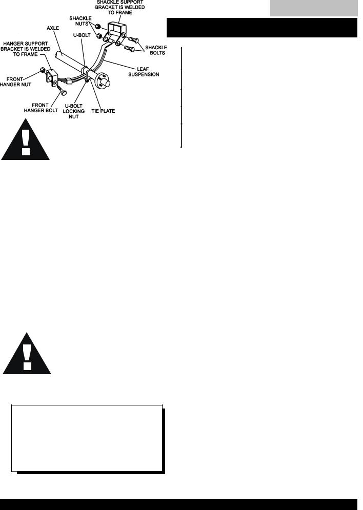
Table of Contents
BLW-400SSW —TRAILER SAFETY GUIDELINES
Tires/Wheels/Lug Nuts
Tires and wheels are a very important and critical components of the trailer. When specifying or replacing the trailer wheels it is important the wheels, tires, and axle are properly matched.
CAUTION:
DO NOT attempt to repair or modify a wheel. DO NOT install in inner tube to correct a leak through the rim. If the rim is cracked,
the air pressure in the inner tube may cause pieces
of the rim to explode (break off) with great force and cause serious eye or bodily injury.
Tire Wear/Inflation
Tire inflation pressure is the most important factor in tire life. Pressure should be checked cold before operation DO NOT bleed air from tires when they are hot. Check inflation pressure weekly during use to insure the maximum tire life and tread wear.
Table 3 (Tire Wear Troubleshooting) will help pinpoint the causes and solutions of tire wear problems.
CAUTION:
Suspension
The leaf suspension springs and associated components (Figure 3) should be visually inspected every 6,000 miles for signs of excessive wear, elongation of bolt holes, and loosening of fasteners. Replace all damaged parts (suspension) immediately. Torqued suspension components as detailed in Table 4.
NOTE |
Figure 3. Major Suspension Components |
|
ALWAYS wear safety glasses when removing or installing force fitted parts. Failure to comply may result in serious injury.
BLW-400SSW-WELDER/AC GENERATOR— PARTS & OPERATION MANUAL— REV. #1 (06/15/01) — PAGE 17

Table of Contents
BLW-400SSW —TRAILER SAFETY GUIDELINES
Table 4. Suspension Torque Requirements
Item |
Torque (Ft.-Lbs.) |
|
|
3/8" U-BOLT |
MIN-30 MAX-35 |
|
|
7/16" U-BOLT |
MIN-45 MAX-60 |
|
|
1/2" U-BOLT |
MIN-45 MAX-60 |
|
|
SHACKLE BOLT |
SNUG FIT ONLY. PARTS MUST ROTATE FREELY. |
SPRING EYE BOLT |
LOCKING NUTS OR COTTER PINS ARE PROVIDED TO |
|
RETAIN NUT-BOLT ASSEMBLY. |
|
|
SHOULDER TYPE |
MIN-30 MAX-50 |
SHACKLE BOLT |
|
|
|
Lug Nut Torque Requirements
It is extremely important to apply and maintain proper wheel mounting torque on the trailer. Be sure to use only the fasteners matched to the cone angle of the wheel. Proper procedure for attachment of the wheels is as follows:
1.Start all wheel lug nuts by hand.
2.Torque all lug nuts in sequence. See Figure 4. DO NOT torque the wheel lug nuts all the way down. Tighten each lug nut in 3 separate passes as defined by Table 5.
3.After first road use, retorque all lug nuts in sequence. Check all wheel lug nuts periodically.
Table 5. Tire Torque Requirements
Wheel Size |
First Pass |
Second Pass |
Third Pass |
|
FT-LBS |
FT-LBS |
FT-LBS |
|
|
|
|
12" |
20-25 |
35-40 |
50-65 |
|
|
|
|
13" |
20-25 |
35-40 |
50-65 |
|
|
|
|
14" |
20-25 |
50-60 |
90-120 |
|
|
|
|
15" |
20-25 |
50-60 |
90-120 |
|
|
|
|
16" |
20-25 |
50-60 |
90-120 |
|
|
|
|
Figure 4. Wheel Lug Nuts Tightening Sequence
NOTE
NEVER use an pneumatic air gun to tighten wheel lug nuts.
PAGE 18 — BLW-400SSW- WELDER/AC GENERATOR — PARTS & OPERATION MANUAL — REV. #1 (06/15/01)
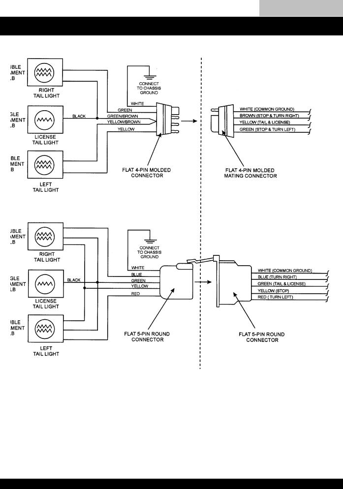
Table of Contents
BLW-400SSW —TRAILER-WIRING DIAGRAM
BLW-400SSW-WELDER/AC GENERATOR— PARTS & OPERATION MANUAL— REV. #1 (06/15/01) — PAGE 19

Table of Contents
BLW-400SSW —TRAILER-BRAKETROUBLESHOOTING
Table 6. Electric Brake Troubleshooting
Symptom |
Possible Cause |
Solution |
|
|
|
|
|
No Brakes or Intermittent Brakes |
Any open circuits or broken wires? |
Find and correct. |
|
|
|
|
|
|
Any short circuits? |
Find and correct. |
|
|
|
|
|
|
Faulty controller? |
Test and correct. |
|
|
|
|
|
|
Any loose connections? |
Find and repair. |
|
|
|
|
|
|
Ground wire secure? |
Find and secure. |
|
|
|
|
|
Weak Brakes or Brakes Pull to |
Grease or oil on magnets or linings? |
Clean or replace. |
|
One Side |
|
|
|
Connections corroded? |
Clean and correct cause |
||
|
|||
|
|
of corrosion. |
|
|
|
|
|
|
Brake drums scored or grooved? |
Machine or replace. |
|
|
|
|
|
|
Brakes synchronized? |
Correct. |
|
|
|
|
|
Locking Brakes |
Brake components loose, bent or broken? |
Replace components. |
|
|
|
|
|
|
Brake drums out-of-round? |
Replace. |
|
|
|
|
|
Noisy Brakes |
System lubricated? |
Lubricate. |
|
|
|
|
|
|
Brake components correct? |
Replace and correct. |
|
|
|
|
|
Dragging Brakes |
Bearings of the wheel adjusted? |
Adjust. |
|
|
|
|
PAGE 20 — BLW-400SSW- WELDER/AC GENERATOR — PARTS & OPERATION MANUAL — REV. #1 (06/15/01)
Towing Safety Precautions
CAUTION :
Check with your county or state safety towing regulations department before towing your generator. Vehicle towing codes and regulations can vary from state to state.
To reduce the possibility of an accident while transporting the generator on public roads, always make sure the trailer (Figure 5) and the towing vehicle are in good operating condition and both units are mechanically sound.
The following list of suggestions should be used when towing your generator:
■Make sure the hitch and coupling of the towing vehicle are rated equal to, or greater than the trailer "gross vehicle weight rating" (GVWR).
■ALWAYS inspect the hitch and coupling for wear. NEVER tow a trailer with defective hitches, couplings, chains etc.
■Check the tire air pressure on both the towing vehicle and the trailer.Also check the tire tread wear on both vehicles.
■ALWAYS make sure the trailer is equipped with a "Safety Chain".
Table of Contents
BLW-400SSW —TOWING
■ALWAYS attach trailer's safety chain to bumper of towing vehicle.
■ALWAYS make sure the vehicle and trailer directional, backup, brake, and trailer lights are connected and are working properly.
■The maximum speed (unless otherwise posted) for highway towing is 45 MPH. Recommended off-road towing is not to exceed 10 MPH or less, depending on type of terrain.
■Place chocked blocks underneath wheel to prevent rolling, while parked.
■Place support blocks underneath the trailer's bumper to prevent tipping, while parked.
■Use the trailer's hand winch to adjust the height of the trailer, then insert locking pin to lock wheel stand in place, while parked.
■Avoid sudden stops and starts.This can cause skidding, or jackknifing. Smooth, gradual starts and stops will improve gas milage.
■Avoid sharp turns to prevent rolling.
■Remove wheel stand when transporting.
■DO NOT transport generator with fuel in tank.
Figure 5. Welder/AC Generator and Towing Trailer
BLW-400SSW-WELDER/AC GENERATOR— PARTS & OPERATION MANUAL— REV. #1 (06/15/01) — PAGE 21

Table of Contents
BLW-400SSW — CONTROLS AND INDICATORS
Figure 6. Controls and Indicators
PAGE 22 — BLW-400SSW- WELDER/AC GENERATOR — PARTS & OPERATION MANUAL — REV. #1 (06/15/01)

Table of Contents
BLW-400SSW — CONTROLS AND INDICATORS
Figure 6 shows the location of the controls and indicators.The functions of each control or indicator is described below.
1.DC Current Selector/Single-Use to select current when using welder for single operator.
2.Current Range Selector- Use to select for single or dual welding operators.
3.DC Current Selector/Dual- Use to select current when using welder for dual operators.
4.AC Voltmeter-Indicates the output of total voltage with welder and/or generator.
5.AC Circuit Breaker- This 53 amp main circuit breaker will shut down current if welder/generator is overloaded.
6.Engine Indicator Lamps- Lights red when the following conditions occur:
!Low Oil Pressure
!High Water Temperature
!Electrical System Is Not Charging Properly
7.Preheat Indicator-Indicates the engine is warmed up for welding/adding load.
8.Ignition Switch – With key inserted turn clockwise to start engine.
9.Hour Meter – Indicates number of hours machine has been in use or hours engine was run.
10.Idle Switch- Turn on for rpms to automatically adjust rpms when a load is added.
11.Fuel Gauge – Indicates the amount of fuel in the fuel tank.
BLW-400SSW-WELDER/AC GENERATOR— PARTS & OPERATION MANUAL— REV. #1 (06/15/01) — PAGE 23
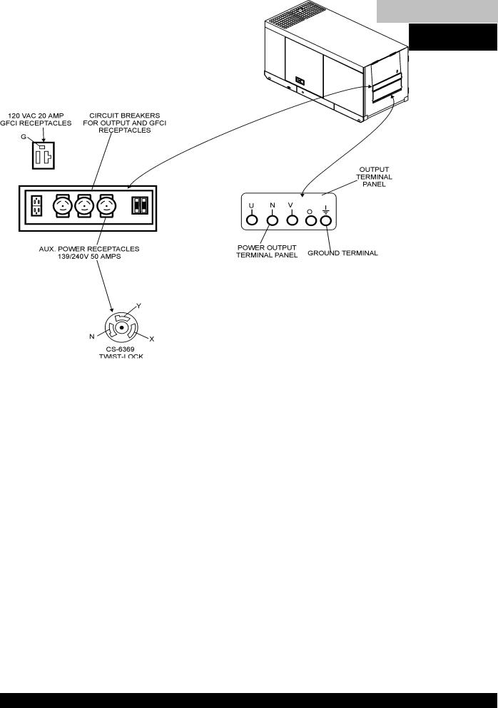
Table of Contents
BLW-400SSW — OUTPUT TERMINAL OVERVIEW
|
120 Volt Receptacle |
|
One GFCI Duplex Nema 5-20R (120V, 20 Amp) receptacle |
|
is provided on the output terminal. This receptacle can be |
|
used anytime the generator is in operation. The receptacle |
|
is controlled by the circuit breaker located on the control |
|
panel. |
|
The reset button is for the GFCI when the circuit is tripped. |
|
Pressing the "Test Button" (See Figure 9) in the center of |
|
this receptacle will check the GFCI function. The receptacle |
Figure 8. Duplex Receptacle Detail |
should be tested at least once a month. |
Figure 9. GFCI Test Button
PAGE 24 — BLW-400SSW- WELDER/AC GENERATOR — PARTS & OPERATION MANUAL — REV. #1 (06/15/01)

Table of Contents
BLW-400SSW — OUTPUT TERMINAL OVERVIEW
Output Terminal Panel Available Voltages
The BLW-400SSW is a single phase generator only. It is able to supply both 120 volt and 240 volt.
120V Hard Wire Hookup
The output terminal panel, when suppling single phase 120 volts, will provide two circuits available at 41.7 amps with any two wires plus the ground. (See Figure 10 below.)
Maximum Amps
The BLW-400SSW can provide 41.7 amps at 120 or 240 volts. Do not exceed the maximum amps!
240V Hard Wire Hookup
The output terminal panel, when suppling single phase 240 volts, will provide one circuit available at 41.7 amps with two wires plus the ground. (See Figure 11 below.)
Figure 10. Hard Wire Hookup for |
Figure 11. Hard Wire Hookup for |
120 Volt |
240 Volt |
NOTE
When using plural single phase voltages, make sure to balance the load on each of the single phase legs.
BLW-400SSW-WELDER/AC GENERATOR— PARTS & OPERATION MANUAL— REV. #1 (06/15/01) — PAGE 25

Table of Contents
BLW-400SSW — INSTALLATION
Outdoor Installation
Install the welder/AC generator in a location where it will not be exposed to rain or sunshine. Make sure the Welder/AC generator is on secure level ground so it cannot slide or shift around. Also install the welder/AC generator so the exhaust will not be discharged in the direction of nearby homes.
The installation site must be relatively free from moisture and dust. All electrical equipment should be protected from excessive moisture. Failure to do will result in deterioration of the insulation, and will result in short circuits.
Foreign materials such as dust, sand, lint and abrasive materials will cause excessive wear to engine and alternator parts.
CAUTION :
Pay close attention to ventilation when operating the welder/AC generator inside tunnels and caves. The engine exhaust contains noxious elements.
Indoor Installation
Exhaust gases from diesel engines are extremely poisonous.
Whenever an engine is installed indoors the exhaust fumes must be vented to the outside.The engine should be installed at least two feet from any outside wall. Using an exhaust pipe which is too long or too small can cause excessive back pressure and cause the engine to heat excessively.
Eliminate the danger of deadly carbon monoxide gas. Remember that exhaust fumes from any diesel engine are very poisonous if discharged in a closed room, but harmless if allowed to mix with the outside air. If the welder/AC generator is installed indoors, you must make provisions for venting the engine exhaust to the outside of the building.
CAUTION :
An electric shock may happen when vibrators are used. Pay close attention to handling when operating vibrators and always use rubber boots and gloves to insulate the body from a electrical shock.
PAGE 26 — BLW-400SSW- WELDER/AC GENERATOR — PARTS & OPERATION MANUAL — REV. #1 (06/15/01)

Table of Contents
BLW-400SSW — PRE-SETUP
General Inspection Prior to Operation
The BLW-400SSW utilizes a welder/AC generator that has been thoroughly inspected and accepted prior to shipment from the factory. However, be sure to check for damaged parts or components, or loose nuts and bolts, which could have occurred in transit.
Ground
The nut and ground terminal on the welder/AC generator should always be used to connect to a suitable ground.The ground path should be of #8 size wire.
Connect the terminal of the ground wire between the lock washer and the nut and tighten the nut fully. Connect their end of the wire to a suitable ground.
Circuit Breakers
To protect the welder/AC generator from an overload, a 3-pole, 53 amp, main circuit breaker is provided. In addition 2-two pole, 25 amp breaker is provided for the G.F.C.I.receptacles. Make sure to switch both circuit breakers to the "OFF" position prior to starting the engine.
Extension Cable
When electric power is to be provided to various tools or loads at some distance from the welder/AC generator, extension cords are normally used. Cables should be sized to allow for distance in length and amperage so that the voltage drop between the welder/AC generator and point of use (load) is held to a minimum.Use the cable selection chart (Table 7 ) as a guide for selecting proper cable size.
Table 7. Cable Selection (60 Hz, Single Phase Operation)
Current in |
Load In Watts |
|
|
Maximum Allowable Cable Length |
|
|||||
|
|
|
|
|
|
|
|
|
|
|
At 120 |
At 240 |
|
|
|
|
|
|
|
|
|
Amperes |
#10 Wire |
|
#12 Wire |
#14 Wire |
|
#16 Wire |
||||
|
Volts |
Volts |
|
|
||||||
|
|
|
|
|
|
|
|
|
||
|
|
|
|
|
|
|
|
|
|
|
2.5 |
300 |
600 |
1000 ft. |
|
600 |
ft. |
375 ft. |
|
250 ft. |
|
|
|
|
|
|
|
|
|
|
|
|
5 |
600 |
1200 |
500 |
ft. |
|
300 |
ft. |
200 ft. |
|
125 ft. |
|
|
|
|
|
|
|
|
|
|
|
7.5 |
900 |
1800 |
350 |
ft. |
|
200 |
ft. |
125 ft. |
|
100 ft. |
|
|
|
|
|
|
|
|
|
|
|
10 |
1200 |
2400 |
250 |
ft. |
|
150 ft. |
100 ft. |
|
|
|
|
|
|
|
|
|
|
|
|
||
15 |
1800 |
3600 |
150 ft. |
|
100 ft. |
65 ft. |
|
|
||
|
|
|
|
|
|
|
|
|
||
20 |
2400 |
4800 |
125 ft. |
|
75 ft. |
50 ft. |
|
|
||
|
|
|
|
|
|
|
|
|
||
CAUTION: Equipment damage can result from low voltage. |
|
|
|
|
||||||
|
|
|
|
|
|
|
|
|
|
|
BLW-400SSW-WELDER/AC GENERATOR— PARTS & OPERATION MANUAL— REV. #1 (06/15/01) — PAGE 27
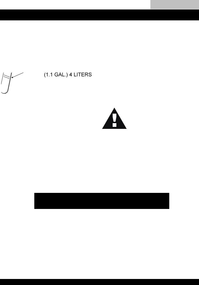
Table of Contents
BLW-400SSW — PRE-SETUP
Lubrication Oil |
Fuel |
Fill the engine crankcase with lubricating oil through the filler hole, but do not overfill. Make sure the welder/AC generator is level. With the dipstick inserted all the way, but without being screw into the filler hole, verify that the oil level is maintained between the two notches (Figure 12) on the dipstick. See Table 8 for proper selection of engine oil.
Fill the fuel tank with clean diesel fuel. Do not fill the tank beyond capacity.
Pay attention to the fuel tank capacity when replenishing fuel. Refer to the fuel tank capacity listed on page 10 Specification Table 1.
The fuel tank cap must be closed tightly after filling. Handle fuel in a safety container. If the container does not have a spout, use a funnel.
CAUTION :
|
Never fill the fuel tank while the engine is |
|
running or in the dark. Fuel spillage on a |
|
hot engine can cause a fire or explosion. |
|
If fuel spillage occurs, wipe up the spilled |
|
gasoline completely to prevent fire |
|
hazards. |
|
Coolant |
|
Use only drinkable tap water. If hard water or water with |
|
many impurities is used, the inside of the engine and radiator |
Figure 12. Engine Oil Dipstick |
may become coated with deposits and cooling efficiency |
will be reduced. |
|
|
An anticorrosion additive added to the water will help prevent |
|
deposits and corrosion in the cooling system. See the |
|
Kobota Engine Operator's Manualfor further details. |
Table 8. Recommended Motor Oil
Temperature Range |
Type Oil |
|
|
|
|
104° F ~ 23° F |
SAE 30 |
|
(40° C ~ -5°C) |
||
|
||
|
|
|
23° F ~ 5° F |
SAE 20 or SAE 10W-30 |
|
(-5° C ~ -15°C) |
||
|
||
|
|
|
Below 5° C (-15°) |
SAE 10W or SAE 10W-30 |
|
|
|
PAGE 28 — BLW-400SSW- WELDER/AC GENERATOR — PARTS & OPERATION MANUAL — REV. #1 (06/15/01)
Table of Contents
BLW-400SSW — PRE-SETUP
CAUTION :
When adding coolant or antifreeze to the radiator, do not remove the radiator cap until the unit has completely cooled.
Day-to-day addition of coolant or antifreeze is done from the reserve tank. See Table 9 for engine, radiator and reserve tank coolant capacities. Make sure the coolant level in the reserve tank is always between the "H" and the "L" markings.
Table 9. Coolant Capacity
Engine and Radiator |
1.1 Gal. (4.16L) |
|
|
Reserve Tank |
0.2 Gal. (0.75L) |
|
|
Cleaning the Radiator
The radiator may overheat if the fins become overloaded with dust or debris. Periodically clean the radiator fins with compressed air.
Fan Belt Tension
A slack fan belt may contribute to overheating, or to insufficient charging of the battery. Inspect and adjust it in accordance with the Kubota Engine Operator's Manual.
The fan belt tension is proper if the fan belt (Figure 5) bends 7 to 9 mm (0.28to 0.35 in.) when depressed with the thumb as shown in Figure 13 below.
Operation in Freezing Weather
When operating in freezing weather, be certain that the proper amount of antifreeze has been added. See Table 10 for antifreeze operating temperatures.
Table 10. Anti-Freeze Operating Temperatures
Vol % |
Freezing Point |
Boiling Point |
||
|
|
|
|
|
Anti-Freeze |
°C |
°F |
°C |
°F |
|
||||
|
|
|
|
|
40 |
-24 |
-12 |
106 |
222 |
|
|
|
|
|
50 |
-37 |
-34 |
108 |
226 |
|
|
|
|
|
NOTE
When the antifreeze is mixed with water, the antifreeze mixing ratio must be less than 50%.
Figure 13. Fan Belt Tension
CAUTION :
Never place hands near the belts or fan while the welder/AC generator is running.
Air Cleaner
Periodic cleaning/replacement is necessary. Inspect it in accordance with the Kobota Engine Operator's Manual.
Battery
This unit is of negative ground. DO NOT connect in reverse. Always maintain battery fluid level between the specified marks. Battery life will be shortened, if the fluid level is not properly maintained. Add only distilled water when replenishment is necessary.
The battery is sufficiently charged if the specific gravity of the battery fluid is 1.28 (at 68° F). If the specific gravity should fall to 1.245 or lower, it indicates that the battery is dead and needs to be recharged or replaced.
Check to see whether the battery cables are loose. Poor contact may result in poor starting or malfunctions, always keep the terminals firmly tightened. Coating the terminals with a thin film of grease will help to inhibit corrosion.
BLW-400SSW-WELDER/AC GENERATOR— PARTS & OPERATION MANUAL— REV. #1 (06/15/01) — PAGE 29
Table of Contents
BLW-400SSW — LOAD APPLICATION
Single Phase Load
Always be sure to check the nameplate on the welder/AC generator and equipment to insure the wattage, amperage and frequency requirements are satisfactorily supplied by the welder/AC generator for operating the equipment.
CAUTION:
Motors and motor-driven equipment draw much greater current for starting than during operation.
Generally, the wattage listed on the nameplate of the equipment is its rated output. Equipment may require 130—
150% more wattage than the rating on the nameplate, as the wattage is influenced by the efficiency, power factor and starting system of the equipment.
NOTE
If wattage is not given on the equipment's name plate, approximate wattage may be determined by multiplying nameplate voltage by the nameplate amperage.
WATTS = VOLTAGE x AMPERAGE
The power factor of this welder/AC generator is 1.0. See
Table 11 below when connecting loads.
Table 11. Power Factor By Load
Type Of Load |
Power Factor |
|
|
|
|
Single-phase induction motors |
0.4 - 0.75 |
|
|
|
|
Electric heaters, incandescent |
1.0 |
|
lamps |
||
|
||
|
|
|
Fluorescent lamps, mercury lamps |
0.4 - 0.9 |
|
|
|
|
Electronic devices, communication |
1.0 |
|
equipment |
||
|
||
|
|
|
Common power tools |
0.8 |
|
|
|
!When connecting a resistance load such as an incandescent lamp or electric heater, a capacity of up to the generating set’s rated output (kW) can be used.
!When connecting a fluorescent or mercury lamp, a capacity of up to the generating set’s rated output (kW) multiplied by 0.6 can be used.
!When connecting an electric drill or other power tools, pay close attention to the required starting current capacity.
An inadequate size connecting cable which cannot carry the required load can cause a voltage drop which can burn out the appliance or tool and overheat the cable.
The idle control is operated at minimum load capacity of
100W. If the load capacity is less than 100W, change the idle control switch to the "OFF" position.
CAUTION:
Before connecting this welder/AC generator to any building’s electrical system, a licensed electrician must install an isolation (transfer) switch. Serious injury or death may result without this transfer switch.
When connecting ordinary power tools, a capacity of up to the generating set’s rated output (kW) multiplied by 0.8 can be used. Use Table 12 below for proper welding electrode size for power capacity.
With AC loads of more than 150W (such as lighting equipment, motor-powered tools, submersible water pumps, etc.), the engine runs at high speed. When a no load condition is produced, the engine automatically slows down.
Turn the idle control switch to the “ON” (up) position when
AC loads of more than 150W are connected. Turn the idle control switch to the “OFF” (down) position when AC loads of less than 100W or when a magnetic switch is used.
Table 12. Electrode and AC Power
Capacity
Welding Electrode |
AC Power Source |
Size |
Capacity |
|
|
0 |
14kW |
|
|
3/32" TO 1/8" |
6kW |
|
|
5/32" |
4kW |
|
|
3/16" |
2kW |
|
|
7/32" TO 1/4" |
1kW |
|
|
PAGE 30 — BLW-400SSW- WELDER/AC GENERATOR — PARTS & OPERATION MANUAL — REV. #1 (06/15/01)
 Loading...