


 Loading...
MT2834BA/MT2834BL Series
Intelligent Data/Fax Modems
User Guide
User Guide
S000300B Revision B
MultiModemII Models:
MT2834BA, MT2834BAI, MT2834BL, MT2834BLI
This publication may not be reproduced, in whole or in part, without prior expressed written permission from Multi-Tech Systems, Inc. All rights reserved.
Copyright 2004©, by Multi-Tech Systems, Inc.
Multi-Tech Systems, Inc. makes no representations or warranties with respect to the contents hereof and specifically disclaims any implied warranties of merchantability or fitness for any particular purpose. Furthermore, Multi-Tech Systems, Inc. reserves the right to revise this publication and to make changes from time to time in the content hereof without obligation of Multi-Tech Systems, Inc. to notify any person or organization of such revisions or changes.
Record of Revisions |
|
|
Rev. |
Date |
Description |
A |
04/23/03 |
Initial release of this combination. |
|
|
Replaces MT2834BA/MT2834BAI User Guide 88312001 Rev. B and |
|
|
MT2834BL/MT2834BLI User Guide 88312100 Rev. A. |
|
|
Included Product Update 82076600 (MT2834BL AT commands $LL). |
B |
01/20/04 |
Corrected 4-wire Leased Line diagrams in Appendix E. |
Patents
This device is covered by one or more of the following patents: 6,031,867; 6,012,113; 6,009,082; 5,905,794; 5,864,560; 5,815,567; 5,815,503; 5,812,534; 5,809,068; 5,790,532; 5,764,628; 5,764,627; 5,754,589; 5,724,356; 5,673,268; 5,673,257; 5,644,594; 5,628,030; 5,619,508; 5,617,423; 5,600,649; 5,592,586; 5,577,041; 5,574,725; 5,559,793; 5,546,448; 5,546,395; 5,535,204; 5,500,859; 5,471,470; 5,463,616; 5,453,986; 5,452,289; 5,450,425; D353,598; 5,355,365; 5,309,562; 5,301,274. Other patents pending.
Trademarks
Trademarks of Multi-Tech Systems, Inc. are as follows: MultiModemII, Multi-Tech and the Multi-Tech logo. All other brands and product names mentioned in this publication are trademarks or registered trademarks of their respective companies.
Technical Support |
|
|
Country |
By Email |
By Phone |
France: |
support@multitech.fr |
+(33) 1-64 61 09 81 |
India: |
support@multitechindia.com |
+91 (124) 6340778 |
U.K.: |
support@multitech.co.uk |
+(44) 118 959 7774 |
U.S and Canada: |
support@multitech.com |
(800) 972-2439 |
Rest of the World: |
support@multitech.com |
+(763) 717-5863 |
Multi-Tech Systems, Inc.
2205 Woodale Drive
Mounds View, Minnesota 55112 U.S.A.
(763)785-3500 or (800) 328-9717 U. S. Fax 763-785-9874
Technical Support (800) 972-2439
Internet Address: http://www.multitech.com

Contents
Chapter 1 - Introduction and Description |
......................................................................... 5 |
|
1.1 |
Introduction ...................................................................................................................................... |
6 |
1.2 |
How To Use This Manual ................................................................................................................. |
6 |
1.3 |
Modem Features ............................................................................................................................. |
7 |
|
1.3.1 MT2834BA/BL Series Features ............................................................................................... |
8 |
1.4 |
Fax Features ................................................................................................................................... |
8 |
1.5 |
Technical Specifications .................................................................................................................. |
9 |
1.6 |
Power .............................................................................................................................................. |
10 |
1.7 |
Modem LED Indicators .................................................................................................................... |
11 |
1.8 |
Controls on PC Board ..................................................................................................................... |
12 |
Chapter 2 - Installation and Connection ......................................................................... |
13 |
||
2.1 |
What Is in Your Modem Package? .................................................................................................. |
14 |
|
2.2 |
Installation ....................................................................................................................................... |
14 |
|
|
2.2.1 |
Safety Warnings ........................................................................................................................ |
14 |
|
2.2.2 |
Installation Procedure ............................................................................................................... |
14 |
2.3 |
Installing PhoneTools, the Data Communications Software ............................................................ |
16 |
|
2.4 |
Is Your Modem Ready for Use? ...................................................................................................... |
16 |
|
Chapter 3 - Software Configuration and Modem Basics |
.............................................. 17 |
||
3.1 |
Introduction ...................................................................................................................................... |
18 |
|
3.2 |
Configuring Your Software ............................................................................................................... |
18 |
|
|
3.2.1 ConfiguringSoftware for Your Modem ....................................................................................... |
18 |
|
3.3 |
PC Initialization Strings ................................................................................................................... |
18 |
|
|
3.3.1 |
Changing Default Parameters ................................................................................................... |
19 |
|
3.3.2 |
Other Parameters ..................................................................................................................... |
19 |
3.4 |
Configuring Software for Your Computer ......................................................................................... |
19 |
|
3.5 |
Modem Basics ................................................................................................................................. |
20 |
|
|
3.5.1 |
Simple Operations .................................................................................................................... |
20 |
3.6 |
The Answer/Originate - Voice/Data Toggle Switch .......................................................................... |
20 |
|
Chapter 4 - Manual Dial and Automatic Answer |
............................................................ 21 |
|
4.1 |
Introduction ...................................................................................................................................... |
22 |
4.2 |
Dialing/On-Line/Answering .............................................................................................................. |
22 |
4.3 |
Automatic Leased Line Restoral Operation ..................................................................................... |
23 |
4.4 |
Manual Dial Backup Call Termination .............................................................................................. |
23 |
4.5 |
Dial Backup and Leased Line Restoral ........................................................................................... |
23 |
4.6 |
Dial-Up Operation ............................................................................................................................ |
24 |
4.7 |
Manual Call Origination ................................................................................................................... |
24 |
4.8 |
Automatic Answering ....................................................................................................................... |
25 |
4.9 |
Manual Answering ........................................................................................................................... |
25 |
4.10 |
Handshaking Details ....................................................................................................................... |
26 |
4.11 |
Call Termination ............................................................................................................................... |
26 |
Chapter 5 - Command Mode |
............................................................................................ 27 |
||
5.1 |
Introduction ...................................................................................................................................... |
28 |
|
|
5.1.1 |
AT Command Editing ................................................................................................................ |
28 |
|
5.1.2 |
Functional Modes ...................................................................................................................... |
28 |
5.2 |
Summary of AT Commands ............................................................................................................ |
29 |
|
5.3 |
Result Codes ................................................................................................................................... |
32 |
|
5.4 |
Dialing Commands .......................................................................................................................... |
33 |
|
|
|
|
|

5.4.1 |
Dialing Action Commands ......................................................................................................... |
33 |
5.4.2 |
Dial Modifier Commands ........................................................................................................... |
34 |
5.4.3 |
Phone Number Memory Commands ......................................................................................... |
37 |
5.4.4 |
Configuration and Default Storage Commands ........................................................................ |
38 |
5.4.5 |
Command Response (Result Code) Commands ...................................................................... |
40 |
5.4.6 |
Phone Line Conditioning Commands ........................................................................................ |
42 |
5.4.7 |
RS-232C Interface Control Commands .................................................................................... |
44 |
5.4.8 |
Error Correction Commands ..................................................................................................... |
46 |
5.4.9 |
Flow Control Commands .......................................................................................................... |
49 |
5.4.10 Compression, Error Correction, Flow Control, Pass-Through and Pacing Commands ............ |
52 |
|
5.4.11 |
Speed Conversion Commands ................................................................................................. |
53 |
5.4.12 |
Immediate Action Commands ................................................................................................... |
55 |
5.4.13 |
Line Probe Commands ............................................................................................................. |
57 |
Chapter 6 - S-Registers .................................................................................................... |
58 |
|
6.1 |
Introduction ...................................................................................................................................... |
59 |
6.2 |
Reading and Assigning S-Register Values ...................................................................................... |
66 |
|
6.2.1 Examples of Assigning Values .................................................................................................. |
66 |
|
6.2.2 Examples of Reading Values .................................................................................................... |
66 |
6.3 |
AT Command and S-Register Summary ......................................................................................... |
67 |
Chapter 7 - Callback Security and Remote Configuration ............................................ |
68 |
|
7.1 |
Introduction ...................................................................................................................................... |
69 |
7.2 |
Callback Feature Description .......................................................................................................... |
69 |
7.3 |
Remote Configuration Description ................................................................................................... |
70 |
|
7.3.1 Initial Setup Procedures for Callback and Remote Configuration. ............................................ |
70 |
|
7.3.2 Remote Configuration Procedures ............................................................................................ |
73 |
7.4 |
Remote Configuration and Callback Security AT Commands ......................................................... |
74 |
7.5 |
Remote Configuration/Callback Security S-Registers ..................................................................... |
75 |
Chapter 8 - DIP-Switch Settings |
...................................................................................... 76 |
|
8.1 |
Introduction ...................................................................................................................................... |
77 |
8.2 |
DIP-Switch Option Settings ............................................................................................................. |
78 |
8.3 |
Speaker Volume Control ................................................................................................................. |
83 |
8.4 |
Recording Option Configurations .................................................................................................... |
84 |
Chapter 9 - Warranty, Service and Tech Support |
.......................................................... 86 |
|
9.1 |
Introduction ...................................................................................................................................... |
87 |
9.2 |
Multi-Tech Systems, Inc. Warranty & Repairs Policies .................................................................... |
87 |
8.3 |
Online Warranty Registration .......................................................................................................... |
88 |
9.4 |
Replacement Parts .......................................................................................................................... |
89 |
9.5 |
Technical Support ............................................................................................................................ |
89 |
9.6 |
Internet Sites ................................................................................................................................... |
89 |
Appendixes ....................................................................................................................... |
90 |
Appendix A - Upgrading Your Modem’s Firmware ........................................................................................ |
91 |
Appendix B - Troubleshooting ...................................................................................................................... |
94 |
Appendix C - AT Command Summary ......................................................................................................... |
99 |
Appendix D - V.25bis Operation ................................................................................................................... |
107 |
Appendix E - MultiModemBA Cables ............................................................................................................ |
113 |
Appendix F - Regulatory Information ............................................................................................................. |
114 |
Index ................................................................................................................................ |
117 |
Chapter 1 - Introduction and Description

Chapter 1 - Introduction and Description
1.1Introduction
Welcome to the world of data communications. You have acquired one of the finest intelligent desktop data/fax modems available today, the MultiModemII BA/BL series modem, from MultiTech Systems.
Your MultiModem provides data communication at the following rates:
33,600 - 14,400 bps (Enhanced V.34 / V.32bis)
The MultiModem also includes dial backup with automatic lease line restoration, adaptive protocol enhancing used in typical Unix® batch file transfers and support for IBM's AS/400TM and WindowsTM environments.
1.2How To Use This Manual
A summary of the information contained in each chapter and appendix follows:
Chapter 1 - Introduction and Description
This chapter begins with a short introduction, followed by a guide (which you are now reading) to the use of this manual. There is a discussion about what components you can expect in your modem package. We then provide a more detailed description of the modem, including the modem’s technical specifications. Chapter 1 includes sections covering power, LED indicators and a brief summary of PC board controls. (Chapter 8 covers switch settings more thoroughly.)
Chapter 2 - Installation and Connection
Chapter 2 covers the procedure for connecting the modem to your computer and to the phone line. Details are given, supported by illustrations on the modem's back panel connections as a guide to install your modem to the point of operation. In addition, this chapter describes the installation of PhoneTools, the communications software included with your modem.
Chapter 3 - Software Configuration and Modem Basics
Chapter 3 documents communication software configuration recommended specifically for the MultiModem. Other issues covered include setting up initialization strings, changing default parameters, configuring software for the remote system and file transfer protocols.
Chapter 4 - Manual Dial and Automatic Answer
Chapter 4 covers some modem operations, but delays discussion on Command Mode operation until Chapter 5. Automatic Leased Line Restoration, Dial backup, Manual Dial Mode, and Answer Mode operation are covered in detail, as well as the handshaking procedures employed between two modems in an auto-answer application.
Chapter 5 - AT Command Mode Operation
Chapter 5 may be the most important chapter of this manual. It begins with an introduction and discussion on Command Mode fundamentals. A flow chart is provided to illustrate Command Mode and On-Line Mode operation and the methods used in each mode. Next, there is a summary of the modem’s commands and responses. We then go into a detailed explanation of each modem command, providing examples where applicable.
Multi-Tech Systems, Inc. MT2834BA/BL Series User Guide |
6 |

Chapter 1 - Introduction and Description
Chapter 6 - S-Registers
Chapter 6 covers the modem's S-Registers, which enable the user to establish, read, and modify various modem options. All of the S-Registers are charted and explained, followed by instructions on accessing the S-Registers and reading or changing their values.
Chapter 7 - Callback and Remote Configuration
Chapter 7 documents instructions on how to operate the modem's Callback and Remote Configuration features; and the usage of LOGIN Passwords, Set-Up Passwords and Remote Escape Characters as network management tools.
Chapter 8 - DIP-Switches
Chapter 8 covers the modem’s printed-circuit board options. Sixteen DIP-Switch settings and the modem's speaker volume control are explained in detail, including all default settings.
Chapter 9 - Warranty, Service & Technical Support
Chapter 9 provides statements on your five-year warranty, instructions for getting modems serviced at the factory and the procedure for downloading firmware upgrades via FlashROM.
Appendixes
There are also several appendices at the end of this manual, most of which repeat information contained in the chapters, but in a more condensed form. These appendices can be used as a quick reference.
Appendix A - Upgrading Your Modem’s Firmware
Appendix B - Troubleshooting
Appendix C - AT Command Summary
Appendix D - V.25bis Operation
Appendix E - Cabling Diagrams
Appendix F - Regulatory Information
1.3Modem Features
The MultiModem BA/BL Series modem connections can be made on Public Switched Telephone Networks (PSTNs) and/or point-to-point 2-wire or 4-wire (BL only) telephone type circuits.
Your modem offers interactive automatic dialing, as well as Command Mode option configuration. You may store up to ten command line/telephone numbers, of up to 60 characters each, in the modem’s nonvolatile memory. The modem pulse or tone dials, and recognizes dial tones and busy signals for reliable call-progress detection. The modem can detect AT&T calling card tones. It is FCC-Registered for connection to telephone networks without any Data Access Arrangements (DAA’s).
Your modem also features Callback Security to protect networks from unauthorized use, and to manage phone line costs. By using the modem’s phone number and password directory, a host site can, upon receipt of a call, callback to a remote site at a predetermined number.
Remote Configuration permits you to assist users at remote sites, saving you the time and trouble of site visits and preventing misinterpretation of configuration instructions.
Multi-Tech Systems, Inc. MT2834BA/BL Series User Guide |
7 |

Chapter 1 - Introduction and Description
1.3.1MT2834BA/BL Series Features
Your MT2834BA/BL modem meets the proposed Enhanced V.34 ITU standard for data signalling rates as high as 33.6/31.2K bps in full duplex mode. Enhanced V.34 is an extension of V.32/V.32bis/ V34 standards, and supports and is compatible with those features, including EIA extended Automode; adaptive line probing; automatic symbol rate and carrier frequency during start-up; and retrain and rate renegotiation (in 2400 bps increments).
The major application for the MT2834BL is in 4-wire leased line networks with the addition of dial backup capability. With this capability, the dial-up feature saves any down time if the leased line fails. Since the MT2834BL operates according to ITU V.34 modulation, it can operate full-duplex over two wires, so that the dial backup mode performs the same throughput as the leased line.
The MT2834BA/BL features ITU V.25bis standard for synchronous dialing, ITU V.42 error correction and V.42bis data compression, providing 100% error-free data transmission. V.42 error correction incorporates MNP( Classes 3 and 4, and LAP-M. You may select V.42bis data compression for 4-1 throughput, or MNP Class 5 for 2-1 throughput.)
1.4Fax Features
Your modem meets the ITU V.17 standard for sending and receiving faxes. When linked to a compatible fax machine or modem, it can transmit faxes at 14,4 K bps. It also meets the ITU’s Group 3 Designation for sending and receiving faxes at 9600 bps; and Group 2 Designation for sending and receiving faxes at 4800 bps. The modem is also downward-compatible with modems to speeds as low as 300 bps, so it can send and receive faxes with any fax machine in the world.
Multi-Tech Systems, Inc. MT2834BA/BL Series User Guide |
8 |

Chapter 1 - Introduction and Description
1.5Technical Specifications
Your data/fax modem meets the specifications listed below:
Tradename |
MultiModemIITM |
Model Numbers |
MT2834BA, MT2834BAI, MT2834BL, MT2834BLI |
Data Rates (modem) |
33,600, 31,200, 28,800, 26,400, 24,000, 21,600, 19,200, 16,800, |
|
14,400, 12,000, 9600, 7200, 4800, 2400, 1200, 0-300 bps |
Data Rates (fax) |
14,400, 9600, 7200, 4800 bps |
Data Format |
Serial, binary, asynchronous at 0-300, 1200, 2400, 4800, 7200, |
|
9600, 12,000, 14,400, 16,800, 19,200, 21,600, 24,000, 26,400, |
|
28,800, 31,200, 33,600 bps; synchronous at 1200, 2400, 4800, |
|
7200, 9600, 12,000, 14,400, 16,800, 19,200, 21,600, 24,000, 26,400, |
|
28,800, 31,200, 33,600 bps |
Compatibility |
ITU V.42bis, V.42, V.34, AT&T V.32terbo, ITU V.32bis, V.32, V.21*, |
|
V.22bis, V.22, V.23*,V.25bis, *Bell 212A and 103/113, V.17, Group 3 |
|
T.4, T.30 and EIA TR-29 Class 2 (*Bell 212A and 103/113 domestic |
|
models only; *V.21/V.23 Int'l models only) |
Error Correction |
V.42 (LAP-M or MNP 3 & 4) error correction |
Data Compression |
V.42bis, (4:1 throughput) or MNP 5 (2:1 throughput) data |
|
compression |
Speed Conversion |
Serial port data rates adjustable to 300, 1200, 2400, 4800, 9600, |
|
19,200, 38,400, 57,600 and 115,200 bps |
Flow Control Options |
Xon/Xoff, Hardware RTS/CTS, ENQ/ACK, Unix-to-Unix Copy |
|
Protocol (UUCP) "Spoofing" |
Mode of Operation |
Full duplex over both dial-up lines and 2-wire or 4-wire (BL only) |
|
leased lines; automatic or manual dialing, automatic or manual |
|
answer; For BL only: auto dial backup on separate lines in leased- |
|
line operation |
Intelligent Features |
Fully “AT command” compatible, microprocessor controlled remote |
|
configuration, EIA extended Automode, adaptive line probing, |
|
automatic symbol rate and carrier frequency during start-up, retrain |
|
and rate renegotiation, autodial, redial, repeat dial, dial linking, pulse |
|
or tone dial, dial tone detection, dial pauses, call status display, auto- |
|
parity and data rate selection, keyboard-controlled modem options, |
|
nonvolatile memory and on-screen displays for modem option |
|
parameters and up to ten telephone numbers/command lines of up |
|
to 60 digits each, help menus |
Command Buffer |
60 characters |
Modulation |
Trellis Coded Modulation (TCM) at 33,600, 31,200, 28,800, 26,400, |
|
24,000, 21,600, 19,200, 16,800, 14,400, 12,000 and 9600 bps, |
|
Quadrature Amplitude Modulation (QAM) at 9600 (non-trellis), 4800 |
|
and 2400 bps, PSK at 1200 bps, FSK at 300 bps |
Multi-Tech Systems, Inc. MT2834BA/BL Series User Guide |
9 |

|
Chapter 1 - Introduction and Description |
|
|
Fax Modulations |
V.21CH2 FSK at 300 bps, V.27ter DPSK at 4800 and 2400 bps, |
|
V.29 QAM at 9600 and 7200 bps, V.17 TCM at 14400, 12000, 9600, |
|
and 7200 bps |
Transmit Level |
-11dBm (dial-up), -9 or -15 dBm (leased-line); dBm level selectable |
|
with DIP-Switch #3 in leased line setting |
Frequency Stability |
±0.01% |
Connectors |
One DB-25 RS-232C connector; two RJ11 (three for BL) for phone |
|
line/telephone set; power. |
Diagnostics |
Power-on Self Test, Local Analog Loop, Local Digital Loop, Remote |
|
Digital Loop, Back-to-Back Test. |
Indicators |
LEDs for Transmit Data, Receive Data, Carrier Detect, Speed |
|
Indicators, Off Hook, Terminal Ready, Error Correction, Fax, and |
|
Error |
Controls |
Toggle switches for Voice/Data with Originate or Answer, Power On/ |
|
Off; and DIP Switches for various modem options. |
Speaker |
Speaker for call progress monitoring |
Operating Temperature |
0° to 50° C (32° to 120° F) |
Power Requirements |
115 Volts AC, 60Hz, 0.3amp (2-prong outlet-mounted transformer) |
|
240V/50Hz optional (International). |
Dimensions |
6.150" x 9.00" x 1.375" |
|
15.6 cm x 22.9 cm x 3.5 cm |
Weight |
1.6 pounds/0.72 Kg (without transformer) |
|
2.6 pounds/1.18Kg (with transformer) |
Limited Warranty |
Five Years |
1.6Power
Power is supplied through an AC power transformer terminated with a standard two-prong plug. The transformer supplies low voltage AC to the modem, and plugs into any conventional 115 volt AC, 60 Hz, two-prong power outlet (240 volts AC, 50Hz, .3 Amp for International modems). The power transformer supplied with the modem is the only one that should be used. Use of any other transformer could cause damage to the modem. A Power On/Off switch is located on the back of the modem.
Multi-Tech Systems, Inc. MT2834BA/BL Series User Guide |
10 |

Chapter 1 - Introduction and Description
1.7Modem LED Indicators
The MultiModem diagnostic LED indicators are shown in Figure 1-1 and Figure 1-2.
|
|
|
|
|
|
|
|
|
|
|
|
|
|
|
|
|
|
|
|
SD RD CD 28.8 24.0 19.2 14.4 96 |
24 OH TR |
|
|
|
|
MT2834BA |
Answ |
|
|
EC FX IntelligentSeries |
Orig |
|
|
||||||
Voice/ |
|||||||||
Send Rcv Carr28.8K 24.0K 19.2K 14.4K9600 |
2400Off Hk Rdy V.42 Fax |
Data |
|||||||
|
|
|
|
|
|
Modem |
|||
Figure 1-1. MT2834BA LED Display
Figure 1-2. MT2834BL LED Display
(SD) Send (Transmit) Data. This LED blinks when data is being transmitted, on for a space, off for a mark. The state of this LED matches the TD circuit on Pin 2 of the RS-232C/V.24 interface.
(RD) Receive Data. This LED blinks when data is being received, on for a space, off for a mark. The state of this LED matches that of the RD circuit on Pin 3 of the RS-232C/V.24 interface.
(CD) Carrier Detect. This LED is lit when a valid carrier tone has been detected.
When the modem is connected at 33,600 bps, the 28.8 LED rapidly blinks at approximately 5 blinks per second. When the modem is connected at 31,200 bps, the 28.8 LED blinks slowly at approximately 1 blink per second.
(28.8) 28,800 bps. This LED is lit when the modem is connected at 28,800 bps. Note: if the modem falls back to 26.4K bps while in V.34 mode, both the 28.8 and 24.0 LEDs light.
(24.0) 24,000 bps. This LED is lit when the modem is connected at 24,000 bps. Note: if the modem falls back to 21.6K bps while in V.34 mode, both the 24.0 and 19.2 LEDs light.
(19.2) 19,200 bps. This LED is lit when the modem is connected at 19,200 bps.
(14.4) 14,400 bps. (2834 and 1432 models only) This LED is lit when the modem is connected at 14,400 bps. Note: if the modem falls back to 12,000 bps while in V.32bis mode, both the 14.4 and 96 LEDs light.
(96) 9600 bps. This LED is lit when the modem is connected at 9600 bps.
(24) 2400 bps. This LED is lit when the modem is connected at 2400 bps.
(OH) Off Hook. This LED is lit when the phone line is "off hook". This occurs when the modem is dialing, on-line, or answering a call. This LED also flashes when the modem is pulse dialing in Command mode.
(TR) Terminal Ready. When the TR LED is lit, the modem is permitted to answer an incoming call. When it goes off, a connected modem will disconnect. The state of the TR LED matches that of the DTR circuit on Pin 20 of the RS-232C/V.24 interface.
(EC) Error Correction. This LED is lit when the modem is set for V.42 error correction, and flashes on and off when data compression is activated.
(FX) FAX. This LED is lit when the modem is connected in FAX mode.
(ERR) ERROR. When this LED is lit, either the leased line is down and the modem is in dial backup mode, or else the self-test has failed.
Multi-Tech Systems, Inc. MT2834BA/BL Series User Guide |
11 |

Chapter 1 - Introduction and Description
1.8Controls on PC Board
The MultiModem is designed on a single printed circuit (PC) board. This board contains one 16position DIP-Switch (numbered 1-16). The DIP-Switches are accessible through a cut-out on the side of the modem. There is also a knob which is used to adjust the speaker volume. This knob is accessible through the modem's rear panel. The sixteen DIP-Switches control various modem options or set default values for Command Mode operation. There is a difference in how several of the switches operate depending on whether you are in synchronous or asynchronous mode. Refer to the switch label on the bottom of the modem for an exact list of the switch functions in asynchronous and synchronous operation. Chapter 8 provides detailed instruction for configuring the modem’s PC board.
Multi-Tech Systems, Inc. MT2834BA/BL Series User Guide |
12 |

Chapter 2 - Installation and Connection

Chapter 2 - Installation and Connection
2.1What Is in Your Modem Package?
Your MultiModem is made up of many components. Make sure you have them all before trying to operate your modem. Your package should include:
·MT2834BA or MT2834BL data/fax modem
·RJ-11 telephone cord or BS-6312 plug (UK models)
·AC Power Transformer
·One Quick Start Guide
·One MT2834BA/BL CD. This CD contains PhoneToolsTM ( a data communications and fax software program), the User Guide, and Adobe Acrobat Reader.
If any item is missing, contact Tech Support.
2.2Installation
The installation of the modem consists of making the physical connections necessary to render the modem functional with your computer.
2.2.1Safety Warnings
1.Use this product only with UL and cUL listed computers.
2.To reduce the risk of fire, use only 26 AWG (.41mm) or larger telephone wiring.
3.Never install telephone wiring during a lightning storm.
4.Never install a telephone jack in wet locations unless the jack is specifically designed for wet locations.
5.Never touch uninsulated telephone wires or terminals unless the telephone line has been disconnected at the network interface.
6.Use caution when installing or modifying telephone lines.
7.Avoid using a telephone during an electrical storm. There is a risk of electrical shock from lightning.
8.Do not use a telephone in the vicinity of a gas leak.
2.2.2Installation Procedure
The following procedures will guide you through the physical connections required to make your modem operational. Software loading is covered later in this guide.
1.Verify that the settings for DIP-Switch #5 and DIP-Switch #10 match those of your system configuration.
The 16-position DIP-Switch (numbered 1-16) is accessible through a cut-out on the right side (as the LEDs are facing you) of the modem chassis. For a full description of all DIP-Switch Settings, refer to Chapter 7.
DIP-Switch |
Condition |
Effect |
#5 |
UP* |
Selects Answer mode |
|
DOWN |
Selects Originate mode |
#10 |
UP* |
Selects Dial-Up operation |
|
DOWN |
Selects Lease Line operation |
* Factory Default setting
Multi-Tech Systems, Inc. MT2834BA/BL Series User Guide |
14 |
Chapter 2 - Installation and Connection
2.Verify that the ON/OFF switch at the rear of the modem to the OFF (Down) position.
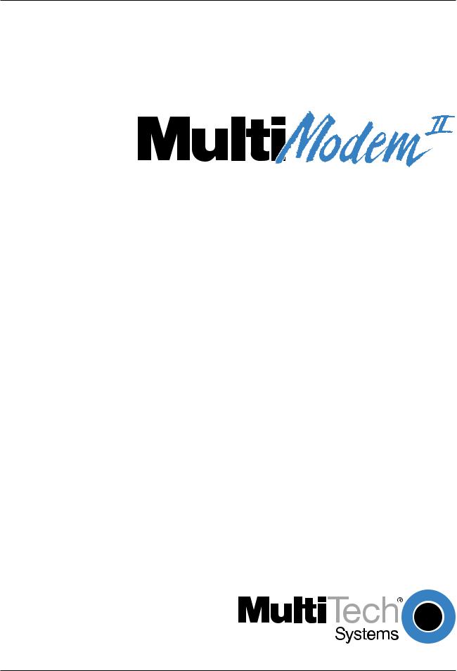
3.For BA: Connect the modem to a dial-up line by attaching the RJ-11 telephone cord (provided with your unit) to the LINE connector on the modem and to a dial-up wall jack.
PHONE LINE |
EIA RS232C |
ON |
|
|
VOLUME
 OFF
OFF
POWER
Figure 2-1. MultiModemBA Connections
The LINE connector can be used for a dial-up connection or a 2-wire leased-line connection.
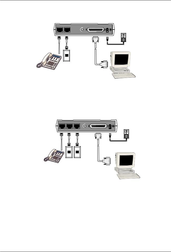
3.For BL: Connect the modem to either a dial-up line or lease-line.
To connect the modem to a dial-up phone line, attach the RJ-11 telephone cord (provided with your unit) to the PSTN connector on the modem and to a dial-up wall jack.
To connect the modem to a leased line, attach the RJ-11 telephone cord (provided with your unit) to the LEASE connector on the modem and to a leased line wall-jack.
PHONE PSTN LEASE |
EIA RS232C |
ON |
|
|
|
VOLUME |
|
OFF |
|
POWER |
Figure 2-2. BL Connections
The PSTN connector is used for a dial-up connection.
The LEASE connector can be used for a 2-wire or 4-wire leased-line connection.
4.Attach the EIA RS-232C connector on the modem to the serial port on your computer or terminal with an RS-232 (or V.24) cable (you supply).
5.To connect a telephone set to the modem (optional) plug one end of an RJ-11 phone cord into the PHONE connector on the modem, and plug the other end into your telephone.
6.Attach the AC Power transformer provided with your unit to the POWER connector on the modem and to a live AC outlet.
Note: Only apply power to the modem using the power transformer provided with your unit. Use of a power supply not designed for your unit could result in damage to your modem and will void the warranty.
7.Apply power to the unit by setting the ON/OFF switch at the rear of the modem to the ON (Up) position.
Multi-Tech Systems, Inc. MT2834BA/BL Series User Guide |
15 |

Chapter 2 - Installation and Connection
2.3Installing PhoneTools, the Data Communications Software
Data communications software is designed to send and receive messages. Multi-Tech includes a data communications software program, PhoneTools, with your modem. However, the modem will work with any data communications software.
To install PhoneTools, insert the MT2834BA/BL CD in you CD-ROM drive and click the PhoneTools icon. You will be asked to choose your language. The software will then automatically load onto your PC.
2.4Is Your Modem Ready for Use?
As soon as you have connected power to the modem, if you are an experienced modem user, you may simply want to check your modem’s settings for data compression, error correction, and so on. You may find that you can get moving quite quickly if you just issue an ATL5, ATL6 and an ATL7 command. These commands list how your modem is currently configured. If you come across a setting you’re unsure of, refer to Chapters 5 and 6 of the User Guide for AT command and S-Register explanations and defaults.
If you’re a novice, refer to Chapter 3 of the User Guide to learn about the basics of data communications.
Multi-Tech Systems, Inc. MT2834BA/BL Series User Guide |
16 |

Chapter 3 - Software Configuration and Modem Basics

Chapter 3 - Software Configuration
3.1Introduction
Chapter 2 described the installation of PhoneTools, a communications software. If you are using a different software package, there are some points you should take into consideration. Since your communications software configuration is affected by the capabilities of your computer, this chapter begins with a discussion of the limitations of some serial ports and how to identify them. It then discusses communications configuration in general and recommends settings specifically for the MultiModem. The last section of this chapter walks you through the basics of using your modem.
3.2Configuring Your Software
Communications software must be configured to work with your modem, your computer, and the remote system it is calling. Fortunately, most communications programs make the process easy by providing a default initialization string for your modem as well as defaults for most of the other required parameters.
3.2.1Configuring Software for Your Modem
Because remote computers may have different connection requirements such as speed, number of bits, parity, log-on sequences, etc., communications software is typically configured by sessions, each session having a unique configuration for a given connection. Most communications programs, however, have a separate modem configuration menu because modem configurations rarely change from session to session.
The most important configuration is the modem initialization string. This is a sequence of commands the software uses to configure the modem when the communications software is loaded or when a session begins. Always begin the initialization string with the ATtention command AT, then follow it with the modem reset command, &F. Issuing a reset command before other commands ensures that you are starting with a known state.
The rest of the commands in the initialization string depend on the capabilities of the modem and what you want it to do. Some older communications programs require you to create the initialization string by yourself. Most modern communications programs, however, provide you with a ready-made initialization string that is automatically selected when you choose your modem model from a list. It is a poor idea to use an initialization string intended for another modem, especially one from another manufacturer, because modem capabilities and command implementations vary from modem to modem. However, if your MultiModem does not appear on a modem list, you may use the MultiModemII initialization string.
3.3PC Initialization Strings
We recommend the following initialization string for a MultiModem connected to a PC-compatible computer when sharing a line with a telephone:
AT &F X4 S0=0 ^M
This string resets the modem to the factory default settings, selects extended result codes with NO DIAL TONE and BUSY, and turns off auto-answer. ^M must end every string sent to the modem from software. It is the ASCII code for the RETURN key on most keyboards, and the default code for the carriage return character in the modem and most communications programs. The carriage return character is defined in the modem in S-register S3; if you change it, you must also change the carriage return character code used in your communications software. If you send a command directly to the modem in terminal mode rather than indirectly through communications software, you must end the command string by pressing the RETURN key (<CR>) instead of adding ^M to the string.
The following initialization string is for a MultiModem on a telephone line that functions solely as a
DATA LINE:
AT &F X4 S0= 2 ^M
Multi-Tech Systems, Inc. MT2834BA/BL Series User Guide |
18 |

Chapter 3 - Software Configuration
3.3.1Changing Default Parameters
By default, the modem will answer after the first ring and try to communicate with a modem on the other end of the line. If you have one telephone line for voice, fax, and modem communications, the modem may attempt to answer all incoming calls, voice as well as data. To change auto-answer to default off, open your communications program and type the following string in the terminal window:
AT &F S0=0 &F9 &W0 <CR>
This string selects the factory default parameters, then turns auto-answer off and stores that setting, along with all other current parameters, in nonvolatile memory. The &F9 command causes the modem to load the values from nonvolatile memory the next time it receives the &F command. You will use the same initialization string as before:
AT &F X4 ^M
But now the modem will load the values stored in nonvolatile memory when you turn on the modem and when you issue the ATZ or AT&F reset commands.
Note: Because it clears the command buffer, you should not use ATZ in an initialization string.
3.3.2Other Parameters
The default values for the other parameters in modem configuration menus rarely need changing. They typically include the dialing prefix (ATDT for touch-tone service and ATDP for rotary service), the dialing suffix (^M), the hang-up string (+++ATH0^M), and response messages (RING, NO CARRIER, BUSY, etc.). Communications software with a host mode might also include an autoanswer string (AT S0=1^M).
3.4Configuring Software for Your Computer
You must configure your communications software to match your computer’s configuration. If the modem is connected to the COM2 serial port, you must tell the software you are using COM2. Another important parameter is the serial port baud rate. This is the speed at which your modem communicates with your computer, not the speed at which your modem communicates with another modem. When V.42bis data compression is enabled, you must have a serial port baud rate four times the transmission speed of the modem to fully optimize compression.
Multi-Tech Systems, Inc. MT2834BA/BL Series User Guide |
19 |

Chapter 3 - Software Configuration
3.5Modem Basics
You control your modem by issuing AT commands, setting S-Registers, and setting DIP-Switches. You can easily change the settings of your DIP-Switches, as they are located on the right side of your modem’s chassis. Right now your modem is set up for the most typical user application, that is, as a traditional modem set to make a dial-up call to a remote installation where the call is answered automatically; therefore, you shouldn’t need to change the DIP-Switches. (If however, you know that your application does not follow this profile, please refer to Chapter 8 for full details on DIP-Switch settings.)
While you may operate your modem manually, it is more likely that you will use your data communications software to either:
•enter “terminal” mode, where you can “speak most directly” to the modem by issuing AT commands, or to
•launch a datacomm session through a set of modem configurations which you select and then associate with a target telephone number. Once you have created, saved, and named this set of information according to your connection needs and your datacomm software’s conventions, the software then simplifies your dialing because you needn’t re-configure your modem, nor run the risk of mistakenly keying-in incorrect information.
Either way, you need to understand that an AT command is the method by which your modem is controlled, and must therefore prefix nearly all commands. AT stands for attention, and alerts the modem that a command follows. You may enter these commands with either upperor lowercase characters. Entering AT automatically sets the modem’s serial baud rate to match your computer’s and also sets the modem’s parity. It also clears the modem’s command buffer.
Once you’re in terminal mode, enter AT followed by <CR> to check whether your modem is operational. If everything’s fine, your modem will respond OK. (Note: refer to Chapter 4 for additional details on Dialing, Automatic Answering, Dial Back-Up and Automatic Leased Line Restoral.)
3.5.1Simple Operations
You can dial a number by using the ATD command and the phone number of the modem with which you wish to connect, e.g., ATD6127853500. Your modem will dial the number, and hear a “scrambling” noise as the modem negotiates the kind of connection it can make, and once the modems have settled on a common connection, you will receive a connect message on your computer’s video display. As the modem dials and connects, you may notice changes across its front LED panel: the OH (Off Hook) LED lights to let you know the modem is operating as if you had picked up the handset to a phone. The CD (Carrier Detect) LED lights to let you know the modem has detected a device it can connect to. A speed LED lights to let you know at which speed the connection has been made.
To hang up a call, enter +++ATH<CR>. Your modem will return on hook, just as if you had returned a phone’s handset to its cradle. Notice also that the OH, CD and speed LED’s are no longer lit. Your video now displays OK, signifying that your modem is ready for your next command.
3.6The Answer/Originate - Voice/Data Toggle Switch
Located on the front of the modem is a Voice/Data "toggle" switch with Originate/Answer capabilities. This switch enables the modem to automatically dial a phone number stored in the N1 location of memory whenever this switch is toggled. (Note that you must first enter AT$VD1&W0<CR>. This command string enables Voice/Data dialing when the Voice/Data toggle switch is activated.)
If you are "Manually" dialing with an attached telephone device (and not with your keyboard), your modem originates when toggled in that position (DOWN); and if you are "Manually" answering (modem is not configured to automatically answer via S-Register S0 setup), the modem answers an incoming call when toggled in that position (UP).
Multi-Tech Systems, Inc. MT2834BA/BL Series User Guide |
20 |
Chapter 4 - Manual Dial and Automatic Answer

Chapter 4 - Manual Dial and Automatic Answer
4.1Introduction
We’ll assume that yours is the very common application, where you are using a modem to dial up a remote computer. The modem has been factory preset for originating a call to a compatible 33,600 bps modem (also set up for hardware flow control, V.42 error correction, V.42bis data compression and CTS/RTS operation). If the answering modem is not set up similarly, the modem automatically adjusts to the appropriate protocol.
4.2Dialing/On-Line/Answering
There are several basic steps for “originating” and “answering” in data communication mode:
1.Load communication software
2.Dial
3.Establish On-Line connection
4.Terminate Call
A simple way to dial is from the keyboard of your computer or terminal. You enter a command on the keyboard to tell the modem to dial.
If you use a sophisticated communications software package, the software tells you to enter phone numbers and other information. If this is the case, the software, and not you, gives the dialing commands to the modem. All of the commands, option registers and intelligent features of the modem is taken care of by the software.
If you are giving commands directly to your modem (and not through your software), each command must begin with AT (ATtention Characters). AT characters may be entered in upper or lower case.
Entering AT automatically sets the modem’s speed to match the speed of the computer or terminal, and also sets the modem’s parity.
The AT characters alert the modem that a command follows. The AT Command can also be used to clear the command buffer, by simply typing AT and hitting RETURN.
The letter D in a command causes the modem to dial the numbers immediately following it (e.g., ATD6127853500). You have a choice of either pulse (ATDP) or tone (ATDT) dialing methods.
The modem responds with “CONNECT” on your video display after the number is dialed and a connection signal is detected. The modem is now in “On-Line” mode, and is ready to communicate with a host site.
If no connection signal is detected within 45 seconds (this time period can be adjusted by S-Register S7), the modem goes On Hook/hangs up and returns to Command mode. At this point, your video displays “NO CARRIER”.
Enter +++ATH to Hang Up On-Line (bring modem on-hook), and terminate the modem's On-Line mode. At this point, your video displays “OK”.
In addition to the call originating capabilities, the modem can also automatically answer incoming calls. You need not be present. You can, however, control the situation by configuring the modem to either answer or not to answer, or to answer after a specified number of rings. This is done by setting the value of S-Register S0 (modem defaults to automatically answer an incoming call after one ring). Refer to Chapter 6 for S-Register details.
Multi-Tech Systems, Inc. MT2834BA/BL Series User Guide |
22 |

Chapter 4 - Manual Dial and Automatic Answer
4.3Automatic Leased Line Restoral Operation
When the modem is in Dial Backup mode, it periodically checks the leased line to see if it's operational and tries to restore the leased line if possible. S-Register S18 determines how often restoral attempts occur. The default for S18 is 30 minutes, and can be set in one minute increments from 10 to 255 minutes. Setting the restoral attempts under 10 minutes causes excessive breaks in the dial-up operation.
Note: both local and remote modems must have S-Register S18 set identically. Refer to Chapter 6 for more information on S-Register S18.
4.4Manual Dial Backup Call Termination
With your modem in leased line mode (DIP-Switch #10 in the DOWN position) and with dial backup operation in process, there are two ways to manually terminate the dial backup call (other than automatic leased line restoral). In each case, you will try to establish the leased line connection because it is back in operating condition. The methods of dial backup call termination are:
1)Manual Control. The "Voice/Data" switch can be used to change from a dial back line to leased line by toggling down once. When that is done, the modem tries the leased line connection, and, if it is good, the modem disconnects the dial back call and establishes a leased line connection.
2)DTR Control. If DTR (Data Terminal Ready) is turned off for 50 milliseconds or more, a disconnect occurs. This is probably the most common method used by computer systems at the automatic answer end of the line to cause the answering modem to disconnect after toggling off procedures.
4.5Dial Backup and Leased Line Restoral
The dialing associated with the MultiModem, when in leased line with dial-back mode, involves placing a call from the originating modem due to a leased line failure.
After a preset period of time (determined by S-Register S18), the modem automatically tries to restore the leased line.
The parameters used to determine if a leased line is down (so automatic dial back can occur), is based on the modem doing a “retrain” on the leased line due to an error condition in the transmission. An error condition is defined as a "hit" on the line (the Carrier gets interrupted).
The retrain is a "handshake" procedure between the modems to establish the Carrier again. If the retrain fails, both modems (originate and answer modems) start their Dial-back timers. The time is determined by S-Register S19 settings. The S19 default setting is one minute. During that minute, the originate modem tries to establish the leased line link. If the leased line is established during that time, the timer is cleared and everything is back to normal. If the timer expires, the modems goes to dial-back mode.
The purpose of the timer for the Answer modem is to determine when it accepts a dial-up call. When both timers have expired and the leased line has not been established, the dial-back procedure starts. The number dialed is the one stored in location N9 of the originate modem's phone number memory. In the preparation for proper dial-back operation, enter the proper number in the N9 location using the commands detailed in Chapter 5. Keep in mind that the number also can be dialed in V.25bis Command mode.
Multi-Tech Systems, Inc. MT2834BA/BL Series User Guide |
23 |

Chapter 4 - Manual Dial and Automatic Answer
4.6Dial-Up Operation
When your modem is used as a dial-up modem (DIP-Switch #10 in the UP position), it can both originate and answer calls. To originate calls, you use the automatic dialing capability of the modem's Command mode.
To do this, use the computer or terminal keyboard to enter a few command letters, followed by the phone number you wish to dial. If you have a computer with sophisticated communications software, you may end up talking back and forth with the software, and the software will take care of talking to the modem.
It is still possible, however, to dial your data calls using a telephone set. There are few reasons why you would want to do this, but if you have a need to use the telephone set to dial, we explain how in the next section. We will delay our coverage of Command Mode autodialing, and all other Command Mode features, until Chapter 5.
4.7Manual Call Origination
You can use the modem to both originate and answer calls. To originate calls in Asynchronous mode, you will most likely use the modem's Command mode, and give the modem automatic dialing commands (we will delay our discussion of the Command mode until Chapter 5). When using your modem in Synchronous mode, the Command mode is disabled, so you must automatically dial your calls with a telephone set. To use manual dialing, you first connect an ordinary telephone set (either touch tone or rotary dial) to the modem'sPHONE Jack, if you have not already done so. Next, set the speed selection, (DIP-Switches #13 and #14), to the speed at which you wish to communicate. These DIP-Switches are located on the side of the modem. (Refer to Chapter 8 for DIP-Switch settings.) Your computer or terminal may be set for up to 115,200 bps.
When your telephone set is connected, you can use it to dial the modem you wish to call. Simply dial the number, and then listen to the dialed modem's answer tone. When you hear it, press the Voice/ Data switch on the front of the modem down (to the Originate position). You don't have to hold it down. Just "toggle it" (press it once and let it go). Once you press the switch, the tone you hear should change to another pitch, or change into a rough-sounding scrambled noise. You then replace the telephone handset in its cradle, and your data communications begins.
Note that the modem may call manually via the keyboard command ATD, or by pressing the Voice/ Data switch on the modem's front panel downward. To force the modem to automatically answer calls, either type ATA, or press the Voice/Data switch on the modem's front panel upward.
Multi-Tech Systems, Inc. MT2834BA/BL Series User Guide |
24 |

Chapter 4 - Manual Dial and Automatic Answer
4.8Automatic Answering
The modem can be used as an automatic answering modem. No special modifications or settings are required other than making sure that the Auto-Answer select switch is set to Auto-answer enabled (DIP-Switch #5 UP).
The modem, when in its idle state, is set for Originate mode frequencies. An incoming ring signal automatically switches the modem into Answer mode.
You can program the modem to answer a call after a certain number of rings using S-Register S0 (see Chapter 6). Refer to Section 4.10 for the handshaking procedures used by the modem when in automatic answer mode.
In many originate-only applications, you may wish to disable the automatic answer capability of the modem. If a telephone set is connected to the modem, you may wish to receive incoming calls in a voice mode for normal voice conversation. If auto-answer is not disabled, all incoming calls are answered by the modem, preventing voice communications. To disable automatic answer, place DIPSwitch #5 to the DOWN (Disable Auto Answer) position (refer to Chapter 9).
Another way to disable automatic answer is to use S-Register S0 to configure the modem to answer on the nth ring, where n equals zero (0). Another alternative is to have the modem answer after five or six rings, which gives you time to answer it manually if you wish. (See Chapter 6 for S-Register information.)
4.9Manual Answering
We have shown that the modem can automatically answer incoming calls. The MultiModem can also answer manually, under your control. The most typical application involves you and another person, who, after carrying on a voice conversation, want to convert to data communications between your modems without having to hang up and dial again.
The problem here is that both modems are in originate mode. For two modems to communicate, one of them must be in originate mode and the other must be in answer mode. The solution here is to force either one of the two modems to Answer mode, and the other to Originate mode.
The modem can be forced into either Answer mode or Originate mode by using the Voice/Data switch on the front of the modem.
In our example, let's say that you and your friend Bill have just had a voice conversation. Both of you have your telephones connected to your modems, and your modems are connected to computers or terminals. Set the speed switches to the proper speed on both modems. To switch to Data mode from Voice mode, you would switch the Voice/Data switch Down (to the Originate position), and Bill would switch his up to Answer. This switches your modem to the originate on-line mode, and Bill's to the Answer on-line mode. You would both then hang up your telephone handsets, and continue the conversation via your keyboards.
Multi-Tech Systems, Inc. MT2834BA/BL Series User Guide |
25 |

Chapter 4 - Manual Dial and Automatic Answer
4.10 Handshaking Details
This section briefly explains what happens between two modems in a normal call. We are assuming that there are MultiModems at both the originating and at the answering end of the telephone line. (If other brands of modems are used with our modems, they will still communicate, but each manufacturer tends to use slightly different delay timings and sequences, and many of the brands vary in their LED designations.)
When a call is dialed from the originating modem, the called modem responds to the ringing by switching into Answer mode and by turning on its RI (Ring Indicator, RS-232C/V.24 Pin 22) signal as the rings are detected.
Note that in order for the called modem to be able to answer the call, it must have a high DTR (Data Terminal Ready) signal. This signal comes from the computer or terminal to which it is attached, on RS-232C Pin 20.
When the called modem answers the call, its OH (Off Hook) circuit comes on and the ringing stops. Two seconds after the call is answered, the called modem begins transmitting its answerback tone.
The originating modem, which has been off hook and waiting for the answerback tone, turns on its transmitter when it hears the tone. Then after a one second delay, the orignating modem's CD (Carrier Detect) comes on.
The called modem then responds to the originating modem by turning on its CD (Carrier Detect) signal, and the handshaking is completed.
Note: With the modem in Reliable or Auto-Reliable mode, some additional handshaking takes place. This is explained in Section 5.4.8.
4.11 Call Termination
There are a number of ways to terminate a call, or simply stated, hang up. They are:
1)Command Mode Control. To terminate a call by Command Mode, enter +++ATH then RETURN; or, send a BREAK signal followed by ATH and a RETURN.
2)DTR Control. If DTR (Data Terminal Ready) is turned off for 50 milliseconds or more, a disconnect occurs. This is probably the most common method used by computer systems at the automatic answer end of the line to cause the answering modem to disconnect after logging off procedures.
3)Loss of Carrier. After a data connection is established, the modem disconnects if a loss of carrier occurs for 700 milliseconds (0.7 seconds) or more. Note that one cause of carrier loss would be if one of the modems disconnect normally.
4)Abort Timer.
Answer Mode: When OH (Off Hook) comes on, the called modem starts a forty-five-second timer and waits for a carrier signal from the originating modem. If carrier is not detected within this period, the modem disconnects (hangs up) and is ready for another call.
Originate Mode: The abort timer functions the same as in answer mode, except that the timer begins after the modem has completed dialing, instead of when it first goes off hook. It is possible to change this forty-five second wait period to any other value (from 0 seconds up to 255 seconds), or to disable the timer completely by re-configuring S-Register S7 (see Chapter 6).
5)Inactivity Timer. Causes the modem to disconnect if no data is transmitted or received for a specified time. The timer is restored any time a character is passed through the serial port in either a send or receive state. This timer runs in both normal or reliable connections and is controlled by S-Register S30. The Inactivity Timer can be disabled by setting S30 to 0, which is the factory default setting.
Multi-Tech Systems, Inc. MT2834BA/BL Series User Guide |
26 |

Chapter 5 - Command Mode

Chapter 5 - Command Mode
5.1Introduction
AT commands are the means by which you, and your communications software, are able to communicate with and configure your modem. They enable you to establish, read, and modify parameters in addition to dialing. The following provides both a summary and a detailed explanation of the AT commands recognized by the MultiModem.
5.1.1AT Command Editing
The BACKSPACE key on your keyboard can be used to edit characters in the AT command line. An AT command is not executed until the RETURN key is pressed. The BACKSPACE key erases the previous character for reentering.
The BACKSPACE key does not erase the AT characters once they are entered. If your keyboard has no BACKSPACE key, CTRL-H does the same thing. The character recognized by the modem as BACKSPACE may be changed to any other ASCII character with S-Register S5.
If you wish to cancel an entire command that has been entered but not yet executed, enter CTRL-X. This also clears the command buffer. The effect is the same as backspacing to cancel the entire command, only quicker.
Characters entered in a command are stored in the modem's Command Buffermemory( ) until executed by hitting RETURN. The Command Buffer's capacity is sixty characters. The Attention Characters AT do not count in the sixty allowed Command characters. Spaces, which may be used for increased display readability, may be used when entering a command, but are not stored in the Command Buffer and are not counted in the sixty allowed characters. Hyphens, parentheses, etc. are not allowed.
If the sixty character limit is exceeded or if invalid characters are entered, the Command Buffer automatically erases, and an ERROR message appears. You would then re-enter your command within the sixty-character maximum, using only the allowed characters.
5.1.2Functional Modes
The MultiModem can be in one of two functional states (see Figure 4-1). These are "Command mode" and "On-line mode". (There is also an in-between state, "Wait-for-Carrier", where the modem is out of Command mode but not yet really On-Line.
When the modem is initially powered up, it is in Command mode and is ready to accept commands from your keyboard or software. The modem enters On-line mode after dialing, making a connection with another modem, and then detecting a valid carrier signal. If no carrier is detected within a certain time frame, the modem abandons the call and re-enters Command mode.
Once on line, the modem exits On-line mode if one of two conditions is met. If the carrier is lost or intentionally dropped, the modem hangs up and re-enters Command mode. Also, if the modem recognizes the Escape sequence for which it is configured (i.e., either the Escape characters in the serial data stream, the Remote Escape characters in the modulated data stream, or the Break signal), the modem will exit On-line mode, retain the datacomm link, and enter Command mode.
You can force the modem into On-line mode without dialing by sending the ATD or ATA command to the modem.
Multi-Tech Systems, Inc. MT2834BA/BL Series User Guide |
28 |

Chapter 5 - Command Mode
|
|
|
|
|
|
|
|
|
COMMAND |
|
|
|
|
+++AT |
|
|
|
|
|
|
|
|
|
|
|
|
|
|
|
|
|
|
|||||
|
|
|
|
|
|
|
|
|
MODE |
|
|
|
|
|
|
|
|
|
|
|
|
|
|
|
|
|
|
|
|
|
|
|
|
|
|
||
|
|
|
|
|
|
|
|
|
|
|
|
|
|
|
|
|
|
|
|
|
|
|
|
|
|
|
|
|
|
|
|
|
|
|
|
|
|
HANG |
|
|
|
|
Dial (D or A) command, |
|
||||||||||||
|
UP |
|
|
|
|
or incoming phone call |
|
|||||||||||
|
|
|
|
|
|
|
|
|
|
|
|
|
|
|
|
|
|
|
|
|
|
|
|
|
|
|
|
|
|
|
|
|
|
|
|
|
|
|
|
|
|
|
|
|
|
|
|
|
|
|
|
|
|
|
|
|
|
|
|
|
|
|
|
|
|
|
|
|
|
|
|
|
|
|
|
|
|
|
|
|
|
|
|
|
WAIT FOR |
|
|
|
|
|
|
|
|
|
|
|
|
|
|
|
|
|
|
CARRIER |
|
|
|
|
|
|
|
|
|
|
|
|
|
|
No carrier |
|
|
|
|
|
|
|
|
|
|
|
||
|
|
|
|
|
|
|
Carrier detected |
|
||||||||||
|
|
|
|
|
detected |
|
|
|
||||||||||
|
|
|
|
|
|
|
|
|
|
|
|
|
|
|
|
|||
|
|
|
|
|
|
|
|
|
|
|
|
|
|
|
|
|
|
|
|
|
|
Carrier lost |
|
|
ON-LINE |
|
|
|
AT0 Command |
|
|
||||||
|
|
|
|
|
|
|
|
|
||||||||||
|
|
|
|
|
MODE |
|
|
|
|
|
|
|
|
|||||
|
|
|
|
|
|
|
|
|
|
|
||||||||
|
|
|
|
|
|
|
|
|
|
|
|
|
|
|
|
|||
|
|
|
|
|
|
|
|
|
|
|
|
|
|
|
|
|
|
|
Figure 5-1. Functional Modes
5.2Summary of AT Commands
A wide variety of autodial operations and modem options can be controlled when the modem is in Command Mode. Remember, nearly all commands begin with AT.
These commands are organized into several functional groups. An alphabetical summary of commands is provided in Appendix D.
HOW TO |
COMMANDS |
|
DIAL |
D |
Dial |
|
A: or : Continuous Redial |
|
|
$D |
DTR Dialing |
|
$VD |
Voice/Data Dialing |
|
N |
Dial a Stored Number |
MODIFY DIALING |
P/T |
Pulse/Tone Dialing |
PROCEDURES |
&P |
Set Pulse Dial Ratios |
|
, |
Automatic Pauses in dialing |
|
Y |
Long Space Disconnect |
|
W |
Wait for New Dial Tone |
|
; |
Return to Command Mode After Dial |
|
|
Command |
|
R |
Reverse Mode of Operation |
|
! |
Flash On Hook |
|
$ |
AT&T "Calling Card" Tones |
|
@ |
Quiet Answer |
MEMORIZE PHONE |
|
|
NUMBERS |
D...N |
Store Phone Numbers |
|
NN |
Number Linking |
|
L |
List Numbers Stored in Memory |
Multi-Tech Systems, Inc. MT2834BA/BL Series User Guide |
29 |

Chapter 5 - Command Mode
STORE MODEM |
&F |
Load Factory Defaults |
CONFIGURATIONS |
&W |
Store Configuration & S-Register |
AND DEFAULTS |
|
Parameters |
|
Z |
Reset Modem |
|
V |
Result Code Terse/Verbose |
|
$SP |
UNIX/"Spoofing” |
|
&M |
Synchronous/Asynchronous Mode Select |
|
&X |
Synchronous Transmit Clock Select |
CONFIGURE |
Q |
Result Codes Enable/Disable Response |
COMMAND |
&Q |
Result Code Selection |
RESPONSES |
E |
Echo Command Characters |
|
V |
Result Code Terse/Verbose |
|
X |
Result Code...Basic/Extended/Call Progress |
CONDITION |
&G |
Guard Tones |
PHONE LINE |
M |
Monitor Phone Line |
|
&T |
Remote Digital Loop Signal |
|
#T |
Enable/Disable Trellis Coded Modulation |
|
B |
Bell/V.21 Tones |
|
#F |
Fallback When On-Line |
|
&CD |
Cleardown at Disconnect (2834 Series only) |
|
#A |
Auto-Speed Detect |
CONTROL RS232C |
&C |
Carrier Detect Control |
INTERFACE |
&D |
Data Terminal Ready Control |
|
&R |
Clear To Send Control |
|
&S |
Data Set Ready Control |
|
&RF |
CTS/RTS Control |
|
&SF |
DSR/CD Control |
CONFIGURE |
&E0 |
Normal Mode |
ERROR |
&E1 |
Auto-Reliable Mode |
CORRECTION |
&E2 |
Reliable Mode |
|
#L0 |
Negotiate V.42 Mode During Handshake |
|
#L1 |
MNP On/LAPM Off |
|
#L2 |
LAPM On/MNP Off |
|
#L3 |
Direct LAPM/Phase Out Handshake |
|
$A |
Auto-Reliable Buffering |
|
$F |
Enable/Disable Auto-Reliable Fallback Character |
|
$R |
Retransmit Count |
|
$E |
Error Correction at 300 bps |
CONFIGURE |
&E3 |
Flow Control Disabled |
FLOW CONTROL |
&E4 |
Hardware Flow Control |
|
&E5 |
Xon/Xoff Modem-Initiated |
|
&E6 |
Xon/Xoff Modem Responds/No Pass-Through |
|
&E7 |
Xon/Xoff Modem Responds/Pass-Through Allowed |
|
#X |
Send Single/Multiple Xoff Characters |
|
&E8 |
Enq/Ack Off |
|
&E9 |
Enq/Ack On |
|
&E10 |
Normal Mode Modem Flow Control Off |
|
&E11 |
Normal Mode Modem Flow Control On |
|
&E12 |
Computer-Initiated/Off |
|
&E13 |
Computer-Initiated/On |
|
&BS |
Maximum Block Size |
|
$EB |
10/11 bit Asynchronous Format |
|
#P |
Parity Selection |
Multi-Tech Systems, Inc. MT2834BA/BL Series User Guide |
30 |
Loading...