


POWER
AMPLIFIER OWNER’S
MANUAL

POWER AMPLIFIER OWNER’S MANUAL
Introduction
|
CONGRATULATIONS... |
|
ENGLISH |
on your purchase of a new MTX Audio |
|
Thunder Amplifier! MTX has long been the |
||
|
||
|
industry leader in mobile enclosures and |
|
|
speakers, and we have reached new heights |
|
|
with the development of the new MTX |
|
|
Thunder amplifiers. You couldn’t have chosen |
|
|
a more reliable, powerful, or better perform- |
|
|
ing amplifier. In fact, we back up every |
|
|
Thunder amplifier with a three-year warranty |
|
|
if installed by an authorized MTX Audio retail- |
|
|
er (see the warranty statement). |
|
|
Your new MTX Thunder amplifier was |
|
|
designed, built and thoroughly tested at our |
|
|
state-of-the-art electronics manufacturing |
facility. We manufacture every amplifier using the latest Intelligent Surface Mount Technology. Some of the advantages of the new design are its significant improvements to the amplifier’s electrical and mechanical properties. ISMT devices feature substantially shorter internal and external lead lengths. This reduces stray capacitance and inductance, which results in cleaner and more accurate musical reproduction with significantly less noise interference. The ISMT mounter produces amplifier boards with smaller and lighter components, which are more resistant to vibrations inherent in the automotive environment.
A word about power ratings. It is important for you to know how they stack up. MTX has chosen the most honest, most conservative way to rate our amps. We show you the RMS power, at 12.5 volts, and dynamic power at 14.4 volts. However, we go above and beyond the call of duty. We test each amplifier. The technician records the “actual” power output, and records this number on your Certified Performance Certificate. The amplifier must meet or exceed the rated specification before we’ll ship it. No questions. No exceptions.
We want to ensure you get continuous high performance from your MTX Thunder amplifier, so we recommend that you have it professionally installed by your authorized MTX dealer.
HOW TO USE THIS MANUAL
If you are installing this amplifier yourself, we recommend that you read the manual cover-to-cover before you install it. Familiarize yourself with the features and details on the input and output panels. Make sure you have all the equipment you need. Then follow the step-by-step installation instructions included. Sample installation diagrams may be found on our website:
mtx.com
If you have any questions, write or call us:
MTX Audio
4545 E. Baseline Rd. Phoenix, AZ 85042 602-438-4545 • 800-CALL MTX technical@mtx.com
mtx.com
Please take a moment to register your purchase on-line at mtx.com.
Please also record the serial number of your amplifier in the space provided below and keep this manual for future reference, as well as your sales receipt as proof of ownership. (The serial number of your amplifier is marked on the bottom of its metal chassis.)
SERIAL NUMBER:
DATE OF PURCHASE:
Features
• Thunder Amplifiers are Covered by One or More |
• Bridgeable Circuit Design |
|
|
of the Following United States of America |
• Buffered RCA Output for Daisy-Chaining |
|
Patents: #5,598,325, #5,631,608, #5,783,970 |
Multiple Amplifiers |
• |
Acoustically Seamless Turn-On/Turn-Off |
• Left and Right Individually Adjustable |
• |
Adjustable Input Sensitivity |
Input Sensitivity |
• Anti-Shock PCB Mounting Design |
• Patented Class A 100% Discrete Driver |
|
• |
High Powered Transformer |
Circuit Topology |
• Intelligent Surface Mount Technology |
• Patented Pure N-Channel Design |
|
• Nickel-Plated, Heavy Duty Terminal |
• Thunder EQ Bass Enhancement |
|
|
Block Connectors |
• Tracking RCA Crossover Output |
• Patented PWM MOSFET Switching Power Supply |
• Smart-Engage™ Auto Turn-On for Easy |
|
• Real Time Computerized Protection Circuit |
Integration with Factory Head Units When Using |
|
• Unique Rubber Insulated Iso-Feet™ |
Speaker Level Inputs (THUNDER342) |
|
• 12dB/Octave Stereo High Pass, 24dB/Octave |
• Speaker and Low Level Inputs (THUNDER342) |
|
|
Mono Low Pass Crossover |
|
Specifications
THUNDER342
•RMS Power measured at 12.5 Volts DC:
60 Watts x 2 into a 4 Ohm load with less than 0.1% Thd+N 120 Watts x 2 into a 2 Ohm load with less than 0.1% Thd+N 240 Watts bridged into a 4 Ohm load with less than 0.1% Thd+N
•Dynamic Power measured at 14.4 Volts DC:
85 Watts x 2 into a 4 Ohm load
170 Watts x 2 into a 2 Ohm load
340 Watts bridged into a 4 Ohm load
•Signal to Noise Ratio: ≥ 110dB A-Weighted
•Damping Factor: >200
•Frequency Response: 20Hz-20kHz ± 0.25dB
•Maximum Input: 8Vrms
•Thunder EQ: Variable Bass Boost (0-18dB) centered at 40Hz
•Crossover: Variable 40Hz to 200Hz, 12dB/Octave Stereo High Pass, 24dB/Octave Mono Low Pass, or Full Range
•Dimensions: 10.7" x 9.75" x 2.1" (27.2cm x 24.8cm x 5.3cm)
THUNDER502
•RMS Power measured at 12.5 Volts DC:
90 Watts x 2 into a 4 Ohm load with less than 0.1% Thd+N 180 Watts x 2 into a 2 Ohm load with less than 0.1% Thd+N 360 Watts bridged into a 4 Ohm load with less than 0.1% Thd+N
•Dynamic Power measured at 14.4 Volts DC:
125 Watts x 2 into a 4 Ohm load
250 Watts x 2 into a 2 Ohm load
500 Watts bridged into a 4 Ohm load
•Signal to Noise Ratio: ≥ 110dB A-Weighted
•Damping Factor: >200
•Frequency Response: 20Hz-20kHz ± 0.25dB
•Maximum Input: 8Vrms
•Thunder EQ:Variable Bass Boost (0-18dB) centered at 40Hz
•Crossover: Variable 40Hz to 200Hz, 12dB/Octave Stereo High Pass, 24dB/Octave Mono Low Pass, or Full Range
•Dimensions: 12.6" x 9.75" x 2.1" (32.1cm x 24.8cm x 5.3cm)
THUNDER942
•RMS Power measured at 12.5 Volts DC:
175 Watts x 2 into a 4 Ohm load with less than 0.1% Thd+N 350 Watts x 2 into a 2 Ohm load with less than 0.1% Thd+N 700 Watts bridged into a 4 Ohm load with less than 0.1% Thd+N
•Dynamic Power measured at 14.4 Volts DC:
235 Watts x 2 into a 4 Ohm load
470 Watts x 2 into a 2 Ohm load
940 Watts bridged into a 4 Ohm load
•Signal to Noise Ratio: ≥ 110dB A-Weighted
•Damping Factor: >200
•Frequency Response: 20Hz-20kHz ± 0.25dB
•Maximum Input: 8Vrms
•Thunder EQ: Variable Bass Boost (0-18dB) centered at 40Hz
•Crossover: Variable 40Hz to 200Hz, 12dB/Octave Stereo High Pass, 24dB/Octave Mono Low Pass, or Full Range
•Dimensions: 17.8" x 9.75" x 2.1" (45.3cm x 24.8cm x 5.3cm)
2
3
POWER AMPLIFIER OWNER’S MANUAL
Installation
Any deviation from the connection specifications recommended may cause serious damage to the amplifier, speakers and/or vehicle electrical system. Please double-check the connection before turning the system on.
1.Disconnect the vehicle’s negative battery connection.
2.Place your Thunder amplifier at the predetermined mounting location. Using a felt pen, mark the exact position of the mounting holes on the mounting surface. Set the amplifier aside. Use a sharp, precise blade to cut small circles in the carpet and padding around the four marks denoting your mounting holes to expose the metal underneath. Use a center punch to make an indentation in the metal to ensure that you drill the exact position for the screws. Drill the four holes as marked.
3.Temporarily mount your Thunder amplifier using the four (4) screws provided.
4.Run a power cable from the vehicle’s battery through the firewall and through the interior of the vehicle connecting one end to your Thunder amplifier’s +BATT terminal and connect the other end to the positive post on the battery.
Note: Install a circuit breaker/fuse within 18" of the battery. This effectively lowers the risk of severe damage to your vehicle should a short circuit ever occur in the audio system. Do not install the fuse in the fuse holder until all installation steps have been completed.
5.Find a good ground spot on the vehicle’s chassis and remove the paint to reveal bare metal at the contact point. Attach the ground wire to that contact point and connect the other end of the ground wire to the GND terminal of your Thunder amplifier.
6.Connect a Remote Turn-on wire from your source unit to your Thunder amplifier’s REM terminal (14 or 16 gauge wire). If your source unit does not have a dedicated Remote Turn-on lead, you may connect to the source unit’s Power Antenna lead.
7.Connect RCA cables from your source unit to your Thunder amplifier’s RCA input jacks. If RCA (low level) output is not available, connect the included speaker (high level) connector to the speaker wires from the source unit.
8.Connect your speakers to your Thunder amplifier’s speaker terminals using 12 gauge minimum speaker cable.
9.Double-check all the previous installation steps, in particular, the wiring and component connections. Securely mount the amplifier. If everything is in order, reconnect the vehicle’s negative battery connection and begin adjusting your amplifier.
Note: Be sure that the Gain Level on the amplifier is turned all the way down (counter clockwise) before proceeding with adjustments.
Common Oversights
•The battery ground should remain DISCONNECTED at all stages of installation.
•Do not begin drilling until you have put your Thunder amplifier aside. Using the amplifier as a drilling guide may cause irreparable damage to the amplifier and void your warranty.
•Do not route any wires underneath or outside the vehicle body.
•Route signal wires (RCAs from source unit, speaker wires, etc.) away from power wires (power, ground, etc.) to avoid ground loops and other sources of noise.
Adjusting the Gain
1.Turn the gain control on the amplifier all the way down.
2.Turn up the volume control on the source unit to approximately 3⁄4 of maximum.
3.Adjust the gain control on the amplifier until audible distortion occurs.
4.Adjust the gain control down until audible distortion disappears.
5.Follow steps 3-4 for other gain control settings if applicable.
6.The amplifier is now calibrated to the output of the source unit.
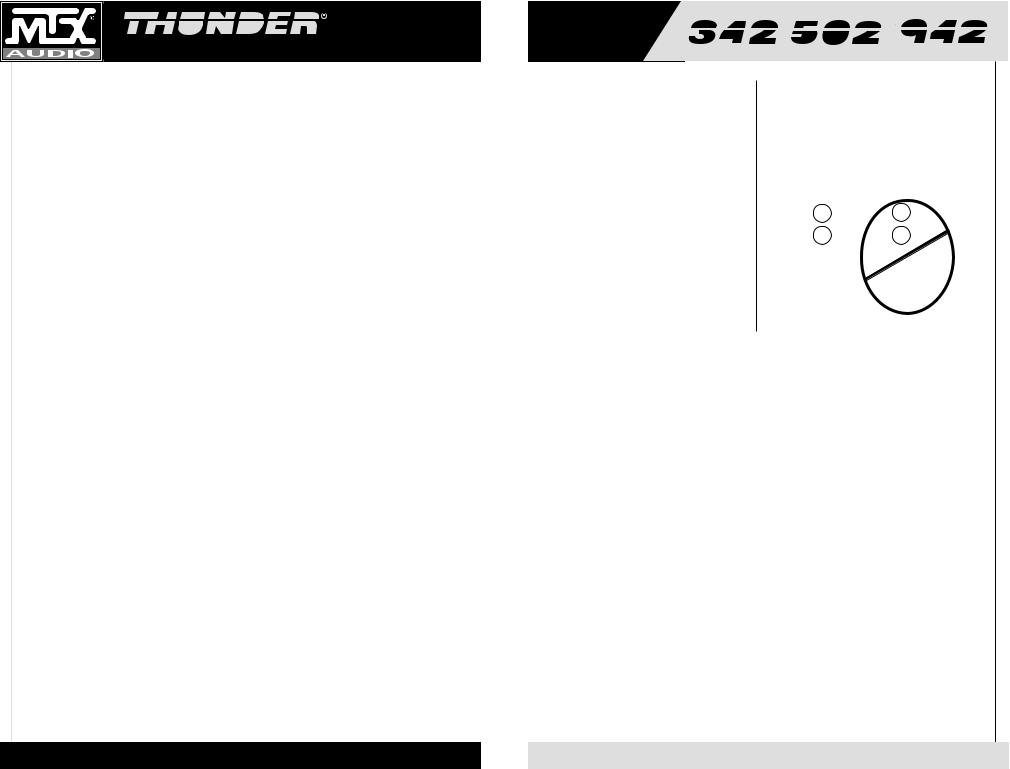
Typical Speaker
Wiring Configurations
Stereo Amplifier
Bridge Mode Application
Impedance Requirement
4 ohm bridge minimum
2 ohm stereo minimum
|
|
8 ohm |
|
|
|
4 ohm |
|
||||
|
|
8 ohm |
|
|
|
4 ohm |
|
||||
|
|
|
|
|
|
|
|
|
|
|
|
|
+ |
- - + |
|
|
+ |
- - + |
|
||||
|
L |
L R R |
|
|
L |
L R R |
|
||||
|
|
AMP |
|
|
|
AMP |
|
||||
Two 8 ohm Speakers |
Two 4 ohm Speakers |
||||||||||
|
|
|
|
|
|
|
not |
||||
OK ok
Troubleshooting Guide
Read this if you wanna be a do-it-yourselfer or give us a call at 800-CALLMTX.
PROBLEM |
CAUSE |
No LED indication |
No +12V at remote connection |
|
No +12V at Power connection |
|
Insufficient ground connection |
|
Blown power fuse |
LED on, no output |
Volume on head unit off |
|
Speaker connections not made |
|
Gain control on amplifier off |
|
Signal processing units off |
|
All speakers blown |
Output distorted |
Head unit volume set too high |
|
Amplifier gain set too high |
Balance reversed |
Speakers wired L + R reversed |
|
RCA inputs reversed |
Some balance reversed |
Some Speakers wired L + R |
|
reversed |
|
Some RCA inputs reversed |
Bass is weak |
Speakers wired out |
|
of phase |
|
Not using MTX woofers |
Blowing fuses |
Excessive output levels |
|
Amplifier defective |
SOLUTION
Supply +12V to terminal Supply +12V to terminal Verify ground connection Replace fuse
Increase volume on head unit Make speaker connections Turn up gain
Apply power to signal processor Replace speakers
Lower head unit volume
Lower amplifier gain
Wire speakers with correct orientation
Reverse RCA input
Wire speakers with correct orientation
Reverse appropriate RCA inputs
Wire with correct phase
Buy MTX woofers
Lower volume
Return for service
4
5

POWER AMPLIFIER OWNER’S MANUAL
1.Gain Controls – These controls are used to match the input sensitivity of the amplifier to the particular source unit that you are using. The controls are factory set to 1Vrms.
2.RCA Input Jacks – These RCA input jacks are for use with source units that have RCA or Line Level Outputs. A source unit with a minimum level of 200mV is required for proper operation. The use of high quality twisted pair cables is recommended to decrease the possibility of radiated noise entering the system.
3.Speaker Level Inputs – This input, found on the Thunder342 will allow the amplifier to operate from source units with speaker-level outputs. Output speaker leads from the source unit should be tied directly to the wire harness provided with the amplifier.
Wire harness color codes: |
|
Grey / Black = Source units right negative (-) |
White / Black = Source units left negative (-) |
Solid Grey = Source units right positive (+) |
Solid White = Source units left positive (+) |
With the Smart-Engage™ auto-turn circuit, a remote turn-on wire is not necessary when connecting the speaker-level input wire harness to a high powered source unit. The amplifier will automatically turn on when music is received.
4.Frequency Control – This control is continuously adjustable from 40Hz through 200Hz. Factory setting is at 40Hz.
5.Crossover Select – This switch determines what type of signal comes out of the amp. If you select high pass, the crossover slope is 12dB/stereo. If you select low pass, your crossover slope will be 24dB/mono. Available crossover frequencies are 40-200Hz.
6.Thunder EQ – This equalization circuit is used to enhance the low frequency response of the vehicle’s interior. With up to 18 dB of boost and centered at 40Hz, the Bass EQ can be adjusted to meet your own personal taste.
7.Compression Circuit – This new circuit, found on the Thunder942 and Thunder502, prevents the amplifier from going into clipping, even at high SPL levels. The compression circuit allows the listener to play the amplifier at high volume levels, yet protects the speakers against the potential damage that can occur during dynamic musical passages. The circuit is switchable on/off, for those SPL competitors who run their amplifiers into clipping on purpose. Warning: Damage to speakers may occur when the compression circuit is in the off position.
8.EBC 2 – The EBC, or Electronic Bass Control, allows a remote bass control to be adjusted from the driver’s seat. If the optional EBC is installed, the bass level will be able to be adjusted to overcome noise and other interference. With EBC 2 multiple amplifiers can be controlled. (Thunder942 and Thunder502)
9.RCA Output Jacks and Switch – These RCA outputs allow for a signal to be sent to other amplifiers in a daisy-chain configuration. You can select whether the signal should be high pass , low pass or full range. In low pass mode, the RCA outputs allow for multiple bass amplifiers to be level controlled using one EBC.
Input Panel Layout


6
7
POWER AMPLIFIER OWNER’S MANUAL
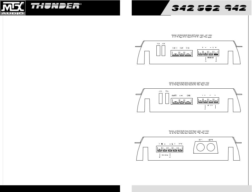
1. Fuses - For convenience, all amplifiers utilize ATC type fuses. For continued protection in the event that a fuse blows, replace the fuse only with the same value.
Caution: The power fuses on the amp are for protecting the amp against overdrive. To protect the vehicle’s electrical system, an additional fuse is required within 18" of the battery on the 12V+ cable.
Thunder342 - 20A x 2
Thunder502 - 30A x 2
Thunder942 -150 Amps (not supplied)
2. Power Terminal – This is the main power input for the amplifier and must be connected directly to the positive terminal of the car battery for the amplifier to operate properly. See the chart below for recommended cable sizes for each amplifier. Use caution when running this cable through the car. Try to avoid the input RCA cables, antenna cabling, or other sensitive equipment as the large amount of current flowing through this cable can induce noise into your system. It is also very important to have a tight connection to ensure maximum performance.
Thunder342 – 10 Gauge
Thunder502 – 6 - 8 Gauge
Thunder942 – 1/0 Gauge
3.Ground Terminal – A good quality ground is required for your Thunder Amplifier to operate at peak performance. A short length of cable the same gauge as your power cable should be used to attach the ground terminal directly to the chassis of the car. Always scrape or sand any painted surfaces to expose bare metal where the ground wire will attach.
4.Remote Terminal – All Thunder Amplifiers can be turned on by applying 12 volts to this terminal. Typically this voltage is supplied by a wire from the source unit marked “remote” or “electric antenna”.
5.Speaker Terminals – As shown in the wiring diagrams, be sure to observe speaker polarity through the system. Failing to wire the speakers in proper phase could result in a loss of bass response and/or poor overall sound quality. Caution: Thunder amplifiers are not recommended for loads below 2 ohms stereo or 4 ohms bridged.
6.Power LED (top of heatsink) - A lighted LED indicates that power has been applied to the amplifier. +12V from the battery to the +BATT terminal and +12V from a switched ignition or remote lead from a head unit. An unlighted LED indicates power has been removed or the amplifier has overheated. In the case of the overheat condition, the amplifier will turn back on after it cools down.
Output Panel Layout
8
9

POWER AMPLIFIER OWNER’S MANUAL
Introduction
FRANÇAIS |
FELICITATIONS... |
|
vous félicitant de votre achat d’un nouveau |
||
|
||
|
amplificateur MTX Audio Thunder! MTX a été |
|
|
depuis longtemps un leader dans l’industrie |
|
|
d’enclos mobiles et speakers, et nous |
|
|
sommes arrivés à un nouveau sommet avec le |
|
|
développement des nouveaux amplificateurs |
|
|
MTX Thunder. Vous n’auriez pas pu choisir |
|
|
d’amplificateur plus fiable, plus puissant ou |
|
|
meilleur. En effet ; nous garantissons pendant |
|
|
trois ans chaque amplificateur Thunder s’il est |
|
|
installé par un vendeur agréé (voir la |
|
|
garantie). |
|
|
Votre nouvel amplicateur MTX Thunder a été |
|
|
conçu, construit et testé dans notre usine |
électronique de dernier cri. Nous fabriquons chaque amplificateur en employant la Technologie Surface Mount le plus récent et intelligent. Quelques advantages du nouveau dessin sont les perfectionnements aux propriétés mécaniques et électriques de l’amplificateur. Les mécanismes SMT ont de substantiellement plus courtes longueurs internes et externes. Cela réduit l’inductance et la capacitance égarées, qui résulte en une reproduction musicale plus pure et plus exacte avec considérablement moins d’intervention du bruit. Le SMT mounter produit des cartes d’amplificateur avec plus petits et plus légèrs composants qui sont plus résistants aux vibrations inhérentes dans l’environnement automobile.
Un mot au sujet d’évaluations de puissance. C’est important de savoir comment elles s’y comparent. MTX a choisi la méthode la plus honnête et la plus conservatrice d’estimer les ampères. Nous vous montrons la puissance RMS, aux 12,5 volts et la puissance dynamique aux 14,4 volts. Cependant ; nous allons au-delà l’appel de devoir. Nous testons chaque amplificateur. Le technicien enregistre la puissance de sortie ‘actuelle’, et puis il note ce nombre sur votre Certificat de Performance Attesté. L’amplificateur doit satisfaire ou dépasser les spécifications d’évaluation avant d’être envoyé. Pas de questions. Pas d’exceptions.
Nous voulons tout faire pour assurer que vous obtenez la haute performance continue de votre amplificateur MTX Thunder, donc nous vous recommandons de l’avoir installé professionellement par votre vendeur agréé.
COMMENT UTILISER CE MANUEL
Si vous installez cet amplificateur vous-même, nous vous recommandons de lire ce manuel de la première à la dernière page avant de l’installer. Familiarisez-vous avec les caractéristiques et les détails des panneaux entrée-sortie. Vérifiez que vous avez tout l’équipement dont vous avez besoin. Puis suivez les instructions d’installation point par point qui se trouvent. Vous pouvez trouver des échantillons des diagrammes d’installation sur le Web à notre site :
mtx.com
Si vous avez des questions, écrivez ou téléphonez-nous à :
MTX Audio
4545 E. Baseline Rd. Phoenix, AZ 85042 602-438-4545 800-CALL MTX technical@mtx.com mtx.com
Caractéristiques
•Les amplificateurs Thunder sont couverts par un ou plusieurs des brevets suivants aux États-Unis : n° 5 598 325, n° 5 631 608, n° 5 783 970
•Mise sous tension/hors tension acoustiquement transparente
•Réglage de sensibilité d’entrée
•Dispositif anti-choc de montage de carte
•Transformateur de forte puissance
•Technologie intelligente de montage en surface
•Barrettes de raccordement nickelées de haute qualité
•Alimentation MLI brevetée à commutation par MOSFET
•Circuit de protection à numérisation en temps réel
•Pieds Iso-Feet™ isolés en caoutchouc
•Filtre passe-haut stéréo 12 dB/octave, passe-bas mono 24 dB/octave
•Conception de circuit compatible
•Sortie RCA tamponnée pour la configuration en chaîne de plusieurs amplificateurs
•Sensibilités d’entrées gauche et droite réglables individuellement
•Topologie discrète brevetée de circuit de hautparleur 100 % classe A
•Conception brevetée à canal N pur
•Renforcement des basses Thunder EQ
•Sortie de filtre RCA de suivi
•Mise sous tension automatique Smart-Engage™ facilitant l’intégration avec les appareils sources montés en usine lors de l’utilisation des entrées haut-parleur (THUNDER342)
•Sortie de filtre RCA de suivi (THUNDER342)
Specifications
THUNDER342
•RMS Power measured at 12.5 Volts DC:
60 Watts x 2 into a 4 Ohm load with less than 0.1% Thd+N 120 Watts x 2 into a 2 Ohm load with less than 0.1% Thd+N 240 Watts bridged into a 4 Ohm load with less than 0.1% Thd+N
•Dynamic Power measured at 14.4 Volts DC:
85 Watts x 2 into a 4 Ohm load
170 Watts x 2 into a 2 Ohm load
340 Watts bridged into a 4 Ohm load
•Signal to Noise Ratio: ≥ 110dB A-Weighted
•Damping Factor: >200
•Frequency Response: 20Hz-20kHz ± 0.25dB
•Maximum Input: 8Vrms
•Thunder EQ: Variable Bass Boost (0-18dB) centered at 40Hz
•Crossover: Variable 40Hz to 200Hz, 12dB/Octave Stereo High Pass, 24dB/Octave Mono Low Pass, or Full Range
•Dimensions: 10.7" x 9.75" x 2.1" (27.2cm x 24.8cm x 5.3cm)
THUNDER502
•RMS Power measured at 12.5 Volts DC:
90 Watts x 2 into a 4 Ohm load with less than 0.1% Thd+N 180 Watts x 2 into a 2 Ohm load with less than 0.1% Thd+N 360 Watts bridged into a 4 Ohm load with less than 0.1% Thd+N
•Dynamic Power measured at 14.4 Volts DC:
125 Watts x 2 into a 4 Ohm load
250 Watts x 2 into a 2 Ohm load
500 Watts bridged into a 4 Ohm load
•Signal to Noise Ratio: ≥ 110dB A-Weighted
•Damping Factor: >200
•Frequency Response: 20Hz-20kHz ± 0.25dB
•Maximum Input: 8Vrms
•Thunder EQ:Variable Bass Boost (0-18dB) centered at 40Hz
•Crossover: Variable 40Hz to 200Hz, 12dB/Octave Stereo High Pass, 24dB/Octave Mono Low Pass, or Full Range
•Dimensions: 12.6" x 9.75" x 2.1" (32.1cm x 24.8cm x 5.3cm)
THUNDER942
•RMS Power measured at 12.5 Volts DC:
175 Watts x 2 into a 4 Ohm load with less than 0.1% Thd+N 350 Watts x 2 into a 2 Ohm load with less than 0.1% Thd+N 700 Watts bridged into a 4 Ohm load with less than 0.1% Thd+N
•Dynamic Power measured at 14.4 Volts DC:
235 Watts x 2 into a 4 Ohm load
470 Watts x 2 into a 2 Ohm load
940 Watts bridged into a 4 Ohm load
•Signal to Noise Ratio: ≥ 110dB A-Weighted
•Damping Factor: >200
•Frequency Response: 20Hz-20kHz ± 0.25dB
•Maximum Input: 8Vrms
•Thunder EQ: Variable Bass Boost (0-18dB) centered at 40Hz
•Crossover: Variable 40Hz to 200Hz, 12dB/Octave Stereo High Pass, 24dB/Octave Mono Low Pass, or Full Range
•Dimensions: 17.8" x 9.75" x 2.1" (45.3cm x 24.8cm x 5.3cm)
10
11
 Loading...