


Operator’s Manual
LT31, LT31C |
LT31CS |
2-Cycle Petrol |
Trimmer / |
Trimmers |
Brushcutter |
IMPORTANT: Read safety rules and instructions carefully before operating equipment.
PRINTED IN U.S.A. |
|
PART NO. 769-01389 |
(12/04) |
INTRODUCTION
THANK YOU
Thank you for buying this quality product. This modern outdoor power tool will provide many hours of useful service. You will find it to be a great labor-saving device. This operator’s manual provides you with easy-to- understand operating instructions. Read the whole manual and follow all the instructions to keep your new outdoor power tool in top operating condition.
PRODUCT REFERENCES, ILLUSTRATIONS AND SPECIFICATIONS
All information, illustrations, and specifications in this manual are based on the latest product information available at the time of printing. We reserve the right to make changes at any time without notice.
Copyright© 2004 MTD SOUTHWEST INC, All Rights Reserved.
SERVICE INFORMATION
Service on this unit both within and after the warranty period should be performed only by an authorized and approved service dealer.
DO NOT RETURN THE UNIT TO THE RETAILER. PROOF OF PURCHASE WILL BE REQUIRED FOR WARRANTY SERVICE.
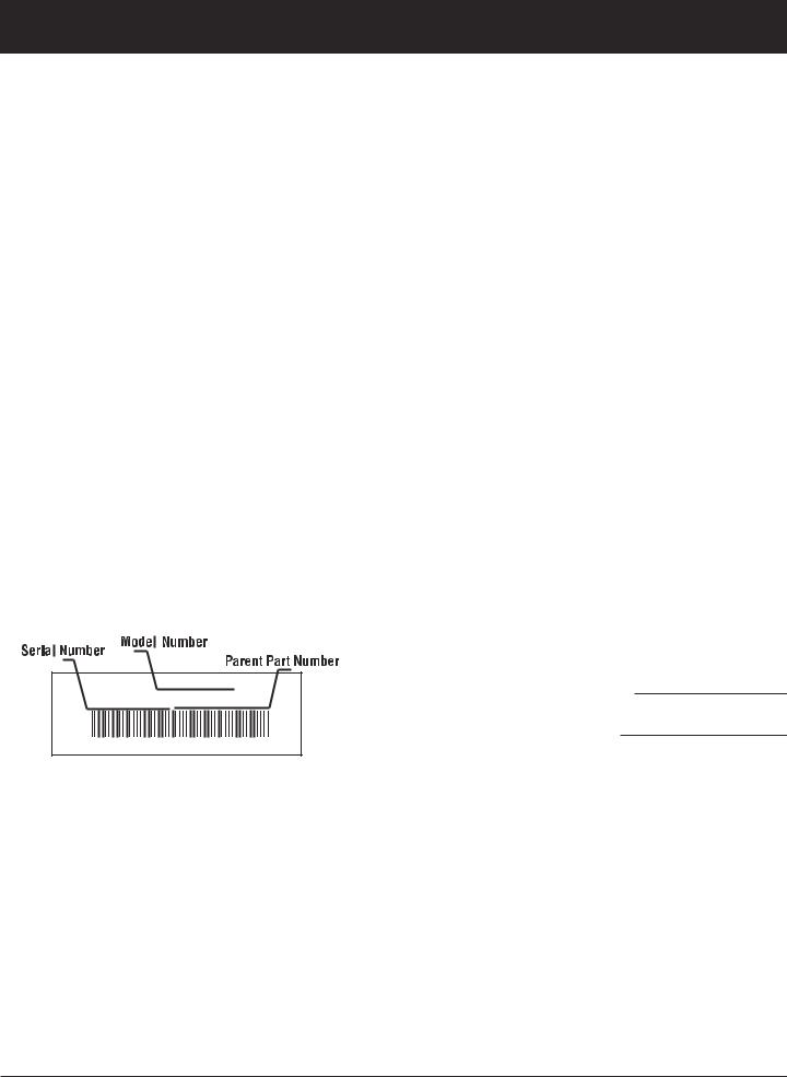
Before beginning, locate the unit’s model plate. It lists the model and serial numbers of your unit. Refer to the sample plate below and copy the information for future reference.
TABLE OF CONTENTS
Service Information . . . . . . . . . . . . . . . . . . . . . . . . .2
Rules for Safe Operation . . . . . . . . . . . . . . . . . . . . .3
Know Your Unit . . . . . . . . . . . . . . . . . . . . . . . . . . . .7
Assembly Instructions . . . . . . . . . . . . . . . . . . . . . .10
Oil and Petrol Information . . . . . . . . . . . . . . . . . . . |
15 |
Starting/Stopping Instructions . . . . . . . . . . . . . . . .16
Operating Instructions . . . . . . . . . . . . . . . . . . . . . .17
Maintenance and Repair Instructions . . . . . . . . . . .19
Troubleshooting Chart . . . . . . . . . . . . . . . . . . . . . .30
Specifications . . . . . . . . . . . . . . . . . . . . . . . . . . . . .31
|
MODEL : |
S/N : |
ITEM : |
Copy the model and parent part number here:
Copy the serial number here:
Make sure you carefully read and understand this manual before starting or operating this equipment.
THIS PRODUCT IS COVERED BY ONE OR MORE U.S. PATENTS. OTHER PATENTS PENDING.
2

RULES FOR SAFE OPERATION
The purpose of safety symbols is to attract your attention to possible dangers. The safety symbols, and their explanations, deserve your careful attention and understanding. The safety warnings do not by themselves eliminate any danger. The instructions or warnings they give are not substitutes for proper accident prevention measures.
SYMBOL MEANING
SAFETY ALERT: Indicatesdanger, warning or caution. Attention is required in order to avoid serious personal injury. May be used in conjunction with other symbols or pictographs.
NOTE: Advises you of information or instructions vital to the operation or maintenance of the equipment.
Read the Operator’s Manual(s) and follow all warnings and safety instructions.
Failure to do so can result in serious injury to the operator and/or bystanders.
SYMBOL MEANING
DANGER: Failure to obey a safety warning will
result in serious injury to yourself or to others. Always follow the safety precautions to reduce the risk of fire, electric shock and personal injury.
WARNING: Failure to obey a safety warning can
result in injury to yourself and others. Always follow the safety precautions to reduce the risk of fire, electric shock and personal injury.
CAUTION: Failure to obey a safety warning may
result in property damage or personal injury to yourself or to others. Always follow the safety precautions to reduce the risk of fire, electric shock and personal injury.
• IMPORTANT SAFETY INSTRUCTIONS •
READ ALL INSTRUCTIONS
BEFORE OPERATING
WARNING: When using the unit, you must follow the
safety rules. Please read these instructions before operating the unit in order to ensure the safety of the operator and any bystanders. Please keep these instructions for later use.
•Read the instructions carefully. Be familiar with the controls and proper use of the unit.
•Do not operate this unit when tired, ill, or under the influence of alcohol, drugs, or medication.
•Children and teens under the age of 15 must not use the unit, except for teens guided by an adult.
•All guards and safety attachments must be installed properly before operating the unit.
•Inspect the unit before use. Replace damaged parts. Check for petrol leaks. Make sure all fasteners are in place and secure. Replace parts that are cracked, chipped, or damaged in any way. Do not operate the unit with loose or damaged parts.
•Carefully inspect the area before starting the unit. Remove all debris and hard or sharp objects such as glass, wire, etc.
•Be aware of the risk of injury to the head, hands and feet.
•Clear the area of children, bystanders, and pets. At a minimum, keep all children, bystanders, and pets outside a 15 m (50 foot) radius; there still may be a risk to bystanders from thrown objects. Bystanders should be encouraged to wear eye protection. If you are approached, stop the unit immediately.
•Use only 2.41mm, 0.095 inch (for the brushcutter LT31CS), or 2.03 mm, 0.080 inch (for trimmers LT31 & LT31C), diameter original equipment manufacturer replacement line. Never use metal-
reinforced line, wire or rope. These can break off and become dangerous projectiles.
•Squeeze the throttle control and check that it returns automatically to the idle position. Make all adjustments or repairs before using unit.
•Trimmer models LT31 & LT31C only: These units was not designed to be used as a brushcutter. Do not attach or operate these units with any type of brushcutting blade or brushcutting attachment.
SAFETY WARNINGS FOR PETROL UNITS
WARNING: Petrol is highly flammable, and its
vapors can explode if ignited. Take the following precautions:
•Store petrol only in containers specifically designed and approved for the storage of such materials.
•Avoid creating a source of ignition for spilled petrol. Do not start the engine until petrol vapors dissipate.
3

RULES FOR SAFE OPERATION
•Always stop the engine and allow it to cool before filling the feul tank. Never remove the feul tank cap or add fuel when the engine is hot. Never operate the unit without the fuel cap securely in place. Loosen the fuel tank cap slowly to relieve any pressure in the tank.
•Add fuel in a clean, well-ventilated outdoor area where there are no sparks or flames. Remove the fuel cap slowly, and only after the engine stops. Do not smoke while fueling or mixing fuel. Wipe up any spilled fuel from the unit immediately.
•Avoid creating a source of ignition for spilled fuel. Do not start the engine until fuel vapors dissipate.
•Move the unit at least 9.1 m (30 feet) from the fueling source and site before starting the engine. Do not smoke. Keep sparks and open flames away from the area while adding fuel or operating the unit.
WHILE OPERATING
•Never start or run the unit inside a closed room or building. Breathing exhaust fumes can be fatal. Operate this unit only in a well-ventilated outdoor area.
•Wear safety glasses or goggles that meet ANSI Z87.1 standards and are marked as such. Wear ear/hearing protection when operating this unit. Wear a face or dust mask if the operation is dusty.
•Wear heavy long pants, boots, gloves and a long sleeve shirt. Do not wear loose clothing, jewelry, short pants, sandals or go barefoot. Secure hair above shoulder level.
•The cutting attachment shield must always be in place while operating the unit as a trimmer. Do not operate unit without both trimming lines extended, and the proper line installed. Do not extend the trimming line beyond the length of the shield.
•CLUTCH:
LT31: This unit does not have a clutch. The cutting attachment continues rotating when the engine is idling. If it does not, have the unit adjusted by an authorized service technician.
LT31C & LT31CS: These units have a clutch. The cutting attachment remains stationary when the engine is idling. If it does not, have the unit adjusted by an authorized service technician.
•Adjust the handle to your size in order to provide the best grip.
•Be sure the cutting attachment is not in contact with anything before starting the unit.
•Use the unit only in daylight or good artificial light.
•Avoid accidental starting. Be in the starting position whenever pulling the starter rope. The operator and unit must be in a stable position while starting. Refer to Starting/Stopping Instructions.
•Use the right tool. Only use this tool for its intended purpose.
•Do not overreach. Always keep proper footing and balance.
•Always hold the unit with both hands when operating. Keep a firm grip on both handles or grips.
•Keep hands, face, and feet at a distance from all moving parts. Do not touch or try to stop the cutting attachment when it rotates.
•Do not touch the engine, gear housing or muffler. These parts get extremely hot from operation, even after the unit is turned off.
•Do not operate the engine faster than the speed needed to cut, trim or edge. Do not run the engine at high speed when not cutting.
•Always stop the engine when cutting is delayed or when walking from one cutting location to another.
•If you strike or become entangled with a foreign object, stop the engine immediately and check for damage. Do not operate before repairing damage. Do not operate the unit with loose or damaged parts.
•Stop the unit, switch the engine to off, and disconnect the spark plug for maintenance or repair.
•Use only original equipment manufacturer replacement parts and accessories for this unit. These are available from your authorized service dealer. Use of any unauthorized parts or accessories could lead to serious injury to the user, or damage to the unit, and void your warranty.
•Keep unit clean of vegetation and other materials. They may become lodged between the cutting attachment and shield.
•To reduce fire hazard, replace a faulty muffler and spark arrestor. Keep the engine and muffler free from grass, leaves, excessive grease or carbon build up.
BRUSHCUTTER LT31CS ONLY: WHILE OPERATING WITH CUTTING BLADE
•Read and understand all safety warnings before operating this unit.
•Always use the shoulder harness when using the brush blade accessory.
•Keep the J-handle between the operator and cutting attachment or blade at all times.
•NEVER cut when the cutting blade is 76 cm (30 inches) or more above the ground level.
•Blade thrust may occur when the spinning blade contacts an object that it does not immediately cut. Blade thrust can be violent enough to propel the unit and/or operator in any direction, possibly causing a loss of control. Blade thrust can occur without warning if the blade snags, stalls or binds. This is more likely to occur in areas where it is difficult to see the material being cut.
•For operation with the brush blade, do not cut anything thicker than 1/2 inch or a violent kickback could occur.
4

RULES FOR SAFE OPERATION
•Do not attempt to touch or stop the blade when it is rotating.
•A coasting blade can cause injury while it continues to spin after the engine is stopped or the throttle trigger is released. Maintain proper control until the blade has completely stopped rotating.
•Do not run the unit at high speed when not cutting.
•If you strike or become entangled with a foreign object, stop the engine immediately and check for damage. Have any damage repaired before attempting further operations. Do not operate unit with a bent, cracked or dull blade. Discard blades that are bent, warped, cracked or broken.
•Do not sharpen the cutting blade. Sharpening the blade can cause the blade tip to break off while in use. This can result in severe personal injury. Replace the blade.
•Do not use the cutting blade for edging or as an edger; severe personal injury to yourself or others may incur. Use the cutting blade only for the purpose described in this manual.
•Stop the engine IMMEDIATELY if you feel excessive vibration. Vibration is a sign of trouble. Inspect thoroughly for loose nuts, bolts or damage before continuing. Repair or replace affected parts as necessary.
After Use
•Clean cutting blades with a household cleaner to remove any gum buildup. Oil the blade with machine oil to prevent rust.
•Lock up and store the cutting blade in an appropriate area to protect the blade from unauthorized use or damage.
OTHER SAFETY WARNINGS
•Never store a fueled unit inside a building where fumes may reach an open flame or spark.
•Allow the engine to cool before storing or transporting. Be sure to secure the unit while transporting.
•Store the unit in a dry area, locked up or up high to prevent unauthorized use or damage, out of the reach of children.
•Never douse or squirt the unit with water or any other liquid. Keep handles dry, clean and free from debris. Clean after each use, see Cleaning and Storage instructions.
•Keep these instructions. Refer to them often and use them to instruct other users. If you loan someone this unit, also loan them these instructions.
SAVE THESE INSTRUCTIONS
5

RULES FOR SAFE OPERATION
SAFETY AND INTERNATIONAL SYMBOLS
This operator's manual describes safety and international symbols and pictographs that may appear on this product. Read the operator's manual for complete safety, assembly, operating and maintenance and repair information.
SYMBOL MEANING |
SYMBOL MEANING |
•SAFETY ALERT SYMBOL
Indicates danger, warning, or caution. May be used in conjunction with other symbols or pictographs.
•WARNING - READ OPERATOR'S MANUAL
Read the Operator’s Manual(s) and follow all warnings and safety instructions. Failure to do so can result in serious injury to the operator and/or bystanders.
•WEAR EYE AND HEARING PROTECTION
WARNING: Thrown objects and loud noise can cause severe eye injury and hearing loss. Wear eye protection meeting ANSI Z87.1-1989 standards and ear protection when operating this unit. Use a full face shield when needed.
•WEAR HEAD PROTECTION
WARNING: Falling objects can cause severe head injury. Wear head protection when operating this unit.
•ON/OFF STOP CONTROL
ON / START / RUN
•ON/OFF STOP CONTROL
OFF or STOP
•HOT SURFACE WARNING
Do not touch a hot muffler or cylinder. You may get burned. These parts get extremely hot from operation. They remain hot for a short time even after the unit is turned off.
|
|
|
|
|
|
|
• KEEP BYSTANDERS AWAY |
|
|
|
|
|
• SHARP BLADE |
|
|
|
|
|
|
|
|
|
|
|
|
|
|
WARNING: Sharp blade on cutting |
|
|
|
|
|
|
|
|
WARNING: Keep all bystanders, |
|
|
|
|
|
|
|
|
|
|
|
|
|
|
|
|
|
|
|
|
head guard. To prevent serious |
|
|
|
|
|
|
|
|
especially children and pets, at least |
|
|
|
|
|
|
injury, do not touch line cutting blade. |
|
|
|
|
|
|
|
|
|
|
|
|
|||
|
|
|
|
|
|
|
50 feet (15 m) from the operating area. |
|
|
|
|
|
|
|
|
|
|
|
|
|
|
• PRIMER |
|
|
|
|
|
• LT31CS ONLY: Bruscutters |
|
|
|
|
|
|
|
|
Push primer bulb, fully and slowly, |
|
|
|
|
|
|
Replace dull blade |
|
|
|
|
|
|
|
|
|
|
|
|
|
Do not sharpen the cutting blade. |
|
|
|
|
|
|
|
|
10 times. |
|
|
|
|
|
|
|
|
|
|
|
|
|
|
|
|
|
|
|
|
|
Sharpening the blade can cause the |
|
|
|
|
|
|
|
|
|
|
|
|
|
|
blade tip to break off while in use. This |
|
|
|
|
|
|
|
• UNLEADED PETROL |
|
|
|
|
|
|
can result in severe personal injury. |
|
|
|
|
|
|
|
|
|
|
|
|
|
|
|
|
|
|
|
|
|
|
Always use clean, fresh unleaded |
1 |
|
2 |
|
|
3 |
• CHOKE CONTROL |
|
|
|
|
|
|
|
||||||||
|
|
|
|
|
|
|
petrol. |
|
|
|
||||
|
|
|
|
|
|
|
|
|
|
|
|
|
1. FULL choke position. |
|
|
|
|
|
|
|
|
|
|
|
|
|
|
|
|
|
|
|
|
|
|
|
|
|
|
|
|
|
|
2. PARTIAL choke position. |
|
|
|
|
|
|
|
|
|
|
|
|
|
|
|
|
|
|
|
|
|
|
|
|
|
|
|
|
|
3. RUN position. |
• OIL
Refer to operator's manual for the proper type of oil.
•THROWN OBJECTS CAN CAUSE SEVERE INJURY
WARNING: Keep clear of blower outlet. Never point the blower at yourself or others. Objects can be thrown from blower. Do not operate unit without proper attachments and guards in place.
•LT31CS ONLY: TRIMMER/ BRUSHCUTTER SAFETY
WARNING: Thrown objects and rotating cutter can cause severe injury. Keep bystanders, especially children and pets, at least 15 meters (50 ft.) away from the cutting area. The cutting head guard must be used when using the trimmer cutting head.
6
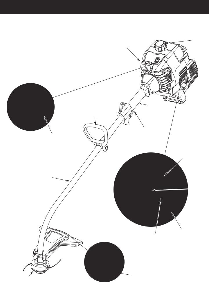
KNOW YOUR UNIT
Trimmer Model |
LT31, LT31C or LT31CS. Use this page, and the two that follow, to |
|
Take the time to identify the configuration of your unit, which is either a |
LT31 |
identify which unit is yours, then familiarize yourself with it. |
|
|
|
|
APPLICATIONS |
Starter |
Fuel Cap |
As a trimmer: |
Rope Grip |
|
•Cutting grass and light weeds
•Edging
• Decorative trimming around trees, fences, etc.
Shaft
Grip
D-Handle
Throttle
Control
On/Off Stop
Control
Blue Choke
Lever
Shaft
Tube
 Primer
Bulb
Muffler
Air Filter/Muffler
Cover
Line Cutting Blade
Cutting Attachment
7
KNOW YOUR UNIT
Trimmer Model
LT31C
APPLICATIONS
As a trimmer:
•Cutting grass and light weeds
•Edging
•Decorative trimming around trees, fences, etc.
 Fuel Cap
On/Off Stop Control
Starter Rope
Grip
Support Fitting
Shaft Grip
Throttle
Control
Blue Choke
Lever
Primer
Bulb
Muffler
Spark Plug |
Air Filter/Muffler |
|
Cover |
||
|
Line Cutting
Blade
Throttle Control
D-Handle
Shaft
Housing
Cutting
Attachment
Shield
Cutting Attachment
8
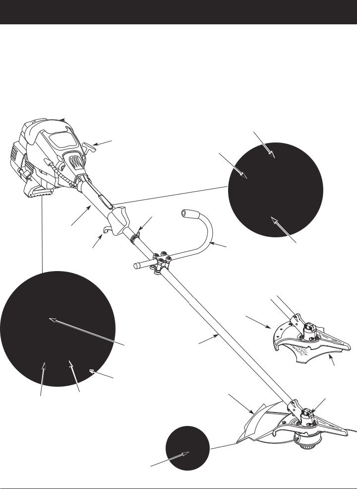
KNOW YOUR UNIT
Brushcutter
Model LT31CS
 Fuel Cap
Starter Rope
Grip
APPLICATIONS
As a trimmer:
•Cutting grass and light weeds
•Edging
•Decorative trimming around trees, fences, etc. As a brushcutter:
•Cutting weeds and light bush of up to 1/2 inch in diameter
On/Off Stop Control
Throttle Lock-Out
Support Fitting
Shaft Grip
J-Handle |
Throttle Control |
Throttle
Control

 Blue Choke
Lever Blade Shield /
Shield Mount
|
Primer Bulb |
Shaft |
|
|
|
Housing |
|
|
|
|
Cutting Blade |
|
Muffler |
Cutting |
|
|
|
Attachment |
Gear Housing |
Spark Plug |
Air Filter/Muffler |
Shield |
|
|
|
||
Cover |
|
|
|
|
|
|
Cutting Attachment
Line Cutting
Blade
9
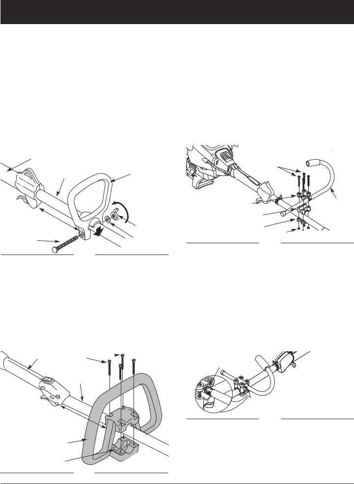
ASSEMBLY INSTRUCTIONS
INSTALL AND ADJUST THE HANDLE
Use the following information to install or adjust the handle onto your trimmer. Follow the instructions that apply to your type of handle.
LT31: Small D-handle
1.Push the D-handle down onto the shaft housing so that the handle slants towards the shaft grip (Fig. 1). The squared bolt hole in the handle is to the right.
2.Insert the shoulder bolt into the squared hole in the handle and push through. On the left side of the handle, place the washer on the bolt, then screw the wing nut onto the bolt. Do not tighten until you make the handle adjustment.
3.Rotate the D-handle to place the grip above the top of the shaft housing. Place it a minimum of 15.24 cm (6 inches) from the end of the shaft grip.
Shaft Grip
Shaft Housing |
D-Handle |
3.Start screws with a large Flat-head or T-25 Torx screwdriver. Do not tighten until you make the handle adjustment.
4.If the D-handle was pre-installed, loosen the screws on the handle just enough to move it.
5.While holding the unit in the operating position
(Fig. 27), maneuver the D-handle to the location that provides you the best grip.
6.Tighten the clamp screws evenly, until the D-handle is secure.
LT31CS: J-handle
1.Place the J-handle between the top and middle clamp pieces (Fig. 3).
(4) Screws |
|
Tighten |
Minimum 6 inches |
Wing Nut |
(15.24 cm) |
|
Bolt |
Washer |
|
Fig. 1
4.While holding the unit in the operating position (Fig. 27), position the D-handle to the location that provides you the best grip.
5.Tighten the wing nut until the D-handle is secure.
LT31C: Large D-handle
1.Remove the screws and bottom clamp piece that were installed on the D-handle for shipping.
2.Place D-handle the over the shaft housing and onto the bottom clamp (Fig. 2). Place it a minimum of 15.24 cm (6 inches) from the end of the shaft grip.
Shaft Grip
(4) Screws
Shaft
Housing
Minimum 6 inches (15.24 cm)
D-Handle
Bottom Clamp
Fig. 2
Top Clamp |
J-Handle |
Middle Clamp |
|
Bottom Clamp |
Nuts |
|
|
|
Fig. 3 |
2.While holding the three pieces together, install the four
(4) screws through the top clamp and into middle clamp.
NOTE: The holes in the top and middle clamp will line up only when assembled correctly.
3.Place the clamps and the J-handle over the shaft housing and onto the bottom clamp.
4.Hold each hex nut in the bottom clamp recess with a finger. Start screws with a large Phillips screwdriver. Do not tighten until you make the handle adjustment.
5.Slide the J-handle in or out until the arrow/white line on the decal touches the clamp assembly (Fig. 4). You must first loosen the screws if the handle is pre-installed.
Decal
Fig. 4
6.While holding the unit in the operating position (Fig. 27), position the J-handle to the location that provides you the best grip.
7.Tighten the clamp screws evenly, until the J-handle is secure.
10
 Loading...