


OPERATOR’S MANUAL
MODELS 615 E645E E665E
IMPORTANT: READ SAFETY RULES AND INSTRUCTIONS CAREFULLY
Warning: This unit is equipped with an internal combustion engine and should not be used on or near any unimproved forestcovered, brush-covered or grass-covered land unless the engine’s exhaust system is equipped with a spark arrester meeting applicable local or state laws (if any). If a spark arrester is used, it should be maintained in effective working order by the operator.
In the State of California the above is required by law (Section 4442 of the California Public Resources Code). Other states may have similar laws. Federal laws apply on federal lands. A spark arrester for the muffler is available through your nearest engine authorized service dealer or contact the service department, P.O. Box 368022 Cleveland, Ohio 44136-9722.
MTD PRODUCTS INC. P.O. BOX 368022 CLEVELAND, OHIO 44136-9722
PRINTED IN U.S.A. |
FORM NO. 770-0830A |

SECTION 1: IMPORTANT SAFE OPERATION PRACTICES
WARNING: THIS SYMBOL POINTS OUT IMPORTANT SAFETY INSTRUCTIONS WHICH, IF NOT FOLLOWED, COULD ENDANGER THE PERSONAL SAFETY AND/OR PROPERTY OF YOURSELF AND OTHERS. READ AND FOLLOW ALL INSTRUCTIONS IN THIS MANUAL BEFORE ATTEMPTING TO OPERATE YOUR SNOW THROWER. FAILURE TO COMPLY WITH THESE INSTRUCTIONS MAY RESULT IN PERSONAL INJURY. WHEN YOU SEE THIS SYMBOLHEED ITS WARNING.
WARNING: The Engine Exhaust from this product contains chemicals known to the State of California to cause cancer, birth defects or other reproductive harm.
DANGER: Your snow thrower was built to be operated according to the rules for safe operation in this manual. As with any type of power equipment, carelessness or error on the part of the operator can result in serious injury. If you violate any of these rules, you may cause serious injury to yourself or others.
1. TRAINING
•Read this operator's manual carefully in its entirety before attempting to assemble or operate this machine. Be completely familiar with the controls and the proper use of this machine before operating it. Keep this manual in a safe place for future and regular reference and for ordering replacement parts.
•Never allow children under 14 years old to operate a snow thrower. Children 14 years old and over should only operate snow thrower under close parental supervision. Only persons well acquainted with these rules of safe operation should be allowed to use your snow thrower.
•No one should operate this unit while intoxicated or while taking medication that impairs the senses or reactions.
•Keep the area of operation clear of all persons, especially small children and pets.
•Exercise caution to avoid slipping or falling, especially when operating in reverse.
2.PREPARATION
•Thoroughly inspect the area where the equipment is to be used and remove all door mats, sleds, boards, wires and other foreign objects.
•Disengage all clutches and shift into neutral before starting engine.
•Do not operate equipment without wearing adequate winter outer garments. Do not wear jewelry, long scarfs or other loose clothing which could become entangled in moving parts. Wear footwear which will improve footing on slippery surfaces.
•Before working with gasoline, extinguish all cigarettes and other sources of ignition. Check the fuel before starting the engine. Gasoline is an extremely flammable fuel. Do not fill the gasoline tank indoors, while the engine is running, or until engine has been allowed to cool at least two minutes. Replace gasoline cap securely and wipe off any spilled gasoline before starting the engine as it may cause a fire or explosion.
•Use a grounded three wire plug-in for all units with electric drive motors or electric starting motors.
•Adjust collector housing height to clear gravel or crushed rock surface.
•Never attempt to make any adjustments while engine is running (except where specifically recommended by manufacturer).
•Let engine and machine adjust to outdoor temperature before starting to clear snow.
•Always wear safety glasses or eye shields during operation or while performing an adjustment or repair, to protect eyes from foreign objects that may be thrown from the machine in any direction.
3.OPERATION
•Do not put hands or feet near or under rotating parts. Keep clear of discharge opening and auger at all times.
•Exercise extreme caution when operating on or crossing gravel drives, walks, or roads. Stay alert for hidden hazards or traffic. Do not carry passengers.
•After striking a foreign object, stop the engine, remove wire from spark plug, and thoroughly inspect the snow thrower for any damage. Repair the damage before restarting and operating the snow thrower.
2
•If the snow thrower should start to vibrate abnormally, stop the engine and check immediately for the cause. Vibration is generally a warning of trouble.
•Stop engine whenever you leave the operating position, before unclogging the collector/impeller housing or discharge guide, and making any repairs, adjustments, or inspections. Never place your hand in the discharge or collector openings. Use a stick or wooden broom handle to unclog the discharge opening.
•Take all possible precautions when leaving the unit unattended. Disengage the collector/impeller, shift into neutral, stop the engine, and remove the key.
•When cleaning, repairing, or inspecting, make certain collector/impeller and all moving parts have stopped. Disconnect spark plug wire and keep away from plug to prevent accidental starting.
•Do not run engine indoors, except when starting engine and transporting snow thrower in or out of building. Open doors. Exhaust fumes are dangerous.
•Do not clear snow across the face of slopes. Exercise extreme caution when changing direction on slopes. Do not attempt to clear steep slopes.
•Never operate snow thrower without guards, plates, or other safety protection devices in place.
•Never operate snow thrower near glass enclosure, automobiles, window wells, drop off, etc., without proper adjustments of snow thrower discharge angle. Keep children and pets away.
•Do not overload machine capacity by attempting to clear snow at too fast a rate.
•Never operate the machine at high transport speeds on slippery surfaces. Look behind and use care when backing.
•Never direct discharge at bystanders or allow anyone in front of unit.
•Disengage power to collector/impeller when transporting or not in use.
•Use only attachments and accessories approved by the manufacturer of snow thrower (such as wheel weights, counter weights, cabs, etc.).
•Never operate the snow thrower without good visibility or light. Always be sure of your footing and keep a firm hold on the handles. Walk, never run.
•Muffler and engine become hot and can cause a burn. Do not touch.
4.MAINTENANCE AND STORAGE
•Check shear bolts, engine mounting bolts, etc., at frequent intervals for proper tightness to be sure equipment is in safe working condition.
•Never store the machine with fuel in the fuel tank inside a building where ignition sources are present, such as hot water and space heaters, clothes dryers, and the like. Allow engine to cool before storing in any enclosure.
•Always refer to operator's manual instructions for important details if snow thrower is to be stored for an extended period.
•Run machine a few minutes after throwing snow to prevent freeze up of collector/impeller.
•Check clutch controls periodically to verify they engage and disengage properly and readjust if necessary. Refer to operator's manual for adjustment instructions.
WARNING - YOUR RESPONSIBILITY: Restrict the use of this power machine to persons who read, understand and follow the warnings and instructions in this manual and on the machine.
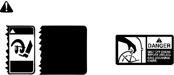
 DANGER
AVOID INJURY FROM ROTATING AUGER - KEEP HANDS, FEET ANDCLOTHINGAWAY.
 WARNING
1.STOP ENGINE BEFORE REMOVING DEBRIS AND SERVICING UNIT
2.KEEP CLEAR OF IMPELLER WHILE ENGINE IS RUNNING
3.NEVER DIRECT DISCHARGE AT BYSTANDERS OR WINDOWS OR ALLOW ANYONE IN FRONT OF UNIT
4.THOROUGHLY INSPECT THE AREA WHERE THE EQUIPMENT IS TO BE USED AND REMOVE ALL DOOR MATS, SLEDS, BOARDS, WIRES AND OTHER FOREIGN OBJECTS
5.REFER TO OWNERS MANUAL FOR FULL INSTRUCTIONS
3396MW
Safety Labels Found on Snow Thrower
3

SECTION 2: FINDING YOUR MODEL NUMBER
This Operators Manual is an important part of your new snow thrower. It will help you assemble, prepare and maintain your snow thrower. Please read and understand what it says.
Before you start to prepare your snow thrower for its first use, please locate the model plate and copy the information from it in this Operators Manual. The information on the model plate is very important if you need help from your dealer or the MTD customer support department.
•Every snow thrower has a model plate. You can locate it by standing behind the unit in the operating position and looking down at the dash panel.
•The model plate will look like this.
|
|
|
|
|
|
This is where your model number will be. |
||||
|
|
|
|
|
|
|||||
|
|
|
|
|
|
|
|
|
|
|
|
XXX-X-XXX-X-XXX XXXXXXXXXXX |
|
|
|
|
|
|
|||
|
|
|
|
|
|
This is where your serial number will be. |
||||
|
|
|
|
|
|
|||||
|
|
|
|
|
Copy the model number here: |
|||||
|
|
MTD PRODUCTS INC |
Copy the serial number here: |
|
|
|
|
|||
|
|
CLEVELAND, OHIO 44136 |
|
|
||||||
|
|
|
||||||||
|
|
|
|
|
|
|
|
|
|
|
SECTION 3: CALLING CUSTOMER SUPPORT
If you are having difficulty assembling this product or if you have any question regarding the controls, operation or maintenance of this snow thrower, please call the Customer Support Department. You can reach them by calling:
1-800-800-7310
Before you call, make sure that you have both your model and serial number ready. By having the model and serial number ready, you help the Customer Support Representative give you faster service. To find your units model and serial number, see SECTION 2: FINDING YOUR MODEL NUMBER.
4

SECTION 4: CONTENTS OF HARDWARE PACK
Lay out the hardware according to the illustration for identification purposes. Part numbers are shown in parentheses. (Hardware pack may contain extra items which are not used on your unit.)
A |
ATTACHING THE HANDLES |
(4)Lock Washers (C) |
(2)Hex Bolts (A) |
(736-0119) |
|
|
|
|
|
(710-3180) |
|
(2) Hex Bolts (B) |
(2) Saddle (I) |
|
710-3008 |
||
(784-5599) |
||
|
C ATTACHING THE SPEED SELECTOR PLATE AND SHIFT LEVER
(4) Self-Tapping
Screws (F)
(710-0599)
(2) Hex
Bolts (G)
(712-3015) (2) Hex Lock Nuts (H)
(712-3027)
F ATTACHING THE CHUTE CRANK ASSEMBLY
(2) Hex Nuts (D)
(712-3010)
Cupped Washer (N)
(736-0242)
Hair Pin Clip
(2) Flat Washers (714-0104)
(736-0185)
Hex lock nuts cannot be threaded onto a bolt by hand. A wrench is required for assembly. This type of nut is used where vibration occurs.
B ATTACHING THE HANDLE PANEL
(4) Carriage Bolts (E)
(710-0262)
(4) Lock
Washers (C)
(4) Hex Nuts (D) (736-0119)
(712-3010)
D ATTACHING THE CLUTCH CABLES
(2)“Z” Fitting (R) (746-0778)
(2) Hex Nuts (J)
(712-0121)
E ATTACHING THE CHUTE ASSEMBLY
|
(6) Hex Lock Nuts (M) |
|
|
(712-3027) |
|
(6) Hex Bolts (K) |
(3) Chute Flange Keepers |
|
(710-3015) |
||
(Not Shown) (731-0851) |
||
|
AUGER SHEAR BOLTS (SPARES)
G (2) Shear Bolts (710-0890A)
(2)Hex Lock Nuts (712-0429)
5
SECTION 5: ASSEMBLY INSTRUCTIONS
IMPORTANT: After assembly, service engine with gasoline, and check oil level as instructed in the separate engine manual packed with your unit.
NOTE: References to right or left side of the snow thrower are determined from behind the unit in the operating position.
UNPACKING
•Remove staples or break glue on the top flaps of the carton. Remove any loose parts included with unit (i.e., operator’s manual, etc.).
•Cut along dotted lines and lay end of carton down flat. Remove packing material.
•Roll unit out of carton. Check carton thoroughly for loose parts before discarding.
TOOLS REQUIRED FOR ASSEMBLY
•(1) 3/8" or adjustable wrench
•(2) 7/16" or adjustable wrench
•(2) 1/2" or adjustable wrench
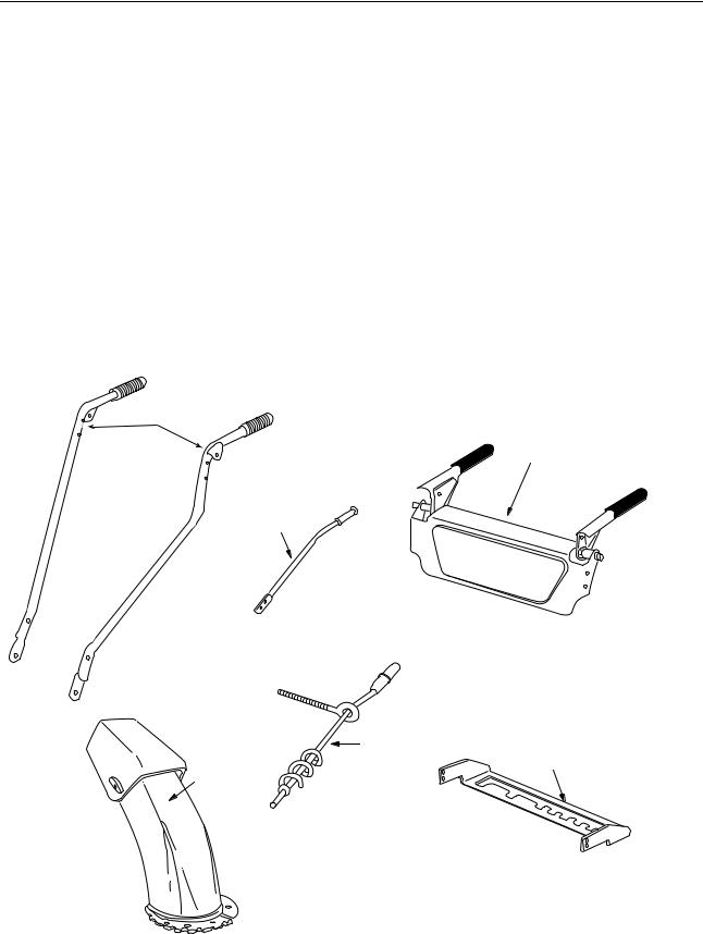
LOOSE PARTS IN CARTON (See Figure 1)
A(2) Handles (Right and Left)
B(1) Handle Panel Assembly
C(1) Speed Selector Plate
D(1) Shift Lever
E(1) Chute Crank Assembly
F(1) Chute Assembly
(1)Hardware Pack
A
B
D
E
C
F
Figure 1
6
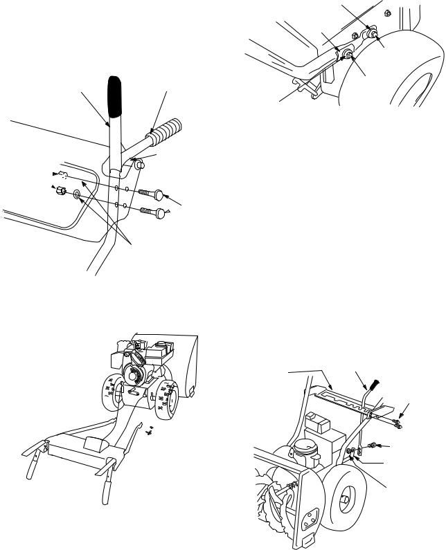
ASSEMBLING THE HANDLES AND
HANDLE PANEL (Hardware B)
1.Raise both clutch grips.
2.Lower left and right handles down through handle panel between the pivot rod and the clutch grips and attach using hardware B. See Figure 2.
Clutch Grip |
Left Handle |
Pivot Rod
Hex
Nuts(D)


Carriage
 Bolts (E)
Lock Washers (C)
Figure 2
3.Do not tighten at this time.
4.Lay handle panel assembly behind snow thrower. See Figure 3.
Figure 3
5.Insert hex bolts and lock washers through bottom holes in handles and bottom holes in snow thrower. Do not tighten.
6.Raise handles up until upper holes in handles and upper holes in snow thrower frame line up.
7.Attach with hex bolts lock washers and saddles. See Figure 4.
7
Lock Washer (C)
Saddle (I)
Hex Bolt (B)
Hex Bolt (A)
Lock Washer (C)
Figure 4
ATTACHING SPEED SELECTOR PLATE
AND SHIFT LEVER (Hardware C)
1.Assemble the speed selector plate to the outside of the handles as shown in Figure 5. The speed selector plate should not be assembled between the handles and the engine. Secure using four self-tapping screws (F).
2.Insert the shift lever through slot in the speed selector plate.
NOTE: The bend in the lever should be towards the operator. Secure shift lever to the shift lever spring using two hex bolts (G) and hex lock nuts (H). Tighten both bolts finger tight. At this point the shift lever and shift lever spring are not against each other. As you tighten the bolts and nuts with two 7/ 16" wrenches they will pull together. See Figure 5.
Speed |
Shift Lever |
Selector |
Self-Tapping |
Plate |
|
|
Screw (F) |
|
Hex |
|
Bolts (G) |
|
Shift Lever |
|
Spring |
|
Hex Lock |
|
Nuts (H) |
Figure 5
3.Tighten all hardware assembled to this point. CLUTCH GRIPS MUST MOVE FREELY.
ATTACHING THE CLUTCH CABLES
(Hardware D)
1.Thread hex nuts (J) onto the “Z” fittings (R) (see inset,). Insert “Z” fitting into hole in clutch grips. See Figure 6.
“Z” Fitting
(R)
Hex
Nut
(J)
Figure 6
2.Route the left cable between engine and speed selector plate and then between handle panel and clutch lever pivot rod before threading onto the left “Z” fitting. Assemble the right cable using the same route.
3.Correct adjustment on cables is minimal slack but not tight. Tighten hex nuts when adjustment is correct.
NOTE: If the right hand lockout cable is not adjusted correctly, the wheels will tend to turn. If the left hand lockout cable is not adjusted correctly, the augers will not stop rotating.
WARNING: There must not be any tension on either clutch cable with the drive or auger clutch grip in the disengaged (up) position. These clutches are a safety feature, and their function can be overridden if there is tension on either cable with the clutches disengaged.
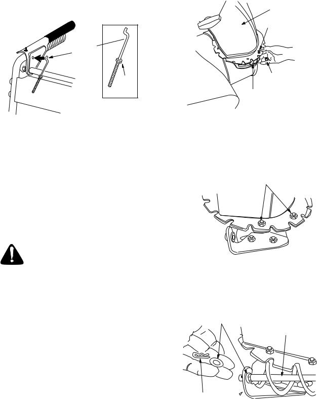
ATTACHING THE CHUTE ASSEMBLY
(Hardware E)
Note: Lock nuts cannot be threaded onto a bolt by hand. Tighten with 2 7/16” wrenches. This type of nut is used where vibration occurs.
Chute
Assembly
Hex Bolt
Hex Lock Nut
Chute Flange
Keeper
Figure 7
ATTACHING THE CHUTE CRANK
(Hardware F)
1.Loosen the two hex nuts which secure the chute crank support bracket (see Figure 8) to the snow thrower housing.
Carriage Bolts
Hex Lock Nuts
Lower
Chute
Crank
Bracket
Figure 8
2.Place one flat washer over the end of the chute crank, then insert the end of the crank into the hole in the plastic bushing in the chute bracket. See Figure 9. Place second flat washer on chute crank, and secure with hairpin clip.
Flat
Washer Chute
Crank
1.Place chute assembly over chute opening, with the opening in the chute assembly facing the front of the unit. Place chute flange keepers beneath lip of chute assembly, with the flat side of chute flange keeper facing downward.
2.Insert hex bolt (K) up through chute flange keeper and chute assembly as shown in Figure 7. Secure with hex lock nut (M). After assembling all three chute flange keepers, tighten all nuts and bolts securely. Do not overtighten.
8
Hairpin Clip
Chute Crank
Bracket
Figure 9
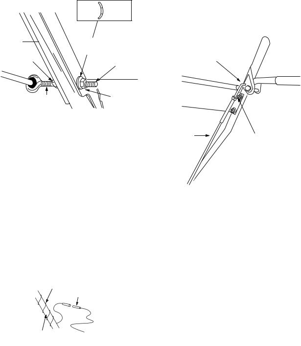
3.Thread one hex nut (D) onto the eyebolt on the chute crank assembly until there is at least two inches of threads showing between the nut and the head of the eyebolt. See Figure 10.
Cup Crown
Side Side
Left
Handle  Cupped
Washer (N)
Hex Nut |
Eyebolt |
(D) |
2” of |
Hex Nut |
Threads |
(D) |
Figure 10
4.Place the eyebolt into the hole located half way up the left handle. Secure with cupped washer
(N)(cupped side against the handle, see inset, Figure 10) and hex nut (D).
5.Adjust the chute crank support bracket (see Figure 9) so that the spiral on the chute crank fully engages the teeth on the chute assembly. Tighten the nuts on the chute crank bracket securely. Tighten the hex nuts on the eyebolt.
6.Check to make sure all nuts and bolts on the control panel and all four bolts which secure the handles to the frame are tight.
LAMP WIRING (Models E645 and E665 only) Wrap the wire from the lamp down the right handle until the wire can be plugged into the alternator lead wire under the fuel tank. Be sure the lamp wire does not interfere with the movement of any controls or cables.
Lamp Wire Alternator
Lead
Right Handle
Figure 11
FINAL ASSEMBLY AND ADJUSTMENTS
Auger Drive Clutch
To check the adjustment of the auger drive clutch, push forward on the left hand clutch grip (depress the rubber bumper). There should be slack in the cable.
9
Release the clutch grip. The cable should be straight. Make certain you can depress the auger drive clutch grip against the left handle completely.
If necessary, loosen the hex lock nut and thread the cable in (for less slack) or out (for more slack) as necessary. Refer to Figure 12. Recheck the adjustment.
Tighten the lock nut against the cable when correct adjustment is reached.
“Z” Fitting
Cable |
Hex Bolt |
|
Figure 12
Traction Drive Clutch and Shift Lever
Adjustment
To check the adjustment of the traction drive clutch and shift lever, move the shift lever all the way over to fifth (5) position. With the traction drive lever released, push the snow thrower forward. The unit should move forward freely. Then engage the traction drive clutch grip. The wheels should stop turning.
Now release the traction drive clutch grip, and push the unit again. Move the shift lever back to the fast reverse position, then all the way over again. There should be no resistance in the shift lever, and the and the wheels should keep turning
If you have resistance when moving the shift lever or the wheels stop when they should not, loosen the jam nut on the traction drive cable and unthread the cable one turn. If the wheels do not stop when you engage the traction drive clutch grip, loosen the jam nut on the traction drive cable and thread the cable in one turn. Recheck the adjustment and repeat as necessary. Tighten the jam nut to secure the cable when correct adjustment is reached.
NOTE: If you are uncertain that you have reached the correct adjustment, refer to the Adjustment section.
 Loading...