


Safety • Assembly • Operation • Tips & Techniques • Maintenance • Troubleshooting • Parts Lists • Warranty
OPERATOR’S MANUAL
Model OEM-190-032 190-032-101
42-inch Two-Stage Snow Thrower Attachment
For FastAttach™ Compatible Lawn Tractors & Garden Tractors
|
|
FORM NO. 769-01933E |
PRINTED IN U.S.A. |
MTD LLC, P.O. BOX 361131 CLEVELAND, OHIO 44136-0019 |
4/24/07 |
This Operator’s Manual is an important part of your snow thrower attachment. It will help you assemble, prepare and maintain the unit for best performance. Please read and understand what it says.
TABLE OF CONTENTS
1. Rider Model Identification................................. |
Page 3 |
9. Controls............................................................ |
Page 20 |
||
2. |
Snow Thrower Attachment Safety.................... |
Page 4-5 |
10.Operation......................................................... |
Page 21 |
|
3. |
Carton Contents............................................... |
Page 6-7 |
11. Adjustments.................................................... |
Page 22 |
|
4. Assembly Models 600-649 & 800 Series......... |
Page 8-13 |
12. |
Maintenance................................................... |
Page 23 |
|
5. |
Assembly All Model 700 Series........................ |
Page 14-15 |
13. |
Parts List........................................................ |
Page 24-29 |
6. |
Attaching Controls............................................ |
Page 16 |
13. |
Notes.............................................................. |
Page 30-31 |
7. |
Attaching Auger Housing................................. |
Page 17 |
Warranty........................................................... |
Page 32 |
|
8. |
Routing Upper & Lower Drive Belts.................. |
Page 18-19 |
|
|
|
|
|
|
|
|
|
|
|
|
|
|
|
Finding and Recording Model Number
BEFORE YOU START ASSEMBLING YOUR NEW EQUIPMENT,
please locate the model plate and copy the information from it in this Operator’s Manual for future reference. The information on the model plate is very important if you need help from our Customer Support Department or your authorized dealer. You can locate it by looking on the top rear portion of the auger housing:
Model Number |
Serial Number |
*Locate the model plate on your snow thrower attachment and copy the information from it in the space provided above for future reference.
Customer Support
Please do NOT return the unit to the retailer from which it was purchased, without first contacting Customer Support.
If you have difficulty assembling this product or have any questions regarding the controls, operation, or maintenance of this unit, you can seek help from the experts. Choose from the options below:
•Visit www.mtdproducts.com. Click on the Service & Support menu option.
•Phone a Customer Support Representative at 1-800-800-7310.
•Please have your unit’s model number and serial number ready when you call. See above to locate this information. You will be asked to enter the serial number in order to process your call.
Model Plate
1 |
30 |
3 |
81 |
11 |
63 |
6 |
47 |
C3 |
-00- |
LLX |
20 |
OB |
28 |
DT. |
-00- |
O. |
30 |
MP |
38 |
Figure 1
Sample Model Number
1 3 A M 7 9 0 G 0 0 0
Indicates Model Series 700
Figure 2
Snow Thrower
Attachment
NOTE: This Operator’s Manual covers several models. Snow thrower hook-up instructions vary by model. Not all features discussed in this manual are applicable to all snow thrower attachments. Assistance may be needed to complete instalation.
To The Owner
Model OEM-190-032 two-stage snow thrower attachment is designed for use on FastAttach™ Compatible Lawn Tractors and Garden Tractors ONLY. It will NOT fit nor operate properly or safely on ANY other tractor.
Determine The Model
of Your Rider
Since this manual is designed for installation of your new snow thrower attachment on several different rider units, it is important for you to determine which model of rider you have. Therefore you will know which set of instructions in the following pages to follow.
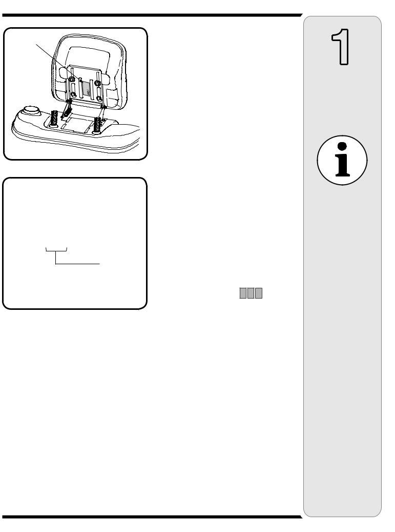
To determine which model of rider you have, you will need to locate the rider’s model plate, located under the seat. Simply flip the seat up and locate the model plate, which will consist of an 11 digit/letter model number and a serial number. For ease in this installation and for future use, copy your rider’s model number & serial number below now:
Rider Model Number:__ __ __ __ __ __ __ __ __ __ __
Rider Serial Number:_________________________
The 5th, 6th & 7th numbers from the left in your model number determine your rider’s model series. See Figure 2.
When you fill in your model number in the space above, the actual model series number should fall into the gray shaded area.
Now that you have determined what model rider you are attaching this snow thrower attachment to, follow the instructions in the following pages according to your
model of rider. You can locate which instructions apply to your model of rider by the gray-shaded area in the border of each page. For instance, an 809 or 80R would signify that you should follow the instructions for Model Series 800.
1
Rider Model Identification
NOTE:
References to LEFT and RIGHT indicate the left and right sides of the tractor when facing forward in the operator’s position. Reference to the FRONT indicates the grille end; to the REAR, the rear end of the rider.

3
Carton
Contents
If you are missing any parts, please do not contact the retailer where you purchased this unit, call MTD directly at 1-330-220-4MTD or
toll free at 1-800-800-7310.
Undercarriage Assembly |
Self-Adhesive |
|
|
|
Reflectors |
Cable Ties
Extension Spring
Upper Chute Crank Rod
Extension Spring
Cotter Pin
Lift Handle |
Click Pins & |
|
Clevis Pins |
||
Assembly |
||
|
Auger Housing |
Spare Shear Bolts |
Assembly w/ |
& Hex Lock Nuts |
Linkage |
|
|
Figure 3 |

CONTENTS OF CARTON
Before beginning installation, remove all parts from the carton to make sure everything is present. Carton contents are listed below and shown in Figure 3. Hardware part numbers are shown in parentheses.
•One Auger Housing Assembly w/ Lower V-belt
•One Undercarriage Assembly w/ Upper V-belt
•One Lift Handle Assembly
•One Upper Chute Crank Rod
•Three Cable Ties (725-0157)
•Two Spare Shear Pins (738-04124) & Cotter Pins (714-04040)
•One Cotter Pin (714-0507)
•Two Self-adhesive Reflectors (730-3000)
•Extension Spring (732-04237)
•Extension Spring (732-04237)
•Clevis Pin (711-0332)
•Click Pin (714-0145)
3
Carton
Contents
If you are missing any parts, please do not contact the retailer where you purchased this unit, call MTD directly at 1-330-220-4MTD or
toll free at 1-800-800-7310.
4
Assembly
Model Series 600-649 & All 800 series.
WARNING
Before installing attachment, place tractor on a firm and level surface. Place the PTO in
the disengaged (OFF) position, set the parking brake, shut engine off and remove key to prevent unintended starting.
WARNING: Before installing attachment, place tractor on a firm and level surface. Place the PTO in the disengaged (OFF) position, set the parking brake, shut engine off and remove key to prevent unintended starting.
NOTE: References to LEFT and RIGHT indicate the left and right sides of the tractor when facing forward in the operator’s position. Reference to the FRONT indicates the grille end; to the REAR the drawbar end.
IMPORTANT: You must first figure out which model of rider you are attaching this snow thrower to. Refer to Determine Your Model of Rider on page 3 of this manual to determine what model rider you are attempting to install this attachment to. Then proceed to the applicable instructions for your model of rider.
Your tractor’s cutting deck, PTO belt and front deck stabilizer bracket must be removed prior to mounting the snow thrower attachment. Refer to your tractor’s Operator’s Manual for detailed instructions. If your tractor is equipped with any front-end accessory (i.e. front bumper kit), it must also be removed.
Do you have an Electric PTO or Manual PTO?
If you engage your tractor’s cutting deck by using your left hand to pivot a lever forward, your tractor has a Manual PTO. If you engage your tractor’s cutting deck by pulling outward on a small knob located on the tractor’s dash, your tractor has an Electric PTO.
Mounting the Idler Assembly
Electric PTO Undercarriage
Assembly Setup
Proceed as follows when mounting this snow thrower attachment to a tractor equipped with a 42, 46, 50 or 54-inch deck with electric PTO:
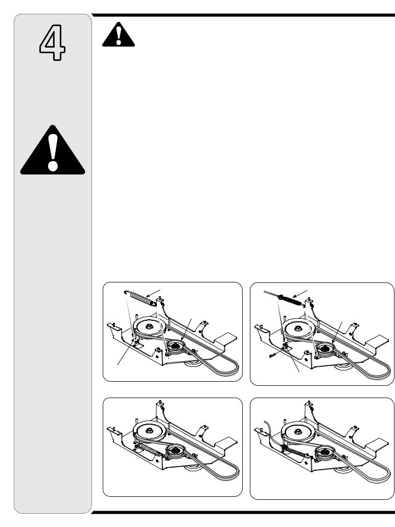
1.Attach one end of the extension spring (732-0594A) to the hole in the idler assembly. Mount the opposite end of the extension spring to the belt keeper pin as illustrated in Figure 4–1.
2.Refer to Figure 4–2 for correct position.
Extension Spring
Idler Pulley &
Idler Bracket
Belt Keeper Pin
Figure 4–1
Manual PTO Undercarriage
Assembly Setup
1.Attach the PTO cable to the idler bracket, then fit the cable into the slotted fitting as seen in Figure 4–3.
NOTE: The PTO cable should be hanging down under you tractor after you removed the mowing deck. You will need to slide the undercarriage unit under your tractor in position for which it will be mounted. The slanted side should be pointed towards the front of your tractor.
2. Refer to Figure 4–4 for correct position.
PTO Cable
Idler Pulley &
Idler Bracket
Slotted Fitting
Figure 4–3
Figure 4–2 |
Figure 4–4 |
|
 Loading...