


MPG X570
Table of contents
 Loading...
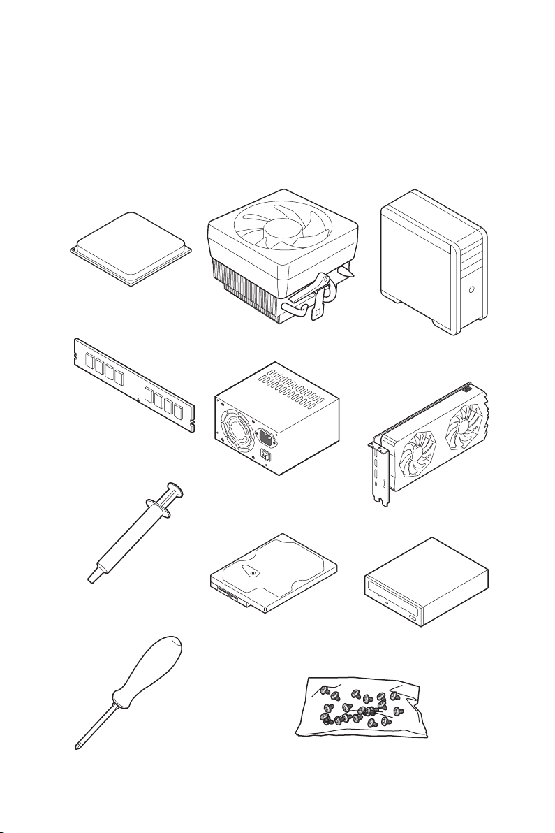
1
Quick Start
Quick Start
Thank you for purchasing the MSI
®
MPG X570 GAMING PRO CARBON WIFI
motherboard. This Quick Start section provides demonstration diagrams about how
to install your computer. Some of the installations also provide video demonstrations.
Please link to the URL to watch it with the web browser on your phone or tablet. You
may have even link to the URL by scanning the QR code.
Preparing Tools and Components
DDR4 Memory
Graphics Card
SATA Hard Disk Drive
SATA DVD Drive
Phillips Screwdriver
Chassis
Power Supply Unit
A Package of Screws
Thermal Paste
CPU Fan
AMD
®
AM4 CPU

2
Quick Start
Safety Information
y The components included in this package are prone to damage from electrostatic
discharge (ESD). Please adhere to the following instructions to ensure successful
computer assembly.
y Ensure that all components are securely connected. Loose connections may cause
the computer to not recognize a component or fail to start.
y Hold the motherboard by the edges to avoid touching sensitive components.
y It is recommended to wear an electrostatic discharge (ESD) wrist strap when
handling the motherboard to prevent electrostatic damage. If an ESD wrist strap is
not available, discharge yourself of static electricity by touching another metal object
before handling the motherboard.
y Store the motherboard in an electrostatic shielding container or on an anti-static pad
whenever the motherboard is not installed.
y Before turning on the computer, ensure that there are no loose screws or metal
components on the motherboard or anywhere within the computer case.
y Do not boot the computer before installation is completed. This could cause
permanent damage to the components as well as injury to the user.
y If you need help during any installation step, please consult a certified computer
technician.
y Always turn off the power supply and unplug the power cord from the power outlet
before installing or removing any computer component.
y Keep this user guide for future reference.
y Keep this motherboard away from humidity.
y Make sure that your electrical outlet provides the same voltage as is indicated on the
PSU, before connecting the PSU to the electrical outlet.
y Place the power cord such a way that people can not step on it. Do not place anything
over the power cord.
y All cautions and warnings on the motherboard should be noted.
y If any of the following situations arises, get the motherboard checked by service
personnel:
Liquid has penetrated into the computer.
The motherboard has been exposed to moisture.
The motherboard does not work well or you can not get it work according to user
guide.
The motherboard has been dropped and damaged.
The motherboard has obvious sign of breakage.
y Do not leave this motherboard in an environment above 60°C (140°F), it may damage
the motherboard.
3
Quick Start
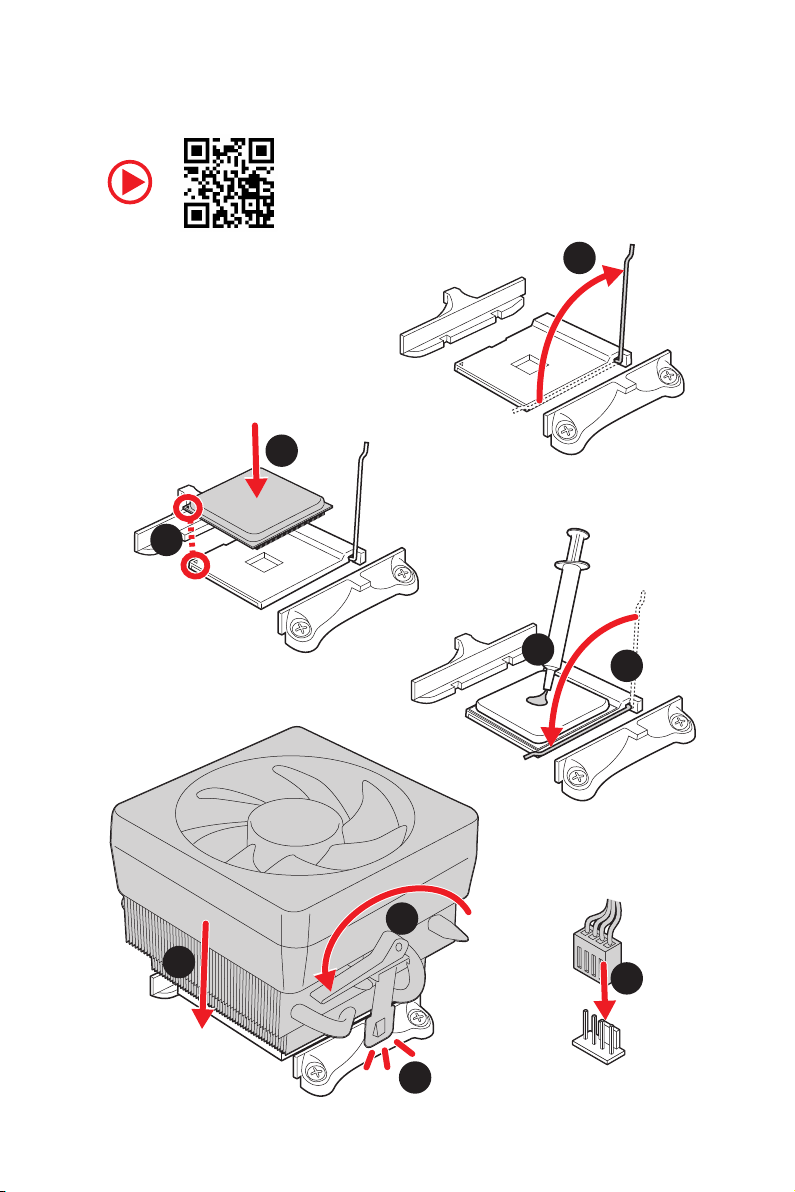
Installing a Processor
1
2
3
6
4
5
7
8
9
https://youtu.be/Xv89nhFk1vc
4
Quick Start
1
2
3
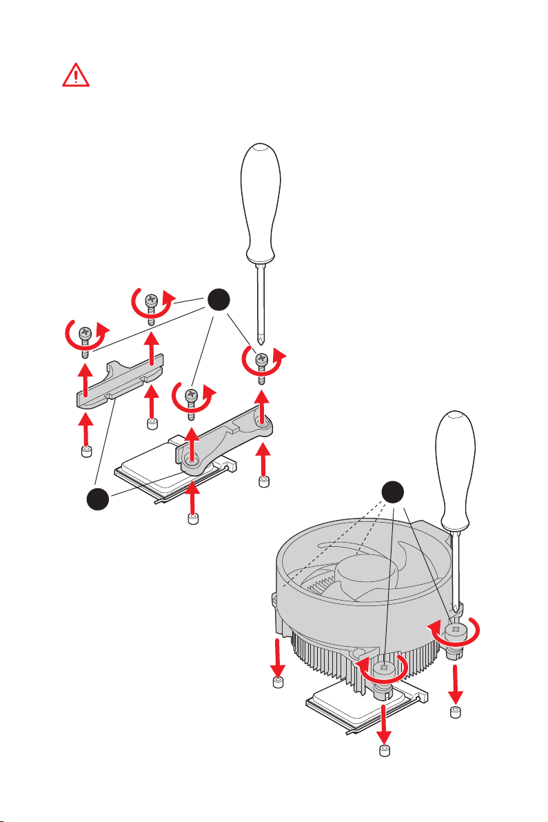
Important
If you are installing the screw-type CPU heatsink, please follow the figure below to
remove the retention module first and then install the heatsink.
5
Quick Start
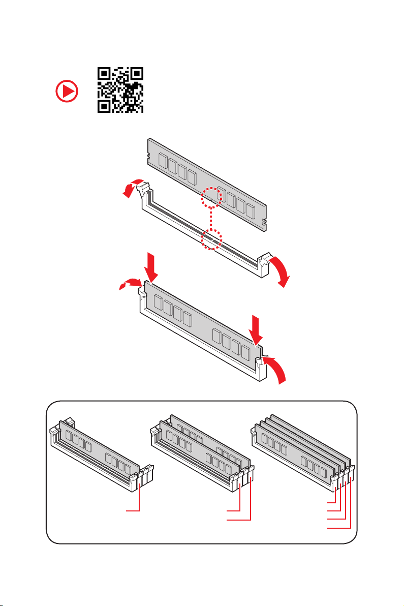
Installing DDR4 memory
http://youtu.be/T03aDrJPyQs
DIMMA2 DIMMA2
DIMMB2
DIMMA1
DIMMA2
DIMMB1
DIMMB2
6
Quick Start
HDD LED
RESET SW
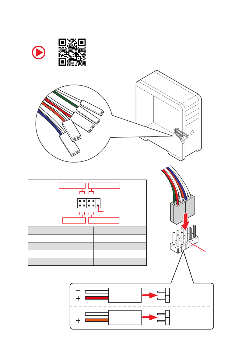
Connecting the Front Panel Header
http://youtu.be/DPELIdVNZUI
JFP1
HDD LED
HDD LED -
HDD LED +
POWER LED -
POWER LED +
POWER LED
1
2 10
9
+
+
+-
--
-
+
Power LED
HDD LED Reset Switch
Reserved
Power Switch
JFP1
1 HDD LED + 2 Power LED +
3 HDD LED - 4 Power LED -
5 Reset Switch 6 Power Switch
7 Reset Switch 8 Power Switch
9 Reserved 10 No Pin
RESET SW
POWER SW
POWER LED+
POWER LED-
HDD LED
7
Quick Start
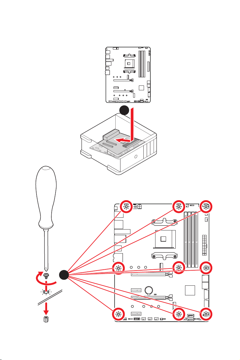
BAT1
Installing the MotherboardInstalling the Motherboard
1
2
8
Quick Start
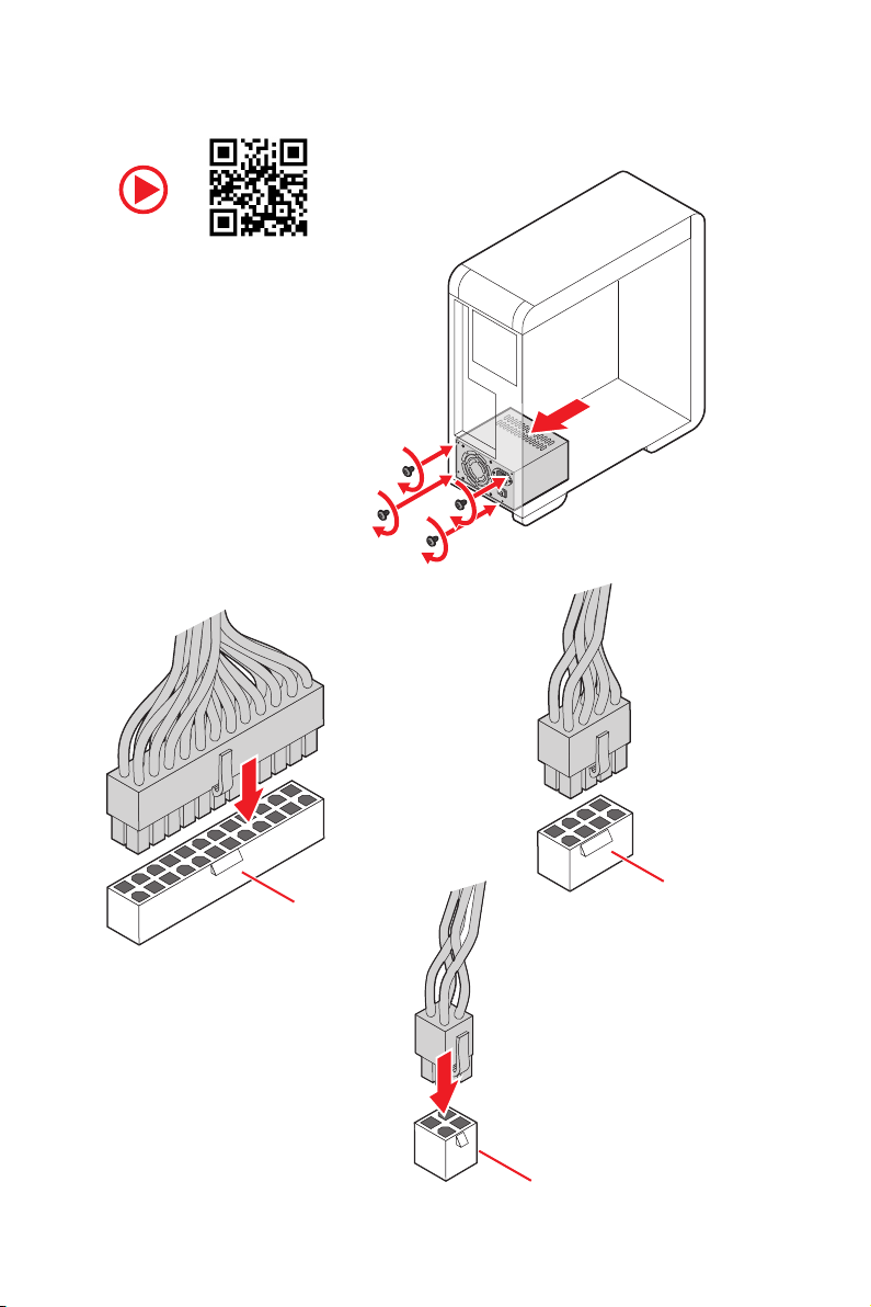
Connecting the Power Connectors
ATX_PWR1
CPU_PWR1
CPU_PWR2
http://youtu.be/gkDYyR_83I4
9
Quick Start
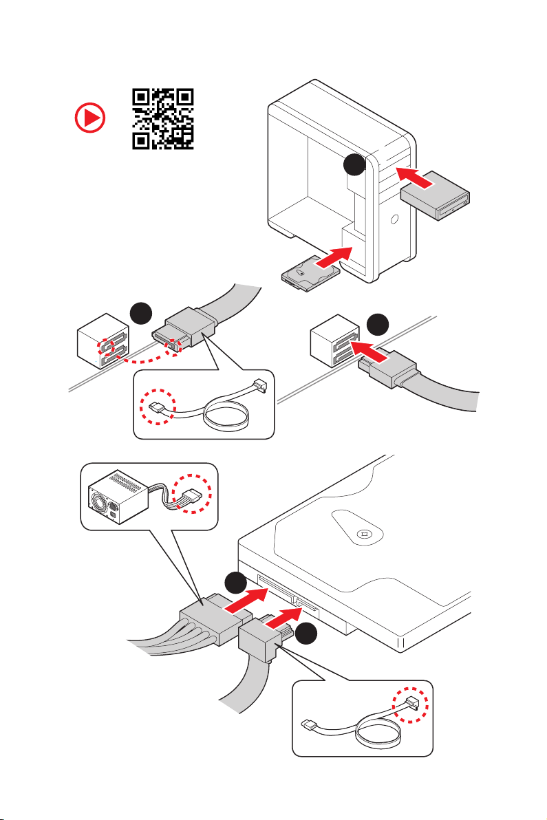
Installing SATA Drives
1
2
3
4
5
http://youtu.be/RZsMpqxythc
10
Quick Start
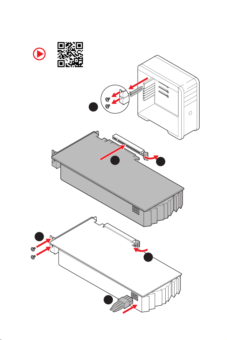
1
Installing a Graphics Card
http://youtu.be/mG0GZpr9w_A
2
3
4
5
6
11
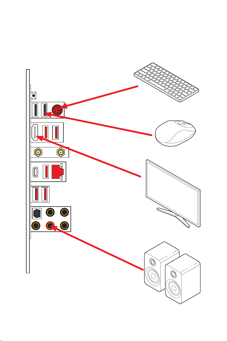
Quick Start
Connecting Peripheral Devices
Integrated Graphics Processing
Unit (iGPU)
12
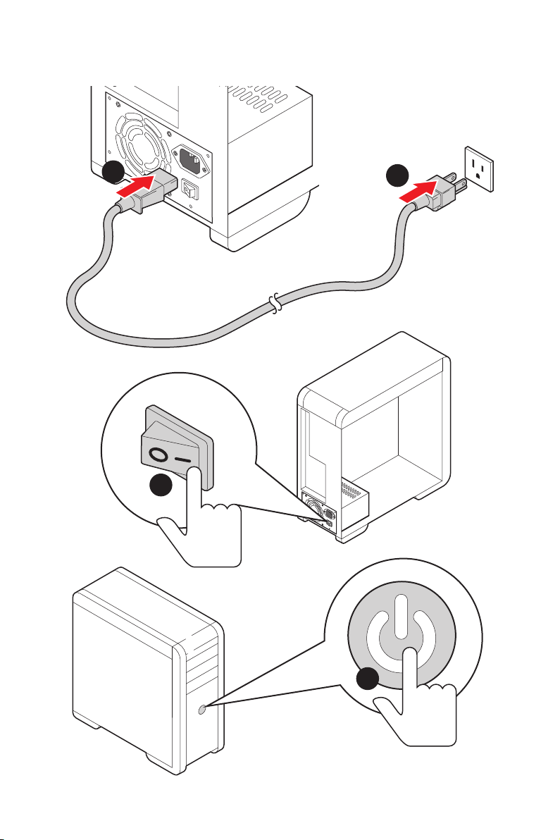
Quick Start
Power On
4
3
1
2

13
Contents
Contents
Quick Start ............................................................................................................. 1
Preparing Tools and Components .......................................................................... 1
Safety Information .................................................................................................. 2
Installing a Processor ............................................................................................. 3
Installing DDR4 memory ........................................................................................ 5
Connecting the Front Panel Header ....................................................................... 6
Installing the Motherboard ..................................................................................... 7
Installing the Motherboard ..................................................................................... 7
Connecting the Power Connectors ......................................................................... 8
Installing SATA Drives............................................................................................. 9
Installing a Graphics Card .................................................................................... 10
Connecting Peripheral Devices ............................................................................ 11
Power On............................................................................................................... 12
Safety Information ............................................................................................... 15
Specifications ....................................................................................................... 16
JCORSAIR1 Connector Specification .................................................................... 21
Package contents................................................................................................. 22
Block Diagram .................................................................................................... 23
Rear I/O Panel ...................................................................................................... 24
LAN Port LED Status Table................................................................................... 24
Audio Ports Configuration .................................................................................... 24
Realtek Audio Console ......................................................................................... 25
Overview of Components .................................................................................... 28
Processor Socket .................................................................................................. 30
DIMM Slots ............................................................................................................ 31
PCI_E1~4: PCIe Expansion Slots .......................................................................... 32
M2_1~2: M.2 Slots (Key M) ................................................................................... 33
SATA1~6: SATA 6Gb/s Connectors ....................................................................... 34
JFP1, JFP2: Front Panel Connectors ................................................................... 34
CPU_PWR1~2, ATX_PWR1: Power Connectors ................................................... 35
JUSB1~2: USB 2.0 Connectors ............................................................................. 36
JUSB3~4: USB 3.2 Gen1 Connector ..................................................................... 36
CPU_FAN1, PUMP_FAN1, SYS_FAN1~4: Fan Connectors ................................... 37
JAUD1: Front Audio Connector ............................................................................38
JCI1: Chassis Intrusion Connector ....................................................................... 38
JTPM1: TPM Module Connector ........................................................................... 39
JBAT1: Clear CMOS (Reset BIOS) Jumper ........................................................... 39

14
Contents
JRGB1: RGB LED connector ................................................................................. 40
JRAINBOW1~2: Addressable RGB LED connectors ............................................. 41
JCORSAIR1: CORSAIR Connector ........................................................................ 42
Onboard LEDs ...................................................................................................... 43
EZ Debug LED ....................................................................................................... 43
JPWRLED1: LED light demonstration power input connector ............................ 43
Installing OS, Drivers & Utilities ......................................................................... 44
Installing Windows
®
10 ......................................................................................... 44
Installing Drivers .................................................................................................. 44
Installing Utilities ................................................................................................. 44
BIOS Setup ........................................................................................................... 45
Entering BIOS Setup ............................................................................................. 45
Resetting BIOS ...................................................................................................... 46
Updating BIOS ....................................................................................................... 46
EZ Mode ................................................................................................................ 48
Advanced Mode .................................................................................................... 50
SETTINGS .............................................................................................................. 51
Advanced ............................................................................................................... 51
Boot ....................................................................................................................... 56
Security ................................................................................................................. 57
Save & Exit ............................................................................................................ 58
OC .......................................................................................................................... 59
M-FLASH .............................................................................................................. 62
OC PROFILE .......................................................................................................... 63
HARDWARE MONITOR .......................................................................................... 64
Nahimic 3 ............................................................................................................. 65
Installation and Update ........................................................................................ 65
Audio Tab ..............................................................................................................65
Microphone Tab .................................................................................................... 66
Sound Tracker Tab ................................................................................................ 67
Settings Tab .......................................................................................................... 67
AMD RAID Configuration ..................................................................................... 68
Enabling RAIDXpert2 Configuration Utility .......................................................... 68
Initializing Disks ................................................................................................... 69
Creating Arrays ..................................................................................................... 70
Deleting Arrays ..................................................................................................... 71
Installing RAID Driver ........................................................................................... 72
Troubleshooting .................................................................................................. 73

15
Safety Information
Safety Information
y The components included in this package are prone to damage from electrostatic
discharge (ESD). Please adhere to the following instructions to ensure successful
computer assembly.
y Ensure that all components are securely connected. Loose connections may cause
the computer to not recognize a component or fail to start.
y Hold the motherboard by the edges to avoid touching sensitive components.
y It is recommended to wear an electrostatic discharge (ESD) wrist strap when
handling the motherboard to prevent electrostatic damage. If an ESD wrist strap is
not available, discharge yourself of static electricity by touching another metal object
before handling the motherboard.
y Store the motherboard in an electrostatic shielding container or on an anti-static pad
whenever the motherboard is not installed.
y Before turning on the computer, ensure that there are no loose screws or metal
components on the motherboard or anywhere within the computer case.
y Do not boot the computer before installation is completed. This could cause
permanent damage to the components as well as injury to the user.
y If you need help during any installation step, please consult a certified computer
technician.
y Always turn off the power supply and unplug the power cord from the power outlet
before installing or removing any computer component.
y Keep this user guide for future reference.
y Keep this motherboard away from humidity.
y Make sure that your electrical outlet provides the same voltage as is indicated on the
PSU, before connecting the PSU to the electrical outlet.
y Place the power cord such a way that people can not step on it. Do not place anything
over the power cord.
y All cautions and warnings on the motherboard should be noted.
y If any of the following situations arises, get the motherboard checked by service
personnel:
Liquid has penetrated into the computer.
The motherboard has been exposed to moisture.
The motherboard does not work well or you can not get it work according to user
guide.
The motherboard has been dropped and damaged.
The motherboard has obvious sign of breakage.
y Do not leave this motherboard in an environment above 60°C (140°F), it may damage
the motherboard.
16
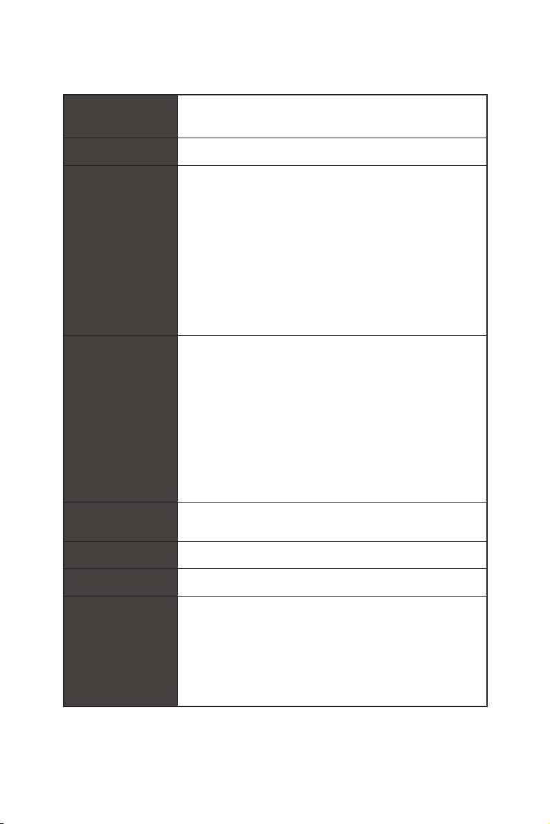
Specifications
Specifications
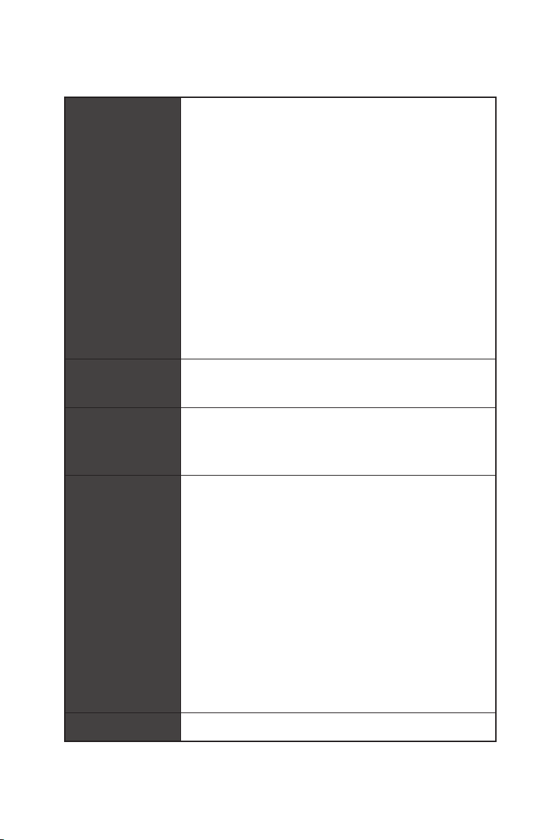
CPU
Supports 2nd and 3rd Gen AMD Ryzen™ / Ryzen™ with
Radeon™ Vega Graphics and 2nd Gen AMD Ryzen™ with
Radeon™ Graphics Desktop Processors for Socket AM4
Chipset AMD
®
X570 Chipset
Memory
y 4x DDR4 memory slots, support up to 128GB (depending
on the processor)
Supports 1866/ 2133/ 2400/ 2666Mhz by JEDEC, 2666/
2800/ 2933/ 3000/ 3066/ 3200/ 3466/ 3600/ 3733/ 3866/
4000/ 4133/ 4266/ 4400 by A-XMP OC mode
y Dual channel memory architecture
y Supports non-ECC UDIMM memory
y Supports ECC UDIMM memory (non-ECC mode)
y
Supports un-buffered memory
* Please refer www.msi.com for more information on compatible memory.
Expansion Slots
y 1x PCIe 4.0/3.0 x16 slot (PCI_E1)
3rd Gen AMD Ryzen™ support PCIe 4.0 x16 mode
2nd Gen AMD Ryzen™ support PCIe 3.0x16 mode
Ryzen™ with Radeon™ Vega Graphics and 2nd Gen
AMD Ryzen™ with Radeon™ Graphics support PCIe 3.0
x8 mode
y 1x PCIe 4.0/3.0 x16 slot (PCI_E3, supports x4 mode)
y 2x PCIe 3.0 x1 slots
*The speeds may vary for different devices
Onboard Graphics
y 1x HDMI 1.4 port, supports a maximum resolution of
4096x2160 @24Hz
Multi-GPU Supports 2-Way AMD
®
CrossFire™ Technology
LAN 1x Intel
®
I211AT Gigabit LAN controller
WiFi & Bluetooth
Intel
®
Wi-Fi 6 AX200
y The Wireless module is pre-install in the M2_WIFI1 (Key-E)
slot
y Supports 802.11 a/b/g/n/ac/ax, MU-MINO Rx, 2.4GHz-
5GHz (160MHz) up to 2.4Gbps
y Supports Bluetooth
®
5
Continued on next page
17
Specifications
Continued from previous page
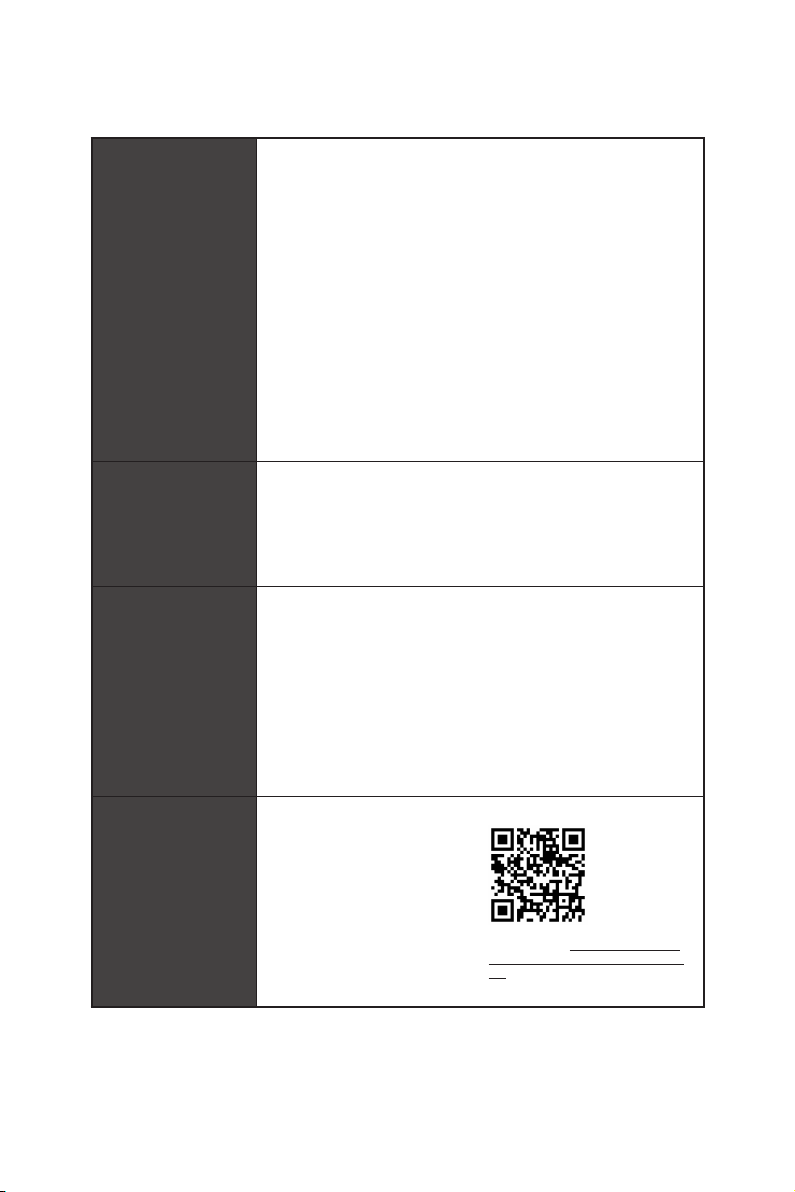
Storage
y AMD
®
X570 Chipset
4x SATA 6Gb/s ports (SATA1~SATA4)
y ASMedia ASM1061
2x SATA 6Gb/s ports (SATA5~SATA6)
y 2x M.2 slots (Key M)*
M2_1 slot (from AMD
®
Processor) supports PCIe 4.0
x4 (3rd Gen AMD Ryzen™ Desktop Processors) or PCIe
3.0 x4 (2nd Gen AMD Ryzen™/ Ryzen™ with Radeon™
Vega Graphics and 2nd Gen AMD Ryzen™ with Radeon™
Graphics) 2242/2260/2280 storage devices
M2_2 slot (from AMD
®
X570 Chipset) supports PCIe
4.0 x4 (3rd Gen AMD Ryzen™) or 3.0 x4 (2nd Gen AMD
Ryzen™/ Ryzen™ with Radeon™ Vega Graphics and 2nd
Gen AMD Ryzen™ with Radeon™ Graphics) and SATA
6Gb/s 2242/ 2260/ 2280/ 22110 storage devices
*The speeds may vary for different devices
RAID
AMD
®
X570 Chipset
y Supports RAID 0, RAID 1 and RAID 10
Audio
Realtek
®
ALC1220 Codec
y 7.1-Channel High Definition Audio
y Supports Optical S/PDIF output
USB
AMD
®
X570 Chipset
2x USB 3.2 Gen2 (SuperSpeed USB 10Gbps) Type-A
ports on the back panel
4x USB 3.2 Gen1 (SuperSpeed USB) ports available
through the internal USB 3.2 Gen1 connector
6x USB 2.0 (High-speed USB) ports (2 Type-A ports on
the back panel, 4 ports available through the internal
USB 2.0 connectors)
AMD
®
Processor
2x USB 3.2 Gen2 (3rd Gen AMD Ryzen™) or USB 3.2
Gen1 (2nd Gen AMD Ryzen™/ Ryzen™ with Radeon™
Vega Graphics and 2nd Gen AMD Ryzen™ with Radeon™
Graphics) Type-A and Type-C port on the back panel
2x USB 3.2 Gen1 (SuperSpeed USB) Type-A ports on the
back panel
I/O Controller NUVOTON NCT6797 Controller Chip
Continued on next page

18
Specifications
Continued from previous page
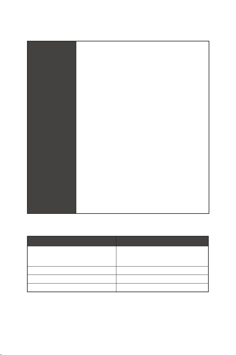
Hardware Monitor
y CPU/System/Chipset temperature detection
y CPU/System/Chipset fan speed detection
y CPU/System/Chipset fan speed control
Form Factor
y ATX Form Factor
y 12 in. x 9.6 in. (30.4 cm x 24.3 cm)
Internal Connectors
y 1x 24-pin ATX main power connector
y 1x 8-pin ATX 12V power connector
y 1x 4-pin ATX 12V power connector
y 6x SATA 6Gb/s connectors
y 2x USB 2.0 connectors (supports additional 4 USB 2.0
ports)
y 2x USB 3.2 Gen1 connectors (supports additional 4 USB 3.2
Gen1 ports)
y 1x 4-pin CPU fan connector
y 1x 4-pin water-pump connector
y 4x 4-pin system fan connectors
y 1x Front panel audio connector
y 2x System panel connectors
y 1x TPM module connector
y 1x Clear CMOS jumper
y 1x Chassis Intrusion connector
y 1x 4-pin RGB LED connector
y 2x 3-pin RAINBOW LED connectors
y 1x 3-pin CORSAIR connector
y 1x 2-pin LED Demo Connect
y 4x EZ Debug LEDs
Continued on next page
19
Specifications
Continued from previous page
Back Panel
Connectors
y 1x Flash BIOS Button
y 1x PS/2 keyboard/ mouse combo port
y 2x USB 2.0 ports
y 2x USB 3.2 Gen1 ports
y 1x HDMI port
y 2x WiFi/ Bluetooth antenna jacks
y 1x LAN(RJ45) port
y 3x USB 3.2 Gen2 Type A ports
y 1x USB 3.2 Gen2 Type C port
y 5x OFC audio jacks
y 1x Optical S/PDIF Out connector
BIOS Features
y 1x 256 Mb flash
y UEFI AMI BIOS
y ACPI 6.1, SM BIOS 2.8
y Multi-language
Software
y Drivers
y DRAGON CENTER
y Nahimic Audio
y CPU-Z MSI GAMING
y MSI App Player (BlueStacks)
y Google Chrome™, Google Toolbar, Google Drive
y Norton™ Internet Security Solution
Dragon Center
Features
y DRAGON OPTIMIZATION
y OC Performance
y Hardware Monitor
y LAN Manager
y True Color
y Mystic Light
y Live update
Please refer to http://download.msi.
com/manual/mb/DRAGONCENTER2.
pdf for more details.
Continued on next page

20
Specifications
Continued from previous page
Special Features
y Audio
Audio Boost 4
Nahimic3
Voice Boost
y Network
GAMING LAN with Gaming LAN Manager
Intel WiFi
y Storage
Twin Lightning Gen 4 M.2
Twin Turbo M.2
y Cooling
Frozr Heatsink Design
Propeller Blade Technology
M.2 Shield Frozr
Pump Fan
Gaming Fan Control
y LED
Mystic Light
Mystic Light Extension (RGB)
Mystic Light Extension (RAINBOW)
Mystic Light Extension(CORSAIR)
Mystic light SYNC
EZ DEBUG LED
y Protection
PCI-E Steel Armor
Pre-installed IO shielding
Continued on next page
21
Specifications
Continued from previous page
Special Features
y Performance
Lightning Gen 4 PCI-E Slot
Multi GPU-CrossFire Technology
DDR4 Boost
Core Boost
GAME Boost
USB with type A+C
AMD Turbo USB 3.2 Gen 2
Dual CPU Power
y Gamer Experience
DRAGON CENTER
GAMING HOTKEY
GAMING MOUSE Control
USB SPEED UP
Total Fan control
Live Update
APP Player
y BIOS
Click BIOS 5
Flash BIOS Button
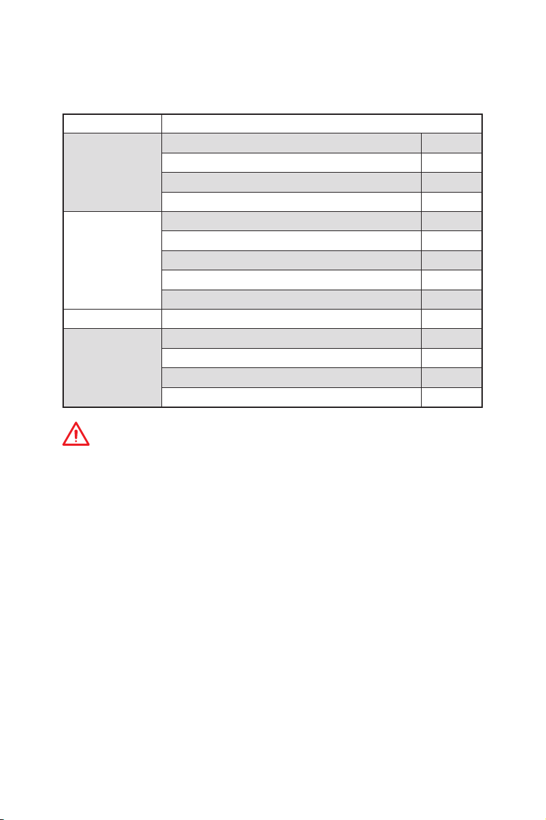
JCORSAIR1 Connector Specification
Supporting CORSAIR RGB Products Maximum connection
Lighting Node PRO LED Strip
20*
* 20% brightness is recommended when the number of
LED strips exceeds 8.
HD120 RGB Fan 6
SP120 RGB Fan 6
LL120 RGB Fan 6
22
Package contents
Package contents
Please check the contents of your motherboard package. It should contain:
Motherboard MPG X570 GAMING PRO CARBON WIFI
Cable
SATA 6Gb/s Cables 2
1 to 2 RGB LED Extension Y Cable 80cm 1
CORSAIR RGB LED Extension Cable 50cm 1
RAINBOW RGB LED Extension Cable 80cm 1
Accessories
Antenna Set 1
8.5H M.2 screws 2
Case Badge 1
SATA Cable Labels 1
Product Registration Card 1
Application DVD Driver DVD 1
Documentation
User Manual 1
Quick Installation Guide 1
Case Stand-off Notification 1
SHOUTOUT 2.0 DM 1
Important
If any of the above items are damaged or missing, please contact your retailer.
23
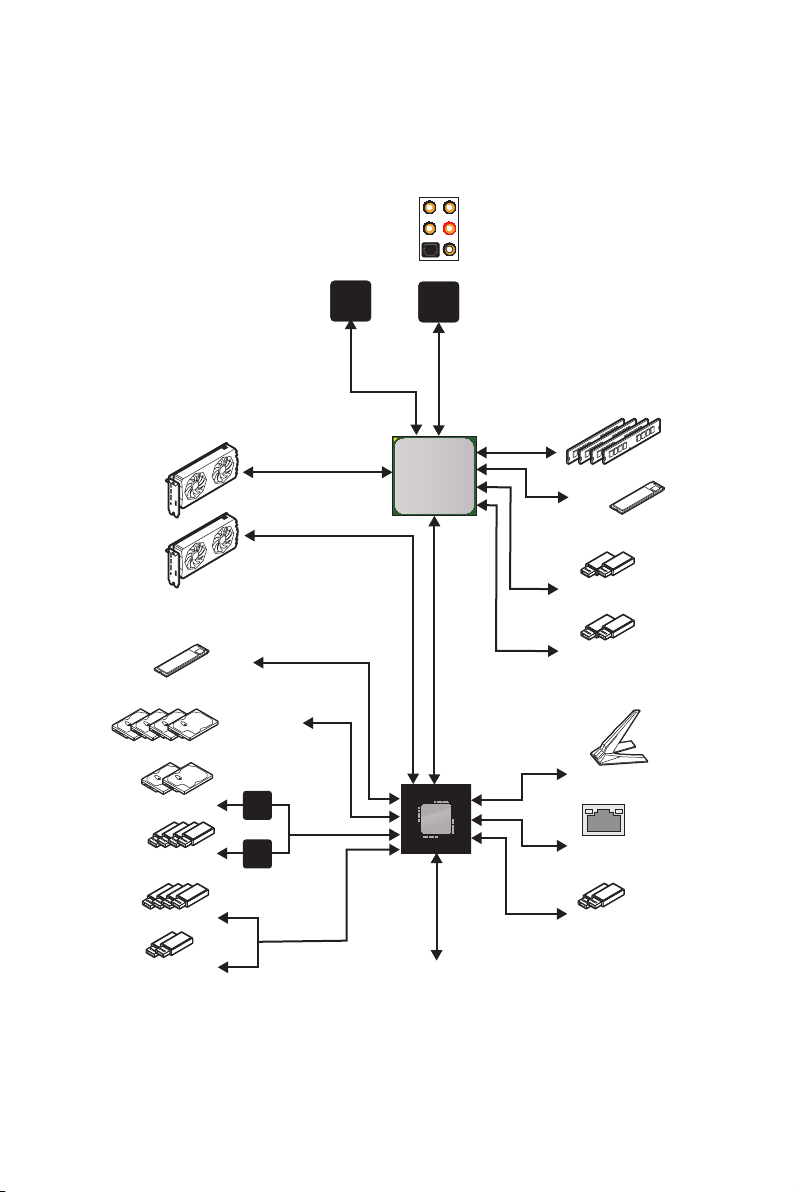
Block Diagram
Block Diagram
2 Channel DDR4 Memory
2x USB 3.2 Gen1
PCIE
PCH
Processor
NUVOTON
6797
Realtek
ALC1220
4x USB 3.2 Gen1
2x USB 3.2 Gen2
2x PCIe x1
4x USB 2.0
GL850G
ASM
1061
Rear Audio Jacks
1x M.2
1x Intel I211
1x Intel Wi-Fi 6 AX200
2x SATA 6Gb/s
4x SATA 6Gb/s
1x M.2
2x USB 2.0
2x USB 3.2 Gen2
24
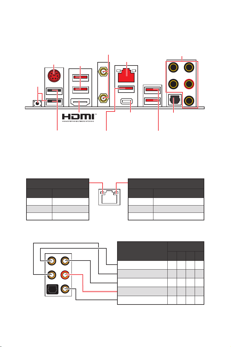
Rear I/O Panel
USB 3.2 Gen2
Type-C
USB 3.2 Gen2
Type-A
Link/ Activity LED
Status Description
Off No link
Yellow Linked
Blinking Data activity
Speed LED
Status Description
Off 10 Mbps connection
Green 100 Mbps connection
Orange 1 Gbps connection
LAN Port LED Status Table
Audio Ports Configuration
Audio Ports
Channel
2 4 6 8
Center/ Subwoofer Out ● ●
Rear Speaker Out ● ● ●
Line-In/ Side Speaker Out ●
Line-Out/ Front Speaker Out ● ● ● ●
Mic In
(●: connected, Blank: empty)
Rear I/O Panel
PS/2
LAN
USB 2.0 Type-A
Audio Ports
Optical S/PDIF-Out
Flash BIOS
Button & Port
USB 3.2 Gen2
Type-A
USB 3.2 Gen1
Type-A
y Flash BIOS Button/Port - Please refer to page 49 for Updating BIOS with Flash BIOS
Button.
Wi-Fi Antenna
connectors
Loading...