


Thank you for purchasing the MSI® motherboard H110I PRO. This User Guide gives information about board layout, component overview and BIOS setup.
Contents |
|
Safety Information........................................................................................... |
2 |
Specifications................................................................................................... |
3 |
Rear I/O Panel ................................................................................................. |
5 |
LAN Port LED Status Table ................................................................................ |
5 |
Overview of Components ................................................................................ |
6 |
CPU Socket......................................................................................................... |
7 |
DIMM Slots ......................................................................................................... |
8 |
PCI_E1: PCIe Expansion Slot ............................................................................. |
8 |
SATA1~4: SATA 6Gb/s Connectors..................................................................... |
9 |
JFP1, JFP2: Front Panel Connectors................................................................. |
9 |
M2_2: M.2 Slot.................................................................................................. |
10 |
JPWR1~2: Power Connectors .......................................................................... |
11 |
JUSB1: USB 2.0 Connector .............................................................................. |
11 |
JUSB2: USB 3.1 Gen1 Connector..................................................................... |
12 |
JAUD1: Front Audio Connector ........................................................................ |
12 |
JCOM1: Serial Port Connector......................................................................... |
12 |
CPUFAN, SYSFAN1: Fan Connectors ............................................................... |
13 |
JCI1: Chassis Intrusion Connector .................................................................. |
14 |
JBAT1: Clear CMOS (Reset BIOS) Jumper....................................................... |
14 |
BIOS Setup..................................................................................................... |
15 |
Entering BIOS Setup......................................................................................... |
15 |
Resetting BIOS ................................................................................................. |
16 |
Updating BIOS .................................................................................................. |
16 |
Software Description..................................................................................... |
17 |
Installing Windows® 7/ 8.1/ 10 ......................................................................... |
17 |
Installing Drivers.............................................................................................. |
17 |
Installing Utilities ............................................................................................. |
17 |
Contents 1
Safety Information
yThe components included in this package are prone to damage from electrostatic discharge (ESD). Please adhere to the following instructions to ensure successful computer assembly.
yEnsure that all components are securely connected. Loose connections may cause the computer to not recognize a component or fail to start.
yHold the motherboard by the edges to avoid touching sensitive components.
yIt is recommended to wear an electrostatic discharge (ESD) wrist strap when handling the motherboard to prevent electrostatic damage. If an ESD wrist strap is not available, discharge yourself of static electricity by touching another metal object before handling the motherboard.
yStore the motherboard in an electrostatic shielding container or on an anti-static pad whenever the motherboard is not installed.
yBefore turning on the computer, ensure that there are no loose screws or metal components on the motherboard or anywhere within the computer case.
yDo not boot the computer before installation is completed. This could cause permanent damage to the components as well as injury to the user.
yIf you need help during any installation step, please consult a certified computer technician.
yAlways turn off the power supply and unplug the power cord from the power outlet before installing or removing any computer component.
yKeep this user guide for future reference.
yKeep this motherboard away from humidity.
yMake sure that your electrical outlet provides the same voltage as is indicated on the PSU, before connecting the PSU to the electrical outlet.
yPlace the power cord such a way that people can not step on it. Do not place anything over the power cord.
yAll cautions and warnings on the motherboard should be noted.
yIf any of the following situations arises, get the motherboard checked by service personnel:
Liquid has penetrated into the computer.
The motherboard has been exposed to moisture.
The motherboard does not work well or you can not get it work according to user guide.
The motherboard has been dropped and damaged.
The motherboard has obvious sign of breakage.
yDo not leave this motherboard in an environment above 60°C (140°F), it may damage the motherboard.
2 Safety Information

Specifications
CPU |
Supports 6th Gen Intel® Core™ i3/i5/i7 processors, and Intel® |
|
Pentium® and Celeron® processors for Socket LGA1151 |
||
|
||
Chipset |
y Intel® H110 Chipset |
|
|
y 2x DDR4 memory slots, support up to 32GB |
|
|
Supports DDR4 2133 MHz* |
|
Memory |
y Dual channel memory architecture |
|
y Supports Intel® Extreme Memory Profile (XMP) |
||
|
||
|
* Please refer to www.msi.com for more information on |
|
|
compatible memory. |
|
Expansion Slots |
y 1x PCIe 3.0 x16 slot |
|
|
|
|
|
y 1x HDMI™ port, supports a maximum resolution of |
|
Onboard Graphics |
4096x2160@24Hz, 2560x1600@60Hz |
|
y 1x DVI-D port, supports a maximum resolution of |
||
|
1920x1200@60Hz |
|
|
Intel® H110 Chipset |
|
|
y 4x SATA 6Gb/s ports |
|
Storage |
y 1xM.2 slot |
|
|
supports PCIe 2.0x4 standard, 4.2cm/6cm/8cm length M.2 |
|
|
PCIe-interface SSD cards |
|
|
y Intel® H110 Chipset |
|
|
4x USB 3.1 Gen1 (SuperSpeed USB) ports (2 ports on the |
|
USB |
back panel, 2 ports available through the internal USB |
|
connector) |
||
|
6x USB 2.0 (High-speed USB) ports (4 ports on the |
|
|
back panel, 2 ports available through the internal USB |
|
|
connectors) |
|
Audio |
y Realtek® ALC887 Codec |
|
y 7.1-Channel High Definition Audio |
||
|
||
|
|
|
LAN |
1x Realtek® RTL8111H Gigabit LAN controller |
|
|
y 1x PS/2 keyboard/ mouse combo port |
|
|
y 4x USB 2.0 ports |
|
Back Panel |
y 1x DVI-D port |
|
y 2x USB 3.1 Gen1 ports |
||
Connectors |
||
y 1x HDMI™ port |
||
|
||
|
y 1x LAN (RJ45) port |
|
|
y 3x audio jacks |
|
|
|
|
|
Continued on next page |
Specifications 3

Continued from previous page
|
y 1x 24-pin ATX main power connector |
|
|
y 1x 4-pin ATX 12V power connector |
|
|
y 4x SATA 6Gb/s connectors |
|
|
y 1x USB 2.0 connector (supports additional 2 USB 2.0 ports) |
|
|
y 1x USB 3.1 Gen1 connector (supports additional 2 USB 3.1 |
|
Internal |
Gen1 ports) |
|
y 1x 4-pin CPU fan connector |
||
Connectors |
||
y 1x 4-pin system fan connector |
||
|
||
|
y 1x Front panel audio connector |
|
|
y 2x Front panel connectors |
|
|
y 1x Serial Port connector |
|
|
y 1x Chassis Intrusion connector |
|
|
y 1x Clear CMOS jumper |
|
I/O Controller |
NUVOTON NCT5563 Controller Chip |
|
|
|
|
Hardware |
y CPU/System temperature detection |
|
y CPU/System fan speed detection |
||
Monitor |
||
y CPU/System fan speed control |
||
|
||
Form Factor |
y Mini-ITX Form Factor |
|
y 6.7 in. x 6.7 in. (17.0 cm x 17.0 cm) |
||
|
||
|
|
|
|
y 1x 64 Mb flash |
|
BIOS Features |
y UEFI AMI BIOS |
|
y ACPI 5.0, PnP 1.0a, SM BIOS 2.8 |
||
|
||
|
y Multi-language |
|
|
|
|
|
y Drivers |
|
|
y COMMAND CENTER |
|
|
y LIVE UPDATE 6 |
|
|
y FAST BOOT |
|
|
y SUPER CHARGER |
|
|
y M-CLOUD |
|
Software |
y RAMDISK |
|
|
y Intel® Small Business Basics |
|
|
y Network Genie |
|
|
y Intel® Extreme Tuning Utility |
|
|
y Norton™ Security |
|
|
y Google Chrome™,Google Toolbar, Google Drive |
|
|
y CPU-Z |
4 Specifications
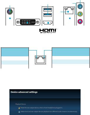
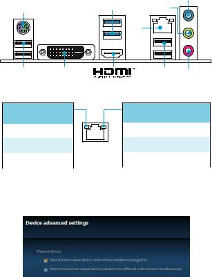
Rear I/O Panel
|
|
Line-in |
PS/2 |
USB 3.1 Gen1 |
Line-out |
|
|
LAN |
|
|
|
|
|
|
|
|
|
|
|
|
|
|
|
|
|
|
|
|
|
|
|
|
|
|
|
|
|
|
|
|
|
|
|
|
|
|
|
|
|
|
|
|
|
|
|
|
|
|
|
|
|
|
|
|
|
|
|
|
|
|
|
|
|
|
|
|
|
|
|
|
|
|
|
|
|
|
|
|
|
|
|
|
|
|
|
|
|
|
|
|
|
|
|
|
|
|
|
|
|
|
|
|
|
|
|
|
|
|
|
|
|
|
|
|
|
|
|
|
|
USB 2.0 |
DVI-D |
|
|
USB 2.0 Mic |
in |
|||||||||
LAN Port LED Status Table
Link/ Activity LED
Status |
Description |
|
|
Off |
No link |
|
|
Yellow |
Linked |
|
|
Blinking |
Data activity |
Speed LED
Status |
Description |
|
|
Off |
10 Mbps connection |
|
|
Green |
100 Mbps connection |
|
|
Orange |
1 Gbps connection |
|
|
Audio 7.1-channel Configuration
To configure 7.1-channel audio, you have to connect front audio I/O module to JAUD1 connector and follow the below steps.
1.Click on the Realtek HD Audio Manager > Advanced Settings to open the dialog below.
2.Select Mute the rear output device, when a front headphone plugged in.
3.Plug your speakers to audio jacks on rear and front I/O panel. When you plug into a device at an audio jack, a dialogue window will pop up asking you which device is current connected.
Rear I/O Panel 5
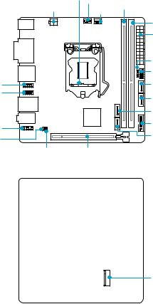
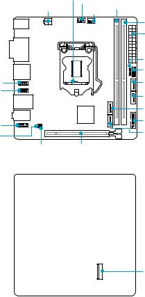
Overview of Components
Top view
|
CPU Socket |
|
|
||
JPWR2 |
|
|
CPUFAN |
|
DIMM1 |
|
|
|
|||
|
|
SYSFAN1 |
|
||
|
|
|
|
||
DIMM2
JPWR1
|
JFP2 |
|
JFP1 |
JCOM1 |
SATA1 |
JUSB1 |
SATA2 |
|
|
|
SATA3 |
JAUD1 |
JUSB2 |
|
|
JBAT1 |
SATA4 |
|
|
JCI1 |
PCI_E1 |
Bottom view
M2_2
6 Overview of Components
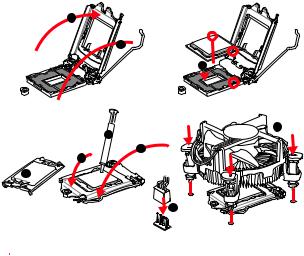
CPU Socket
Please install the CPU into the CPU socket as shown below.
2
1
3


 8 7
8 7 


5
 4 6
4 6


9
 Important
yAlways unplug the power cord from the power outlet before installing or removing the CPU.
yPlease retain the CPU protective cap after installing the processor. MSI will deal with Return Merchandise Authorization (RMA) requests if only the motherboard comes with the protective cap on the CPU socket.
yWhen installing a CPU, always remember to install a CPU heatsink. A CPU heatsink is necessary to prevent overheating and maintain system stability.
yConfirm that the CPU heatsink has formed a tight seal with the CPU before booting your system.
yOverheating can seriously damage the CPU and motherboard. Always make sure the cooling fans work properly to protect the CPU from overheating. Be sure to apply an even layer of thermal paste (or thermal tape) between the CPU and the heatsink to enhance heat dissipation.
yWhenever the CPU is not installed, always protect the CPU socket pins by covering the socket with the plastic cap.
yIf you purchased a separate CPU and heatsink/ cooler, Please refer to the documentation in the heatsink/ cooler package for more details about installation.
Overview of Components 7
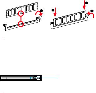
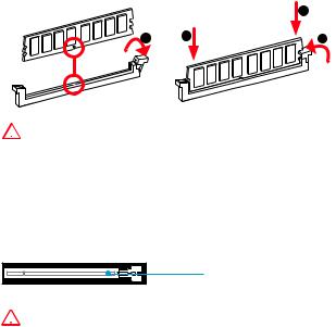
DIMM Slots
Please install the memory module into the DIMM slot as shown below.
2
1 |
2 |
3 |
 Important
yDue to chipset resource usage, the available capacity of memory will be a little less than the amount of installed.
yPlease note that the maximum capacity of addressable memory is 4GB or less for 32-bit Windows OS due to the memory address limitation. Therefore, we
recommended that you to install 64-bit Windows OS if you want to install more than 4GB memory on the motherboard.
PCI_E1: PCIe Expansion Slot
PCI_E1: PCIe 3.0 x16 slot
 Important
When adding or removing expansion cards, always turn off the power supply and unplug the power supply power cable from the power outlet. Read the expansion card’s documentation to check for any necessary additional hardware or software changes.
8 Overview of Components
SATA1~4: SATA 6Gb/s Connectors
These connectors are SATA 6Gb/s interface ports. Each connector can connect to one SATA device.
|
SATA1 |
SATA3 |
SATA2 |
|
|
SATA4 |
|
 Important
yPlease do not fold the SATA cable at a 90-degree angle. Data loss may result during transmission otherwise.
ySATA cable has identical plugs on either sides of the cable. However, it is recommended that the flat connector be connected to the motherboard for space saving purposes.
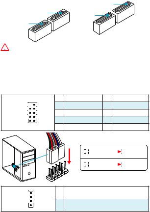
JFP1, JFP2: Front Panel Connectors
These connectors connect to the switches and LEDs on the front panel.
|
|
1 |
HDD LED + |
2 |
Power LED + |
10 |
9 |
3 |
HDD LED - |
4 |
Power LED - |
JFP1 |
|
5 |
Reset Switch |
6 |
Power Switch |
2 |
1 |
7 |
Reset Switch |
8 |
Power Switch |
|
|
9 |
Reserved |
10 |
No Pin |
HDDLED |
RESETSW |
|
JFP1 |
|
1 |
JFP2 |
|
1 |
3 |
|
HDD LED |
|
|
|
|
|
HDD LED - |
|
|
|
|
|
|
|
HDD LED + |
|
|
|
|
|
|
|
POWER LED - |
|
POWER LED |
|
|
|
|
|
POWER LED + |
|
|
|
|
|
|
|
Speaker - |
2 |
Buzzer + |
Buzzer - |
4 |
Speaker + |
|
|
|
Overview of Components 9
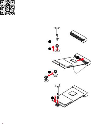
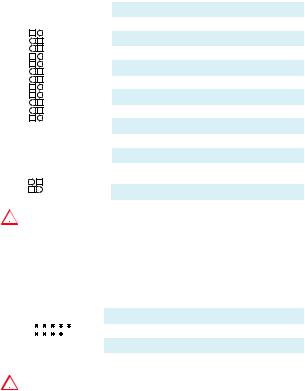
M2_2: M.2 Slot
 Video Demonstration
Watch the video to learn how to Install M.2 module. http://youtu.be/JCTFABytrYA
Installing M.2 module
1.Remove the screw from the base screw.
2.Remove the base screw.
3.Tighten the base screw into the hole of the distance to the M.2 slot as the length your M.2 module.
4.Insert your M.2 module into the M.2 slot at a 30-degree angle.
1

2
4 |
3 |
30° |
5. Put the screw in the notch |
5 |
on the trailing edge of your |
M.2 module and tighten it into the base screw.
 Important
Before you install the motherboard into the case, make sure the M.2 module has been installed properly.
10 Overview of Components
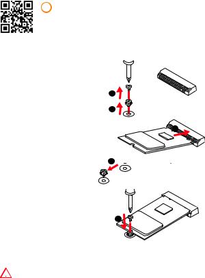
JPWR1~2: Power Connectors
These connectors allow you to connect an ATX power supply.
|
|
|
|
|
|
|
1 |
+3.3V |
13 |
+3.3V |
|
|
|
|
|
|
|
|
|
|
|
|
|
|
|
|
|
|
2 |
+3.3V |
14 |
-12V |
12 |
|
|
|
24 |
|
|
3 |
Ground |
15 |
Ground |
|
|
|
|
|
|
|
|
|
||
|
|
4 |
+5V |
16 |
PS-ON# |
|||||
|
|
|
|
|
|
|
||||
|
|
|
|
|
|
|
|
|
|
|
|
|
|
|
|
|
|
5 |
Ground |
17 |
Ground |
|
|
|
|
|
JPWR1 |
6 |
+5V |
18 |
Ground |
|
|
|
|
|
|
|
|
7 |
Ground |
19 |
Ground |
|
|
|
|
|
|
|
8 |
PWR OK |
20 |
Res |
|
|
|
|
|
|
|
|
|
|
|
1 |
|
|
|
13 |
|
|
9 |
5VSB |
21 |
+5V |
|
|
|
|
|
|
|
|
|
||
|
|
10 |
+12V |
22 |
+5V |
|||||
|
|
|
|
|
|
|
||||
|
|
|
|
|
|
|
11 |
+12V |
23 |
+5V |
|
|
|
|
|
|
|
|
|
|
|
|
|
|
|
|
|
|
12 |
+3.3V |
24 |
Ground |
|
|
|
|
|
|
|
|
|
|
|
3 |
|
|
|
1 |
JPWR2 |
1 |
Ground |
3 |
+12V |
|
4 |
|
|
|
2 |
|
2 |
Ground |
4 |
+12V |
|
|
|
|
|
|
|
|||||
 Important
Make sure that all the power cables are securely connected to a proper ATX power supply to ensure stable operation of the motherboard.
JUSB1: USB 2.0 Connector
This connector allows you to connect USB 2.0 ports on the front panel.
|
|
|
|
|
|
|
1 |
VCC |
2 |
VCC |
|
|
|
|
|
|
|
|
|
|
|
2 |
10 |
|
3 |
USB0- |
4 |
USB1- |
||||
|
|
|
|
|
|
|
5 |
USB0+ |
6 |
USB1+ |
|
|
|
|
|
|
|
|
|
|
|
1 |
9 |
|
7 |
Ground |
8 |
Ground |
||||
|
|
|
|
|
|
|
9 |
No Pin |
10 |
NC |
 Important
yNote that the VCC and Ground pins must be connected correctly to avoid possible damage.
yIn order to recharge your iPad,iPhone and iPod through USB ports, please install MSI® SUPER CHARGER utility.
Overview of Components 11

JUSB2: USB 3.1 Gen1 Connector
This connector allows you to connect USB 3.1 Gen1 ports on the front panel.
|
|
|
1 |
Power |
11 |
USB2.0+ |
|
|
|
|
|
|
|
|
|
|
2 |
USB3_RX_DN |
12 |
USB2.0- |
10 |
|
11 |
3 |
USB3_RX_DP |
13 |
Ground |
|
||||||
|
|
|
|
|
||
|
|
|
4 |
Ground |
14 |
USB3_TX_C_DP |
|
|
|
5 |
USB3_TX_C_DN |
15 |
USB3_TX_C_DN |
|
|
|
||||
|
|
|
|
|
|
|
|
|
|
6 |
USB3_TX_C_DP |
16 |
Ground |
|
|
|
||||
|
|
|
|
|
|
|
|
|
|
7 |
Ground |
17 |
USB3_RX_DP |
1 |
|
20 |
8 |
USB2.0- |
18 |
USB3_RX_DN |
|
|
|
9 |
USB2.0+ |
19 |
Power |
|
|
|
10 |
Ground |
20 |
No Pin |
 Important
Note that the Power and Ground pins must be connected correctly to avoid possible damage.
JAUD1: Front Audio Connector
This connector allow you to connect audio jacks on the front panel.
|
|
|
|
|
|
|
1 |
MIC L |
2 |
Ground |
|
|
|
|
|
|
|
|
|
|
|
2 |
10 |
|
3 |
MIC R |
4 |
NC |
||||
|
|
|
|
|
|
|
5 |
Head Phone R |
6 |
MIC Detection |
1 |
9 |
|
7 |
SENSE_SEND |
8 |
No Pin |
||||
|
|
|
|
|
|
|
|
|
|
|
|
|
|
|
|
|
|
9 |
Head Phone L |
10 |
Head Phone Detection |
JCOM1: Serial Port Connector
This connector allows you to connect the optional serial port with bracket.
|
|
|
|
|
|
|
1 |
DCD |
2 |
SIN |
|
|
|
|
|
|
|
|
|
|
|
2 |
10 |
|
3 |
SOUT |
4 |
DTR |
||||
|
|
|
|
|
|
|
5 |
Ground |
6 |
DSR |
|
|
|
|
|
|
|
|
|
|
|
1 |
9 |
|
7 |
RTS |
8 |
CTS |
||||
|
|
|
|
|
|
|
|
|
|
|
|
|
|
|
|
|
|
9 |
RI |
10 |
No Pin |
12 Overview of Components
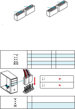
CPUFAN, SYSFAN1: Fan Connectors
Fan connectors can be classified as PWM (Pulse Width Modulation) Mode and Voltage Mode. PWM Mode fan connectors provide constant 12V output and adjust fan speed with speed control signal. Voltage Mode fan connectors control fan speed by changing voltage. Therefore, when you plug a 3-pin (Non-PWM) fan to a PWM Mode fan connector, the fan speed will be always maintained at 100%, and that could be noisy.
PWM Mode fan connector
1
CPUFAN
1 |
Ground |
2 |
+12V |
|
|
|
|
|
|
3 |
Sense |
4 |
Speed Control |
|
Signal |
||||
|
|
|
Voltage Mode fan connector
1
SYSFAN1
1 |
Ground |
2 |
Voltage |
|
Control |
||||
|
|
|
||
3 |
Sense |
4 |
NC |
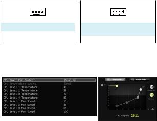
Controlling the fan speed
There are two ways to manage fan speed. One is to go to BIOS > Advanced > Hardware Monitor. The other is to use COMMAND CENTER application.
BIOS > Advanced > Hardware Monitor
COMMAND CENTER
BIOS Hardware Monitor sub-menu allows you to set the temperature levels and the corresponding fan speed levels.
COMMAND CENTER offers gradient points of the fan speed that allow you to adjust fan speed in relation to CPU temperature.
Overview of Components 13

JCI1: Chassis Intrusion Connector
This connector allows you to connect the chassis intrusion switch cable.
|
|
|
|
|
Normal |
Trigger the chassis |
|||
(default) |
intrusion event |
|||
Using chassis intrusion detector
1.Connect the JCI1 connector to the chassis intrusion switch/ sensor on the chassis.
2.Close the chassis cover.
3.Go to BIOS > Security > Chassis Intrusion Configuration.
4.Set Chassis Intrusion to Enabled.
5.Press F10 to save and exit and then press the Enter key to select Yes.
6.Once the chassis cover is opened again, a warning message will be displayed on screen when the computer is turned on.
Resetting the chassis intrusion warning
1.Go to BIOS > Security > Chassis Intrusion Configuration.
2.Set Chassis Intrusion to Reset.
3.Press F10 to save and exit and then press the Enter key to select Yes.
JBAT1: Clear CMOS (Reset BIOS) Jumper
There is CMOS memory onboard that is external powered from a battery located on the motherboard to save system configuration data. If you want to clear the system configuration, set the jumper to clear the CMOS memory.
|
|
|
|
|
Keep Data |
Clear CMOS/ Reset |
|||
(default) |
BIOS |
|||
Resetting BIOS to default values
1.Power off the computer and unplug the power cord
2.Use a jumper cap to short JBAT1 for about 5-10 seconds.
3.Remove the jumper cap from JBAT1.
4.Plug the power cord and power on the computer.
14 Overview of Components
BIOS Setup
The default settings offer the optimal performance for system stability in normal conditions. You should always keep the default settings to avoid possible system damage or failure booting unless you are familiar with BIOS.
 Important
yBIOS items are continuous update for better system performance. Therefore, the description may be slightly different from the latest BIOS and should be held for reference only. You could also refer to the HELP information panel for BIOS item description.
yThe pictures in this chapter are for reference only and may vary from the product you purchased.
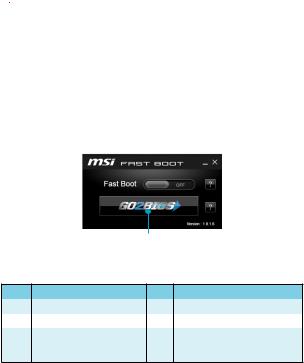
Entering BIOS Setup
Please refer the following methods to enter BIOS setup.
yPress Delete key, when the Press DEL key to enter Setup Menu, F11 to enter Boot Menu message appears on the screen during the boot process.
yUse MSI FAST BOOT application. Click on GO2BIOS button and choose OK. The system will reboot and enter BIOS setup directly.
Click on GO2BIOS
Function key
Key |
Function |
Key |
Function |
|
|
|
|
F1 |
General Help |
F4 |
Enter CPU Specifications menu |
F5 |
Enter Memory-Z menu |
F6 |
Load optimized defaults |
|
|
|
|
|
|
|
Take a screenshot and save it |
F10 |
Save Change and Reset* |
F12 |
to USB flash drive (FAT/ FAT32 |
|
|
|
format only). |
* When you press F10, a confirmation window which provides the modification information appears. Select between Yes or No to confirm your choice.
BIOS Setup 15

Resetting BIOS
You might need to restore the default BIOS setting to solve certain problems. There are several ways to reset BIOS:
yGo to BIOS and press F6 to load optimized defaults.
yShort the Clear CMOS jumper on the motherboard.
 Important
Please refer to the Clear CMOS Jumper section for resetting BIOS.
Updating BIOS
Updating BIOS with M-FLASH
Before updating:
Please download the latest BIOS file that matches your motherboard model from MSI website. And then save the BIOS file into the USB flash drive.
Updating BIOS:
1.Insert the USB flash drive that contains the update file into the computer.
2.Reboot the system, and then press Del key to enter the BIOS Setup during POST.
3.Go to BIOS > M-FLASH > Select one file to update BIOS and ME, select a BIOS file to perform the BIOS update process.
4.After the flashing process is 100% complete, the system will reboot.
Updating the BIOS with Live Update 6
Before updating:
Make sure the LAN driver is already installed and the internet connection is set properly.
Updating BIOS:
1.Install and launch MSI LIVE UPDATE 6.
2.Select Manual scan.
3.Check MB BIOS box and click on Scan button.
4. Select the MB BIOS and click on |
icon to download and install the latest BIOS |
file. |
|
5.Click Next and choose In Windows mode. And then click Next and Start to start updating BIOS.
6.After the flashing process is 100% completed, the system will restart automatically.
16 BIOS Setup
Software Description
Installing Windows® 7/ 8.1/ 10
1.Power on the computer.
2.Insert the Windows® 7/ 8.1/ 10 disc into your optical drive.
Note: Due to chipset limitation, during the Windows® 7 installation process, USB optical drives or USB pen drives are not supported.
3.Press the Restart button on the computer case.
4.For windows 8.1/ 10, skip this step. For Windows 7, access the BIOS menu
Advanced > Windows OS Configuration > Windows 7 Installation and set the item to enabled, save changes and restart.
Note: It is suggested to plug in your USB Keyboard/USB Mouse to the leftmost USB port when installing Windows 7.
5.Press F11 key during the computer POST (Power-On Self Test) to get into Boot Menu.
6.Select your optical drive from the Boot Menu.
7.Press any key when screen shows Press any key to boot from CD or DVD...
message.
8.Follow the instructions on the screen to install Windows® 7/ 8.1/ 10.
Installing Drivers
1.Start up your computer in Windows® 7/ 8.1/ 10.
2.Insert MSI® Driver Disc into your optical drive.
3.The installer will automatically appear and it will find and list all necessary drivers.
4.Click Install button.
5.The software installation will then be in progress, after it has finished it will prompt you to restart.
6.Click OK button to finish.
7.Restart your computer.
Installing Utilities
Before you install utilities, you must complete drivers installation.
1.Insert MSI® Driver Disc into your optical drive.
2.The installer will automatically appear.
3.Click Utilities tab.
4.Select the utilities you want to install.
5.Click Install button.
6.The utilities installation will then be in progress, after it has finished it will prompt you to restart.
7.Click OK button to finish.
8.Restart your computer.
Software Description 17

NOTE
18 NOTE
MSI® H110I PRO ., , BIOS.
|
|
|
|
|
........................................................................................................... |
|
|
|
2 |
................................................................................................................... |
|
|
|
3 |
I/O ..................................................................................................... |
|
|
5 |
|
LAN LED ...................................................................................... |
5 |
|||
................................................................................................................... |
|
|
|
6 |
CPU ............................................................................................................. |
|
7 |
||
DIMM ........................................................................................................... |
|
8 |
||
PCI_E1: PCIe ....................................................................................... |
8 |
|||
SATA1~4: SATA 6Gb/s ............................................................................. |
9 |
|||
JFP1, JFP2: .............................................................................. |
9 |
|||
M2_2: M.2 |
................................................................................................. |
10 |
||
JPWR1~2: |
...................................................................................... |
11 |
||
JUSB1: USB 2.0 ..................................................................................... |
11 |
|||
JUSB2: USB 3.1 Gen1 ............................................................................ |
12 |
|||
JAUD1: |
................................................................................ |
12 |
||
JCOM1: |
............................................................................... |
12 |
||
CPUFAN, SYSFAN1: .......................................................................... |
13 |
|||
JCI1: |
....................................................................................... |
14 |
||
JBAT1: CMOS (Reset BIOS) ........................................................... |
14 |
|||
BIOS ........................................................................................................ |
|
|
|
15 |
BIOS |
.......................................................................................................... |
|
15 |
|
BIOS |
.......................................................................................................... |
|
16 |
|
BIOS |
................................................................................................... |
16 |
||
...............................................................................................® |
|
17 |
||
Windows |
7/ 8.1/ 10 ........................................................................... |
17 |
||
.............................................................................................. |
17 |
|||
.............................................................................................. |
17 |
|||
1
y (ESD).
y . ,.
y .
y (ESD). ESD ,.
y .
y .
y . ,.
y .
y .
y . y .
y PSU PSU.
y . . y .
y , ..
.
..
.
y 60°C (140°F) . .
2
|
|
|
|
|
|
|
|
|
|
|
||
|
|
|
|
® |
|
® |
|
|
|
|
||
6 |
|
Gen Intel® Core™ i3/i5/i7 |
|
|
|
LGA1151 |
|
|||||
CPU |
Intel |
|
Pentium |
|
Celeron |
® |
. |
|||||
|
|
|
|
|
|
|
|
|
|
|
||
|
|
|
|
|
|
|
|
|
||||
|
y Intel® H110 |
|
|
|
|
|
|
|
||||
|
y DDR4 2 , 32GB |
|
|
|||||||||
|
|
DDR4 2133 MHz * |
|
|
|
|
|
|||||
|
y |
|
|
|
|
|
|
|||||
y Intel® Extreme Memory Profile (XMP) |
|
|||||||||||
|
|
* WWW.MSI. |
||||||||||
|
|
COM . |
|
|
||||||||
|
y PCIe 3.0 x16 1 |
|
|
|
|
|
|
|||||
|
y HDMI™ 1 , 4096x2160@24Hz, 2560x1600@60Hz |
|||||||||||
|
|
|
|
|
|
|
|
|
|
|||
|
y DVI-D 1 , 1920x1200@60Hz |
|
||||||||||
|
Intel® H110 |
|
|
|
|
|
|
|
||||
|
y SATA 6Gb/s 4 |
|
|
|
|
|
|
|||||
y M.2 |
1 |
|
|
|
|
|
|
|
||||
|
|
PCIe 2.0x4 , 4.2cm/6cm/8cm M.2 PCIe- |
||||||||||
|
|
SSD |
|
|
|
|
|
|||||
|
y Intel® H110 |
|
|
|
|
|
|
|
||||
|
|
USB 3.1 Gen1 (SuperSpeed USB) 4 ( 2 |
||||||||||
USB |
|
, USB 2 ) |
|
|
||||||||
|
|
USB 2.0 (High-speed USB) 6 ( 4 , |
||||||||||
|
|
USB |
2 ) |
|
|
|||||||
|
y 7.1- HD |
|
|
|
|
|
|
|
||||
|
y Realtek® ALC887 |
|
|
|
|
|
||||||
LAN |
Realtek® RTL8111H Gigabit LAN 1 |
|
||||||||||
|
y PS/2 / 1 |
|
|
|
||||||||
|
y USB 2.0 4 |
|
|
|
|
|
|
|
||||
|
y DVI-D |
1 |
|
|
|
|
|
|
|
|||
y USB 3.1 Gen1 2 |
|
|
|
|
|
|||||||
|
y HDMI™ 1 |
|
|
|
|
|
|
|
||||
|
y LAN (RJ45) |
1 |
|
|
|
|
|
|
||||
|
y |
3 |
|
|
|
|
|
|
|
|||
|
|
|
|
|
|
|
|
|
||||
3

y 24 ATX 1 y 4 ATX 12V 1 y SATA 6Gb/s 4
y USB 2.0 1 ( USB 2.0 2 )
y USB 3.1 Gen1 1 ( USB 3.1 Gen1 2 )
y 4- CPU 1 y 4- 1
y 1 y 2
y 1 y 1 y CMOS 1
I/O NUVOTON NCT5563
yCPU/y CPU/
yCPU/
|
|
|
y Mini-ITX |
y 6.7 in. x 6.7 in. (17.0 cm x 17.0 cm) |
|
BIOS |
y 64 Mb 1 |
y UEFI AMI BIOS |
|
y ACPI 5.0, PnP 1.0a, SM BIOS 2.8 |
|
|
y |
|
y |
|
y COMMAND CENTER |
|
y LIVE UPDATE 6 |
|
y FAST BOOT |
|
y SUPER CHARGER |
|
y M-CLOUD |
y RAMDISK |
|
|
y Intel® Small Business Basics |
|
y Network Genie |
|
y ® |
|
y Norton™ |
|
y Google Chrome™,Google Toolbar, Google Drive |
|
y CPU-Z |
4
I/O
PS/2 |
|
|
|
|
USB 3.1 Gen1 |
|
|
|
|
|
|
|
|
|
LAN |
USB 2.0 |
DVI-D |
|
USB 2.0 |
LAN LED
/ LED
|
|
|
|
|
LAN |
. |
|
|
LAN |
. |
|
|
LAN |
. |
LED
|
|
|
|
|
10 Mbps |
. |
|
|
100 Mbps |
. |
|
|
1 Gbps |
. |
7.1
7.1 I/O JAUD1 ..
1.Realtek HD Audio Manager > Advanced Settings( ).
2.[Mute the rear output device, when a front headphone plugged in]() .
3.I/O ..
I/O 5
|
CPU |
|
|
||
JPWR2 |
|
|
CPUFAN |
|
DIMM1 |
|
|
|
|||
|
|
SYSFAN1 |
|
||
|
|
|
|
||
DIMM2
JPWR1
|
JFP2 |
|
JFP1 |
JCOM1 |
SATA1 |
JUSB1 |
SATA2 |
|
|
|
SATA3 |
JAUD1 |
JUSB2 |
|
|
JBAT1 |
SATA4 |
|
JCI1 PCI_E1
M2_2
6

CPU
CPU CPU .
2
1
3


 8 7
8 7 


5
 4 6
4 6


9

yCPU .
y, CPU . CPUMSI (RMA) .
yCPU , CPU . CPU.
yCPU .
yCPU CPU. CPU( ) .
yCPU , CPU.
yCPU / , /.
7
DIMM
DIMM .
2
1 |
2 |
3 |

y .
y 4GB 32- (Windows OS). 4GB 64Windows OS .
PCI_E1: PCIe
PCI_E1: PCIe 3.0 x16

..
8
SATA1~4: SATA 6Gb/s
SATA 6Gb/s . SATA.
|
SATA1 |
SATA3 |
SATA2 |
|
|
SATA4 |
|

ySATA 90 . , .
ySATA .
JFP1, JFP2:
LED .
|
|
1 |
HDD LED + |
2 |
Power LED + |
10 |
9 |
3 |
HDD LED - |
4 |
Power LED - |
JFP1 |
|
5 |
Reset Switch |
6 |
Power Switch |
2 |
1 |
7 |
Reset Switch |
8 |
Power Switch |
|
|
9 |
Reserved |
10 |
No Pin |
HDDLED |
RESETSW |
|
JFP1 |
|
1 |
JFP2 |
|
1 |
3 |
|
HDD LED |
|
|
|
|
|
HDD LED - |
|
|
|
|
|
|
|
HDD LED + |
|
|
|
|
|
|
|
POWER LED - |
|
POWER LED |
|
|
|
|
|
POWER LED + |
|
|
|
|
|
|
|
Speaker - |
2 |
Buzzer + |
Buzzer - |
4 |
Speaker + |
|
|
|
9
M2_2: M.2

M.2 . http://youtu.be/JCTFABytrYA
M.2
1. |
. |
|
2. |
. |
1 |
|
|
2 |
3. M.2 .
4. 30 M.2 M.2
.
3


4 |
30° 
5. M.2 |
|
|
5 |
|
|
. |
|

M.2.
10
JPWR1~2:
ATX .
|
|
|
|
|
|
|
1 |
+3.3V |
13 |
+3.3V |
|
|
|
|
|
|
|
|
|
|
|
|
|
|
|
|
|
|
2 |
+3.3V |
14 |
-12V |
12 |
|
|
|
24 |
|
|
3 |
Ground |
15 |
Ground |
|
|
|
|
|
|
|
|
|
||
|
|
4 |
+5V |
16 |
PS-ON# |
|||||
|
|
|
|
|
|
|
||||
|
|
|
|
|
|
|
|
|
|
|
|
|
|
|
|
|
|
5 |
Ground |
17 |
Ground |
|
|
|
|
|
JPWR1 |
6 |
+5V |
18 |
Ground |
|
|
|
|
|
|
|
|
7 |
Ground |
19 |
Ground |
|
|
|
|
|
|
|
8 |
PWR OK |
20 |
Res |
|
|
|
|
|
|
|
|
|
|
|
1 |
|
|
|
13 |
|
|
9 |
5VSB |
21 |
+5V |
|
|
|
|
|
|
|
|
|
||
|
|
10 |
+12V |
22 |
+5V |
|||||
|
|
|
|
|
|
|
||||
|
|
|
|
|
|
|
11 |
+12V |
23 |
+5V |
|
|
|
|
|
|
|
|
|
|
|
|
|
|
|
|
|
|
12 |
+3.3V |
24 |
Ground |
|
|
|
|
|
|
|
|
|
|
|
3 |
|
|
|
1 |
JPWR2 |
1 |
Ground |
3 |
+12V |
|
4 |
|
|
|
2 |
|
2 |
Ground |
4 |
+12V |
|
|
|
|
|
|
|
|||||

ATX.
JUSB1: USB 2.0
USB 2.0 .
|
|
|
|
|
|
|
1 |
VCC |
2 |
VCC |
|
|
|
|
|
|
|
|
|
|
|
|
2 |
10 |
|
3 |
USB0- |
4 |
USB1- |
|||
|
|
|
|
|
|
|
5 |
USB0+ |
6 |
USB1+ |
|
|
|
|
|
|
|
|
|
|
|
|
1 |
9 |
|
7 |
Ground |
8 |
Ground |
|||
|
|
|
|
|
|
|
9 |
No Pin |
10 |
NC |

yVCC .
yUSB iPad, iPhone iPod MSI® SUPER CHARGER
.
11

JUSB2: USB 3.1 Gen1
USB 3.1 Gen1 .
|
|
|
1 |
Power |
11 |
USB2.0+ |
|
|
|
|
|
|
|
|
|
|
2 |
USB3_RX_DN |
12 |
USB2.0- |
10 |
|
11 |
3 |
USB3_RX_DP |
13 |
Ground |
|
||||||
|
|
|
|
|
||
|
|
|
4 |
Ground |
14 |
USB3_TX_C_DP |
|
|
|
5 |
USB3_TX_C_DN |
15 |
USB3_TX_C_DN |
|
|
|
||||
|
|
|
|
|
|
|
|
|
|
6 |
USB3_TX_C_DP |
16 |
Ground |
|
|
|
||||
|
|
|
|
|
|
|
|
|
|
7 |
Ground |
17 |
USB3_RX_DP |
1 |
|
20 |
8 |
USB2.0- |
18 |
USB3_RX_DN |
|
|
|
9 |
USB2.0+ |
19 |
Power |
|
|
|
10 |
Ground |
20 |
No Pin |

.
JAUD1:
.
|
|
|
|
|
|
|
1 |
MIC L |
2 |
Ground |
|
|
|
|
|
|
|
|
|
|
|
2 |
10 |
|
3 |
MIC R |
4 |
NC |
||||
|
|
|
|
|
|
|
5 |
Head Phone R |
6 |
MIC Detection |
1 |
9 |
|
7 |
SENSE_SEND |
8 |
No Pin |
||||
|
|
|
|
|
|
|
|
|
|
|
|
|
|
|
|
|
|
9 |
Head Phone L |
10 |
Head Phone Detection |
JCOM1:
.
|
|
|
|
|
|
|
1 |
DCD |
2 |
SIN |
|
|
|
|
|
|
|
|
|
|
|
2 |
10 |
|
3 |
SOUT |
4 |
DTR |
||||
|
|
|
|
|
|
|
5 |
Ground |
6 |
DSR |
|
|
|
|
|
|
|
|
|
|
|
1 |
9 |
|
7 |
RTS |
8 |
CTS |
||||
|
|
|
|
|
|
|
|
|
|
|
|
|
|
|
|
|
|
9 |
RI |
10 |
No Pin |
12
 Loading...