


 Loading...
PROFESSIONAL DIGITAL TWO-WAY RADIO
MOTOTRBO™
XPR™ 7550
COLOR DISPLAY PORTABLE
USER GUIDE

Declaration of Conformity
This declaration is applicable to your radio only if your radio is labeled with the FCC logo shown below.
DECLARATION OF CONFORMITY
Per FCC CFR 47 Part 2 Section 2.1077(a)
Responsible Party
Name: Motorola Solutions, Inc.
Address: 1303 East Algonquin Road, Schaumburg, IL 60196-1078, U.S.A. Phone Number: 1-800-927-2744
Hereby declares that the product: Model Name: XPR 7550
conforms to the following regulations:
FCC Part 15, subpart B, section 15.107(a), 15.107(d) and section 15.109(a)
Class B Digital Device
As a personal computer peripheral, this device complies with Part 15 of the FCC Rules. This device complies with Industry Canada licence-exempt RSS standard(s). Operation is subject to the following two conditions:
1.This device may not cause harmful interference, and
2.This device must accept any interference received, including interference that may cause undesired operation.
Conformity of Declaration
i
English

Declaration of Conformity
ii
Note: This equipment has been tested and found to comply with the limits for a Class B digital device, pursuant to part 15 of the FCC Rules. These limits are designed to provide reasonable protection against harmful interference in a residential installation. This equipment generates, uses and can radiate radio frequency energy and, if not installed and used in accordance with the instructions, may cause harmful interference to radio communications. However, there is no guarantee that interference will not occur in a particular installation.
If this equipment does cause harmful interference to radio or television reception, which can be determined by turning the equipment off and on, the user is encouraged to try to correct the interference by one or more of the following measures:
•Reorient or relocate the receiving antenna.
•Increase the separation between the equipment and receiver.
•Connect the equipment into an outlet on a circuit different from that to which the receiver is connected.
•Consult the dealer or an experienced radio/TV technician for help.
English

Contents
This User Guide contains all the information you need to use the MOTOTRBO XPR Series Digital Portable Radios.
Declaration of Conformity . . . . . . . . . . . . . . . . . . . . . i
Important Safety Information . . . . . . . . . . . . . . . . viii
Product Safety and RF Exposure Compliance . .viii
Software Version . . . . . . . . . . . . . . . . . . . . . . . . . . viii Computer Software Copyrights . . . . . . . . . . . . . . . ix Handling Precautions . . . . . . . . . . . . . . . . . . . . . . . . x
Getting Started . . . . . . . . . . . . . . . . . . . . . . . . . . . . . . 1
How to Use This Guide . . . . . . . . . . . . . . . . . . . . . . . 1 What Your Dealer/System Administrator
Can Tell You . . . . . . . . . . . . . . . . . . . . . . . . . . . . . . 1
Preparing Your Radio for Use . . . . . . . . . . . . . . . . . . 2
Charging the Battery . . . . . . . . . . . . . . . . . . . . . . . . . 2 Attaching the Battery . . . . . . . . . . . . . . . . . . . . . . . . . 3 Attaching the Antenna . . . . . . . . . . . . . . . . . . . . . . . . 3 Attaching the Belt Clip . . . . . . . . . . . . . . . . . . . . . . . . 4 Attaching the Universal Connector Cover (Dust Cover)
. . . . . . . . . . . . . . . . . . . . . . . . . . . . . . . . . . . . . . . . . . 4 Powering Up the Radio . . . . . . . . . . . . . . . . . . . . . . . 5 Adjusting the Volume . . . . . . . . . . . . . . . . . . . . . . . . 6
Identifying Radio Controls . . . . . . . . . . . . . . . . . . . . 6
Radio Controls . . . . . . . . . . . . . . . . . . . . . . . . . . . . . 7 Programmable Buttons . . . . . . . . . . . . . . . . . . . . . . . 8 Assignable Radio Functions . . . . . . . . . . . . . . . . . 8 Assignable Settings or Utility Functions . . . . . . . . . 9 Using the 4-Way Navigation Button . . . . . . . . . . . . 10 Accessing the Programmed Functions . . . . . . . . . . 10 Using the Keypad . . . . . . . . . . . . . . . . . . . . . . . . . . 11 Push-To-Talk (PTT) Button . . . . . . . . . . . . . . . . . . . 12 Switching Between Conventional Analog and Digital Mode . . . . . . . . . . . . . . . . . . . . . . . . . . . . . . . . . . . 13 IP Site Connect . . . . . . . . . . . . . . . . . . . . . . . . . . . 13 Capacity Plus . . . . . . . . . . . . . . . . . . . . . . . . . . . . . 14 Linked Capacity Plus . . . . . . . . . . . . . . . . . . . . . . . 14
Identifying Status Indicators . . . . . . . . . . . . . . . . . . 15
Display Icons . . . . . . . . . . . . . . . . . . . . . . . . . . . . . . 16 Call Icons . . . . . . . . . . . . . . . . . . . . . . . . . . . . . . . . 17 Advanced Menu Icons . . . . . . . . . . . . . . . . . . . . . . 18 Mini Notice Icons . . . . . . . . . . . . . . . . . . . . . . . . . . . 18 Sent Item Icons . . . . . . . . . . . . . . . . . . . . . . . . . . . 19 Bluetooth Device Icons . . . . . . . . . . . . . . . . . . . . . . 19 LED Indicator . . . . . . . . . . . . . . . . . . . . . . . . . . . . . 20 Indicator Tones . . . . . . . . . . . . . . . . . . . . . . . . . . . . 21 Audio Tones . . . . . . . . . . . . . . . . . . . . . . . . . . . . . . 21
Contents
iii
English

Contents
iv
Making and Receiving Calls . . . . . . . . . . . . . . . . . . 22
Selecting a Zone . . . . . . . . . . . . . . . . . . . . . . . . . . 22 Selecting a Channel . . . . . . . . . . . . . . . . . . . . . . . . 23 Receiving and Responding to a Radio Call . . . . . . 24 Receiving and Responding to a Group Call . . . . 24 Receiving and Responding to a Private Call . . . 25 Receiving an All Call . . . . . . . . . . . . . . . . . . . . . . 25 Receiving and Responding to a Selective Call . . 26 Making a Radio Call . . . . . . . . . . . . . . . . . . . . . . . . 27
Making a Call with the Channel Selector Knob . . |
27 |
Making a Group Call . . . . . . . . . . . . . . . . . . . . |
27 |
Making a Private Call . . . . . . . . . . . . . . . . . . . |
28 |
Making an All Call . . . . . . . . . . . . . . . . . . . . . . |
29 |
Making a Selective Call . . . . . . . . . . . . . . . . . |
29 |
Making a Group, Private or All Call with the |
|
Programmable Number Key . . . . . . . . . . . . . . . |
30 |
Stopping a Radio Call . . . . . . . . . . . . . . . . . . . . . . |
31 |
Talkaround . . . . . . . . . . . . . . . . . . . . . . . . . . . . . . . 32
Monitoring Features . . . . . . . . . . . . . . . . . . . . . . . . 33
Monitoring a Channel . . . . . . . . . . . . . . . . . . . . . 33
Permanent Monitor . . . . . . . . . . . . . . . . . . . . . . . 33
Advanced Features . . . . . . . . . . . . . . . . . . . . . . . . . 34
Radio Check . . . . . . . . . . . . . . . . . . . . . . . . . . . . . 35
Sending a Radio Check . . . . . . . . . . . . . . . . . . . 35
Remote Monitor . . . . . . . . . . . . . . . . . . . . . . . . . . . 36
Initiating Remote Monitor . . . . . . . . . . . . . . . . |
. . 36 |
Stopping Remote Monitor . . . . . . . . . . . . . . . . |
. . 37 |
Scan Lists . . . . . . . . . . . . . . . . . . . . . . . . . . . . . . |
. . 38 |
Viewing an Entry in the Scan List . . . . . . . . . . |
. . 38 |
Viewing an Entry in the Scan List by Alias Search 38 |
|
Editing the Scan List . . . . . . . . . . . . . . . . . . . . |
. . 39 |
Adding a New Entry to the Scan List . . . . . . |
. . 39 |
Deleting an Entry from the Scan List . . . . . . . |
. 39 |
Setting and Editing Priority for an Entry in the Scan |
|
List . . . . . . . . . . . . . . . . . . . . . . . . . . . . . . . . . |
. 40 |
Scan . . . . . . . . . . . . . . . . . . . . . . . . . . . . . . . . . . . |
. 41 |
Starting and Stopping Scan . . . . . . . . . . . . . . . |
. 42 |
Responding to a Transmission During a Scan |
. . 42 |
Deleting a Nuisance Channel . . . . . . . . . . . . . . |
. 43 |
Restoring a Nuisance Channel . . . . . . . . . . . . . |
. 43 |
Vote Scan . . . . . . . . . . . . . . . . . . . . . . . . . . . . . . . |
. 43 |
Contacts Settings . . . . . . . . . . . . . . . . . . . . . . . . . |
. 44 |
Making a Group Call from Contacts . . . . . . . . . |
. 44 |
Making a Private Call from Contacts . . . . . . . . |
. 45 |
Making a Call by Alias Search . . . . . . . . . . . . . |
. 46 |
Assigning an Entry to a Programmable |
|
Number Key . . . . . . . . . . . . . . . . . . . . . . . . . . . |
. 47 |
Removing the Association between Entry and |
|
Programmable Number Key . . . . . . . . . . . . . . |
. 47 |
Setting Default Contact . . . . . . . . . . . . . . . . . . |
. 48 |
Call Indicator Settings . . . . . . . . . . . . . . . . . . . . . |
. 48 |
English

Activating or Deactivating Call Ringers for Call Alert |
|
. . . . . . . . . . . . . . . . . . . . . . . . . . . . . . . . . . . . . . . |
48 |
Activating or Deactivating Call Ringers for Private |
|
Calls . . . . . . . . . . . . . . . . . . . . . . . . . . . . . . . . . . |
49 |
Activating or Deactivating Call Ringers for Selective |
|
Call . . . . . . . . . . . . . . . . . . . . . . . . . . . . . . . . . . . |
49 |
Activating or Deactivating Call Ringers for Text |
|
Message . . . . . . . . . . . . . . . . . . . . . . . . . . . . . . . |
50 |
Activating or Deactivating Call Ringers for Telemetry |
|
Status with Text . . . . . . . . . . . . . . . . . . . . . . . . . |
50 |
Assigning Ring Styles . . . . . . . . . . . . . . . . . . . . . |
51 |
Escalating Alarm Tone Volume . . . . . . . . . . . . . . |
51 |
Call Log Features . . . . . . . . . . . . . . . . . . . . . . . . . . |
52 |
Viewing Recent Calls . . . . . . . . . . . . . . . . . . . . . . |
52 |
Storing an Alias or ID from a Call List . . . . . . . . . |
52 |
Deleting a Call from a Call List . . . . . . . . . . . . . . |
52 |
Viewing Details from a Call List . . . . . . . . . . . . . . |
53 |
Call Alert Operation . . . . . . . . . . . . . . . . . . . . . . . . . |
53 |
Receiving and Responding to a Call Alert . . . . . . |
53 |
Making a Call Alert from the Contacts List . . . . . . |
54 |
Making a Call Alert with the One Touch Access Button |
|
. . . . . . . . . . . . . . . . . . . . . . . . . . . . . . . . . . . . . . . |
54 |
Emergency Operation . . . . . . . . . . . . . . . . . . . . . . . |
55 |
Receiving an Emergency Alarm . . . . . . . . . . . . . |
55 |
Responding to an Emergency Alarm . . . . . . . . . . |
56 |
Sending an Emergency Alarm . . . . . . . . . . . . . . . |
56 |
Sending an Emergency Alarm with Call . . . . . . . 57 Sending an Emergency Alarm with Voice to Follow
. . . . . . . . . . . . . . . . . . . . . . . . . . . . . . . . . . . . . . . 58 Reinitiating an Emergency Mode . . . . . . . . . . . . . 59 Exiting Emergency Mode . . . . . . . . . . . . . . . . . . . 59 Text Message Features . . . . . . . . . . . . . . . . . . . . . 60 Writing and Sending a Text Message . . . . . . . . . 60 Sending a Quick Text Message . . . . . . . . . . . . . . 61 Sending a Quick Text Message with the One Touch Access Button . . . . . . . . . . . . . . . . . . . . . . . . . . . 62 Accessing the Drafts Folder . . . . . . . . . . . . . . . . . 62 Viewing a Saved Text Message . . . . . . . . . . . . 62 Editing and Sending a Saved Text Message . . 62 Deleting a Saved Text Message from Drafts . . 63 Managing Fail-to-Send Text Messages . . . . . . . . 63 Resending a Text Message . . . . . . . . . . . . . . . 64 Forwarding a Text Message . . . . . . . . . . . . . . . 64 Editing a Text Message . . . . . . . . . . . . . . . . . . 64 Managing Sent Text Messages . . . . . . . . . . . . . . 65 Viewing a Sent Text Message . . . . . . . . . . . . . 65 Sending a Sent Text Message . . . . . . . . . . . . . 65 Deleting All Sent Text Messages from Sent Items
. . . . . . . . . . . . . . . . . . . . . . . . . . . . . . . . . . . . . 67 Receiving a Text Message . . . . . . . . . . . . . . . . . 67 Reading a Text Message . . . . . . . . . . . . . . . . . . . 67 Managing Received Text Messages . . . . . . . . . . 68
Contents
v
English

Contents
vi
Viewing a Text Message from the Inbox . . . . . 68 Viewing a Telemetry Status Text Message from the Inbox . . . . . . . . . . . . . . . . . . . . . . . . . . . . . . . . 68 Replying to a Text Message from the Inbox . . 69 Deleting a Text Message from the Inbox . . . . . 69 Deleting All Text Messages from the Inbox . . . 70
Analog Message Encode . . . . . . . . . . . . . . . . . . . 71 Sending MDC Message Encode to Dispatcher . . 71 Analog Status Update . . . . . . . . . . . . . . . . . . . . . . 71 Sending Status Update to Predefined Contact . . 71 Privacy . . . . . . . . . . . . . . . . . . . . . . . . . . . . . . . . . . 72 Dual Tone Multi Frequency (DTMF) . . . . . . . . . . . . 73 Multi-Site Controls . . . . . . . . . . . . . . . . . . . . . . . . . 74 Starting an Automatic Site Search . . . . . . . . . . . 74 Stopping an Automatic Site Search . . . . . . . . . . 74 Starting a Manual Site Search . . . . . . . . . . . . . . 75 Security . . . . . . . . . . . . . . . . . . . . . . . . . . . . . . . . . 76 Radio Disable . . . . . . . . . . . . . . . . . . . . . . . . . . . 76 Radio Enable . . . . . . . . . . . . . . . . . . . . . . . . . . . 77 Lone Worker . . . . . . . . . . . . . . . . . . . . . . . . . . . . . . 78 Password Lock Features . . . . . . . . . . . . . . . . . . . . 78 Accessing the Radio from Password . . . . . . . . . 78 Unlocking the Radio from Locked State . . . . . . . 79 Turning the Password Lock On or Off . . . . . . . . . 79 Changing the Password . . . . . . . . . . . . . . . . . . . 80 Bluetooth Operation . . . . . . . . . . . . . . . . . . . . . . . . 81
Finding and Connecting to a Bluetooth Device . |
. 81 |
|
Disconnecting from a Bluetooth Device . . |
. . . . |
. 82 |
Switching Audio Route . . . . . . . . . . . . . . . |
. . . . . |
82 |
Viewing Device Details . . . . . . . . . . . . . . . |
. . . . . |
83 |
Editing Device Name . . . . . . . . . . . . . . . . |
. . . . . |
83 |
Notification List . . . . . . . . . . . . . . . . . . . . . . . |
. . . . . |
84 |
Accessing the Notification List . . . . . . . . . . |
. . . . |
84 |
Utilities . . . . . . . . . . . . . . . . . . . . . . . . . . . . . . |
. . . . |
84 |
Turning the Radio Tones/Alerts On or Off |
. . . . . 84 |
|
Turning Keypad Tones On or Off . . . . . . . . |
. . . . |
85 |
Setting the Tone Alert Volume Offset Level |
. . . . 85 |
|
Turning the Talk Permit Tone On or Off . . . |
. . . . |
86 |
Setting the Power Level . . . . . . . . . . . . . . . |
. . . . |
86 |
Changing the Display Mode . . . . . . . . . . . . |
. . . . |
87 |
Adjusting the Display Brightness . . . . . . . . |
. . . . |
87 |
Controlling the Display Backlight . . . . . . . . |
. . . . |
87 |
Setting the Squelch Level . . . . . . . . . . . . . |
. . . . |
88 |
Turning the Introduction Screen On or Off |
. . . . . 88 |
|
Locking and Unlocking the Keypad . . . . . . . |
. . . . |
89 |
Language . . . . . . . . . . . . . . . . . . . . . . . . . . |
. . . . |
89 |
Turning the LED Indicator On or Off . . . . . . |
. . . . |
90 |
Turning the Voice Operating Transmission (VOX) |
||
Feature On or Off . . . . . . . . . . . . . . . . . . . . |
. . . . |
90 |
Turning the Option Board Feature(s) On or Off |
. 91 |
|
Identifying Cable Type . . . . . . . . . . . . . . . . |
. . . . |
91 |
English

Voice Announcement . . . . . . . . . . . . . . . . . . . . . . 91 Call Forwarding . . . . . . . . . . . . . . . . . . . . . . . . . . 92 Menu Timer . . . . . . . . . . . . . . . . . . . . . . . . . . . . . 92 Analog Mic AGC . . . . . . . . . . . . . . . . . . . . . . . . . 92 Digital Mic AGC . . . . . . . . . . . . . . . . . . . . . . . . . . 93 Intelligent Audio . . . . . . . . . . . . . . . . . . . . . . . . . . 93 GPS . . . . . . . . . . . . . . . . . . . . . . . . . . . . . . . . . . . 94 Accessing General Radio Information . . . . . . . . . 94
Accessing the Battery Information . . . . . . . . . . 95 Checking the Radio Alias and ID . . . . . . . . . . . 95 Checking the Firmware Version and Codeplug Version . . . . . . . . . . . . . . . . . . . . . . . . . . . . . . . . . . 95 Checking the GPS Information . . . . . . . . . . . . . 96
Front Panel Configuration (FPC) . . . . . . . . . . . . . . |
97 |
Entering FPC Mode . . . . . . . . . . . . . . . . . . . . . . . 97
Editing FPC Mode Parameters . . . . . . . . . . . . . . 97
Accessories . . . . . . . . . . . . . . . . . . . . . . . . . . . . . . . 98
Antennas . . . . . . . . . . . . . . . . . . . . . . . . . . . . . . . . . 98
Batteries . . . . . . . . . . . . . . . . . . . . . . . . . . . . . . . . . 98
Carry Devices . . . . . . . . . . . . . . . . . . . . . . . . . . . . . 99
Chargers . . . . . . . . . . . . . . . . . . . . . . . . . . . . . . . . . 99
Headsets and Headset Accessories . . . . . . . . . . . . 99
Earbuds and Earpieces . . . . . . . . . . . . . . . . . . . . . 100
Remote Speaker Microphones . . . . . . . . . . . . . . . 100
Surveillance Accessories . . . . . . . . . . . . . . . . . . . 100
Miscellaneous Accessories . . . . . . . . . . . . . . . . . . 101
Batteries and Chargers Warranty . . . . . . . . . . . . . 102
Limited Warranty . . . . . . . . . . . . . . . . . . . . . . . . . . 103
Notes . . . . . . . . . . . . . . . . . . . . . . . . . . . . . . . . . . . . 106
Contents
vii
English

Important Safety Information
viii
Important Safety Information
Product Safety and RF Exposure Compliance
Before using this product, read the operating instructions for safe usage contained in the Product Safety and RF Exposure booklet enclosed with your radio.
ATTENTION!
This radio is restricted to occupational use only to satisfy FCC RF energy exposure requirements.
Before using this product, read the RF energy awareness information and operating instructions in the Regulatory Compliance and Product Safety section of your Quick Reference Guide enclosed with your radio (Motorola Publication part number 68009503001) to ensure compliance with RF energy exposure limits.
For a list of Motorola-approved antennas, batteries, and other accessories, visit the following website:
http://www.motorolasolutions.com/governmentandenterprise
Any modification to this device, not expressly authorized by Motorola, may void the user’s authority to operate this device.
Under Industry Canada regulations, this radio transmitter may only operate using an antenna of a type and maximum (or lesser) gain approved for the transmitter by Industry Canada. To reduce potential radio interference to other users, the antenna type and its gain should be so chosen that the equivalent isotropically radiated power (e.i.r.p.) is not more than that necessary for successful communication.
Software Version
All the features described in the following sections are supported by the radio's software version R02.04.00.
See Checking the Firmware Version and Codeplug Version on page 95 to determine your radio's software version.
Check with your dealer or system administrator for more details of all the features supported.
English
Computer Software Copyrights
The Motorola products described in this manual may include copyrighted Motorola computer programs stored in semiconductor memories or other media. Laws in the United States and other countries preserve for Motorola certain exclusive rights for copyrighted computer programs including, but not limited to, the exclusive right to copy or reproduce in any form the copyrighted computer program. Accordingly, any copyrighted Motorola computer programs contained in the Motorola products described in this manual may not be copied, reproduced, modified, reverse-engineered, or distributed in any manner without the express written permission of Motorola. Furthermore, the purchase of Motorola products shall not be deemed to grant either directly or by implication, estoppel, or otherwise, any license under the copyrights, patents or patent applications of Motorola, except for the normal non-exclusive license to use that arises by operation of law in the sale of a product.
The AMBE+2TM voice coding Technology embodied in this product is protected by intellectual property rights including patent rights, copyrights and trade secrets of Digital Voice Systems, Inc.
This voice coding Technology is licensed solely for use within this Communications Equipment. The user of this Technology is explicitly prohibited from attempting to decompile, reverse engineer, or disassemble the Object Code, or in any other way convert the Object Code into a human-readable form.
U.S. Pat. Nos. #5,870,405, #5,826,222, #5,754,974, #5,701,390, #5,715,365, #5,649,050, #5,630,011, #5,581,656, #5,517,511, #5,491,772, #5,247,579, #5,226,084 and #5,195,166.
Copyrights Software Computer
ix
English

Handling Precautions
x
Handling Precautions
The MOTOTRBO Series Digital Portable radio meets IP57 specifications, allowing the radio to withstand adverse field conditions such as being submersed in water.
•If the radio has been submersed in water, shake the radio well to remove any water that may be trapped inside the speaker grille and microphone port. Trapped water could cause decreased audio performance.
•If the radio’s battery contact area has been exposed to water, clean and dry battery contacts on both the radio and the battery before attaching the battery to the radio. The residual water could short-circuit the radio.
•If the radio has been submersed in a corrosive substance (e.g. saltwater), rinse the radio and battery in fresh water then dry the radio and battery.
•To clean the exterior surfaces of the radio, use a diluted solution of mild dishwashing detergent and fresh water (i.e. one teaspoon of detergent to one gallon of water).
•Never poke the vent (hole) located on the radio chassis below the battery contact. This vent allows for pressure equalization in the radio. Doing so may create a leak path into the radio and the radio’s submersibility may be lost.
•Never obstruct or cover the vent, even with a label.
•Ensure that no oily substances come in contact with the vent.
•The radio with antenna attached properly is designed to be submersible to a maximum depth of 1 meter (3.28 feet) and a maximum submersion time of 30 minutes. Exceeding either maximum limit or use without antenna may result in damage to the radio.
•When cleaning the radio, do not use a high pressure jet spray on the radio as this will exceed the 1 meter depth pressure and may cause water to leak into the radio.
Do not disassemble the radio. This could damage radio seals and result in leak paths into the radio. Radio maintenance should only be done in service depot that is equipped to test and replace the seal on the radio.
English

Getting Started
Take a moment to review the following:
How to Use This Guide . . . . . . . . . . . . . . . . . . . . . . . . . page 1
What Your Dealer/System Administrator
Can Tell You. . . . . . . . . . . . . . . . . . . . . . . . . . . . . . . . page 1
 How to Use This Guide
This User Guide covers the basic operation of the MOTOTRBO Portables.
However, your dealer or system administrator may have customized your radio for your specific needs. Check with your dealer or system administrator for more information.
Throughout this publication, the icons below are used to indicate features supported in either the conventional Analog mode or conventional Digital mode:
Indicates a conventional Analog Mode-Only feature.
Indicates a conventional Digital Mode-Only feature.
For features that are available in both conventional Analog and Digital modes, no icon is shown.
For features that are available in a conventional multi-site mode, see IP Site Connect on page 13 for more information.
Selected features are also available on the single-site trunking mode, Capacity Plus. See Capacity Plus on page 14 for more information.
Selected features are also available in the multi-site trunking mode, Linked Capacity Plus. See Linked Capacity Plus on page 14 for more information.
 What Your Dealer/System Administrator
Can Tell You
You can consult your dealer or system administrator about the following:
•Is your radio programmed with any preset conventional channels?
•Which buttons have been programmed to access other features?
•What optional accessories may suit your needs?
•What are the best radio usage practices for effective communication?
•What maintenance procedures will help promote longer radio life?
Started Getting
1
English

Preparing Your Radio for Use
2
Preparing Your Radio for Use
Assemble your radio by following these steps:
Charging the Battery . . . . . . . . . . . . . . . . . . . . . . . . . . . page 2 Attaching the Battery. . . . . . . . . . . . . . . . . . . . . . . . . . . page 3 Attaching the Antenna. . . . . . . . . . . . . . . . . . . . . . . . . . page 3 Attaching the Belt Clip. . . . . . . . . . . . . . . . . . . . . . . . . . page 4
Attaching the Universal Connector
Cover (Dust Cover) . . . . . . . . . . . . . . . . . . . . . . . . . . page 4 Powering Up the Radio . . . . . . . . . . . . . . . . . . . . . . . . . page 5 Adjusting the Volume . . . . . . . . . . . . . . . . . . . . . . . . . . page 6
 Charging the Battery
For best performance, your radio is powered by a Motorola-approved Nickel Metal-Hydride (NiMH) or Lithium-Ion (Li-lon) battery. To avoid damage and comply with warranty terms, charge the battery using a Motorola charger exactly as described in the charger user guide.
Charge a new battery 14 to 16 hours before initial use for best performance.
IMPORTANT: ALWAYS charge your IMPRES battery with an IMPRES charger for optimized battery life and valuable battery data. IMPRES batteries charged exclusively with IMPRES chargers receive a 6-month capacity warranty extension over the standard Motorola Premium battery warranty duration.
English

 Attaching the Battery
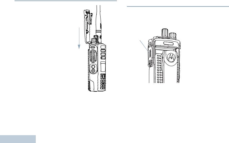
Align the battery with the rails on the back of the radio. Press the battery firmly, and slide upward until the latch snaps into place. Slide battery latch into lock position.
To remove the battery, turn the radio off. Move the battery latch into unlock position and hold, and slide the battery down
and off the rails.
Battery Latch
 Attaching the Antenna
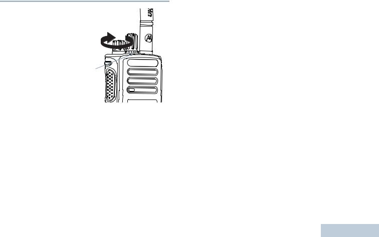
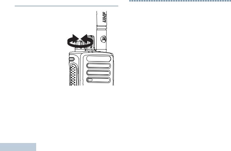
With the radio turned off, set the antenna in its receptacle and turn clockwise.
To remove the antenna, turn the antenna counterclockwise.
If antenna needs to be replaced, ensure that only MOTOTRBO antennas are used. Neglecting this will damage your radio. See Antennas on page 98 for a list of available antennas.
Use for Radio Your Preparing
3
English

 Attaching the Belt Clip
Align the grooves on the clip with those on the battery and press downward until you hear a click.
Use |
To remove the clip, press the |
|
belt clip tab away from the |
||
|
||
for |
battery. Using a key may be |
|
helpful. Then slide the clip |
||
|
||
RadioYourPreparing |
upward and away from the |
|
radio. |
||
|
||
4 |
|
 Attaching the Universal Connector Cover
(Dust Cover)
The universal connector is located on the antenna side of the radio. It is used to connect MOTOTRBO accessories to the radio.
|
Insert the hooked end of the |
|
Universal |
cover into the slots above |
|
the universal connector. |
||
Connector |
||
|
Press downward on the |
|
|
cover to seat the lower tab |
|
|
properly into the RF |
|
|
connector. |
|
|
Turn the thumbscrew |
|
|
clockwise to secure the |
|
|
connector cover to the |
|
|
radio. |
To remove the universal connector cover, press down on the cover and turn the thumbscrew counterclockwise.
Replace the dust cover when the universal connector is not in use.
English
 Powering Up the Radio
Rotate the On/Off/Volume Control Knob clockwise until you hear a click. You see MOTOTRBO (TM) on the radio’s display momentarily, followed by a welcome message or welcome
image.
LED
The LED lights up solid green and the Home screen lights up if the backlight setting is set to turn on automatically.
NOTE: The Home screen does not light up during a power up if the LED indicator is disabled (see Turning the LED Indicator On or Off on page 90).
A brief tone sounds, indicating that the power up test is successful.
NOTE: There is no power up tone if the radio tones/alerts function is disabled (see Turning the Radio Tones/ Alerts On or Off on page 84).
If your radio does not power up, check your battery. Make sure that it is charged and properly attached. If your radio still does not power up, contact your dealer.
To turn off the radio, rotate this knob counterclockwise until you hear a click. You see a brief Powering Down on the radio’s display.
Use for Radio Your Preparing
5
English
Identifying Radio Controls
6
 Adjusting the Volume
To increase the volume, turn the On/Off/Volume Control Knob clockwise.
To decrease the volume, turn this knob counterclockwise.
NOTE: Your radio can be programmed to have a minimum volume offset where the volume level cannot be turned past the programmed minimum volume. Check with your
dealer or system administrator for more information.
Identifying Radio Controls
Take a moment to review the following:
Radio Controls . . . . . . . . . . . . . . . . . . . . . . . . . . . . . . . . page 7 Programmable Buttons . . . . . . . . . . . . . . . . . . . . . . . . . page 8 Using the 4-Way Navigation Button . . . . . . . . . . . . . . . page 10 Accessing the Programmed Functions . . . . . . . . . . . . page 10 Using the Keypad . . . . . . . . . . . . . . . . . . . . . . . . . . . . page 11 Push-To-Talk (PTT) Button . . . . . . . . . . . . . . . . . . . . . page 12
Switching Between Conventional Analog and
Digital Mode . . . . . . . . . . . . . . . . . . . . . . . . . . . . . . . page 13 IP Site Connect . . . . . . . . . . . . . . . . . . . . . . . . . . . . . . page 13 Capacity Plus. . . . . . . . . . . . . . . . . . . . . . . . . . . . . . . . page 14 Linked Capacity Plus . . . . . . . . . . . . . . . . . . . . . . . . . . page 14
English

 Radio Controls
|
19 |
|
1 |
|
|
2 |
18 |
|
3 |
17 |
|
4 |
16 |
|
15 |
||
5 |
||
14 |
||
|
||
6 |
13 |
|
7 |
12 |
|
8 |
11 |
|
9 |
|
|
|
10 |
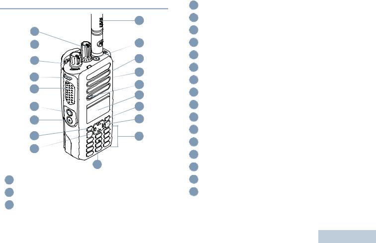
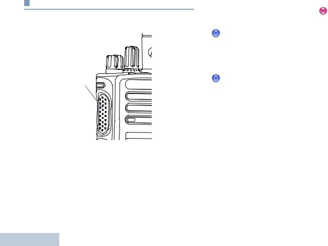
1Channel Selector Knob*
2On/Off/Volume Control Knob
3LED Indicator
4Side Button 1**
5Push-to-Talk (PTT) Button
6Side Button 2**
7Side Button 3**
8Front Button P1**
9Menu/OK Button
104-Way Navigation Button
11Keypad
12Back/Home Button
13Front Button P2**
14Display
15Microphone
16Speaker
17Universal Connector for Accessories
18Emergency Button**
19Antenna
*Display radios have a continuous-rotary Channel Selector Knob
**These buttons are programmable.
Controls Radio Identifying
7
English

Identifying Radio Controls
8
 Programmable Buttons
Your dealer can program the programmable buttons as shortcuts to radio functions or preset channels/groups depending on the duration of a button press:
•Short press – Pressing and releasing rapidly.
•Long press – Pressing and holding for the programmed duration.
•Hold down – Keeping the button pressed.
NOTE: The programmed duration of a button press is applicable for all assignable radio/utility functions or settings. See Emergency Operation on page 55 for more information on the programmed duration of the
Emergency button.
Assignable Radio Functions
Bluetooth® Audio Switch – Toggles audio routing between internal radio speaker and external Bluetooth-enabled accessory.
Contacts – Provides direct access to the contacts list.
Call Alert – Provides direct access to the contacts list for you to select a contact to whom a Call Alert can be sent.
Call Forwarding – Toggles Call Forwarding on or off.
Call Log – Selects the call log list.
Voice Announcement for Channel – Plays zone and channel announcement voice messages for the current channel. This function is unavailable when Voice Announcement is disabled.
Emergency – Depending on the programming, initiates or cancels an emergency alarm or call.
Intelligent Audio On/Off – Toggles Intelligent Audio on or off.
Manual Dial – Initiates a call by keying in any subscriber ID.
Manual Site Roam*‡  – Starts the manual site search.
Mic AGC On/Off – Toggles the internal microphone automatic gain control (AGC) on or off. Not applicable during a Bluetooth session.
Monitor – Monitors a selected channel for activity.
Nuisance Channel Delete*‡ – Temporarily removes an unwanted channel, except for the Selected Channel, from the scan list. The Selected Channel refers to the user’s selected zone/channel combination from which scan is initiated.
One Touch Access – Directly initiates a predefined Private or Group Call, a Call Alert or a Quick Text message.
Option Board Feature – Toggles option board feature(s) on or off for option board-enabled channels.
* Not applicable in Capacity Plus
‡ Not applicable in Linked Capacity Plus
English
Permanent Monitor*‡ – Monitors a selected channel for all radio traffic until function is disabled.
Privacy  – Toggles privacy on or off.
Radio Alias and ID – Provides radio alias and ID.
Radio Check  – Determines if a radio is active in a system.
Radio Enable  – Allows a target radio to be remotely enabled.
Radio Disable  – Allows a target radio to be remotely disabled.
Remote Monitor  – Turns on the microphone of a target radio without it giving any indicators.
Repeater/Talkaround*‡ – Toggles between using a repeater and communicating directly with another radio.
Scan*‡ – Toggles scan on or off.
Site Lock On/Off* – Toggles the automatic site roam on or off.
Status – Selects the status list menu.
Telemetry Control – Controls the Output Pin on a local or remote radio.
Text Message – Selects the text message menu.
Transmit Interrupt Remote Dekey |
– Stops the |
transmission of a remote monitored radio without giving any indicators, or an ongoing interruptible call to free the channel.
Voice Announcement On/Off – Toggles Voice Announcement on or off.
Voice Operating Transmission (VOX) – Toggles VOX on or off.
Zone – Allows selection from a list of zones.
* Not applicable in Capacity Plus
‡Not applicable in Linked Capacity Plus
Assignable Settings or Utility Functions
All Tones/Alerts – Toggles all tones and alerts on or off.
Backlight On/Off – Toggles display backlight on or off.
Backlight Brightness – Adjusts the brightness level.
Display Mode – Toggles the day/night display mode on or off.
Keypad Lock – Toggles keypad between locked and unlocked.
Power Level – Toggles transmit power level between high and low.
Squelch  – Toggles squelch level between tight and normal.
Controls Radio Identifying
9
English

Identifying Radio Controls
10
 Using the 4-Way Navigation Button
You can use the 4-way navigation button, e, to scroll through options, increase/decrease values, and navigate vertically.
Category |
^ or v |
< or > |
|
|
|
Menu |
Vertical Navigation |
– |
|
|
|
Lists |
Vertical Navigation |
– |
|
|
|
View Details |
Vertical Navigation |
Previous/Next Item |
|
|
|
You can use the 4-way navigation button, e, as a number, alias, or free form text editor.
Editor Category |
^ or v |
< or > |
|
|
|
|
|
Number |
– |
Left: Delete last digit |
|
Right: – |
|||
|
|
||
|
|
|
|
Alias |
– |
Move cursor one |
|
character left/right |
|||
|
|
||
|
|
|
|
Free Form Text |
Move cursor up/ |
Move cursor one |
|
down |
character left/right |
||
|
|||
|
|
|
|
Numeric Values |
Increase/Decrease |
– |
|
|
|
|
 Accessing the Programmed Functions
You can access various radio functions through one of the following ways:
• A short or long press of the |
ced |
|
relevant programmable buttons. |
||
|
||
OR |
|
• Use the 4-way navigation button as follows:
1To access the menu, press the cbutton. Press the appropriate direction of the eto access the menu functions.
2To select a function or enter a sub-menu, press the c button.
3To go back one menu level, or to return to the previous screen, press the dbutton. Long press the dbutton to return to the Home screen.
NOTE: Your radio automatically exits the menu after a period of inactivity and returns to your Home screen.
English


 Using the Keypad
You can use the 3 x 4 alphanumeric keypad to access your radio’s features. You can use the keypad to enter subscriber aliases or IDs, and text messages. Many characters require that you press a key multiple times. The table below shows the number of times a key needs to be pressed to generate the required character.
|
|
|
|
|
Number of Times Key is Pressed |
|
|
|
|
|
|||
|
|
|
|
|
|
|
|
|
|
|
|
|
|
Key |
1 |
2 |
3 |
4 |
5 |
6 |
7 |
8 |
9 |
10 |
11 |
12 |
13 |
|
|
|
|
|
|
|
|
|
|
|
|
|
|
1 |
1 |
. |
, |
? |
! |
@ |
& |
‘ |
% |
- |
: |
* |
# |
2 |
A |
B |
C |
2 |
|
|
|
|
|
|
|
|
|
3 |
D |
E |
F |
3 |
|
|
|
|
|
|
|
|
|
4 |
G |
H |
I |
4 |
|
|
|
|
|
|
|
|
|
5 |
J |
K |
L |
5 |
|
|
|
|
|
|
|
|
|
6 |
M |
N |
O |
6 |
|
|
|
|
|
|
|
|
|
7 |
P |
Q |
R |
S |
7 |
|
|
|
|
|
|
|
|
8 |
T |
U |
V |
8 |
|
|
|
|
|
|
|
|
|
9 |
W |
X |
Y |
Z |
9 |
|
|
|
|
|
|
|
|
0 |
0 |
NOTE: Press to enter “0” and long press to activate the CAPS lock. Another long press to turn off the CAPS lock. |
|
||||||||||
** or del NOTE: Press during text entry to delete the character. Press during numeric entry to enter a “*”.
# # or space NOTE: Press during text entry to insert a space. Press during numeric entry to enter a “#”.
Controls Radio Identifying
11
English
Identifying Radio Controls
12
Push-To-Talk (PTT) Button
The PTT button on the side of the radio serves two basic purposes:
PTT Button
•While a call is in progress, the PTT button allows the radio to transmit to other radios in the call.
Press and hold down PTT button to talk. Release the PTT button to listen.
The microphone is activated when the PTT button is pressed.
•While a call is not in progress, the PTT button is used to make a new call (see Making a Radio Call on page 27).
If the Talk Permit Tone (see Turning the Talk Permit Tone On
or Off on page 86) or the PTT Sidetone |
is enabled, wait |
until the short alert tone ends before talking.
During a call, if the Channel Free Indication feature is enabled on your radio (programmed by your dealer), you hear a short alert tone the moment the target radio (the radio that is receiving your call) releases the PTT button, indicating the channel is free for you to respond.
You will also hear a continuous talk prohibit tone, if your call is interrupted, indicating that you should release the PTT button, for example when the radio receives an Emergency Call.
English
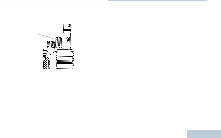
 Switching Between Conventional Analog
and Digital Mode
Each channel in your radio can be configured as a conventional analog or conventional digital channel. Use the Channel Selector Knob to switch between an analog or a digital channel.
Channel
Selector
Knob
When switching from digital to analog mode, certain features are unavailable. Icons for the digital features (such as Messages) reflect this change by appearing ‘grayed out’. Disabled features are hidden in the menu.
Your radio also has features available in both analog and digital mode. However, the minor differences in the way each feature works does NOT affect the performance of your radio.
NOTE: Your radio also switches between digital and analog modes during a dual mode scan (see Scan on page 41).
 IP Site Connect
This feature allows your radio to extend conventional communication beyond the reach of a single site, by connecting to different available sites which are connected via an Internet Protocol (IP) network.
When the radio moves out of range from one site and into the range of another, it connects to the new site's repeater to send or receive calls/data transmissions. Depending on your settings, this is done automatically or manually.
If the radio is set to do this automatically, it scans through all available sites when the signal from the current site is weak or when the radio is unable to detect any signal from the current site. It then locks on to the repeater with the strongest Received Signal Strength Indicator (RSSI) value.
In a manual site search, the radio searches for the next site in the roam list that is currently in range (but which may not have the strongest signal) and locks on to it.
NOTE: Each channel can only have either Scan or Roam enabled, not both at the same time.
Channels with this feature enabled can be added to a particular roam list. The radio searches the channel(s) in the roam list during the automatic roam operation to locate the best site.
A roam list supports a maximum of 16 channels (including the Selected Channel).
Controls Radio Identifying
13
English

Identifying Radio Controls
14
NOTE: You cannot manually add or delete an entry to the roam list. Check with your dealer or system administrator for more information.
 Capacity Plus
Capacity Plus is a single-site trunking configuration of the MOTOTRBO radio system, which uses a pool of channels to support hundreds of users and up to 254 Groups. This feature allows your radio to efficiently utilize the available number of programmed channels while in Repeater Mode.
Icons of features not applicable to Capacity Plus are not available in the menu. You hear a negative indicator tone if you try to access a feature not applicable to Capacity Plus via a programmable button press.
Your radio also has features that are available in conventional digital mode, IP Site Connect, Capacity Plus and Linked Capacity Plus. However, the minor differences in the way each feature works does NOT affect the performance of your radio.
Check with your dealer or system administrator for more information on this configuration.
 Linked Capacity Plus
Linked Capacity Plus is a multi-site multi-channel trunking configuration of the MOTOTRBO radio system, combining the best of both Capacity Plus and IP Site Connect configurations.
Linked Capacity Plus allows your radio to extend trunking communication beyond the reach of a single site, by connecting to different available sites which are connected via an Internet Protocol (IP) network. It also provides an increase in capacity by efficiently utilizing the combined available number of programmed channels supported by each of the available sites.
When the radio moves out of range from one site and into the range of another, it connects to the new site's repeater to send or receive calls/data transmissions. Depending on your settings, this is done automatically or manually.
If the radio is set to do this automatically, it scans through all available sites when the signal from the current site is weak or when the radio is unable to detect any signal from the current site. It then locks on to the repeater with the strongest Received Signal Strength Indicator (RSSI) value.
In a manual site search, the radio searches for the next site in the roam list that is currently in range (but which may not have the strongest signal) and locks on to it.
Any channel with Linked Capacity Plus enabled can be added to a particular roam list. The radio searches these channels during the automatic roam operation to locate the best site.
English

NOTE: You cannot manually add or delete an entry to the roam list. Check with your dealer or system administrator for more information.
Similar to Capacity Plus, icons of features not applicable to Linked Capacity Plus are not available in the menu. You hear a negative indicator tone if you try to access a feature not applicable to Linked Capacity Plus via a programmable button press.
Check with your dealer or system administrator for more information on this configuration.
Identifying Status Indicators
Your radio indicates its operational status through the following: Display Icons . . . . . . . . . . . . . . . . . . . . . . . . . . . . . . . . page 16 Call Icons . . . . . . . . . . . . . . . . . . . . . . . . . . . . . . . . . . . page 17 Advanced Menu Icons . . . . . . . . . . . . . . . . . . . . . . . . . page 18 Mini Notice Icons . . . . . . . . . . . . . . . . . . . . . . . . . . . . . page 18 Sent Item Icons . . . . . . . . . . . . . . . . . . . . . . . . . . . . . .page 19 Bluetooth Device Icons . . . . . . . . . . . . . . . . . . . . . . . . page 19 LED Indicator . . . . . . . . . . . . . . . . . . . . . . . . . . . . . . . . page 20 Audio Tones . . . . . . . . . . . . . . . . . . . . . . . . . . . . . . . . . page 21 Indicator Tones. . . . . . . . . . . . . . . . . . . . . . . . . . . . . . . page 21
Indicators Status Identifying
15
English
Identifying Status Indicators
16
 Display Icons
The 132 x 90 pixels, 256 colors, liquid crystal display (LCD) of your radio shows radio status, text entries, and menu entries.
The following are icons that appear on the status bar at the top of the radio’s display. Icons are displayed on the status bar, arranged left-to-right, in order of appearance/usage and are channel specific.
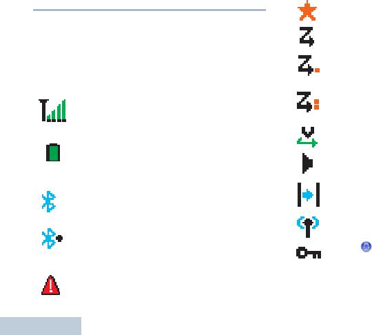
Received Signal Strength Indicator (RSSI)
The number of bars displayed represents the radio signal strength. Four bars indicate the strongest signal. This icon is only displayed while receiving.
Battery
The number of bars (0 – 4) shown indicates the charge remaining in the battery.
Blinks when the battery is low.
Bluetooth
The Bluetooth feature is enabled but there is no remote Bluetooth device connected.
Bluetooth Connected
The Bluetooth feature is enabled. The icon stays lit when one or more remote Bluetooth devices are connected.
Emergency
Radio is in Emergency mode.
Notification
Notification List has one or more missed events.
Scan*‡
Scan feature is enabled.
Scan – Priority 1*‡
Radio detects activity on channel/group designated as Priority 1).
Scan – Priority 2*‡
Radio detects activity on channel/group designated as Priority 2.
Vote Scan
Vote scan feature is enabled.
Monitor
Selected channel is being monitored.
Talkaround*‡
In the absence of a repeater, radio is currently configured for direct radio to radio communication.
Site Roaming* 
The site roaming feature is enabled.
Secure
The Privacy feature is enabled.
*Not applicable in Capacity Plus
‡Not applicable in Linked Capacity Plus
English
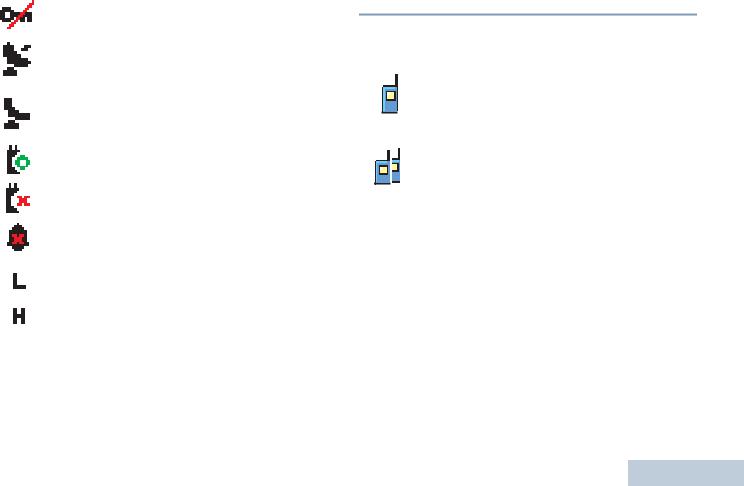
Unsecure 
The Privacy feature is disabled.
GPS Available 
The GPS feature is enabled. The icon stays lit when a position fix is available.
GPS Not Available/Out of Range 
The GPS feature is enabled but is not receiving data from the satellite.
Option Board
The Option Board is enabled.
Option Board Non-Function
The Option Board is disabled.
Tones Disable
Tones are turned off.
Power Level
Radio is set at Low power.
OR
Radio is set at High power.
* Not applicable in Capacity Plus
‡ Not applicable in Linked Capacity Plus
 Call Icons
The following icons appear on the radio’s display during a call. These icons also appear in the Contacts list to indicate ID type.
Private Call
Indicates a Private Call in progress.
In the Contacts list, it indicates a subscriber alias (name) or ID (number).
Group Call/All Call
Indicates a Group Call or All Call in progress.
In the Contacts list, it indicates a group alias (name) or ID (number).
Indicators Status Identifying
17
English
Identifying Status Indicators
18
 Advanced Menu Icons
The following icons appear beside menu items that offer a choice between two options or as an indication that there is a sub-menu offering two options.
Checkbox (Empty)
Indicates the option is not selected.
Checkbox (Checked)
Indicates the option is selected.
Solid Black Box
Indicates the option selected for the menu item with a sub-menu.
 Mini Notice Icons
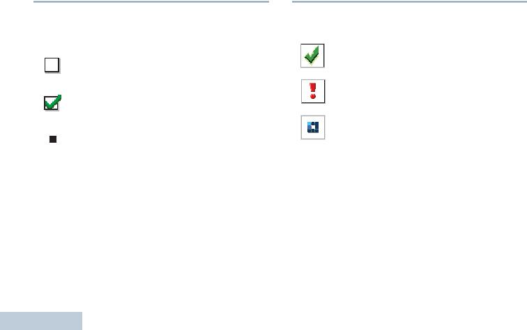
The following icons appear momentarily on the radio’s display after an action to perform task is taken.
Successful Transmission (Positive)
Successful action taken.
Failed Transmission (Negative)
Failed action taken.
Transmission in Progress (Transitional)
Transmitting. This dynamic icon is seen before indication for Successful Transmission or Failed Transmission.
English
Loading...