


 Loading...
S T A R L I N E ®
S G 2 0 0 0
T e l e c o m m u n i c a t i o n s O p t i c a l N o d e I n s t a l l a t i o n a n d O p e r a t i o n M a n u a l
4
2
6
IN
7

Caution
These servicing instructions are for use by qualified personnel only. To reduce the risk of electrical shock, do not perform any servicing other than that contained in the Installation and Troubleshooting Instructions unless you are qualified to do so. Refer all servicing to qualified service personnel.
Special Symbols that Might Appear on the Equipment
This is a class 1 product that contains a class IIIb laser and is intended for operation in a closed environment with fiber attached. Do not look into the optical connector of the transmitter with power applied. Laser output is invisible, and eye damage result. Do not defeat safety features that prevent looking into optical connector.
This product contains a class IIIb laser and is intended for operation in a closed environment with fiber attached. Do not look into the optical connector of the transmitter with power applied. Laser output is invisible, and eye damage can result. Do not defeat safety features that prevent looking into optical connector.
This symbol indicates that dangerous voltage levels are present within the equipment. These voltages are not insulated and may be of sufficient strength to cause serious bodily injury when touched. The symbol may also appear on schematics.
The exclamation point, within an equilateral triangle, is intended to alert the user to the presence of important installation, servicing, and operating instructions in the documents accompanying the equipment.
For continued protection against fire, replace all fuses only with fuses having the same electrical ratings marked at the location of the fuse.
Copyright © 2001 by Motorola Inc.
All rights reserved. No part of this publication may be reproduced in any form or by any means or used to make any derivative work (such as translation, transformation or adaptation) without written permission from Motorola, Inc.
Motorola, Inc. reserves the right to revise this publication and to make changes in content from time to time without obligation on the part Motorola, Inc. to provide notification of such revision or change. Motorola Inc. provides this guide without warranty of any kind, either implied or expressed, including, but not limited, to the implied warranties of merchantability and fitness for a particular purpose. Motorola, Inc. may make improvements or changes in the product(s) described in this manual at any time.
________________________________________________________________________________________________________________________________
MOTOROLA, the stylized M logo, and STARLINE are registered trademarks, and LIFELINE is a trademark of Motorola, Inc. All other product or service names are the property of their respective owners.

Contents
Section 1
I n t r o d u c t io n
Using this Manual .......................................................................................................................................... |
1-3 |
Related Documentation .................................................................................................................................. |
1-3 |
Document Conventions .................................................................................................................................. |
1-4 |
If You Need Help ........................................................................................................................................... |
1-4 |
Calling for Repairs......................................................................................................................................... |
1-5 |
Section 2 |
|
O v e r v ie w |
|
Housing ........................................................................................................................................................ |
2-1 |
Mounting Holes ...................................................................................................................................... |
2-1 |
Port Locations ........................................................................................................................................ |
2-2 |
Gaskets ................................................................................................................................................. |
2-3 |
Power Supply ................................................................................................................................................ |
2-4 |
Network Monitoring ........................................................................................................................................ |
2-5 |
Configuration ................................................................................................................................................ |
2-5 |
Forward Path................................................................................................................................................. |
2-7 |
SG2-LR Receiver ................................................................................................................................... |
2-9 |
Analog Return Path ..................................................................................................................................... |
2-10 |
Analog Return Transmitters .................................................................................................................. |
2-10 |
Digital Return Path ...................................................................................................................................... |
2-12 |
DS-SG2-DRT/A .................................................................................................................................... |
2-12 |
DS-SG2-DRT-2X/A ............................................................................................................................... |
2-13 |
Level Control............................................................................................................................................... |
2-14 |
Options and Accessories.............................................................................................................................. |
2-14 |
Gain Selection...................................................................................................................................... |
2-16 |
Tilt Selection ........................................................................................................................................ |
2-18 |
Section 3 |
|
Bench Setup |
|
Powering the Node ........................................................................................................................................ |
3-3 |
Power Supply Settings ................................................................................................................................... |
3-5 |
Single Power Supply or Commonly Powered Redundant Supplies ............................................................. |
3-7 |
Individually Powered Supplies ................................................................................................................. |
3-7 |
SG 2000 Installation and O peration Manual
i i |
C o n t e n t s |
Quick Checks - Functional Testing ................................................................................................................. |
3-8 |
Forward Path ......................................................................................................................................... |
3-8 |
Manual Gain Control ....................................................................................................................... |
3-9 |
Thermal Control, Model TCU ........................................................................................................... |
3-9 |
Automatic Level Control, Model ADU................................................................................................ |
3-9 |
Analog Return Path .............................................................................................................................. |
3-10 |
Digital Return Path ............................................................................................................................... |
3-10 |
Forward Path Padding ................................................................................................................................. |
3-11 |
Launch Amplifier Output Stage Padding........................................................................................................ |
3-14 |
Link Performance ........................................................................................................................................ |
3-15 |
Installing the DS-SG2-DRRB Board Option ................................................................................................... |
3-18 |
Installing the Status Monitor Option.............................................................................................................. |
3-22 |
SG 2000 Activation Worksheet ..................................................................................................................... |
3-23 |
Section 4 |
|
I n s ta l l a ti o n |
|
Splicing Fiber ................................................................................................................................................ |
4-1 |
Strand Wire Mounting .................................................................................................................................... |
4-3 |
Coaxial Cables .............................................................................................................................................. |
4-5 |
Fiber Cables ................................................................................................................................................. |
4-5 |
Section 5 |
|
O p e r a t io n |
|
Forward Path RF Configuration ...................................................................................................................... |
5-1 |
Single Receiver Mode............................................................................................................................. |
5-1 |
Redundant Receiver Mode ...................................................................................................................... |
5-2 |
Broadband/Narrowcast Mode .................................................................................................................. |
5-2 |
AB Override Functionality ....................................................................................................................... |
5-3 |
B Override ...................................................................................................................................... |
5-3 |
A Override ...................................................................................................................................... |
5-4 |
Status Monitor/Manual Control Operation ......................................................................................... |
5-4 |
Analog Return Path RF Configuration ............................................................................................................. |
5-5 |
Digital Return Path RF Configuration .............................................................................................................. |
5-7 |
SG 2000 Optical Modules .............................................................................................................................. |
5-9 |
Installing SG 2000 Optical Modules ......................................................................................................... |
5-9 |
Removing SG 2000 Optical Modules ....................................................................................................... |
5-9 |
Cleaning the Optical Connector............................................................................................................. |
5-10 |
SG2-LR Optical Receiver ............................................................................................................................. |
5-10 |
Wavelength Selection Jumper ...................................................................................................................... |
5-13 |
SG2-IFPT Optical Transmitter ...................................................................................................................... |
5-14 |
SG2-FPT Optical Transmitter ....................................................................................................................... |
5-15 |
SG2-DFBT Optical Transmitter ..................................................................................................................... |
5-16 |
SG 2000 Installation and O peration Manual
C o n t e n t s |
i i i |
SG2-DFBT/3 Optical Transmitter .................................................................................................................. |
5-18 |
SG2-EIFPT Optical Transmitter .................................................................................................................... |
5-19 |
DS-SG2-DRT/A Digital Return Transmitter .................................................................................................... |
5-20 |
DS-SG2-DRT-2X/A Digital Return Transmitter ............................................................................................... |
5-22 |
SG2-PS Power Supply .......................................................................................................................... |
5-25 |
Status Monitoring ........................................................................................................................................ |
5-26 |
Manual Control Board .................................................................................................................................. |
5-27 |
Ingress Control............................................................................................................................................ |
5-29 |
Appendix A
S p e c i f ic a t i o n s
Appendix B
Torque Specifications
Abbreviations and Acronyms
Figures
Figure 1-1 |
SG 2000 — closed ............................................................................................ |
1-1 |
Figure 1-2 |
SG 2000 — open .............................................................................................. |
1-2 |
Figure 2-1 |
SG 2000 housing dimensions - front and side view ............................................. |
2-1 |
Figure 2-2 |
Port locations ................................................................................................... |
2-2 |
Figure 2-3 |
Housing gaskets ............................................................................................... |
2-3 |
Figure 2-4 |
SG2-PS2 power supply ..................................................................................... |
2-4 |
Figure 2-5 |
Configuration notation....................................................................................... |
2-6 |
Figure 2-6 |
Signal flow diagram .......................................................................................... |
2-7 |
Figure 2-7 |
SG2-LR receiver functional diagram .................................................................. |
2-9 |
Figure 2-8 |
SG2 transmitter block diagram ........................................................................ |
2-11 |
Figure 2-9 |
Optical input versus 750 MHz gain................................................................... |
2-16 |
Figure 2-10 |
Optical input versus 870 MHz gain................................................................. |
2-17 |
Figure 2-11 |
Relative level dB versus 750 MHz slope 77 channels...................................... |
2-18 |
Figure 2-12 |
Relative level dB versus 870 MHz slope 94 channels...................................... |
2-19 |
Figure 2-13 |
Relative level dB versus 870 MHz slope 110 channels .................................... |
2-20 |
Figure 3-1 |
SG 2000 lid showing major components............................................................. |
3-1 |
Figure 3-2 |
SG 2000 RF chassis ......................................................................................... |
3-2 |
Figure 3-3 |
Fuse configuration ............................................................................................ |
3-3 |
Figure 3-4 |
Fuse locations .................................................................................................. |
3-5 |
Figure 3-5 |
SG2-PS2 power supply ..................................................................................... |
3-6 |
SG 2000 Installation and O peration Manual
i v |
C o n t e n t s |
Figure 3-6 |
JP1 common-powered single or redundant power configuration .......................... |
3-7 |
Figure 3-7 |
JP1 split-powered redundant power supply configuration ................................... |
3-7 |
Figure 3-8 |
SG2-75 low-gain output-stage pad-effects chart .............................................. |
3-14 |
Figure 3-9 |
SG2-87 low-gain output-stage pad-effects chart .............................................. |
3-15 |
Figure 3-10 |
SG2-* link c/n performance, 77 channels ....................................................... |
3-16 |
Figure 3-11 |
SG2-* link c/n performance, 110 channels ..................................................... |
3-17 |
Figure 3-12 |
DS-SG2-DRRB board ................................................................................... |
3-18 |
Figure 3-13 |
DS-SG2-DRRB board installed...................................................................... |
3-19 |
Figure 3-14 |
Location of JXPs on E-pack .......................................................................... |
3-20 |
Figure 3-15 |
SG2 lid configured with the DS-SG2-DRRB board .......................................... |
3-21 |
Figure 4-1 |
Service cable connection and compression fitting .............................................. |
4-1 |
Figure 4-2 |
Mounting bracket-front view.............................................................................. |
4-3 |
Figure 4-3 |
Mounting bracket-rear and side views ............................................................... |
4-4 |
Figure 4-4 |
Center conductor length ................................................................................... |
4-5 |
Figure 4-5 |
Housing lid and fiber spool tray......................................................................... |
4-6 |
Figure 4-6 |
Fiber spool tray ................................................................................................ |
4-6 |
Figure 5-1 |
Single receiver ................................................................................................. |
5-1 |
Figure 5-2 |
Redundant receiver .......................................................................................... |
5-2 |
Figure 5-3 |
Broadband/narrowcast...................................................................................... |
5-2 |
Figure 5-4 |
B override ........................................................................................................ |
5-3 |
Figure 5-5 |
A override ........................................................................................................ |
5-4 |
Figure 5-6 |
Status monitor/MCB operation .......................................................................... |
5-4 |
Figure 5-7 |
Redundant return ............................................................................................. |
5-5 |
Figure 5-8 |
Split return....................................................................................................... |
5-5 |
Figure 5-9 |
RF chassis and location of the SG2-RPM/C or SG2-RPM/S board ...................... |
5-6 |
Figure 5-10 |
DS-SG2-DRT/A redundant return .................................................................... |
5-7 |
Figure 5-11 |
DS-SG2-DRT-2X/A split return ........................................................................ |
5-8 |
Figure 5-12 |
DS-SG2-DRT-2X/A redundant return ............................................................... |
5-8 |
Figure 5-13 |
SG2-LR ....................................................................................................... |
5-10 |
Figure 5-14 |
Test-point voltage versus optical power ......................................................... |
5-12 |
Figure 5-15 |
Wavelength selection jumper ........................................................................ |
5-13 |
Figure 5-16 |
SG2-IFPT .................................................................................................... |
5-14 |
Figure 5-17 |
SG2-FPT ..................................................................................................... |
5-15 |
Figure 5-18 |
SG2-DFBT ................................................................................................... |
5-16 |
Figure 5-19 |
SG2-DFBT/3 ................................................................................................ |
5-18 |
Figure 5-20 |
SG2-EIFPT .................................................................................................. |
5-19 |
Figure 5-21 |
DS-SG2-DRT/A ............................................................................................ |
5-20 |
Figure 5-22 |
DS-SG2-DRT/A ............................................................................................ |
5-20 |
SG 2000 Installation and O peration Manual
C o n t e n t s |
v |
Figure 5-23 |
DS-SG2-DRT-2X/A........................................................................................ |
5-22 |
Figure 5-24 |
DS-SG2-DRT-2X/A........................................................................................ |
5-22 |
Figure 5-25 |
DS-SG2-DRT-2X/A cable connector ............................................................... |
5-24 |
Figure 5-26 |
DS-SG2-DRT-2X/A installed in SG 2000 ........................................................ |
5-24 |
Figure 5-27 |
DS-SG2-DRT-2X/A second RF input cable connection .................................... |
5-25 |
Figure 5-28 |
SG2-PS power supply ................................................................................... |
5-25 |
Figure 5-29 |
MCB board ................................................................................................... |
5-28 |
Tables
Table 2-1 |
Analog return transmitters ................................................................................ |
2-10 |
Table 2-2 |
Digital return transmitters ................................................................................. |
2-12 |
Table 2-3 |
Options and accessories .................................................................................. |
2-14 |
Table 3-1 |
AC fuses ........................................................................................................... |
3-4 |
Table 3-2 |
SG 2000 pad chart-standard gain ..................................................................... |
3-12 |
Table 3-3 |
SG 2000 pad chart-high gain ............................................................................ |
3-13 |
Table 3-4 |
Common problems ........................................................................................... |
3-22 |
Table 5-1 |
SG2-LR features .............................................................................................. |
5-11 |
Table 5-2 |
SG2-LR minimum output levels......................................................................... |
5-11 |
Table 5-3 |
SG2-IFPT features ........................................................................................... |
5-14 |
Table 5-4 |
SG2-FPT features ............................................................................................ |
5-15 |
Table 5-5 |
SG2-DFBT features.......................................................................................... |
5-16 |
Table 5-6 |
SG2-DFBT/3 features....................................................................................... |
5-18 |
Table 5-7 |
SG2-EIFPT features......................................................................................... |
5-19 |
Table 5-8 |
DS-SG2-DRT/A features................................................................................... |
5-21 |
Table 5-9 |
DS-SG2-DRT-2X/A features ............................................................................. |
5-23 |
Table 5-10 |
Reporting and control provisions..................................................................... |
5-26 |
Table 5-11 |
MCB user-interface settings............................................................................ |
5-27 |
Table A-1 |
SG 2000 optical characteristics ......................................................................... |
A-1 |
Table A-2 |
Station RF characteristics ................................................................................. |
A-1 |
Table A-3 |
SG 2000 General characteristics ....................................................................... |
A-2 |
Table A-4 |
SG2-LR specifications ...................................................................................... |
A-2 |
Table A-5 |
SG2-IFPT RF specifications .............................................................................. |
A-3 |
Table A-6 |
SG2-FPT RF specifications ............................................................................... |
A-3 |
Table A-7 |
SG2-DFBT RF specifications............................................................................. |
A-4 |
Table A-8 |
SG2-DFBT/3 RF specifications .......................................................................... |
A-4 |
Table A-9 |
SG2-EIFPT RF specifications ............................................................................ |
A-5 |
Table A-10 |
SG2-DRT/A RF specifications ......................................................................... |
A-5 |
Table A-11 |
SG2-DRT-2X/A RF specifications .................................................................... |
A-6 |
Table A-12 |
Optical output power vs. wavelength for DS-SG2-DRT*/A transmitters .............. |
A-6 |
SG 2000 Installation and O peration Manual
v i |
C o n t e n t s |
Table A-13 |
Current requirements ...................................................................................... |
A-7 |
Table A-14 |
SG2-75 performance, with 77 channels ............................................................ |
A-8 |
Table A-15 |
SG2-87 performance, with 94 channels ............................................................ |
A-8 |
Table A-16 |
SG2-87 performance, with 110 channels .......................................................... |
A-8 |
SG 2000 Installation and O peration Manual
Section 1
Introduction
Motorola’s SG 2000 telecommunications optical node performs light wave-to-RF and RF-to-light wave signal conversions in an optical transmission link. This product is designed to support a wide variety of advanced hybrid-fiber/coaxial network topologies.
As broadband communication systems continue to evolve, the demand increases for optical links that carry the signal further into the transport system. These systems require additional features and functionality such as digital compression and alternate access at significantly lower costs. Fully configured, the SG 2000 supports these next-generation telecommunication networks. It also supports a variety of single and two-way broadband network applications such as broadcast video, interactive video, telephony, and data.
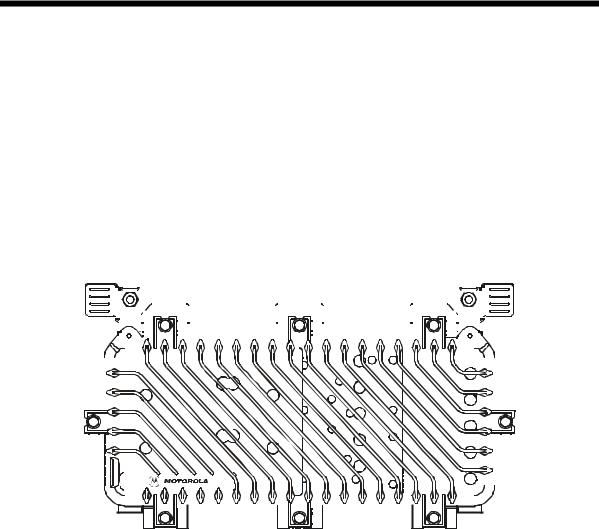
Figure 1-1 illustrates a closed SG 2000 telecommunications optical node:
Figure 1-1
SG 2000 — closed
|
|
|
|
|
|
|
|
|
|
|
|
|
|
|
|
|
|
|
|
|
|
|
|
|
|
|
|
|
|
|
|
|
|
|
|
|
|
|
|
|
|
|
|
|
|
|
|
|
|
|
|
|
|
|
|
|
|
6 |
|
|
|
|
|
2 |
|
|
|
|
|
4 |
|
|
|
|
|
|
|
|
|
|
|
|
|
|
|
|
|
|
|
|
|
|
|
|
|
|
|
|
|
|
|||
|
|
|
|
|
|
|
|
|
|
|
|
|
|
|
|
|
|
|
|
|
|||||
|
|
|
|
|
|
|
|
|
|
|
|
|
|
|
|
|
|
|
|
|
|
|
|
|
|
|
|
|
|
|
|
|
|
|
|
|
|
|
|
|
|
|
|
|
|
|
|
|
|
7 |
|
|
|
|
|
|
|
8 |
|
||
|
|
|
|
|
|
|
|
|
|
|
|
|
|
|
|
|
|
|
|
|
|
|
|
|
|
|
|
|
|
|
|
|
|
|
|
|
|
|
|
|
|
|
|
|
|
|
|
|
|
|
|
|
|
|
|
|
|
|
|
|
|
|
|
|
|
|
|
|
|
|
|
|
|
|
|
|
|
|
|
|
|
|
|
|
|
|
|
|
|
|
|
|
|
|
|
|
|
|
|
|
|
|
|
|
|
|
|
3 
 1
1 
 5
5
SG 2000 Installation and O peration Manual

1 - 2 |
I n t r o d u c t i o n |
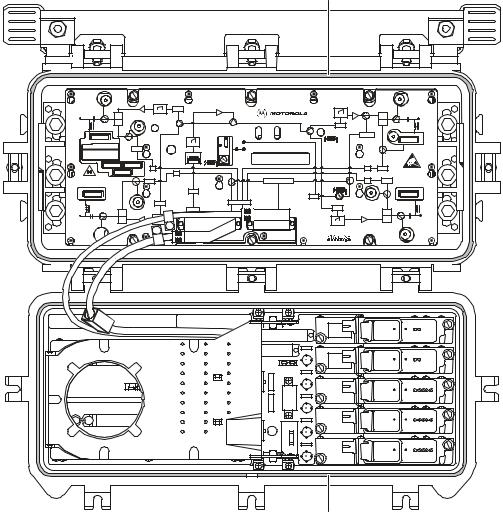
Figure 1-2 illustrates an open SG 2000 telecommunications optical node:
Figure 1-2
SG 2000 — open
|
|
|
|
|
|
|
|
-20dB |
-20dB |
|
|
|
|
|
|
|
|
|
JXP 1 |
|
|
|
|
|
|
|
|
FWD EQ |
|
|
|
|
|
|
|
H |
|
|
|
|
FWD EQ |
|
H |
|
PORT 1 |
|
|
|
|
|
|
|
PORT 2 |
L |
ON |
|
|
|
JXP 2 |
|
L |
|
|
|
|
|
|
|
|
|
|
|
-20dB |
|
|
ADU |
TCU |
JXP ADU |
|
|
|
|
|
|
|
|
|||
|
+24 V DC |
MDR |
|
|
ON |
|
|
|
FTEC |
JXP 1 |
|
|
|
|
-20dB |
||
|
|
|
|
|
|
|||
|
|
VARILOSSER |
MAN |
|
OFF |
|
|
|
|
|
|
|
SG2- |
|
|
|
|
|
|
|
|
|
|
|
|
|
|
IS |
|
|
|
|
IS |
JXP 2 |
CAUTION: |
|
IS |
|
|
|
|
|
|
CONTAINS PARTS |
|
|
|
|
|
|
|
ANDASSEMBLIES |
|
|
|
|
|
|
|
|
|
SUSCEPTIBLETO |
REFER TO |
JXP 3 |
STATUS MONITOR |
IS |
JXP 4 |
DAMAGE BY |
MANUAL FOR |
ELECTROSTATIC |
||||
FUSE VALUES |
|
|
ADU |
|
DISCHARGE(ESD) |
|
|
FRB |
|
|
|
|
|
ADU |
|
|
JXP 3 |
RPM/* |
SG 2000 |
-20dB |
|
-20dB |
RCVR |
JXP 4 |
|
L |
|
Optical Node |
L |
|
|
INPUT |
|||
PORT 3 |
|
|
|
PORT 4 |
H |
FWD EQ |
|
|
H |
|
|
|
FWD EQ |
-20dB
-20dB

ASSEMBLED IN MEXICO
Base
Lid
Features include:
!52 through 870 MHz forward passband, 5 through 40 MHz return standard (other splits are available, see Appendix A, “Specifications”)
!Optical receivers - up to three
!Optical transmitters - up to two
!Four independent RF outputs
!Ingress switching capability through manual or headend control
!Redundant powering capability
!15 A power passing
SG 2000 Installation and O peration Manual
I n t r o d u c t i o n |
1 - 3 |
!Optional LIFELINE™ status monitoring
!User-friendly fiber management
!60/90 volt powering
!Digital return redundancy capability
!Modular plug-in diplex filters and equalizers
!Custom configuration for unique system requirements
Using this Manual
The following sections provide information and instructions to install, configure, and operate the SG 2000:
Section 1 Introduction provides a brief description of the product, identifies the information contained in this manual, and gives the help line telephone number and repair return information.
Section 2 Overview describes the SG 2000 node and includes details regarding your options and their functions.
Section 3 Bench Setup provides full configuration, set-up of options, and bench testing procedures that are recommended before installation.
Section 4 Installation provides instructions for installing the SG 2000 in a distribution system.
Section 5 Operation provides information governing the use of various options and applications required by your system.
Appendix A Specifications provides technical specifications for the SG 2000 node and major options.
Appendix B Torque Specifications provides the appropriate torque specifications for the screws, clamps, connectors, and bolts used in the SG 2000.
Abbreviations The Abbreviations and Acronyms list contains the full spelling of the short forms and Acronyms used in this manual.
Related Documentation
Although these documents provide information that may be of interest to you, they are not required to install or operate the SG 2000.
#LL-CU LIFELINE Control Unit Installation and Operation Manual
#LIFELINE for Windows Site Preparation Guide
#LIFELINE for Windows Software Operations Manual
#Return Path Level Selection, Setup, and Alignment Procedure Reference Guide
SG 2000 Installation and O peration Manual
1 - 4 |
I n t r o d u c t i o n |
Document Conventions
Before you begin to use the SG 2000, familiarize yourself with the stylistic conventions used in this manual:
Bold type
SMALL CAPS
*
(Asterisk)
Italic type
Indicates text that you must type exactly as it appears or indicates a default value
Denotes silk screening on the equipment, typically representing front and rearpanel controls, I/O connections and indicators (LEDs).
Indicates that there are several versions of the same model number and the information applies to all models. When the information applies to a specific model, the complete model number is given.
Denotes a displayed variable, a variable that you must type, or is used for emphasis
If You Need Help
If you need assistance while working with the SG 2000, contact the Motorola Technical Response Center (TRC):
#Inside the U.S.: 1-888-944-HELP (1-888-944-4357)
#Outside the U.S.: 215-323-0044
#Online: http://www.motorola.com/broadband, click HTML/Modem Version, click Customer Support, then click Web Support.
The TRC is open from 8:00 a.m. to 7:00 p.m. Eastern Time, Monday through Friday and 10 AM to 6 PM Eastern Time, Saturday. When the TRC is closed, emergency service only is available on a call-back basis. Web Support offers a searchable solutions database, technical documentation, and low priority issue creation/tracking 24 hours per day, 7 days per week.
SG 2000 Installation and O peration Manual
I n t r o d u c t i o n |
1 - 5 |
Calling for Repairs
If repair is necessary, call the Motorola Repair Facility at 1-800-642-0442 for a Return for Service Authorization (RSA) number before sending the unit. The RSA number must be prominently displayed on all equipment cartons. The Repair Facility is open from 7 AM to 4 PM Pacific Time, Monday through Friday.
When calling from outside the United States, use the appropriate international access code and then call 526-314-1000, extension 3194, to contact the Repair Facility.
When shipping equipment for repair, follow these steps:
1Pack the unit securely.
2Enclose a note describing the exact problem.
3Enclose a copy of the invoice that verifies the warranty status.
4Ship the unit PREPAID to the following address: Motorola BCS
c/o Exel
Attn: RSA #___________
6908 East Century Park Dr. Tucson, AZ 85706
SG 2000 Installation and O peration Manual
Section 2
Overview
Designed to be flexible, you can configure the SG 2000 with up to three optical receivers, four independent high-level RF outputs, and two return-path optical transmitters. Multiple receiver and transmitter combinations are available to satisfy split-band or redundancy requirements. The forward passband is extended to 870 MHz to increase channel capacity and support advanced interactive services and global applications.
Housing
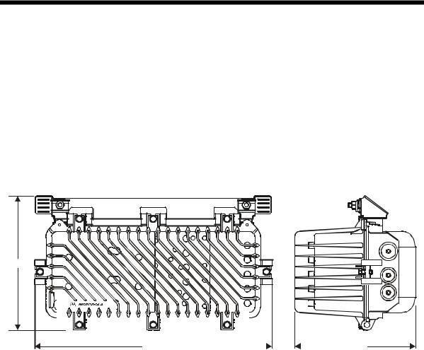
The aluminum housing protects the electronics from weather damage and dissipates internally generated heat. Figure 2-1 illustrates the housing dimensions of the SG 2000 optical node:
Figure 2-1
SG 2000 housing dimensions - front and side view
6 |
2 |
4 |
|
OUT |
12.25 |
|
7 |
8 |
|
4 |
|
3 |
|
|
|
|
|
|
|
|
|
|
|
|
|
|
|
|
|
|
|
|
|
|
|
|
|
|
|
|
|
|
|
|
|
|
|
|
|
|
|
|
|
|
|
|
|
|
|
|
|
|
|
|
|
|
|
|
|
|
|
|
|
|
|
|
|
|
|
|
|
|
|
|
|
|
|
|
|
|
|
|
|
|
|
|
|
|
|
|
|
|
|
|
|
|
|
|
|
|
|
|
|
|
|
|
|
|
|
|
|
|
|
|
|
|
|
|
3 |
|
|
|
|
1 |
|
|
|
5 |
|
|
|
|
|
|
|
|
|
|
|
|
|
|
|
|
|
|
|
|
|
|
|
|
|
|
|
|
21.60 |
|
|
|
10.99 |
|
|
For strand mounting, the optional bracket must be used. If the node is configured for strand mounting, the bracket is installed on the node at the factory. The bracket provides two clamps, located 16-7/8 inches apart, that secure the strand with 5/16 × 20 stainless steel bolts.
Coaxial cable connections to the housing are made using conventional 5/8 inch × 24 threads per inch, stinger-type connectors.
Mounting Holes
Two threaded holes are located on the horizontal centerline on the back of the housing. These 5/16 × 18 × ¾ holes are separated by 11 inches center-to-center and can be used for pedestal or surface mounting.
SG 2000 Installation and O peration Manual

2 - 2 |
O v e r v i e w |
Port Locations
The five housing ports, shown in Figure 2-2, provide connection for coaxial cables. Note that the housing ports are not labeled the same as the ports on the RF chassis. Side-by-side connector fittings are limited to .750 inches at ports 1 and 2 and/or ports 3 and 4. These ports are protected by factory inserted threaded plugs or plastic cap plugs which are discarded when the cable connectors are installed. Port 2 is used only for connection to an external 60 Vac or 90 Vac power supply. Port 4 is unused.
Figure 2-2 illustrates a front and end view of the housing and port locations:
Figure 2-2
Port locations
6 |
2 |
4 |
|
|
|
|
|
|
|
|
|
|
|
|
|
|
|
|
|
|
|
|
|
|
7 |
|
|
|
|
|
|
|
8 |
|
|
|
|
|
|
|
|
|
|
|
|
|
|
|
|
|
|
|
|
|
|
|
|
|
|
|
|
|
|
|
|
|
|
|
|
|
|
|
|
|
|
|
|
|
|
|
|
|
|
|
|
|
|
|
|
|
|
|
|
|
|
|
|
|
|
|
|
|
|
|
|
|
|
|
|
|
|
|
|
|
|
|
|
|
|
|
|
|
|
|
|
|
|
|
|
3 |
|
|
|
1 |
|
|
|
5 |
|
|
|
|
|
|
|
|
|
|
|
|
|
|
|
|
|
|
|
|
|
|
|
|
|
|
|
|
|
|
|
|
|
|
|
|
|
|
|
|
|
|
|
|
|
|
|
|
|
|
|
|
|
|
|
|
|
|
|
|
|
|
|
|
|
|
|
|
|
|
|
|
|
|
|
|
|
|
|
|
|
|
|
|
|
|
|
|
|
|
|
|
|
|
|
|
|
|
|
|
|
|
|
|
|
Port 1
AC port Port 3
IN |
|
|
|
OUT |
|
|
|
|
|
|
|
|
|
|
|
|
|
2 |
Lid |
4 |
|
1 |
|
|
|
|
|
|
|
|
3 |
|
|
||
|
|
|
|
|
|
|
|
|
|
|
|
|
|
|
|
|
|
|
|
|
|
|
|
|
|
|
|
|
|
|
|
|
|
|
|
|
|
|
|
|
|
|
|
|
|
|
|
|
|
|
|
|
|
|
|
|
|
|
|
|
|
|
|
|
|
|
|
|
|
|
|
|
|
|
|
|
|
|
|
|
|
|
|
|
|
|
|
|
|
Port 2
Unused
Port 4
SG 2000 Installation and O peration Manual
O v e r v i e w |
2 - 3 |
Gaskets
Each housing is equipped with a woven-wire gasket and a silicone-rubber weather gasket between the housing base and lid as shown in Figure 2-3:
Figure 2-3
Housing gaskets
Weather gasket (silicone rubber)
|
|
|
|
|
|
|
-20dB |
-20dB |
|
|
|
|
|
|
|
|
JXP 1 |
|
|
|
|
|
|
|
FWD EQ |
|
|
|
|
|
|
H |
|
|
|
FWD EQ |
|
H |
|
PORT 1 |
|
|
|
|
|
|
PORT 2 |
L |
ON |
|
|
JXP 2 |
|
L |
|
|
|
|
|
|
|
|
|
|
-20dB |
ADU |
|
TCU |
JXP ADU |
|
|
|
+24 V DC |
MDR |
ON |
|
|
|
|
FTEC |
JXP 1 |
|
|
-20dB |
|
||
|
OFF |
|
|
|
|||
|
|
VARILOSSER |
|
|
|
|
|
|
|
MAN |
SG2- |
|
|
|
|
|
|
|
|
|
|
|
|
|
IS |
|
|
|
IS |
JXP 2 |
CAUTION: |
|
IS |
|
|
|
|
|
CONTAINS PARTS |
|
|
|
|
|
|
ANDASSEMBLIES |
|
REFER TO |
|
|
|
|
|
|
SUSCEPTIBLE TO |
JXP 3 |
|
STATUS MONITOR |
|
IS |
JXP 4 |
DAMAGE BY |
|
MANUAL FOR |
|
|
ELECTROSTATIC |
||||
FUSE VALUES |
|
|
|
ADU |
|
|
DISCHARGE(ESD) |
|
|
|
|
|
|
|
|
|
|
FRB |
|
|
|
|
|
|
|
|
ADU |
|
|
|
|
|
JXP 3 |
|
RPM/* |
|
-20dB |
|
|
|
-20dB |
|
SG 2000 |
JXP 4 |
|
|
|
L |
|
RCVR |
Optical Node |
|
|
L |
|
|
INPUT |
|
|
|
|
PORT 4 |
|
PORT 3 |
|
|
|
|
|
H |
|
H |
FWD EQ |
|
|
FWD EQ |
|
|
|
|
|
|
|
|
|
||
-20dB |
|
|
|
|
|
|
|
|
|
|
|
|
|
|
-20dB |
|
|
|
|
|
|
ASSEMBLED IN MEXICO |
|
RF gasket (woven wire)
The gaskets provide efficient ground continuity, RF shielding and weather protection. Both gaskets must be in place and in good condition to ensure proper operation and protection of the node. The silicone rubber gasket should be lightly covered with silicone grease each time the node is opened. Replace the gasket if it is damaged or deformed.
SG 2000 Installation and O peration Manual
2 - 4 |
O v e r v i e w |
Power Supply
The SG 2000 power supply (SG2-PS2) is located in the housing lid to optimize heat transfer and to balance the thermal load between the base and the lid. For high reliability or redundancy applications, two power supplies can be used. An umbilical cord connects the SG2-PS2 to the lid motherboard (LIDB).
A flexible power-distribution design enables you to power the node from any of the four RF ports. Using fuses and shunts you can configure the node to distribute power to the remaining active ports. You can also power the node locally through the ac only port (port 2) while a second cable-plant power supply loops through the other two main RF ports.
The power supply includes a heavy-duty, gas discharge tube surge protector located on the amplifier module. You can replace this surge protector with the optional FTEC surge protector. The FTEC triggers at approximately 230 V and presents a short circuit to the line during periods of over voltage. After the ac input voltage returns to normal, the FTEC returns to its open-circuit state. This provides the node with a level of protection against surge currents on the ac line. The same protector is used for both supplies unless the split ac-feed option is implemented; then, the secondary or redundant power supply is protected by a conventional heavy-duty gas discharge tube.
The 20-ampere fuses are installed at the factory to provide power passing to additional amplifiers. Section 3, “Bench Setup,” discusses fusing options that are also diagrammed in Figure 3-1. Figure 3-2 illustrates the location of the fuses.
The SG 2000 optical node can be powered from either 60 Vac or 90 Vac system power supplies. The unit is shipped from the factory set for 60 Vac powering. For systems equipped with 90 Vac powering, the suitcase jumper on the dc power supply can be repositioned to optimize the supply start-up voltage for the higher input range. Section 3, “Bench Setup” provides a description of this procedure.
Figure 2-4 illustrates the SG2-PS2 power supply:
Figure 2-4
SG2-PS2 power supply
SG2-PS2
NO USER SERVICEABLE PARTS INSIDE |
|
|
|
|
|
ASSEMBLED IN MEXICO |
||||
CAUTION |
|
|
|
|
|
|
24V |
|
5V |
|
|
|
|
|
|
|
|
||||
VOLTAGE S IN EXCESS OF |
|
|
|
|
|
|
|
|
|
|
300 VOLTS ARE PRESENT |
|
|
|
|
|
|
|
|
|
|
UNDER COVE R AND MAY |
|
|
|
|
|
|
|
|
|
|
BE PRESENT AFTER POWER |
|
|
|
|
ADJ |
|
|
|
||
IS REMOVED |
|
|
|
|
|
TEST |
||||
SEE INSTALLATION MANUAL FOR SERVICE |
LO |
HI |
|
|
TEST |
|
||||
|
POINT |
|
POINT |
|||||||
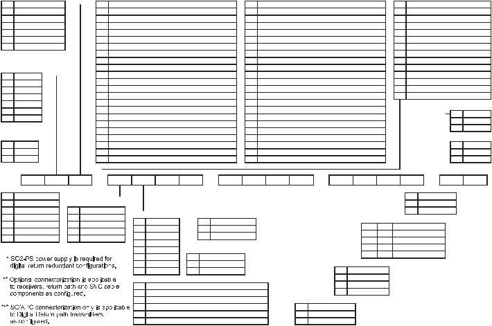
The optional SG2-PS power supply is required to support DS-SG2-DRT-2X/A transmitters in a redundant configuration. The SG2-PS2 and SG2-PS power supplies are interchangeable.
SG 2000 Installation and O peration Manual
O v e r v i e w |
2 - 5 |
Network Monitoring
The optional LIFELINE Status Monitoring System (LL-SG2) enables you to monitor the SG 2000 from a headend or a remote location. The transponder consists of a plug-in module mounted on the main RF board. If you do not employ status monitoring and use redundant receivers and/or transmitters, a manual control board (MCB) occupies the same position on the main RF board.
The entire LIFELINE system includes:
LL-CU control units Are connected to the system at the headend and interrogate each SG 2000 field transponder with FM outbound and inbound transmissions. A variety of outbound and inbound frequencies can be
selected depending on the configuration of the system. The control unit reports this information to the status monitor computer.
Status Monitor
Computer and
Software
LL-SG2-* Field
Installed
Transponders
Includes an IBM -compatible computer that is connected to the control unit (CU) through an RS-232 link. LIFELINE software enables the operator to view measurements taken by the transponders.
Installed in individual field components, this unit interfaces with the CU at the headend. It reports such parameters as: forward amplifier dc current draw, ac and dc voltage, temperature, automatic drive unit (ADU-*) drive voltage, management and control of RF ingress switching, and tamper status.
Configuration
To accommodate unique system criteria, the SG 2000 is shipped as a configured product. Hundreds of variations are available with configurations designed to address numerous system requirements that include:
!Varying RF output configurations
!Forward bandwidth to 750 MHz or 870 MHz
!Forward slope options L, M, H, and U
!Band splits S, J, A, K, E, and M
!Silicon or GaAs technology
!Forward and return path redundancy
#High and low gain options
#Network monitoring
#RF output level control - thermal or automatic
#Multiple return options
Optional hardware features include:
!Analog and digital return transmitter options
!Service cable
#
#
#
#
Surge protection
Chromate or epoxy housing finish SC/APC or FC/APC optical connectors
Ingress switching
SG 2000 Installation and O peration Manual
Manual peration O and Installation 2000 SG
Key |
Bandpass Split |
|
|
Key |
Return Path Configurations (Digital Return) *** |
|
Key |
|
Return Path Configurations (Digital Return) *** |
|
Key |
Return Path Configurations (Analog Return) |
||||||||||||
|
|
|
|
|||||||||||||||||||||
S |
5-40 MHz/52-870 MHz |
|
|
1 |
DS-SG2-DRT-2x/A-1310-FP/SC w/split return |
|
23 |
DS-SG2-DRT/A-1310-DFB/SC w/redundancy |
|
N |
No Transmitter |
|
|
|||||||||||
J |
5-55 MHz/70-870 MHz |
|
|
2 |
DS-SG2-DRT-2x/A-1310-DFB/SC w/split return |
|
24 |
DS-SG2-DRT/A-1550-DFB/SC w/redundancy |
|
D |
SG2-DFBT/* |
|
|
|||||||||||
A |
5-65 MHz/85-870 MHz |
|
|
3 |
DS-SG2-DRT-2x/A-1550-DFB/SC w/split return |
|
25 |
DS-SG2-DRT/A-1510c-DFB/SC w/redundancy |
|
E |
Dual SG2-DFBT/* w/split return |
|||||||||||||
|
|
|
|
|
|
|
|
|
|
|
|
|
|
|
|
|
|
|
|
|
||||
K |
5-42 MHz/54-870 MHz |
4 |
DS-SG2-DRT-2x/A-1510c-DFB/SC w/split return |
26 |
DS-SG2-DRT/A-1530c-DFB/SC w/redundancy |
F |
Dual SG2-DFBT/* w/redundancy |
|||||||||||||||||
E |
5-30 MHz/47-870 MHz |
|
|
5 |
DS-SG2-DRT-2x/A-1530c-DFB/SC w/split return |
|
27 |
DS-SG2-DRT/A-1550c-DFB/SC w/redundancy |
|
I |
SG2-DFBT3/* (2mw) |
|
|
|||||||||||
M |
5-80 MHz/108-870 MHz |
|
|
6 |
DS-SG2-DRT-2x/A-1550c-DFB/SC w/split return |
|
28 |
DS-SG2-DRT/A-1570c-DFB/SC w/redundancy |
|
J |
Dual SG2-DFBT3/* w/split return |
|||||||||||||
|
|
|
|
|
|
|
|
|
7 |
DS-SG2-DRT-2x/A-1570c-DFB/SC w/split return |
|
29 |
DS-SG2-DRT-2x/A-1470c-DFB/SC w/split return |
|
K |
Dual SG2-DFBT3/* w/redundancy |
||||||||
|
|
|
|
|
|
|
|
|
8 |
DS-SG2-DRT/A-1310-FP/SC |
|
30 |
DS-SG2-DRT-2x/A-1490c-DFB/SC w/split return |
|
M |
SG2-FPT/* |
|
|
||||||
|
|
|
|
|
|
|
|
|
9 |
DS-SG2-DRT/A-1310-DFB/SC |
|
31 |
DS-SG2-DRT-2x/A-1590c-DFB/SC w/split return |
|
O |
Dual SG2-FPT/* w/split return |
||||||||
|
|
|
|
|
|
|
|
|
|
|
|
|
|
|
|
|
|
|
|
|
||||
Key |
|
|
|
|
|
10 |
DS-SG2-DRT/A-1550-DFB/SC |
32 |
DS-SG2-DRT-2x/A-1610c-DFB/SC w/split return |
P |
Dual SG2-FPT/* w/redundancy |
|||||||||||||
Tilt |
||||||||||||||||||||||||
|
|
|
|
|
|
|||||||||||||||||||
|
|
|
|
|
|
|
|
|
11 |
DS-SG2-DRT/A-1510c-DFB/SC |
|
33 |
DS-SG2-DRT/A-1470c-DFB/SC |
|
R |
SG2-EIFPT/* |
|
|
||||||
A |
6 dB |
|
|
|||||||||||||||||||||
B |
8 dB |
|
|
|
|
12 |
DS-SG2-DRT/A-1530c-DFB/SC |
|
34 |
DS-SG2-DRT/A-1490c-DFB/SC |
|
S |
Dual SG2-EIFPT/* w/split return |
|||||||||||
|
|
|
|
|
|
|
|
|
13 |
DS-SG2-DRT/A-1550c-DFB/SC |
|
35 |
DS-SG2-DRT/A-1590c-DFB/SC |
|
T |
Dual SG2-EIFPT/* w/redundancy |
||||||||
L |
10 dB |
|||||||||||||||||||||||
|
|
|
|
|
|
|
|
|
14 |
DS-SG2-DRT/A-1570c-DFB/SC |
|
36 |
DS-SG2-DRT/A-1610c-DFB/SC |
|
|
|
|
|
|
|
||||
S |
12.5 dB |
|
|
|
|
|
|
|
||||||||||||||||
H |
14 dB |
|
|
|
|
15 |
DS-SG2-DRT-2x/A-1310-FP/SC w/redundancy split return |
|
37 |
DS-SG2-DRT-2x/A-1470c-DFB/SC w/redundancy split return |
|
|
|
|
|
|
|
|||||||
|
|
|
|
|
|
|
|
|
Key |
Finish |
||||||||||||||
|
|
|
|
|
|
|
|
|
16 |
DS-SG2-DRT-2x/A-1310-DFB/SC w/redundancy split return |
|
38 |
DS-SG2-DRT-2x/A-1490c-DFB/SC w/redundancy split return |
|
|
|
|
|||||||
U |
16 dB |
|
|
|
|
|
|
|
||||||||||||||||
|
|
|
|
|
|
|
|
|
N |
None |
||||||||||||||
|
|
|
|
|
|
|
|
|
17 |
DS-SG2-DRT-2x/A-1550-DFB/SC w/redundancy split return |
|
39 |
DS-SG2-DRT-2x/A-1590c-DFB/SC w/redundancy split return |
|
|
|
|
|||||||
|
|
|
|
|
|
|
|
|
|
|
|
|||||||||||||
|
|
|
|
|
|
|
|
|
|
|
|
|
|
C |
Chromate |
|||||||||
|
|
|
|
|
|
|
|
|
18 |
DS-SG2-DRT-2x/A-1510c-DFB/SC w/redundancy split return |
|
40 |
DS-SG2-DRT-2x/A-1610c-DFB/SC w/redundancy split return |
|
|
|
|
|||||||
|
|
|
|
|
|
|
|
|
|
|
|
|
|
|
|
|
||||||||
|
|
|
|
|
|
|
|
|
|
|
|
|
|
|
|
|
||||||||
|
|
|
|
|
|
|
|
|
19 |
DS-SG2-DRT-2x/A-1530c-DFB/SC w/redundancy split return |
|
41 |
DS-SG2-DRT/A-1470c-DFB/SC w/redundancy |
|
|
|
|
|
|
|
||||
Key |
|
Bandpass |
|
|
|
|
|
|
|
|
|
|
|
|
|
|
|
|
|
Key |
|
|
||
|
|
|
|
20 |
DS-SG2-DRT-2x/A-1550c-DFB/SC w/redundancy split return |
42 |
DS-SG2-DRT/A-1490c-DFB/SC w/redundancy |
|
|
Mounting |
||||||||||||||
75 |
|
750 MHz |
|
|
|
|
|
21 |
DS-SG2-DRT-2x/A-1570c-DFB/SC w/redundancy split return |
|
43 |
DS-SG2-DRT/A-1570c-DFB/SC w/redundancy |
|
|
|
|
X |
Pedestal |
||||||
87 |
|
870 MHz |
|
|
|
|
|
22 |
DS-SG2-DRT/A-1310-FP/SC w/redundancy |
|
44 |
|
|
|
|
|
|
|
|
|
||||
|
|
|
|
DS-SG2-DRT/A-1610c-DFB/SC w/redundancy |
|
|
Y |
Strand |
||||||||||||||||
|
|
|
|
|
|
|
|
|
|
|
|
|
|
|
|
|
|
|
|
|
|
|
|
|
|
|
|
|
|
|
|
|
|
|
|
|
|
|
|
|
|
|
|
|
|
|
|
|
|
SG2 |
|
87 |
|
S |
|
|
S |
|
|
|
|
D |
|
|
|
|
P |
|
T |
|
N |
|
|
|
|
|
S |
|
|
A |
11 |
|
N |
|
|
|
|
|
S |
|
|
|
N |
|
N |
|
N |
|
|
|
|
|
N |
|
X |
|||||||||||||||||||||||||||
|
|
|
|
|
|
|
|
|
|
|
|
|
|
|
|
|
|
|
|
|
|
|
|
|
|
|
|
|
|
|
|
|
|
|
|
|||||||||||||||||||||||||||||||||||||||||||||||
Key |
|
|
|
|
|
|
|
|
|
|
|
|
|
|
|
|
|
|
|
|
|
|
|
|
|
|
|
|
|
|
|
|
|
|
|
|
|
|
|
|
|
|
|
|
|
|
|
|
|
|
|
|
|
|
|
|
|
|
|
|
|
|
|
|
|
|
|
|
|
|
|
|
|
|
|
|
|
|
|
|
|
|
|
RF Configurations |
|
|
|
|
|
|
|
|
|
|
|
|
|
|
|
|
|
|
|
|
|
|
|
|
|
|
|
|
|
|
|
|
|
|
|
|
|
|
|
|
|
|
|
|
|
|
|
|
|
|
|
|
|
|
|
|
|
|
|
|
|
|
|
|
Key |
|
|
Ingress switch |
|
|
|||||||||||
|
|
|
|
|
|
|
|
|
|
|
|
|
|
|
|
|
|
|
|
|
|
|
|
|
|
|
|
|
|
|
|
|
|
|
|
|
|
|
|
|
|
|
|
|
|
|
|
|
|
|
|
|
|
|
|
|
|
|
|
|
|
|
|
|
|
|
|
|||||||||||||||
B |
|
2 Bridger |
|
|
|
|
|
|
|
|
|
|
|
|
|
|
|
|
|
|
|
|
|
|
|
|
|
|
|
|
|
|
|
|
|
|
|
|
|
|
|
|
|
|
|
|
|
|
|
|
|
|
|
|
|
|
|
|
|
|
|
|
|
|
|
|
N |
|
None |
|
|
|||||||||||
C |
|
3 Bridger |
|
|
|
Key |
|
Gain/Hybrid Technology |
|
|
|
|
|
|
|
|
|
|
|
|
|
|
|
|
|
|
|
|
|
|
|
|
|
|
|
|
|
|
|
|
|
|
|
|
|
|
|
|
|
|
|
|
|
|
S |
|
Ingress switches |
|
|
|||||||||||||||||||||||
|
|
|
|
|
|
|
|
|
|
|
|
|
|
|
|
|
|
|
|
|
|
|
|
|
|
|
|
|
|
|
|
|
|
|
|
|
|
|
|
|
|
|
|
|
|
|
|
|
|
|
|
|
|
|||||||||||||||||||||||||||||
|
|
|
|
|
|
|
|
|
|
|
|
|
|
|
|
|
|
|
|
|
|
|
|
|
|
|
|
|
|
|
|
|
|
|
|
|
|
|
|
|
|
|
|
|
|
|
|
|
|
|
|
|
|
|
|
|
|
|
|
|
|
|
|
|
|
|
|
|
|
|
|
|
|
|
|
|
|
|
|
|
|
|
D |
|
4 Bridger |
|
|
|
P |
|
Low/28 dB Silicon |
|
|
|
|
|
|
|
|
|
|
|
|
|
|
|
|
|
|
|
|
|
|
|
|
|
|
|
|
|
|
|
|
|
|
|
|
|
|
|
|
|
|
|
|
|
|
|
|
|
|
|
|
|
|
|
|
|
|||||||||||||||||
|
|
|
|
|
|
|
|
|
Key |
|
Control |
|
|
|
|
Key |
|
|
Connectorization ** |
|
|
|
|
|
|
|
|
|
|
|
|
|
|
|
|
|
|
|
|
|
|
|
|
|
|
|
|
|
|
|
|
|
|
|
||||||||||||||||||||||||||||
E |
|
1 Trunk; 2 Bridger |
|
|
|
R |
|
High/34 dB Silicon |
|
|
|
|
|
|
|
|
|
|
|
|
|
|
|
|
|
|
|
|
|
|
|
|
|
|
|
|
|
Vendor |
Freq |
Status Monitoring |
|
|
|
|||||||||||||||||||||||||||||||||||||||
|
|
|
|
|
|
|
|
|
T |
TCU |
|
|
|
|
S |
|
SC/APC |
|
|
|
|
|
|
|
|
|
|
|
|
|
|
|
|
|
|
|
|
|
||||||||||||||||||||||||||||||||||||||||||||
F |
|
2 Trunk; 2 Bridger |
|
|
|
S |
|
Low/28 dB GaAs |
|
|
|
|
|
|
|
|
|
|
|
|
|
|
|
|
|
|
|
|
|
|
|
|
|
|
|
|
|
|
N |
N |
None |
|
|
|
|
|
|
|
|
|||||||||||||||||||||||||||||||||
|
|
|
|
|
|
|
|
|
|
|
A |
ADU 499.25/S |
|
|
|
|
F |
|
FC/APC |
|
|
|
|
|
|
|
|
|
|
|
|
|
|
|
|
|
|
|
|
|
|
|
|
|
|
|
||||||||||||||||||||||||||||||||||||
G |
|
2 Trunk; 1 Bridger |
|
|
|
T |
|
High/34 dB GaAs |
|
|
|
|
|
|
|
|
|
|
|
|
|
|
|
|
|
|
|
|
|
|
|
|
|
|
|
|
|
|
|
|
|
|
|
|
||||||||||||||||||||||||||||||||||||||
|
|
|
|
|
|
|
|
|
|
|
|
|
|
|
|
|
|
|
|
|
|
|
|
|
|
|
|
|
|
|
|
|
|
|
|
|
|
|
|
|
|
|
|
|
|
|
|
|
||||||||||||||||||||||||||||||||||
|
|
|
|
|
|
|
|
|
|
|
|
|
|
|
|
|
|
|
|
|
|
|
|
|
|
|
|
|
|
|
L |
H |
AMC/Frequency agile |
|
|
|
||||||||||||||||||||||||||||||||||||||||||||||
|
|
|
|
|
|
|
|
|
|
|
|
|
|
|
|
|
|
|
|
|
|
|
|
|
|
|
|
|
|
|
|
|
|
|
|
|
|
|
|
|
|
|
|
|
|
|
|
|
||||||||||||||||||||||||||||||||||
|
|
|
|
|
|
|
|
|
D |
ADU 439.25/S |
|
|
|
|
|
|
|
|
|
|
|
|
|
|
|
|
|
|
|
|
|
|
|
|
|
|
|
|
|
|
|
|
|
|
|
|||||||||||||||||||||||||||||||||||||
|
|
|
|
|
|
|
|
|
|
|
|
|
|
|
|
|
|
|
|
|
|
|
|
|
|
|
|
|
|
|
|
|
|
|
|
|
|
|
|
|
|
|
|
|
|
|
|
|
|
|
|
|
|
|
|
|
|
|
|
|
|
|
|
|
||||||||||||||||||
|
|
|
|
|
|
|
|
|
|
|
|
|
|
|
|
|
|
|
|
|
|
|
|
|
|
|
|
|
|
|
|
|
|
|
|
|
|
|
|
|
|
|
|
|
|
|
|
|
|
|
|
|
|
|
|
|
|
|
|
|
|
T |
J |
TollG/Frequency agile |
|
|
|
|||||||||||||||
|
|
|
|
|
|
|
|
|
|
|
|
|
|
|
|
|
|
|
|
|
|
|
|
|
|
|
|
|
|
E |
ADU 549.00/S |
|
|
|
|
|
|
|
|
|
|
|
|
|
|
|
|
|
|
|
|
|
|
|
|
|
|
|
|
|
|
|
|
|
|
|
||||||||||||||||
|
|
|
|
|
|
|
|
|
|
|
|
|
|
|
|
|
|
|
|
|
|
|
|
|
|
|
|
|
|
|
|
|
|
|
|
|
|
|
|
|
|
|
|
|
|
|
|
|
|
|
|
|
|
|
|
|
|
|
|
|
|
N |
M |
MCB w/SIC |
|
|
|
|
|
|
|
|
||||||||||
|
|
|
|
|
|
|
|
|
|
|
|
|
|
|
|
|
|
|
|
|
|
|
|
|
|
|
|
|
|
H |
ADU 403.25/S |
|
Key |
|
Surge Protection |
|
|
|
|
|
|
|
|
|
|
|
|
|
|
|
|
|
|
|
|
|
|
|
|
|
|
|
|
|||||||||||||||||||
|
|
|
|
|
|
|
|
|
|
|
|
|
|
|
|
|
|
|
|
|
|
|
|
|
|
|
|
|
|
I |
ADU 445.25/S |
|
|
N |
Surge Arrestor |
|
|
|
|
|
|
|
|
|
|
|
|
|
|
|
|
|
|
|
|
|
|
|
|
|
|
|
|
|
|
|
|
|
|
|
|
|||||||||||
|
|
|
|
|
|
|
|
|
|
|
|
|
|
|
|
|
|
|
|
|
|
|
|
|
|
|
|
|
|
|
|
|
|
|
|
|
|
|
|
|
|
|
|
|
|
|
|
|
|
|
|
|
|
|
|
|
|
|
|
|
||||||||||||||||||||||
|
|
|
|
|
|
|
|
|
|
|
|
|
|
|
|
|
|
|
|
|
|
|
|
|
|
|
|
|
|
J |
ADU 325.25/S |
|
|
F |
FTEC BTA Crowbar |
|
|
|
|
|
|
|
|
|
|
|
|
|
|
Key |
|
|
Power Supply |
|
|
|
|
|
|
|
|
|
|
|
|
|
||||||||||||||||
|
|
|
|
|
|
|
|
|
|
|
|
|
|
|
|
|
|
|
|
|
|
|
|
|
|
|
|
|
|
|
|
|
|
|
|
|
|
|
|
|
|
|
|
|
|
|
|
|
|
|
|
|
|
|
|
|
|
|
|
|
S |
Single |
|
|
|
|
|
|
|
|
|
|
|
|
|
|
|
|||||
|
|
|
|
|
|
|
|
|
|
|
|
|
|
|
|
|
|
|
|
|
|
|
|
|
|
|
|
|
|
|
|
|
|
|
|
|
|
|
|
|
|
|
|
|
|
|
|
|
|
|
|
|
|
|
|
|
|
|
|
|
|
|
|
|
|
|
|
|
|
|
|
|
|
|
||||||||
|
|
|
|
|
|
|
|
|
|
|
|
|
|
|
|
|
|
|
|
|
|
|
|
|
|
|
|
|
|
Key |
|
|
|
|
Forward Receivers |
|
|
|
|
|
|
|
|
|
|
|
|
|
D |
Dual |
|
|
|
|
|
|
|
|
|
|
|
|
|
|
|
|||||||||||||||||
|
|
|
|
|
|
|
|
|
|
|
|
|
|
|
|
|
|
|
|
|
|
|
|
|
|
|
|
|
|
|
|
|
|
|
|
|
|
|
|
|
|
|
|
|
|
|
|
|
|
|
|
|||||||||||||||||||||||||||||||
|
|
|
|
|
|
|
|
|
|
|
|
|
|
|
|
|
|
|
|
|
|
|
|
|
|
|
|
|
|
A |
SG2-LR Single |
|
|
|
|
|
|
|
|
|
|
|
|
|
|
|
|
|
|
|
|
|
|
|
|
|
|
R* |
Redundant w/SIC |
|
|
|
|
|
|
|
|
|
|
|
|
|
||||||||||
|
|
|
|
|
|
|
|
|
|
|
|
|
|
|
|
|
|
|
|
|
|
|
|
|
|
|
|
|
|
B |
Dual SG2-LR One Narrowcast/One Broadcast |
|
|
|
|
|
|
|
|
|
|
|
|
|
|
|
|
|
|
|
|
|
|
|
|
|
|
|
|
|
|
|
|
|
|
|
||||||||||||||||
|
|
|
|
|
|
|
|
|
|
|
|
|
|
|
|
|
|
|
|
|
|
|
|
|
|
|
|
|
|
C |
Dual SG2-LR/Dual Receivers w/Redundancy |
|
|
|
|
|
|
Key |
|
|
Service Cable |
|
|
|
|
|
|
|
|
|
|
|
|
|
|
|
|
|
|
|
|
|||||||||||||||||||||
|
|
|
|
|
|
|
|
|
|
|
|
|
|
|
|
|
|
|
|
|
|
|
|
|
|
|
|
|
|
|
|
|
|
|
|
|
|
|
|
|
|
|
|
|
|
|
|
|
|
|
|
|||||||||||||||||||||||||||||||
|
|
|
|
|
|
|
|
|
|
|
|
|
|
|
|
|
|
|
|
|
|
|
|
|
|
|
|
|
|
|
|
|
|
|
|
|
|
|
|
|
|
|
|
|
|
|
|
|
|
|
|
|
|
|
|
|
|
|||||||||||||||||||||||||
|
|
|
|
|
|
|
|
|
|
|
|
|
|
|
|
|
|
|
|
|
|
|
|
|
|
|
|
|
|
D |
Dual SG2-LR/Narrowcast w/Redundancy/One Broadcast |
|
|
C |
6 FiberSer Cable |
|
|
|
|
|
|
|
|
|
|
|
|
|
|
|
|
|
|
|
|
|||||||||||||||||||||||||||
|
|
|
|
|
|
|
|
|
|
|
|
|
|
|
|
|
|
|
|
|
|
|
|
|
|
|
|
|
|
|
|
|
|
|
|
|
|
|
|
|
|
|
|
|
|
|
|
|
|
|||||||||||||||||||||||||||||||||
|
|
|
|
|
|
|
|
|
|
|
|
|
|
|
|
|
|
|
|
|
|
|
|
|
|
|
|
|
|
|
|
|
|
|
|
|
|
|
|
|
|
|
|
|
|
|
|
|
|
|
|
|
|
|
|
|
|
|
|
|
|
|
|
|
|
|
|
|
|
|
|
|
|
|||||||||
|
|
|
|
|
|
|
|
|
|
|
|
|
|
|
|
|
|
|
|
|
|
|
|
|
|
|
|
|
|
N |
None |
|
|
|
|
|
|
|
|
|
|
|
|
|
|
|
|
|
|
N |
None |
|
|
|
|
|
|
|
|
|
|
|
|
|
|
|
|
|
|
|
|
|||||||||||
5-2 Figure notation Configuration |
requirements system suit to configurations of number a in 2000 SG the order can You .cover chassis RF the of portion lower the on label a in noted is configuration notation: configuration the using model sample a illustrates 5-2 Figure |
w e i v r e v O 6 - 2 |
|
shipped The . |
|
|
|
|
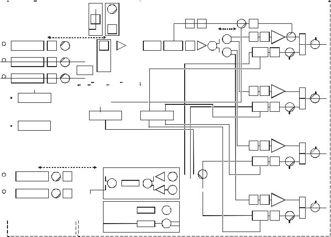
O v e r v i e w |
2 - 7 |
Refer to the current Motorola catalog for option and feature availability.
Forward Path
The multiple receiver functionality of the platform accommodates split-band and/or redundancy applications. A typical split-band configuration has analog signals in the 52 MHz through 550 MHz band feeding one receiver (C location in Figure 2-6). Digital transmissions or narrowcast signals are carried between 450/550 MHz and 870 MHz on another fiber and processed by the second receiver (A location). You can use the optional third receiver (B location) as a back up in the event that the narrowcast receiver loses optical signal input. Automatic path switchover occurs through either the optional status monitoring or manual control-board modules.
Figure 2-6 provides a diagram of the signal flow-path through the SG 2000:
Figure 2-6
Signal flow diagram
SG2 lid |
|
SG2 RF chassis |
|
|||||||||||||||||||||||||||||||||||||||||||||||||||||||||||||||||||||||||||||||||||||||||||||||||||||||||
|
|
|
|
|
|
|
|
|
|
|
|
|
|
|
|
|
|
|
|
|
|
|
|
|
|
|
|
|
|
|
|
|
|
|
|
|
|
|
|
|
|
|
|
|
|
|
|
|
|
|
|
|
|
|
|
|
|
|
|
|
|
|
|
|
|
|
|
|
|
|
|
|
|
|
|
|
|
|
|
|
|
|
|
|
|
|
|
|
|
|
|
|
|
|
|
|
|
|
|
|
|
|
|
|
|
|
|
|
|
|
|
|
|
|
|
|
|
|
|
|
|
|
|
|
|
|
|
|
|
|
|
|
|
|
|
|
|
|
|
|
|
|
|
|
|
|
|
|
|
|
|
|
|
|
|
|
|
|
|
|
|
|
|
|
|
|
|
|
|
|
|
|
|
|
|
|
|
|
|
|
|
|
|
|
|
|
|
|
|
|
|
|
|
|
|
|
|
|
|
|
|
|
|
|
|
|
|
|
|
|
|
|
|
|
|
|
|
|
|
|
|
|
|
|
|
|
|
|
|
SG2-ABJ/P |
|
|
|
|
|
|
|
|
|
|
|
|
|
|
|
|
|
|
|
|
|
|
|
|
SG2-FBS |
|
|
||||||||||||||
|
|
|
|
|
|
|
|
|
|
|
|
|
|
|
|
|
|
|
|
|
|
|
|
|
|
|
|
|
|
|
|
|
|
|
|
|
|
||||||||||||||||
|
|
|
|
|
|
|
|
|
|
|
|
forward |
|
|
|
|
JXP |
|
|
|
|
|
|
|
|
|
|
|
|
|
forward |
|
|
||||||||||||||||||||
|
|
|
|
|
|
|
|
|
|
|
|
A/B |
|
|
|
|
|
|
|
|
|
|
|
|
|
|
|
|
|
|
|
|
|
|
|
|
band |
|
|
||||||||||||||
|
|
|
|
|
|
|
|
|
|
|
|
jumper |
|
|
|
|
|
|
|
|
|
|
|
|
|
|
|
|
|
|
|
|
|
|
|
|
split |
|
|
||||||||||||||
|
|
|
|
|
|
|
|
|
|
|
|
|
|
|
|
|
|
|
|
|
|
|
|
|
|
|
|
|
|
|
|
|
|
|
|
|
|
HP |
|
|
|
|
|
|
|||||||||
|
|
|
|
|
|
|
|
|
|
|
|
|
|
|
|
|
|
|
|
|
|
|
|
|
|
|
|
|
|
|
|
|
|
|
|
|
|
|
|
|
|
|
|
||||||||||
|
|
|
|
|
|
|
|
|
|
TP |
|
|
|
|
|
|
|
|
|
|
|
|
|
|
|
|
|
|
|
|
|
|
|
|
|
|
filter |
|
|
|
|||||||||||||
|
|
|
|
|
|
|
|
|
|
|
|
|
|
|
|
|
|
|
|
|
|
|
|
|
|
|
|
|
|
|
|
|
|
|
|
|
|
|
|
|
|
|
|
|
|
|
|
|
|
||||
|
|
|
|
|
|
|
|
|
|
|
|
|
-1.5 |
|
|
|
|
|
|
|
|
|
|
|
|
|
|
|
|
|
|
|
|
|
|
|
|
|
|
|
|
|
|
|
|
|
|
|
|
|
|||
|
|
|
Receiver C |
|
JXP |
|
|
|
|
|
|
|
|
|
|
|
|
|
|
|
|
|
|
|
|
|
|
JXP |
|
|
|
|
|
|
|
|
|
|
|
|
|
|
|
|
|||||||||
|
|
|
|
|
|
|
|
|
|
TP |
|
|
|
|
|
|
|
|
|
|
|
|
|
|
|
|
|
|
|
|
|
|
|
|
|
|
|
|
|
+15 Lo |
|
|
|||||||||||
|
|
|
|
|
|
|
|
|
|
|
|
|
|
|
|
|
|
|
|
|
|
|
|
|
|
|
|
|
|
|
|
|
|
|
|
|
|
|
|
|
|||||||||||||
|
|
|
|
|
|
|
|
|
|
|
|
|
|
|
|
|
|
|
|
|
|
|
|
|
|
|
|
|
|
|
|
|
|
|
|
|
|
|
|
|
+21.5 Hi |
|
|
||||||||||
|
|
|
Receiver B |
|
JXP |
|
|
|
|
|
|
|
|
|
|
|
|
|
|
|
|
|
|
|
|
|
|
|
|
|
|
|
|
|
|
SG2-FJB/P |
|
|
|||||||||||||||
|
|
|
|
|
|
|
|
|
|
TP |
|
|
|
|
Switch |
|
|
|
|
|
|
forward |
|
|
|||||||||||||||||||||||||||||
|
|
|
|
|
|
|
|
|
|
|
|
|
|
|
|
|
|
|
|
|
|
|
|
|
|
|
|
|
|
|
|
|
|
|
|
|
|
|
|
jumper |
|
|
|||||||||||
|
|
|
Receiver A |
|
JXP |
|
|
|
|
|
|
|
|
|
|
|
|
|
|
|
|
|
|
|
|
|
|
|
|
|
|
|
|
|
|
|
board |
|
|
||||||||||||||
|
|
|
|
|
|
|
|
|
|
|
|
|
|
|
|
|
|
|
|
|
|
|
|
|
|
|
|
|
|
|
|
|
|
|
|
|
|
|
|
|
|
|
|
|
|
|
|
|
|
|
|
|
|
|
|
|
|
|
|
|
|
|
|
|
|
|
|
|
|
|
|
|
|
|
+24 VDC |
|
|
|
|
|
|
|
|
|
|
|
|
|
|
|
|
||||||||||||||||
|
|
|
|
|
|
|
|
|
|
|
|
|
|
|
|
|
|
|
|
|
|
|
|
|
|
|
|
|
|
|
|
|
|
|
|
|
|||||||||||||||||
|
|
|
|
Power supply |
|
|
|
|
|
|
|
|
|
|
|
|
|
|
+5 VDC |
|
|
|
|
|
|
|
|
|
|
|
|
|
|
|
|
||||||||||||||||||
|
|
|
|
|
|
|
|
|
|
|
|
|
|
|
|
|
|
ACV |
|
|
|
|
|
|
|
|
|
|
|
|
|
|
|
|
|||||||||||||||||||
|
|
|
|
|
|
|
|
|
|
|
|
|
|
|
|
|
|
|
|
|
|
|
|
|
|
|
|
|
|
|
|
|
|
|
|
|
|
|
|
|
|
|
|
|
|
|
|
|
|
|
|
|
|
|
|
|
|
|
|
|
|
Data lines |
|
|
|
|
|
|
|
|
|
|
|
|
|
|
|
|
|
|
|
|
|
|
|
|
|
|
|
|
|
|
|
|
|
|
|
|
|
|
|
|
|
|
|||
|
|
|
|
|
|
|
|
|
|
|
|
|
|
|
|
|
|
|
|
|
|
|
|
|
|
Status monitor |
|
|
|
|
|
|
|
|
|||||||||||||||||||
|
|
|
|
|
|
|
|
|
|
|
|
|
|
|
|
|
|
|
|
|
|
|
|
|
|
|
|
|
|||||||||||||||||||||||||
|
|
|
|
Power supply |
|
|
|
|
|
|
|
|
|
|
|
|
|
|
|
|
|
|
|
|
|
|
|
|
|
|
|
|
|
|
|
|
|
|
|
|
|
|
|
|
|
|
|
|
|
|
|
||
|
|
|
|
|
|
|
|
|
|
|
|
|
|
|
|
|
|
|
|
|
|
|
|
|
|
|
|
|
|
|
|
|
|
|
|
|
|
|
|
|
|
|
|
|
|
|
|
||||||
|
|
|
|
|
|
|
|
|
|
|
|
|
|
|
|
|
|
|
|
|
|
|
|
|
|
|
|
|
|
|
|
|
|
|
|
|
|
|
|
|
|
|
|
|
|
|
|
|
|
|
|
|
|
|
|
|
|
|
|
|
|
|
|
|
|
|
|
|
|
|
|
|
|
|
|
|
|
|
|
|
|
|
|
|
|
|
|
|
|
|
|
|
|
|
|
|
|
|
|
|
|
|
|
|
|
|
|
|
|
|
|
|
|
|
|
|
|
|
|
|
|
|
|
|
|
|
|
|
|
|
|
|
|
|
|
|
|
|
|
|
|
|
|
|
|
|
|
|
|
|
|
|
|
|
|
|
|
|
|
|
|
|
|
|
|
|
|
|
|
|
|
|
|
|
|
|
|
|
|
|
|
|
|
|
|
|
|
|
|
|
|
|
|
|
|
|
|
|
|
|
|
|
|
|
|
|
|
|
|
|
|
|
|
|
|
|
|
|
|
|
|
|
|
|
|
|
|
|
|
|
|
|
|
|
|
|
|
|
|
|
|
|
|
|
|
|
|
|
|
|
|
|
|
|
|
|
|
|
|
|
|
|
|
|
|
|
|
|
|
|
|
|
|
|
|
|
|
|
|
|
|
|
|
|
|
|
|
|
|
|
|
|
|
|
|
|
|
|
|
|
|
|
|
|
|
|
|
|
|
|
|
|
|
|
|
|
|
|
|
|
|
|
|
|
|
|
|
|
|
|
|
|
|
|
|
|
|
|
|
|
|
|
|
|
|
|
|
|
|
|
|
|
|
|
|
|
|
|
|
|
|
|
|
|
|
|
|
|
|
|
|
|
|
|
|
|
|
|
|
|
|
ADU |
|
POT |
|
-8.0 |
||
|
|
|
|
|
|
|
|
|
||
|
|
|
|
|
|
|
|
|
Splitter |
|
-2.0 |
|
|
|
-1.5 |
|
|
Splitter |
|
|
|
|
|
|
|
|
|
|
|
|
|
|
SG2-FRB |
|
Attenuator |
|
MDR |
|
|
|
|
|
|
|
|
|
|
|
|
|
|
|||
|
|
|
|
|
|
|
|
|
|
|
-2.0 |
|
|
+ 18.5 |
|
|
|
||||
|
|
|
|
|
||||||
|
@ Min atten |
|
Amplifier |
|
|
|||||
Splitter
Ingress control
|
|
|
|
|
|
|
|
|
|
|
|
|
|
|
|
|
|
|
|
|
|
|
|
|
|
|
|
|
|
|
|
|
|
|
|
|
|
|
|
|
|
|
|
|
|
|
|
|
|
|
|
|
|
|
|
|
|
|
|
|
|
|
|
|
|
|
|
-1.0 |
|
|
|
|
|
|
|
|
SG2-RPM/C |
+8.5 -3.5 |
|
|
|
|
|
-0.5 |
||||||||
|
|
Optical transmitter |
|
|
|
JXP |
|
|
|
|
|
-3.5 |
-2.0 |
-3.5 |
|
|
|
|
|
|
|
|
|
|||||||
|
|
|
|
|
|
|
|
|
|
|
|
|
|
|
|
|
|
|
|
|
|
|||||||||
|
|
|
|
|
|
* |
|
|
|
|
|
|
|
LP filter |
|
|
|
|
|
|
|
|
|
|
|
|
|
|
|
|
|
|
|
TP |
|
|
|
|
|
|
SG2-RPLPF |
|
|
|
|
|
|
|
|
|
|
|
|||||||||
|
|
Optical transmitter |
|
|
|
JXP |
|
|
|
|
|
|
|
|
|
|
|
|
|
|
|
|
|
|
||||||
|
|
|
TP |
** |
|
|
|
|
|
|
|
SG2-RPM/S |
-3.5 |
|
|
|
|
|
|
|
|
|||||||||
|
|
|
|
|
|
|
|
|
|
|
|
|
|
|
|
|
|
|
|
|
|
|
|
|
|
|
|
|
|
|
|
|
|
|
|
|
|
|
|
|
|
|
|
|
|
|
|
LP filter |
|
|
|
|
|
|
|
|
|
|
|
||
|
|
|
|
|
|
|
|
|
|
|
|
|
|
|
|
-2.0 |
|
|
|
|
|
|
|
|
|
|
|
|
||
LP filter
SG2-RPLPF
All forward and return path test points (TP) are -20dB
*5dB
** With second transmitter pad = 5dB; without second transmitter pad = 15dB
JXP |
|
|
-1.0 |
|
|
|
-1.0 |
Amplifier |
Diplex |
|
|
|
|
|
filter |
TP |
|
JXP |
EQ |
+18.5 |
H |
||
|
|||||
|
|
|
|
||
|
|
-0.5 |
-1.0 |
|
|
Ingress |
L |
-0.5 |
|||
JXP |
|||||
|
|||||
-2.0 |
|
|
-0.5 |
|
|
|
|
TP |
|
||
|
|
|
|
||
|
|
Amplifier |
Diplex |
|
|
|
|
|
filter |
TP |
|
JXP |
EQ |
|
H |
||
|
|
||||
|
|
|
|
||
Ingress |
JXP |
L |
|
||
|
|
||||
|
|
|
TP |
|
|
|
|
Amplifier |
Diplex |
|
|
|
EQ |
|
filter |
TP |
|
JXP |
|
H |
|||
|
|
||||
|
|
|
|
||
Ingress |
JXP |
L |
|
||
|
|
||||
|
|
|
TP |
|
|
|
|
Amplifier |
Diplex |
|
|
|
|
|
filter |
TP |
|
JXP |
EQ |
|
H |
||
|
|
||||
|
|
|
|
||
Ingress |
JXP |
L |
|
||
|
|
||||
TP
SG 2000 Installation and O peration Manual
2 - 8 |
O v e r v i e w |
To assess fiber link status, the optical-power monitor circuit is active at all times (even when the receiver is disabled). An integrated optical bulkhead connector and module link status indicators enhance fiber management and reduce troubleshooting time. The receiver module is fully compatible with the status monitor transponder for remote monitoring of key module and link performance parameters.
Several plug-in boards are available to configure the SG 2000 lid board for single, redundant, or narrowcast receiver arrangements. A low-noise pre-amplifier hybrid amplifies the signal to a level suitable for connection to the RF chassis.
An SG2-FRB flatness board, at the input to the RF chassis, compensates for hybrid and accessory response signatures. A variable attenuator circuit enables fine adjustment of the output level, and is driven either by the standard thermal control unit (TCU) or optional ADU pilot automatic gain control (AGC) module to compensate for temperature and input level variations.
The MDR-*/* circuit board provides a fixed linear equalizer for either 750 MHz or 870 MHz. This equalizer comes in numerous values to support various levels of output tilt. The MDR board also compensates for the low frequency roll-off inherent in plug-in diplexers.
A driver-hybrid amplifies the signal to a sufficiently high level to feed up to four power-doubling output stages. These output hybrids can be either conventional silicon or premium gallium arsenide types for even higher station output at low distortion. Plug-in facilities are available ahead of each output stage for individual equalizer boards. These can be installed to customize the tilt for the various ports. At one output, a minus 16 dB directional coupler provides signal to the optional ADU and status-monitor modules. This signal is used only when either or both of these options is installed. It is not necessary to terminate the coupler output when neither option is present.
Minus 20 dB directional test points are available at various points in the signal paths of the node. Because these test points are 75-ohm source impedance, special test probes are not required.
Model JXP-* attenuator pads are used for adjusting signal levels within the signal path. The unit is shipped with JXP-ZX versions installed.
SG 2000 Installation and O peration Manual
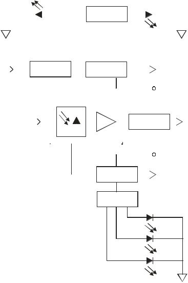
O v e r v i e w |
2 - 9 |
SG2-LR Receiver
The receiver module (SG2-LR) is designed specifically for high performance in the SG 2000. The SG2-LR receiver uses an integrated optical-hybrid photo-detector for improved RF performance over the entire 40 MHz through 870 MHz passband. It is enabled and disabled in response to a signal from the status monitor transponder or manual control board (MCB). This provides excellent isolation, improved reliability, and reduced power consumption when the receiver is used in redundant applications.
Figure 2-7 illustrates a functional block diagram of the SG2-LR receiver:
Figure 2-7
SG2-LR receiver functional diagram
Module enabled
|
|
|
|
|
|
|
|
|
|
|
|
|
|
|
|
|
|
|
|
|
|
|
|
|
|
|
|
|
|
|
|
|
|
|
|
|
|
|
|
|
|
Threshold |
|
|
|
|
|
|
|
|
|
|||||||||||||||||||||||||
|
|
|
|
|
|
|
|
|
|
|
|
|
|
|
|
|
|
|
|
|
|
|
|
|
|
|
|
|
|
|
|
|
|
|
|
|
|
|
comparators |
|
|
|
|
|
|
|
|
|
|
|||||||||||||||||||||||||||
|
|
|
|
|
|
|
|
|
|
|
|
|
|
|
|
|
|
|
|
|
|
|
|
|
|
|
|
|
|
|
|
|
|
|
|
|
|
|
Module |
|
|
|
||||||||||||||||||||||||||||||||||
|
|
|
|
|
|
|
|
|
|
|
|
|
|
|
|
|
|
|
|
|
|
|
|
|
|
|
|
|
|
|
|
|
|
|
|
|
|
|
|
|
|
|
|
|
|
|
|
|
|
|
|
|
|
|
|
|
|
|
|
|
|
|
|
|
|
|
|
|
|
|||||||
|
|
|
|
|
|
|
|
|
|
|
|
|
|
|
|
|
|
|
|
|
|
|
|
|
|
|
|
|
|
|
|
|
|
|
|
|
|
|
|
|
|
|
|
|
|
|
|
|
|
|
|
|
|
|
|
|
|
|
|
|
|
|
|
|
|
|
|
|
|
|||||||
|
|
|
|
|
|
|
|
|
|
|
|
|
|
|
|
|
|
|
|
|
|
|
|
|
|
|
|
|
|
|
|
|
|
|
|
|
|
|
|
|
|
|
|
|
|
|
|
|
|
|
|
|
|
|
|
|
|
|
|
|
|
|
|
|
|
|
|
|
||||||||
|
|
|
+24V |
|
|
|
|
|
|
|
|
|
|
|
|
|
|
|
|
|
|
|
|
|
|
|
|
|
|
|
|
|
|
|
|
|
|
|
|
|
|
|
|
|
|
|
|
|
|
|
|
fault |
|
|
|
|
|
|||||||||||||||||||
|
|
|
|
|
|
|
|
|
|
|
|
|
|
|
|
|
|
|
|
|
|
|
|
|
|
|
|
|
|
|
|
|
|
|
|
|
|
|
|
|
|
|
|
|
|
|
|
|
|
|
|
|
|
|
|
|
|
|
|
|
|
|
|
|
|
|
|
|
|
|
Hybrid current |
|||||
Module |
|
Module enable |
|
|
|
|
|
|
|
|
|
|
|
|
|
|
|
|
Hybrid current |
|
|
|
|
|
|
|||||||||||||||||||||||||||||||||||||||||||||||||||
|
|
|
|
|
|
|
|
|
|
|
|
|
|
|
|
|
|
|
|
|
|
sense signal |
||||||||||||||||||||||||||||||||||||||||||||||||||||||
enable |
|
|
|
logic |
|
|
|
|
|
|
|
|
|
|
|
|
|
|
|
|
|
|
|
|
|
|
|
monitor |
|
|
|
|
|
|
||||||||||||||||||||||||||||||||||||||||||
|
|
|
|
|
|
|
|
|
|
|
|
|
|
|
|
|
|
|
|
|
|
|
|
|
|
|
|
|
|
|
|
(10V/A) |
||||||||||||||||||||||||||||||||||||||||||||
|
|
|
|
|
|
|
|
|
|
|
|
|
|
|
|
|
|
|
|
|
|
|
|
|
|
|
|
|
|
|
|
|
|
|
|
|
|
|
|
|
|
|
|
|
|
|
|
|
|
|
|
|
|
|
|
|
|
|
|
|
|
|
|
|
|
|
|
|
|
|
Hybrid current |
|||||
|
|
|
|
|
|
Optical receiver hybrid |
|
|
|
|
|
|
|
|
|
|
|
|
|
|
|
|
|
|
|
|
test point |
|||||||||||||||||||||||||||||||||||||||||||||||||
|
|
|
|
|
|
|
|
|
|
|
|
|
|
|
|
|
|
|
|
|
|
|
|
|
|
|||||||||||||||||||||||||||||||||||||||||||||||||||
|
|
|
|
|
|
|
|
|
|
|
|
|
(1.0 V/A) |
|||||||||||||||||||||||||||||||||||||||||||||||||||||||||||||||
|
|
Optical |
|
|
|
|
|
|
|
|
|
|
|
|
|
|
|
|
|
|
|
|
|
|
|
|
|
|
|
|
|
|
|
|
|
|
|
|
|
|
|
|
|
|
|
|
|
|
|
|
|
|
|
|
|
|
|
|
|
|
|
|
|
|
|
|
|
|
|
|
|
|
RF |
|||
|
|
|
|
|
|
|
|
|
|
|
|
|
|
|
|
|
|
|
|
|
|
|
|
|
|
|
|
|
|
|
|
|
|
|
|
|
|
|
|
|
|
|
|
|
|
|
|
|
|
|
|
|
|
|
|
|
|
|
|
|
|
|
|
|
||||||||||||
|
|
|
|
|
|
|
|
|
|
|
|
|
|
|
|
|
|
|
|
|
|
|
|
|
|
|
|
|
|
|
|
|
|
|
|
|
|
|
|
|
|
|
|
|
|
|
|
|
|
|
|
|
|
|
|
|
|
|
|
|
|
|
|
|
||||||||||||
|
|
|
|
|
|
|
|
|
|
|
|
|
|
|
|
|
|
|
|
|
|
|
|
|
|
|
|
|
|
|
|
|
|
|
|
|
|
|
|
|
|
|
|
|
|
|
|
|
|
|
|
|
|
|
|
|
|
|
|
|||||||||||||||||
|
|
|
|
|
|
|
|
|
|
|
|
|
|
|
|
|
|
|
|
|
|
|
|
|
|
|
|
|
|
|
|
|
|
|
|
|
|
|
|
|
|
|
|
|
|
|
|
|
|
|
|
Matching |
|
|
|
|
||||||||||||||||||||
|
|
input |
|
|
|
|
|
|
|
|
|
|
|
|
|
|
|
|
|
|
|
|
|
|
|
|
|
|
|
|
|
|
|
|
|
|
|
|
|
|
|
|
|
|
|
|
|
|
|
|
|
|
|
network |
|
|
|
|
output |
|||||||||||||||||
|
|
|
|
|
|
|
|
|
|
|
|
|
|
|
|
|
|
|
|
|
|
|
|
|
|
|
|
|
|
|
|
|
|
|
|
|
|
|
|
|
|
|
|
|
|
|
|
|
|
|
|
|
|
|
|
|
|
|
|
|
|
|
|
|
|
|
|
|
||||||||
|
|
|
|
|
|
|
|
|
|
|
|
|
|
|
|
|
|
|
|
|
|
|
|
|
|
|
|
|
|
|
|
|
|
|
|
|
|
|
|
|
|
|
|
|
|
|
|
|
|
|
|
|||||||||||||||||||||||||
|
|
|
|
|
|
|
|
|
|
|
|
|
|
|
|
|
|
|
|
|
|
|
|
|
|
|
|
|
|
|
|
|
|
|
|
|
|
|
|
|
|
|
|
|
|
|
|
|
|
|
|
|
|
|
|
|
|
|
|
|
|
|
|
|
|
|
|
|
|
|
|
|
|
|
|
|
|
|
|
|
|
|
|
|
|
|
|
|
|
|
|
|
|
|
|
|
|
|
|
|
|
|
|
|
|
|
|
|
|
|
|
|
|
|
|
|
|
|
|
|
|
|
|
|
|
|
|
|
|
|
|
|
|
|
|
|
|
|
|
|
|
|
|
|
|
|
|
Optical power |
|||||
|
|
|
|
|
|
|
|
|
|
|
|
|
|
|
|
|
|
|
|
|
|
|
|
|
|
|
|
|
|
|
|
|
|
|
|
|
|
|
|
|
|
|
|
|
|
|
|
|
|
|
|
|
|
|
|
|
|
|
|
|
|
|
|
|
|
|
|
|
|
|
||||||
|
|
|
|
|
|
|
|
|
|
|
|
|
|
|
|
|
|
|
|
|
|
|
|
|
|
|
|
|
|
|
|
|
|
|
|
|
|
|
|
|
|
|
|
|
|
|
|
|
|
|
|
|
|
|
|
|
|
|
|
|
|
|
|
|
|
|
|
|
|
|
||||||
|
|
|
|
|
|
|
|
|
|
|
|
|
|
|
|
|
|
|
|
|
|
|
|
|
|
|
|
|
|
|
|
|
|
|
|
|
|
|
|
|
|
|
|
|
|
|
|
|
|
|
|
|
|
|
|
|
|
|
|
|
|
|
|
|
|
|
|
|
|
|
||||||
|
|
|
|
|
|
|
|
|
|
|
|
|
|
|
|
|
|
|
|
|
|
|
|
|
|
|
|
|
|
|
|
|
|
|
|
|
|
|
|
|
|
|
|
|
|
|
|
|
|
|
|
|
|
|
|
|
|
|
|
|
|
|
|
|
|
|
|
|
|
|
||||||
|
|
|
|
|
|
|
|
|
|
|
|
|
|
|
|
|
|
|
|
|
|
|
|
|
|
|
|
|
|
|
|
|
|
|
|
|
|
|
|
|
|
|
|
|
|
|
|
|
|
|
|
|
|
|
|
|
|
|
|
|
|
|
|
|
|
|
|
|
|
|
||||||
|
|
|
|
|
|
|
|
|
|
|
|
|
|
|
|
|
|
|
|
|
|
|
|
|
|
|
|
|
|
|
|
|
|
|
|
|
|
|
|
|
|
|
|
|
|
|
|
|
|
|
|
|
|
|
|
|
|
|
|
|
|
|
|
|
|
|
|
|
|
|
||||||
|
|
|
|
|
|
|
|
|
|
|
|
|
|
|
|
|
|
|
|
|
|
|
|
|
|
|
|
|
|
|
|
|
|
|
|
|
|
|
|
|
|
|
|
|
|
|
|
|
|
|
|
|
|
|
|
|
|
|
|
|
|
|
|
|
|
|
|
|
|
|
|
test point |
||||
|
|
|
|
|
|
|
|
|
|
|
|
|
|
|
|
|
|
|
|
|
|
|
|
|
|
|
|
|
|
|
|
|
|
|
|
|
|
|
|
|
|
|
|
|
|
|
|
|
|
|
|
|
|
|
|
|
|
|
|
|
|
|
|
|
|
|
|
|
|
|
|
|||||
|
|
|
|
|
|
|
|
|
|
|
|
|
|
|
|
|
|
|
|
|
|
|
|
|
|
|
|
|
|
|
|
|
|
|
|
|
|
|
|
|
|
|
|
|
|
|
|
|
|
|
|
|
|
|
|
|
|
|
|
|
|
|
|
|
|
|
|
|
|
|
|
(1 V/mW) |
||||
|
|
|
|
|
|
|
|
|
|
|
|
|
|
|
|
|
|
|
|
|
|
|
|
|
|
|
|
|
|
|
|
|
|
|
|
|
|
|
|
|
|
|
|
|
|
|
Optical power |
|
|
|
Optical power |
|||||||||||||||||||||||||
|
|
|
|
|
|
|
|
|
|
|
|
|
|
|
|
|
|
|
|
|
|
|
|
|
|
|
|
|
|
|
|
|
|
|
|
|
|
|
|
|
|
|
|
|
|
|
|
|
|
|
|
|
monitor |
|
|
|
sense signal |
|||||||||||||||||||
(1 V/mW)
Threshold comparators
Low |
Normal |
High |
SG 2000 Installation and O peration Manual
2 - 1 0 |
O v e r v i e w |
Analog Return Path
Similar to the multiple optical receivers, the dual return-path optical transmitters also have split-return or redundant functionality. In split-return applications two of the four RF return signals are fed to one optical transmitter while the remaining two return signals are fed to the second transmitter.
Signal levels are adjusted in each return path using model JXP-* attenuator pads. Units are shipped with a JXP-5 (5 dB) attenuator pad at the input position of each installed transmitter. If only one transmitter is in the unit, there will be a 15 dB pad at the second transmitter input position to serve as a termination. Ingress switching is also an available option. If ingress switches are not used, JXP-2 pads are installed.
When configured for redundancy, both return lasers are active and transmit the combined RF return signals simultaneously. Or, they can be activated independently using the status monitor transponder or the MCB. In the event of path failure, return path redundancy is accomplished at the headend or the receive site by switching to the alternate or active return fiber.
Analog Return Transmitters
Five optical analog return transmitters are available to meet the needs of most return applications. Table 2-1 identifies and describes the five analog return transmitters:
Table 2-1
Analog return transmitters
Model Description
SG2-IFPT/* Uses an isolated, uncooled, Fabry-Perot laser operating at 400 µW. It carries a full 35 MHz of digital data or up to two video channels.
SG2-FPT/* Uses a non-isolated, uncooled, Fabry-Perot laser operating at 400 µW. It carries a full 35 MHz of digital data or up to two video channels.
SG2-DFBT/* Uses an uncooled, isolated DFB laser operating at 1 mW for improved link performance. It carries a full 35 MHz of digital data or up to two video channels.
SG2-DFBT/3 Uses an uncooled, isolated DFB laser operating at 2 mW for improved link performance. It carries a full 35 MHz of digital data or up to two video channels.
SG2-EIFPT/* Uses an uncooled, enhanced, and isolated Fabry-Perot laser operating at 1 mW for improved link performance. It carries a full 35 MHz of digital data or up to two video channels.
The transmitters include thermal compensation circuitry to minimize the change in received optical and RF signal level at the headend as the node temperature varies. To reduce power consumption and enhance reliability, the transmitters can be enabled and disabled in response to a signal from the status monitor transponder or the MCB. An integrated optical bulkhead connector and module status indicators enhance fiber management and reduce troubleshooting time. For remote monitoring of key module performance parameters, the return modules are fully compatible with the status-monitor transponder.
SG 2000 Installation and O peration Manual
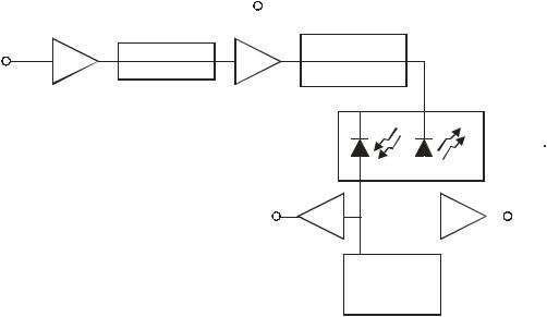
O v e r v i e w |
2 - 1 1 |
Figure 2-8 illustrates a functional block diagram of the SG2 transmitter:
Figure 2-8
SG2 transmitter block diagram
|
|
Hybrid |
|
||
|
|
current |
|
||
|
|
test |
|
||
|
|
|
|
|
|
|
|
|
|
|
|
RF |
|
|
|
JXP |
|
Thermal |
|
||||
|
|
factory calibration |
|
||
input |
compensation |
|
|
Laser |
|
|
|
only |
|||
|
|
|
|
diode |
|
|
|
|
|
|
|
|
|
|
|
|
|
|
|
|
|
|
module |
Fiber output
|
|
|
|
Optical |
|
Laser |
|
power |
|
current |
|
test |
|
test |
|
Laser bias control
SG 2000 Installation and O peration Manual
2 - 1 2 |
O v e r v i e w |
Digital Return Path
The digital return transmitter series (DS-SG2-DRT*) converts a broadband analog RF return-path signal into digital optical signals with 10-bit resolution.
The transmitters used for digital return applications are divided into two families: DS-SG2-DRT/A and DS-SG2-DRT-2X/A.
Seven digital return transmitters per family are available to meet the needs of most digital return applications.
Table 2-2 identifies the fourteen optical digital return transmitters:
Table 2-2
Digital return transmitters
DS-SG2-DRT/A
DS-SG2-DRT/A-1310 FP DS-SG2-DRT/A-1310 DFB DS-SG2-DRT/A-1470 DFB DS-SG2-DRT/A-1490 DFB DS-SG2-DRT/A-1550 DFB DS-SG2-DRT/A-1510c (2) DFB DS-SG2-DRT/A-1530c DFB DS-SG2-DRT/A-1550c DFB DS-SG2-DRT/A-1570c DFB DS-SG2-DRT/A-1590 DFB DS-SG2-DRT/A-1610 DFB
DS-SG2-DRT-2X/A
DS-SG2-DRT-2X (1)/A-1310 FP DS-SG2-DRT-2X/A-1310 DFB DS-SG2-DRT-2X/A-1470 DFB DS-SG2-DRT-2X/A-1490 DFB DS-SG2-DRT-2X/A-1550 DFB DS-SG2-DRT-2X/A-1510c DFB DS-SG2-DRT-2X/A-1530c DFB DS-SG2-DRT-2X/A-1550c DFB DS-SG2-DRT-2X/A-1570c DFB DS-SG2-DRT-2X/A-1590 DFB DS-SG2-DRT-2X/A-1610 DFB
(1)2X in the model number denotes time division multiplexing (TDM)
(2)c in the model number denotes coarse wave division multiplexing (CWDM)
To prepare for an anticipated increase in return traffic, provisioning for CWDM is built into the transmitters. The CWDM option consists of lasers at predefined wavelengths. This option is available to support multiplexing in the optical domain, using eight-wavelength wave division multiplexing (WDM) in the DS-SG2-DRT/A-15XX DFB and DS-SG2-DRT-2X/A-15XX DFB windows.
DS-SG2-DRT/A
The DS-SG2-DRT/A digitizes a single analog 5-42 MHz return path signal to produce a 1.6 Gbps data stream. This data stream is then routed to a digital laser for transmission to a corresponding digital return receiver. The node can be configured with one or two DS-SG2-DRT/A transmitters, with dual transmitters providing redundancy. In conjunction with these transmitters, the node must also be configured with the SG2 Return Path Module/Combined (SG2-RPM/C). The return signals from all four ports are combined and fed to the optical transmitters.
SG 2000 Installation and O peration Manual
O v e r v i e w |
2 - 1 3 |
When configured for redundancy, both return transmitters are normally active and transmit the combined RF return signal simultaneously. In the event of path failure, continuity of service is accomplished at the headend or the receiver site by switching to the alternate or active return fiber.
Signal levels are adjusted in each return path using Model JXP-* attenuator pads. Units are shipped with a JXP-5 (5 dB) attenuator pad at the input position of each installed transmitter. If only one transmitter is installed, there will be a 15 dB pad at the second transmitter input position to serve as a termination.
DS-SG2-DRT-2X/A
The DS-SG2-DRT-2X/A has two separate RF inputs. The transmitter digitizes these two independent analog 5-42 MHz return-path signals to produce two 1.25 Gbps data streams. These two data streams are then multiplexed to create a single 2.5 Gbps data stream that is then routed to a digital laser for transmission to a corresponding digital return receiver. In conjunction with these transmitters, the node must also be configured with the SG2 Return Path Module/Split (SG2-RPM/S). Return signals from two of the four node ports are fed to one RF input of the transmitter while the remaining two return signals are fed to the second RF input. The signal paths for both inputs are explained in more detail in Section 5, “Operation”.
Signal levels are adjusted in each return path using Model JXP-* attenuator pads. The transmitter gets one of its RF signals automatically when the unit is plugged into its appropriate slot. The second RF signal comes through a special adapter from the adjacent connector, which is normally available for installing a redundant transmitter. Therefore, the units are shipped with two JXP-5 attenuator pads at the input positions.
Ingress control switching is an available option with any return transmitter configuration. If ingress switches are not used, JXP-2 pads are installed in each ingress switch position on the main RF board.
The node can be configured with one or two DS-SG2-DRT-2X/A transmitters, with dual transmitters providing redundancy. The redundancy configuration is explained in more detail in Section 5, “Operation”.
Section 5, “Operation,” also provides detailed information and block diagrams for each series of digital transmitters.
SG 2000 Installation and O peration Manual
2 - 1 4 |
O v e r v i e w |
Level Control
The gain of hybrid IC amplifiers varies with temperature. In addition, changes in system channel loading and/or splices in the fiber link can change the level of the received signal.
The standard TCU board compensates for anticipated hybrid gain changes by sensing housing temperature and signaling needed changes to the RF attenuator.
The ADU board, an optional plug-in module, monitors the amplitude of a selected pilot frequency. The pilot frequency is an available analog television channel not scrambled by the sync suppression method. Any changes in amplitude are fed back to the RF attenuator that makes appropriate corrections.
The input to the ADU contains a JXP-* pad. The factory-installed value of this pad is 6 dB (JXP-6) for bridger level outputs and 0 dB (JXP-ZX) for trunk level outputs. Under normal conditions, it should not be changed.
Options and Accessories
Table 2-3 provides a list of options and accessories for the SG 2000:
Table 2-3
Options and accessories
Model |
Description |
Function |
ADU-* |
Automatic drive |
This option automatically adjusts gain by monitoring changes |
|
unit |
in the level of the selected pilot carrier. Either an ADU or TCU |
|
|
must be installed. |
TCU |
Thermal control |
The TCU controls amplifier gain for changes in hybrid gain at |
|
unit |
the sensed temperature. |
JXP-*A |
Fixed |
Attenuator pads are used to adjust amplifier levels and are |
|
attenuator |
available in 1 dB steps from 1 through 24 dB. The appropriate |
|
|
value must be installed. |
JXP-ZX |
0 dB attenuator |
This attenuator is used in place of JXP-*A pads when no |
|
|
attenuation is needed. |
FTEC |
Crowbar |
The FTEC is an electronic crowbar/surge protector that can be |
|
overvoltage |
used to replace the existing 230-volt gas discharge surge |
|
protection |
protector. |
LL-SG2 |
LIFELINE |
This module enables the system operator to monitor the SG2 |
|
module |
from a remote location. See Section 5, “Operation” for |
|
|
parameters monitored. Several frequencies are available. See |
|
|
the product catalog for additional information. |
GFAL |
Test probe |
This probe is used to evaluate node performance. |
F/JXP |
Injection probe |
This probe is used to inject a signal for test purposes. |
SG 2000 Installation and O peration Manual
O v e r v i e w |
2 - 1 5 |
Model |
Description |
Function |
SG2-MCB |
Manual control |
This board locally controls the ingress switch and |
|
board |
receiver/transmitter A/B redundant switching if the node is not |
|
|
equipped with status monitoring. |
SG2-SB/* |
Strand bracket |
Bracket for hanging a strand mounted node. |
SG2-PS |
Power supply |
Provides the + 24 V and + 5 V dc supply to the station. It has an |
|
|
extended voltage range and is power-factor corrected. |
SG2-PS2 |
Power supply |
Provides the + 24 V and + 5 V dc supply to the station. |
SG2- |
Service cable |
A 6-fiber service cable that is available with SC/APC or |
SERCAB/* |
|
FC/APC connectors. |
SG2-FE- |
Forward |
Used to increase output tilt at one or more ports in a 750 MHz |
*/750 |
equalizers |
system. They are available in 1 dB increments from 2 dB |
|
|
through 6 dB. |
SG2-FE- |
Forward |
Used to increase output tilt at one or more ports in an 870 |
*/870 |
equalizers |
MHz system. They are available in 1 dB increments from 2 dB |
|
|
through 6 dB. |
SG2-IS |
Ingress switch |
This switch enables the operator to troubleshoot without |
|
|
shutting down the return path. It requires the use of either the |
|
|
LL-SG2/* or the SG2-MCB. |
SG2-LR |
Lightwave |
This receiver converts the received optical signal to |
|
receiver |
broadband RF. |
DS-SG2-DRRB Digital return |
This board provides the redundant input to a |
|
|
redundancy |
DS-SG2-DRT/A-2X digital return transmitter. One DRRB is |
|
board |
used for each -2X transmitter. |
SG2-* |
Analog return |
Table 2-1 identifies and describes the five optical analog |
|
transmitters |
return-path transmitters. |
DS-SG2-DRT* |
Digital return |
Table 2-2 identifies all models of the optical digital return-path |
|
transmitters |
transmitters. Section 5, “Operation,” provides detailed |
|
|
information and block diagrams for each series of digital |
|
|
transmitters. |
SG 2000 Installation and O peration Manual
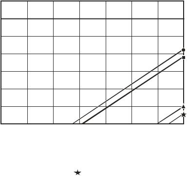
2 - 1 6 |
O v e r v i e w |
Gain Selection
Figures 2-9 through 2-13 illustrate SG 2000 gain and tilt selection charts based on frequency and channel load options.
To use the gain option selection charts, Figures 2-9 and 2-10, first find the point on the left hand axis that corresponds to the expected optical input power at the node. Move across this horizontal line to the right until it intersects a vertical line corresponding to the desired RF output level.
If this intersection is above and to the left of the diagonal “lo gain limit” line for the channel loading under consideration, the low-gain option will give optimum performance with minimum padding. If the intersection lies between the “lo gain limit” and “hi gain limit” lines, then choose the high-gain option. Operation at a combination of input and output levels below and to the right of the “hi gain limit” line is not possible.
Figure 2-9 illustrates the gain option selection chart for 750 MHz:
Figure 2-9
Optical input versus 750 MHz gain
750 MHz Gain Selection
Optical input (dBm)
2
1
0
-1
-2
-3
-4
-5
38 |
40 |
42 |
44 |
46 |
48 |
50 |
52 |
Bridger output level (dBmV), 750 MHz equivalent (Trunk output level is 10 dB lower)
Lo gain limit, 94 ch  Hi gain limit, 94 ch
  Lo gain limit, 77 ch
 Hi gain limit, 77 ch
Figure 2-9 gives the output level at 750 MHz. For a system loaded with analog channels to
550 MHz, the actual level at 550 MHz is 3.5 dB lower with the standard overall tilt of 12.5 dB. For the low tilt of 10 dB, the reduction at 550 MHz is 3.0 dB. For the high tilt of 14 dB, the 550 MHz level is 4.0 dB lower than at 750 MHz.
SG 2000 Installation and O peration Manual
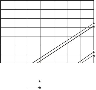
O v e r v i e w |
2 - 1 7 |
Figure 2-10 illustrates the gain option selection chart for 870 MHz:
Figure 2-10
Optical input versus 870 MHz gain
870 MHz Gain Selection
Optical input (dBm)
2
1
0
-1
-2
-3
-4
-5
38 |
40 |
42 |
44 |
46 |
48 |
50 |
52 |
Bridger output level (dBmV), 870 MHz equivalent (Trunk output level is 10 dB lower)
Lo gain limit, 110 ch
Hi gain limit, 110 ch 
Lo gain limit, 94 ch 

Hi gain limit, 94 ch
Figure 2-10 gives the output level at 870 MHz. For a system loaded with analog channels to
750 MHz, the actual level at 750 MHz is 1.7 dB lower with the standard overall tilt of 11.5 dB. For the low tilt of 9.0 dB, the reduction at 750 MHz is 13 dB. For the high tilt of 14 dB, the 750 MHz level is 2.1 dB lower than at 870 MHz.
For a system loaded with analog channels to 650 MHz, the actual level at 650 MHz is 3.1 dB lower than the given 870 MHz level with the standard overall tilt of 11.5 dB. For the low tilt of 9.0 dB, the reduction at 650 MHz is 2.4 dB. For the high tilt of 14 dB, the 650 MHz level is 3.8 dB lower than at 870 MHz.
SG 2000 Installation and O peration Manual
Loading...