


Professional Digital Two-Way Radio System
MOTOTRBO™ Repeater
Basic Service Manual
DR 3000 Repeater
M
DR 3000
UHF Range 1
MOTOTRBO™ Repeater
Basic Service Manual
6866576D03-A

Foreword
This manual covers all models of the MOTOTRBO Repeater, unless otherwise specified. It includes all the information necessary to maintain peak product performance and maximum working time, using levels 1 and 2 maintenance procedures. This level of service goes down to the board replacement level and is typical of some local service centers, Motorola Authorized Dealers, self-maintained customers, and distributors.
For details on repeater operation or component-level troubleshooting, refer to the applicable manuals available separately.
Product Safety and RF Exposure Compliance
Before using this product, read the operating instructions ! for safe usage contained in the Product Safety and RF
C a u t i o n Exposure booklet enclosed with your product.
ATTENTION!
This repeater is restricted to occupational use only to satisfy ICNIRP/FCC RF energy exposure requirements. Before using this product, read the RF energy awareness information and operating instructions in the Product Safety and RF Exposure booklet enclosed with your product (Motorola Publication part number 6866537D37) to ensure compliance with RF energy exposure limits.
For a list of Motorola-approved antennas, and other accessories, visit the following web site which lists approved accessories: http://www.motorola.com/governmentandenterprise
Computer Software Copyrights
The Motorola products described in this manual may include copyrighted Motorola computer programs stored in semiconductor memories or other media. Laws in the United States and other countries preserve for Motorola certain exclusive rights for copyrighted computer programs, including, but not limited to, the exclusive right to copy or reproduce in any form the copyrighted computer program. Accordingly, any copyrighted Motorola computer programs contained in the Motorola products described in this manual may not be copied, reproduced, modified, reverse-engineered, or distributed in any manner without the express written permission of Motorola. Furthermore, the purchase of Motorola products shall not be deemed to grant either directly or by implication, estoppel, or otherwise, any license under the copyrights, patents or patent applications of Motorola, except for the normal non-exclusive license to use that arises by operation of law in the sale of a product.
Document Copyrights
No duplication or distribution of this document or any portion thereof shall take place without the express written permission of Motorola. No part of this manual may be reproduced, distributed, or transmitted in any form or by any means, electronic or mechanical, for any purpose without the express written permission of Motorola.
Disclaimer
The information in this document is carefully examined, and is believed to be entirely reliable. However, no responsibility is assumed for inaccuracies. Furthermore, Motorola reserves the right to make changes to any products herein to improve readability, function, or design. Motorola does not assume any liability arising out of the applications or use of any product or circuit described herein; nor does it cover any license under its patent rights nor the rights of others.
Trademarks
MOTOROLA and the Stylized M logo are registered in the U.S. Patent & Trademark Office. All other product or service names are the property of their respective owners.
© 2007 by Motorola, Inc. All rights reserved.

iii
Document History
The following major changes have been implemented in this manual since the previous edition:
Edition |
|
Description |
Date |
|
|
|
|
6866576D03-A |
Initial Release |
|
Feb. 2007 |
|
|
|
|
6866576D03-A |
February 21, 2007 |

iv
Notes
February 21, 2007 |
6866576D03-A |

Table of Contents |
v |
Table of Contents
Foreword......................................................................................................... |
|
ii |
|
Product Safety and RF Exposure Compliance ............................................................................................ |
ii |
||
Computer Software Copyrights ................................................................................................................... |
ii |
||
Document Copyrights.................................................................................................................................. |
ii |
||
Disclaimer.................................................................................................................................................... |
|
ii |
|
Trademarks ................................................................................................................................................. |
|
ii |
|
Document History ........................................................................................ |
iii |
||
Chapter 1 |
Introduction ......................................................................... |
1-1 |
|
1.1 |
Notations Used in This Manual.................................................................................................... |
1-1 |
|
1.2 |
Repeater Description ................................................................................................................... |
1-1 |
|
1.3 |
MOTOTRBO Repeater Model Numbering Scheme..................................................................... |
1-2 |
|
1.4 |
UHF1 High Power MOTOTRBO Repeater (403-470 MHz) Model Chart..................................... |
1-3 |
|
1.5 |
Specifications............................................................................................................................... |
1-4 |
|
Chapter 2 |
Test Equipment and Service Aids ..................................... |
2-1 |
|
2.1 |
Recommended Test Equipment .................................................................................................. |
2-1 |
|
2.2 |
Service Aids................................................................................................................................. |
2-2 |
|
2.3 |
Programming Cables .................................................................................................................. |
2-2 |
|
Chapter 3 |
Transceiver Performance Testing ..................................... |
3-1 |
|
3.1 |
General ........................................................................................................................................ |
3-1 |
|
3.2 |
Setup ........................................................................................................................................... |
|
3-1 |
Chapter 4 |
Repeater Tuning and Programming .................................. |
4-1 |
|
4.1 |
Introduction .................................................................................................................................. |
4-1 |
|
4.2 |
Customer Programming Software Setup ..................................................................................... |
4-1 |
|
4.3 |
Repeater Tuning Setup................................................................................................................ |
4-2 |
|
Chapter 5 |
Disassembly/Reassembly Procedures ............................. |
5-1 |
|
5.1 |
Introduction .................................................................................................................................. |
5-1 |
|
5.2 |
Preventive Maintenance .............................................................................................................. |
5-1 |
|
|
5.2.1 |
Inspection ........................................................................................................................ |
5-1 |
|
5.2.2 |
Cleaning Procedures ....................................................................................................... |
5-1 |
5.3 |
Safe Handling of CMOS and LDMOS Devices............................................................................ |
5-2 |
|
5.4 |
Repair Procedures and Techniques — General.......................................................................... |
5-3 |
|
5.5 |
Disassembling and Reassembling the Repeater — General ...................................................... |
5-4 |
|
6866576D03-A |
February 21, 2007 |

vi |
|
|
Table of Contents |
|
|
|
|
||
5.6 |
Disassembly Procedures — Detailed .......................................................................................... |
5-4 |
||
|
5.6.1 |
Disassembly of Cover...................................................................................................... |
5-4 |
|
|
5.6.2 |
Disassembly of Repeater Indicator Board ....................................................................... |
5-5 |
|
|
5.6.3 |
Disassembly of Fan ......................................................................................................... |
5-6 |
|
|
5.6.4 |
Removing Transmit Radio ............................................................................................... |
5-7 |
|
|
|
5.6.4.1 Removing Thermal Pad and Heatsink .............................................................. |
5-8 |
|
|
5.6.5 Removing Receive Radio, Power Supply and Connector Board Assembly .................... |
5-8 |
||
|
|
5.6.5.1 |
Disassembly of Receive Radio ....................................................................... |
5-10 |
|
|
5.6.5.2 |
Disassembly of Connector Board Assembly................................................... |
5-10 |
|
|
5.6.5.3 |
Disassembly of Power Supply ........................................................................ |
5-10 |
5.7 |
Transmit and Receive Radio Disassembly — Detailed ............................................................. |
5-11 |
||
|
5.7.1 Transceiver Board and Receiver Board Removal ......................................................... |
5-11 |
||
5.8 |
Transmit and Receive Radio Reassembly — Detailed .............................................................. |
5-14 |
||
|
5.8.1 Transceiver Board and Receiver Board Reassembly.................................................... |
5-15 |
||
|
5.8.2 Thermal Pad Replacement Procedure .......................................................................... |
5-19 |
||
|
5.8.3 Reassembly of Receive Radio, Power Supply and Connector Board Assembly........... |
5-21 |
||
|
|
5.8.3.1 |
Reassembly of Power Supply ......................................................................... |
5-21 |
|
|
5.8.3.2 |
Reassembly of Receive Radio........................................................................ |
5-21 |
|
|
5.8.3.3 |
Reassembly of Connector Board Assembly ................................................... |
5-21 |
|
|
5.8.3.4 Reassembly of the Receive Bracket Assembly to the Enclosure ................... |
5-21 |
|
|
5.8.4 |
Reassembly of Transmit Radio...................................................................................... |
5-22 |
|
|
|
5.8.4.1 Replacing the Thermal Pad and Heatsink ...................................................... |
5-22 |
|
|
|
5.8.4.2 Reassembly of the Transmit Bracket Assembly to the Enclosure .................. |
5-22 |
|
|
5.8.5 |
Reassembly of Fan........................................................................................................ |
5-23 |
|
|
5.8.6 |
Reassembly of Repeater Indicator Board...................................................................... |
5-23 |
|
|
5.8.7 |
Reassembly of Cover .................................................................................................... |
5-23 |
|
5.9 |
Repeater Exploded Mechanical Views and Parts Lists.............................................................. |
5-24 |
||
5.10 |
Torque Chart.............................................................................................................................. |
|
5-27 |
|
Chapter 6 |
Basic Troubleshooting ....................................................... |
6-1 |
|
6.1 |
Introduction .................................................................................................................................. |
6-1 |
|
|
6.1.1 High Power RF Precaution .............................................................................................. |
6-1 |
|
6.2 |
Replacement Service Kit Procedures .......................................................................................... |
6-1 |
|
6.3 |
LED Indicator Descriptions .......................................................................................................... |
6-2 |
|
Appendix A EMEA Regional Warranty, Service and Support |
..............A-1 |
|
A.1 |
Warranty and Service Support ..................................................................................................... |
A-1 |
A.2 |
European Radio Support Centre (ERSC) .................................................................................... |
A-2 |
A.3 |
Piece Parts................................................................................................................................... |
A-2 |
A.4 |
Technical Support ........................................................................................................................ |
A-3 |
A.5 |
Further Assistance From Motorola............................................................................................... |
A-3 |
Glossary ......................................................................................... |
Glossary-1 |
|
February 21, 2007 |
6866576D03-A |

viii |
List of Figures |
List of Figures
Figure 1-1. |
Repeater Model Numbering Scheme................................................................................... |
1-2 |
Figure 2-1. |
Mobile & Repeater Rear Programming Cable PMKN4010_ ................................................ |
2-2 |
Figure 2-2. |
Mobile & Repeater Rear Programming, Testing & Alignment Cable PMKN4016_............... |
2-3 |
Figure 4-1. |
Customer Programming Software Setup from Rear Accessory Connector ......................... |
4-1 |
Figure 4-2. |
Repeater Tuning Equipment Setup ...................................................................................... |
4-2 |
Figure 5-1. |
Removing Top Cover of Repeater Enclosure....................................................................... |
5-4 |
Figure 5-2. |
Disconnecting Ethernet Cable and Flex Cable .................................................................... |
5-5 |
Figure 5-3. |
Repeater Indicator Board Disassembly................................................................................ |
5-6 |
Figure 5-4. |
Fan Orientation..................................................................................................................... |
5-6 |
Figure 5-5. |
Tx Radio Disassembly ......................................................................................................... |
5-7 |
Figure 5-6. |
Receive Radio Removal....................................................................................................... |
5-9 |
Figure 5-7. |
Die Cast Cover Removal.................................................................................................... |
5-11 |
Figure 5-8. |
Accessory Connector Removal.......................................................................................... |
5-12 |
Figure 5-9. |
RF/DC Retention Clips Removal........................................................................................ |
5-12 |
Figure 5-10. |
Transceiver Board Removal............................................................................................... |
5-13 |
Figure 5-11. |
Thermal Pads and Shield Gasketing on Chassis and Die Cast Cover............................... |
5-14 |
Figure 5-12. |
Transceiver Board with Thermal Pads ............................................................................... |
5-14 |
Figure 5-13. |
Replacing GPS Plug .......................................................................................................... |
5-15 |
Figure 5-14. |
Placing the Transceiver Board in the Chassis.................................................................... |
5-15 |
Figure 5-15. |
Inserting RF/DC Retention Clips ........................................................................................ |
5-16 |
Figure 5-16. |
Inserting Accessory Connector .......................................................................................... |
5-16 |
Figure 5-17. |
Assembling of PA Pad and O-ring...................................................................................... |
5-17 |
Figure 5-18. |
Assembling Die Cast Cover onto Chassis ......................................................................... |
5-18 |
Figure 5-19. |
Screw Sequence to Tighten Die Cast Cover...................................................................... |
5-19 |
Figure 5-20. |
Replacing Thermal Pads.................................................................................................... |
5-19 |
Figure 5-21. |
Aligning Driver Pad on Chassis.......................................................................................... |
5-20 |
Figure 5-22. |
Placing Thermal Pads on PA and Transistor Components ................................................ |
5-20 |
Figure 5-23. |
Fan Orientation................................................................................................................... |
5-23 |
Figure 5-24. |
Repeater Assembly Exploded View ................................................................................... |
5-24 |
Figure 5-25. |
Receive Bracket and Radio Assembly Exploded View ...................................................... |
5-25 |
Figure 5-26. |
Transmit Bracket and Radio Assembly Exploded View...................................................... |
5-25 |
Figure 5-27. |
Front Panel Complete Assembly Exploded View ............................................................... |
5-26 |
February 21, 2007 |
6866576D03-A |

|
List of Tables |
ix |
|
|
|
|
|
List of Tables |
|
||
|
Table 1-1. Frequency Ranges and Power Levels ................................................................................. |
1-1 |
|
|
Table 2-1. Recommended Test Equipment........................................................................................... |
2-1 |
|
|
Table 2-2. |
Service Aids ......................................................................................................................... |
2-2 |
|
Table 3-1. Initial Equipment Control Settings........................................................................................ |
3-1 |
|
|
Table 3-2. Receiver Performance Checks ............................................................................................ |
3-2 |
|
|
Table 4-1. Repeater Software Program Kits ......................................................................................... |
4-1 |
|
|
Table 5-1. Lead Free Solder Wire Part Number List............................................................................. |
5-3 |
|
|
Table 5-2. Lead Free Solder Paste Part Number List ........................................................................... |
5-3 |
|
|
Table 5-3. |
Repeater Exploded View Parts List.................................................................................... |
5-26 |
|
Table 5-4. |
Torque Specifications for Nuts and Screws........................................................................ |
5-27 |
|
Table 6-1. |
LED Indicator Descriptions................................................................................................... |
6-2 |
6866576D03-A |
February 21, 2007 |

x |
Related Publications |
|
|
February 21, 2007 |
6866576D03-A |
Chapter 1 Introduction
1.1Notations Used in This Manual
Throughout the text in this publication, you will notice the use of note and caution notations. These notations are used to emphasize that safety hazards exist, and due care must be taken and observed.
NOTE: An operational procedure, practice, or condition that is essential to emphasize.
!CAUTION indicates a potentially hazardous situation which, if not avoided, might result in equipment damage.
C a u t i o n
1.2Repeater Description
The MOTOTRBO Repeater is Motorola’s newest two-way digital and analog repeater designed for your organization’s most demanding needs. The repeater is available in the following frequency ranges and power levels.
Table 1-1. Frequency Ranges and Power Levels
Frequency |
Bandwidth |
Power Level |
|
Band |
|||
|
|
||
|
|
|
|
UHF R1 |
403–470 MHz |
25-40 Watts |
|
|
|
|
This repeater is among the most sophisticated two-way repeaters available. It has a new robust design for users who need high performance, quality, and reliability in their daily communications. This new architecture provides the capability of supporting a multitude of legacy and advanced features resulting in a more cost-effective two-way repeater communications solution.

1-2 |
Introduction: MOTOTRBO Repeater Model Numbering Scheme |
|
|
1.3MOTOTRBO Repeater Model Numbering Scheme
Model No.Example : |
AA M |
2 |
7 |
Q |
P |
R |
9 |
J |
A |
7 |
A |
N |
||||||||||||||||||||
Position |
: |
|
|
2 |
3 |
4 |
5 |
6 |
7 |
8 |
9 |
10 |
11 |
|
|
12 |
|
|||||||||||||||
|
1 |
|
|
|
||||||||||||||||||||||||||||
AZ: Asia/Australia |
|
|
|
|
|
|
|
|
|
|
|
|
|
|
|
|
|
|
|
|
|
|
|
|
|
|
|
|
|
|
Unique Model Variations |
|
|
|
|
|
|
|
|
|
|
|
|
|
|
|
|
|
|
|
|
|
|
|
|
|
|
|
|
|
|
|
|||
|
|
|
|
|
|
|
|
|
|
|
|
|
|
|
|
|
|
|
|
|
|
|
|
|
|
|
|
|
|
N: Standard Package |
||
LA: Latin America |
|
|
|
|
|
|
|
|
|
|
|
|
|
|
|
|
|
|
|
|
|
|
|
|
|
|
|
|
|
|
||
AA: North America (except Mexico) |
|
|
|
|
|
|
|
|
|
|
|
|
|
|
|
|
|
|
|
|
|
|
|
|
|
|
|
|
||||
MD: Europe/Middle East/Africa |
|
|
|
|
|
|
|
|
|
|
|
|
|
|
|
|
|
|
|
|
|
|
|
|
|
|
Version Letter |
|||||
|
|
|
|
|
|
|
|
|
|
|
|
|
|
|
|
|
|
|
|
|
|
|
|
|
|
|||||||
|
|
|
|
Repeater |
|
|
|
|
|
|
|
|
|
|
|
|
|
|
|
|
|
|
|
|
|
|
|
|
|
|
|
|
|
|
|
|
|
|
|
|
|
|
|
|
|
|
|
|
|
|
|
|
|
|
|
|
|
|
|
|
|
Feature Level |
|||
|
|
|
|
|
|
|
|
|
|
|
|
|
|
|
|
|
|
|
|
|
|
|
|
|
|
|
|
|
||||
|
|
|
|
|
|
|
|
|
|
|
|
|
|
|
|
|
|
|
|
|
|
|
|
|
|
|
|
|
1: Mini-U |
|||
|
|
|
|
MOTOTRBO Repeater |
|
|
|
|
|
|
|
|
|
|
|
|
|
|
|
|
|
|
||||||||||
|
|
|
|
|
|
|
|
|
|
|
|
|
|
|
|
|
|
|
|
|
|
2: BNC |
||||||||||
|
|
|
|
Model Series |
|
|
|
|
|
|
|
|
|
|
|
|
|
|
|
|
|
|
|
|
7: Rack Mount |
|||||||
|
|
|
|
Band |
|
|
|
|
|
|
|
|
|
|
|
|
|
|
|
|
|
|
|
|
|
|
|
|
|
|
|
|
|
|
|
|
|
|
|
|
|
|
|
|
|
|
|
|
|
|
|
|
|
|
|
|
|
|
|
|
|
|
|
||
|
|
|
|
Q: 403-470MHz |
|
|
|
|
|
|
|
|
|
|
|
|
|
|
|
|
|
|
|
|
|
|
||||||
|
|
|
|
|
|
|
|
|
|
|
|
|
|
|
|
|
|
|
|
|
|
|
|
|
|
|
|
|
Primary System Type |
|||
|
|
|
|
|
|
|
|
|
|
|
|
|
|
|
|
|
|
|
|
|
|
|
|
|
|
|
|
|
||||
|
|
|
|
|
|
|
|
|
|
|
|
|
|
|
|
|
|
|
|
|
|
|
|
|
|
|
|
|
A: Conventional |
|||
|
Power Level |
|
|
|
|
|
|
|
|
|
|
|
|
|
|
|
|
|
|
|
|
|
|
|
|
|
|
|
|
|
|
|
|
|
|
|
|
|
|
|
|
|
|
|
|
|
|
|
|
|
|
|
|
|
|
|
|
|
|
|
|
|
|
||
|
P: 25-40W |
|
|
|
|
|
|
|
|
|
|
|
|
|
|
|
|
|
|
|
|
|
|
|
|
|
|
|
|
|
|
|
|
|
|
|
|
|
|
|
|
|
|
|
|
|
|
|
|
|
|
|
|
|
|
|
|
|
|
|
|
Primary Operation |
|||
|
|
|
|
|
|
|
|
|
|
|
|
|
|
|
|
|
|
|
|
|
|
|
|
|
|
|
|
|
||||
|
|
|
|
|
|
|
|
|
Physical Packages |
|
|
|
|
|
|
|
|
|
|
|
|
|
|
J: w/o GPS |
||||||||
|
|
|
|
|
|
|
|
|
R: Repeater |
|
|
|
|
|
|
|
|
|
|
|
|
|
|
|
|
L: w/ GPS |
||||||
|
|
|
|
|
|
|
|
|
|
|
|
|
|
|
|
|
|
|
|
|
|
|
|
|
|
|
|
|
Channel Spacing |
|||
|
|
|
|
|
|
|
|
|
|
|
|
|
|
|
|
|
|
|
|
|
|
|
|
|
|
|
|
|
||||
|
|
|
|
|
|
|
|
|
|
|
|
|
|
|
|
|
|
|
|
|
|
|
|
|
|
|
|
|
9: Variable/Programmable |
|||
Figure 1-1. Repeater Model Numbering Scheme
February 21, 2007 |
6866576D03-A |

Introduction: UHF1 High Power MOTOTRBO Repeater (403-470 MHz) Model Chart |
1-3 |
|
|
1.4UHF1 High Power MOTOTRBO Repeater (403-470 MHz) Model Chart
|
|
UHF1 403-470 MHz, 25-40W |
|
|
|
|
|
|
Model |
|
Description |
|
|
|
|
MDM27QPR9JA7AN |
|
403-470 MHz, 25-40W, MOTOTRBO Repeater |
|
|
Item |
|
Description |
|
|
|
|
X |
PMLN4815_ |
|
Connector Board Assembly |
|
|
|
|
X |
PMLN4814_ |
|
Repeater Indicator Board |
X |
PMUE2390_S |
|
Repeater Service Kit |
X |
3002695D05 |
|
Power Supply UK |
|
NNTN7373_R |
|
Power Supply US |
|
NNTN7374_R |
|
Power Supply EU |
X |
6866537D37 |
|
Product Safety and RF Exposure Booklet |
X = Item Included
_ = the latest version kit. When ordering a kit, refer to your specific kit for the suffix number.
6866576D03-A |
February 21, 2007 |

1-4 Introduction: Specifications
1.5 |
Specifications |
|
|
|
|
|
|
General |
|
|
|
|
Specification |
UHF1 |
|
|
|
|
Channel Capacity |
1 |
|
|
|
|
Technical RF Output |
25-40W |
|
|
|
|
Frequency |
403-470 MHz |
|
|
|
|
Dimensions (HxWxL) |
132.6 mm x 482.6 mm x 296.5 mm |
|
|
|
|
Weight |
14 kg |
|
|
|
|
Voltage Requirements |
100-240 V AC 47-63 Hz (13.6 V DC) |
|
|
|
|
Current Drain: Standby |
0.5 A (1 A DC typical) |
|
Transmit |
1.5 A (11 A DC typical) |
|
|
|
|
Operating Temperature Range |
-30°C to +60°C |
|
|
|
|
Max Duty Cycle |
100% |
|
|
|
|
|
|
|
|
Receiver |
|
|
|
|
Specification |
UHF1 |
|
|
|
|
Frequency |
403-470 MHz |
|
|
|
|
Channel Spacing |
12.5 kHz/25 kHz |
|
|
|
|
Frequency Stability (-30°C to +60°C) |
±0.5 ppm |
|
|
|
|
Analog Sensitivity |
0.30 µV (12 dB SINAD) |
|
|
0.22 µV (typical) (12 dB SINAD) |
|
|
0.40 µV (20 dB SINAD) |
|
|
|
|
Digital Sensitivity |
5% BER: 0.3 µV |
|
|
|
|
Intermodulation |
70 dB |
|
|
|
|
Adjacent Channel Selectivity: |
60 dB @ 12.5 kHz, 70 dB @ 25 kHz |
|
|
|
|
Spurious Rejection |
70 dB |
|
|
|
|
Audio Distortion @ Rated Audio |
3% (typical) |
|
|
|
|
Hum and Noise |
-40 dB @ 12.5 kHz |
|
|
-45 dB @ 25 kHz |
|
|
|
|
Audio Response |
+1, -3 dB |
|
|
|
|
Conducted Spurious Emission |
-57 dBm |
|
|
|
February 21, 2007 |
6866576D03-A |

Introduction: Specifications |
1-5 |
|
|
|
Transmitter |
|
|
Specification |
UHF1 |
|
|
Frequency |
403-470 MHz |
|
|
Channel Spacing |
12.5 kHz/25 kHz |
|
|
Frequency Stability (-30°C to +60°C) |
±0.5 ppm |
|
|
Power Output |
25-40 W |
|
|
Modulation Limiting |
±2.5 kHz @ 12.5 kHz |
|
±5.0 kHz @ 25 kHz |
|
|
FM Hum and Noise |
-40 dB @ 12.5 kHz |
|
-45 dB @ 25 kHz |
|
|
Conducted/Radiated Emission |
-36 dBm < 1 GHz |
|
-30 dBm > 1 GHz |
|
|
Adjacent Channel Power |
60 dB @ 12.5 kHz |
|
70 dB @ 25 kHz |
|
|
Audio Response |
+1, -3 dB |
|
|
Audio Distortion |
3% |
|
|
Digital Vocoder Type |
AMBE++ |
|
|
Digital Protocol |
ETSI-TS102 361-1 |
|
|
Conforms to:
ETSI TS 102 361 (Parts 1, 2 & 3) - ETSI DMR Standard
1999/5/EC (R&TTE - Radio and Telecommunications Terminal Equipment) 2002/95/EC (RohS - Banned Substances)
2002/96/EC (WEEE - Waste Electrical and Electronic Equipment) 94/62/EC (Packaging and Packaging Waste)
Radio meets applicable regulatory requirements.
Specifications subject to change without notice. All specfications shown are typical.
6866576D03-A |
February 21, 2007 |

1-6 |
Introduction: Specifications |
|
|
Notes
February 21, 2007 |
6866576D03-A |

Chapter 2 Test Equipment and Service Aids
2.1Recommended Test Equipment
The list of equipment contained in Table 2-1 includes most of the standard test equipment required for servicing Motorola repeaters.
Table 2-1. Recommended Test Equipment
Equipment |
Characteristic |
Example |
Application |
|
|
|
|
Service Monitor |
Can be used as a |
Aeroflex 2975 |
Frequency/deviation meter and |
|
substitute for items |
(www.aeroflex.com), Motorola |
signal generator for wide-range |
|
marked with an asterisk |
R2670, or equivalent |
troubleshooting and alignment |
|
(*) |
|
|
|
|
|
|
Digital RMS |
100 µV to 300 V |
Fluke 179 or equivalent |
AC/DC voltage and current |
Multimeter* |
5 Hz to 1 MHz |
(www.fluke.com) |
measurements. Audio voltage |
|
10 Meg Ohm Impedance |
|
measurements |
|
|
|
|
RF Signal |
100 MHz to 1 GHz |
Agilent N5181A |
Receiver measurements |
Generator* |
-130 dBm to +10 dBM |
(www.agilent.com), Ramsey |
|
|
FM Modulation 0 kHz to |
RSG1000B |
|
|
10 kHz |
(www.ramseyelectronics.com), |
|
|
|
or equivalent |
|
|
|
|
|
Oscilloscope* |
2 Channel |
Leader LS8050 |
Waveform measurements |
|
50 MHz Bandwidth |
(www.leaderusa.com), Tektronix |
|
|
5 mV/div to 20 V/div |
TDS1001b |
|
|
|
(www.tektronix.com), or |
|
|
|
equivalent |
|
|
|
|
|
Power Meter and |
5% Accuracy |
Bird 43 Thruline Watt Meter |
Transmitter power output |
Sensor* |
100 MHz to 500 MHz |
(www.bird-electronic.com) or |
measurements |
|
50 Watts |
equivalent |
|
|
|
|
|
RF Millivolt Meter |
100 mV to 3 V RF |
Boonton 92EA |
RF level measurements |
|
10 kHz to 1 GHz |
(www.boonton.com) or |
|
|
|
equivalent |
|
|
|
|
|
2-2 |
Test Equipment and Service Aids: Service Aids |
|
|
2.2Service Aids
Table 2-2 lists the service aids recommended for working on the repeater. While all of these items are available from Motorola, most are standard workshop equipment items, and any equivalent item capable of the same performance may be substituted for the item listed.
Table 2-2. Service Aids
Motorola |
Description |
Application |
|
Part Number |
|||
|
|
||
|
|
|
|
RLN4460_ |
Test Set |
Enables connection to audio/accessory jack. Allows |
|
|
|
switching for radio testing. |
|
|
|
|
|
GMVN5141_ |
Customer Programming Soft- |
Allows servicer to program repeater parameters, tune |
|
|
ware on CD-ROM |
and troubleshoot repeaters. |
|
|
|
|
|
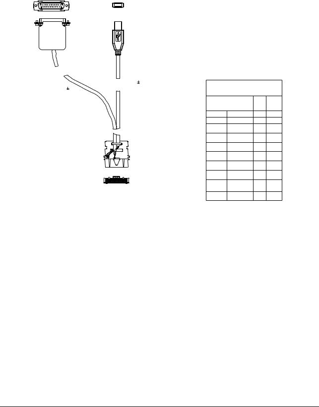
PMKN4016_ |
Mobile & Repeater Rear |
Connects the radio’s rear connector to a USB port for |
|
|
Programming, Testing & |
radio programming, data applications, testing and |
|
|
Alignment Cable |
alignment. |
|
|
|
|
|
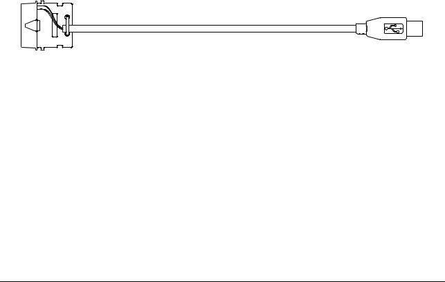
PMKN4010_ |
Mobile & Repeater Rear |
Connects the radio’s rear connector to a USB port for |
|
|
Programming Cable |
radio programming and data applications. |
|
|
|
|
2.3Programming Cables
Figure 2-1. Mobile & Repeater Rear Programming Cable PMKN4010_
February 21, 2007 |
6866576D03-A |
Test Equipment and Service Aids: Programming Cables |
2-3 |
|
|
DB 25 CONNECTOR |
USB CONNECTOR |
|
1 |
13 |
|
|
|
4 |
14 |
25 |
|
|
1455 |
24 |
|
|
|
915 15 |
CABLE |
TABLE 2: WIRE DIAGRAM |
|||
|
|
||||
CABLE |
|
|
|
|
|
|
|
|
|
26 PIN |
USB DB25P |
|
|
|
ACCESSORY PORT |
||
|
|
|
CONNECTOR |
|
|
|
|
|
PIN No. |
DESCRIPTION |
|
|
|
|
3 |
VCC (5v) |
1 |
|
|
|
2 |
DATA - |
2 |
|
TO MOBILE RADIO |
1 |
DATA + |
3 |
|
|
ACCESSORY |
||||
|
CONNECTOR |
4 |
GND |
|
|
|
|
|
|
||
|
|
|
9 |
SPEAKER - |
7 |
|
|
|
11 |
EXT MIC |
17 |
25 |
1 |
VIEWED FROM |
17 |
DIGI IN 1 |
20 |
|
|
(EXT PTT) |
|||
|
|
|
|
||
|
|
FRONT (PIN END) |
16 |
GND |
16 |
26 |
2 |
OF CONNECTOR |
|||
|
|
|
|
||
|
|
|
10 |
SPEAKER + |
1 |
Figure 2-2. Mobile & Repeater Rear Programming, Testing & Alignment Cable PMKN4016_
6866576D03-A |
February 21, 2007 |
 Loading...