


DCX3501-M
HD Dual Tuner DVR
Quick Start Guide
Before You Begin
Introduction
Congratulations on receiving a Motorola DCX3501-M HD Dual Tuner DVR. This document will help you set up your DCX3501-M set-top to quickly get it up and running.
READ THIS FIRST
1. Determine if you are connecting to a:
High-Definition TV (HDTV) Use the HDMI, component video (YPbPr), or IEEE-1394 outputs. No other video connection supports HDTV. or monitor If the TV has no HDMI input but does have a DVI input, connect a DVI-to-HDMI adapter or cable to the HDMI
out connector on the DCX set-top and the DVI input connector on the TV.
Standard-Definition TV |
Use the RF Out connector on the DCX set-top, if the TV does not support S-Video or composite video |
|
connections. The RF connection carries video and audio. |
2. Determine if you are connecting the audio to a home theater receiver or directly to the TV:
• For an HDMI or IEEE-1394 video connection, no additional audio connections to the TV are required.
•For a DVI video connection, additional audio connections to the TV are required.
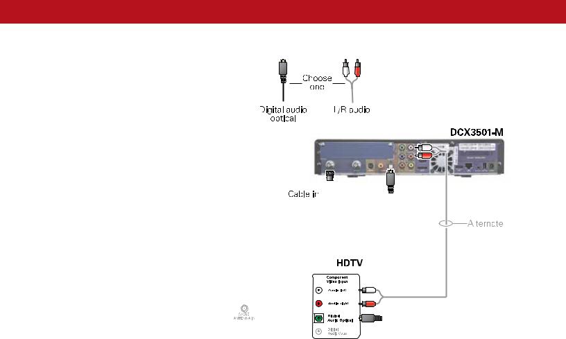
•If the receiver or TV has a digital audio (S/PDIF) input, use the Digital Audio (S/PDIF) output. Otherwise, use the left and right (RCA phono) audio outputs.
3.Locate the cabling diagram(s) that best match the configuration.
4.Connect the audio and video cables in a manner matching that diagram.
5.Connect the Cable In terminal to the coaxial cable wall outlet.
6.Connect the power cord to the set-top and the electrical wall outlet.
7.Perform the operational check for the remote control.
8.Optimize the high-definition settings.
Additional information for adjusting user settings
The DCX set-top User Settings menu allows you to adjust the video, audio, and closed captioning configuration of the set-top. The User Settings menu can be accessed from the DCX set-top remote by pressing Power and then Menu within 2 seconds.
For more detailed instructions on changing the set-top configuration through the User Settings menu, please refer to the DCX3501-M User Guide available online at http://motorola.com/homevideo/support.
DCX3501-M Quick Start Guide |
1 |

|
|
|
|
|
|
|
|
|
|
|
|
|
|
|
|
|
|
|
|
|
|
|
|
|
|
|
|
The front panel provides Power, Message, Data, and Home LAN indicators, Output |
1 |
Cursor — Menu navigation |
|||||||||||
Select — Selects menu options |
|||||||||||||
video format indicator, 4-character 7-segment display, two Recording indicators, IR |
|
||||||||||||
|
|
|
|||||||||||
remote control sensor, and buttons. |
2 |
Power — Turns the set-top on and off (standby) |
|
||||||||||
|
|
|
|
|
|
|
|
|
|
3 |
Menu — Displays the menu |
|
|
|
|
|
|
|
|
|
|
|
|
4 |
Guide — Displays the program guide |
||
|
|
|
|
|
|
|
|
|
|
||||
|
|
|
|
|
|
|
|
|
|
|
|
|
|
|
|
|
|
|
|
|
|
|
|
5 |
Info — Displays current channel and program information |
||
|
|
|
|
|
|
|
|
|
|
||||
|
|
|
|
|
|
|
|
|
|
|
|
|
|
|
|
|
|
|
|
|
|
|
|
6 |
Format* — Changes the video output format |
||
|
|
|
|
|
|
|
|
|
|
|
|
|
|
|
|
|
|
|
|
|
|
|
|
7 |
Channel — Changes channel up or down |
||
*Availability of certain features is dependent upon application support
The rear panel contains a power input; connectors for video, audio, and RF cabling; data output; and data interface connectors. Some connectors are not enabled and require the support of application software.
1Cable In — Connects to the signal from your service provider
2RF Out — Ch 3/4 modulated audio/video (SDTV) to TV or VCR
3S-Video — Connects to S-Video (SDTV) input of TV or VCR
4Digital Audio (S/PDIF)* — Provides Dolby® Digital 5.1 audio or PCM output
5YPbPr — Component video output (HDTV)
6Video — Composite video (SDTV) output
7Audio — Audio L/R outputs
8eSATA* — External Serial ATA disk interface
9HDMI — HDTV audio and video connector
10USB* 2.0 — High-Speed peripheral device connection
11Ethernet* — Network connection
12IR Remote Input — Connects to a remote control set-top accessory cable
13IEEE-1394 — Audio and HDTV video device connection (US models only)
14Power cord connector — DC input
*Feature is dependent upon application support
DCX3501-M Quick Start Guide |
2 |
Connecting Your Device
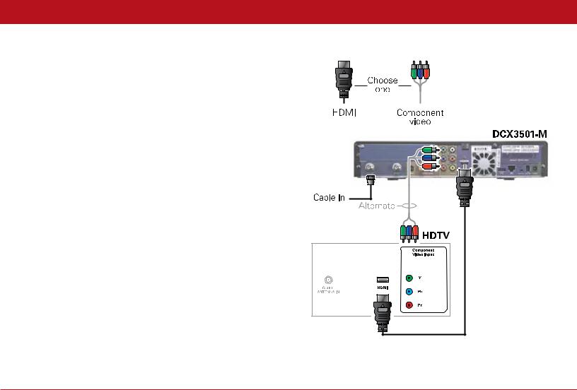
Cabling to an HDTV for Video
For the best possible HDTV video quality:
1. If the TV has an HDMI input, connect it to the DCX set-top HDMI output. If the TV has a DVI input, connect it to the DCX set-top HDMI output using an HDMI-to-DVI converter cable or adapter.
2. If the TV has neither an HDMI nor a DVI input but has an IEEE-1394 input, connect it to the DCX set-top IEEE-1394 output.
If you use IEEE-1394, on-screen graphics do not display. Otherwise, use the component video (Y, Pb, and Pr) connectors.
Note: Be sure to match up each signal to the same connection on the TV. Otherwise, the colors will not appear correctly on your TV.
L/R Audio connection or digital audio S/PDIF connection is required for sound with component video.
Note: Because HDMI provides both video and audio output, no additional audio connections to the TV are required.
DCX3501-M Quick Start Guide |
3 |
Connecting Your Device
Cabling to an HDTV for Audio
|
|
|
|
|
|
|
|
|
|
|
|
|
|
|
|
|
|
|
|
|
|
|
|
|
|
|
|
|
|
|
|
|
|
|
|
|
|
|
|
|
|
|
|
|
|
|
|
|
|
|
|
|
|
|
|
|
|
|
|
|
|
|
|
|
|
|
|
|
|
|
|
|
|
|
|
|
|
|
|
|
|
|
|
|
|
|
|
|
|
|
|
|
|
|
|
|
|
|
|
|
|
|
|
|
|
|
|
|
|
|
|
|
|
|
|
|
|
|
|
|
|
|
|
|
|
|
|
|
|
|
|
|
|
|
|
|
|
|
|
|
|
|
|
|
|
|
|
|
|
|
|
|
|
DCX3501-M Quick Start Guide |
4 |
|||||||||
 Loading...