


 Loading...
700/800-Series MVME162LX Embedded Controller Installation and Use
V162-7A/IH1
Notice
While reasonable efforts have been made to assure the accuracy of this document, Motorola, Inc. assumes no liability resulting from any omissions in this document, or from the use of the information obtained therein. Motorola reserves the right to revise this document and to make changes from time to time in the content hereof without obligation of Motorola to notify any person of such revision or changes.
No part of this material may be reproduced or copied in any tangible medium, or stored in a retrieval system, or transmitted in any form, or by any means, radio, electronic, mechanical, photocopying, recording or facsimile, or otherwise, without the prior written permission of Motorola, Inc.
It is possible that this publication may contain reference to, or information about Motorola products (machines and programs), programming, or services that are not announced in your country. Such references or information must not be construed to mean that Motorola intends to announce such Motorola products, programming, or services in your country.
Restricted Rights Legend
If the documentation contained herein is supplied, directly or indirectly, to the U.S. Government, the following notice shall apply unless otherwise agreed to in writing by Motorola, Inc.
Use, duplication, or disclosure by the Government is subject to restrictions as set forth in subparagraph (c)(1)(ii) of the Rights in Technical Data and Computer Software clause at DFARS 252.227-7013.
Motorola, Inc.
Computer Group
2900 South Diablo Way
Tempe, Arizona 85282-9602
Preface
This document provides general information and basic installation instructions for the 700/800-series MVME162LX VME Embedded Controller, which is available in the versions listed below.
Assembly Item |
Board Description |
|
|
MVME162-723 |
32MHz, 4MB DRAM |
|
|
MVME162-743 |
32MHz, 4MB ECC |
|
DRAM |
|
|
MVME162-763 |
32MHz, 16MB ECC |
|
DRAM |
|
|
Assembly |
Board |
Item |
Description |
|
|
MVME162-813 |
32MHz, 8MB |
|
DRAM |
|
|
MVME162-833 |
32MHz, 8MB |
|
ECC DRAM |
|
|
MVME162-853 |
32MHz, 32MB |
|
ECC DRAM |
|
|
MVME162-863 |
32MHz, 16MB |
|
ECC DRAM |
|
|
In 700/800-Series MVME162LX Embedded Controller Installation and Use you will find a general board-level hardware description, hardware preparation and installation instructions, a description of the debugger firmware, and information on using the firmware on the MVME162LX VME Embedded Controller.
This manual is intended for anyone who wants to design OEM systems, supply additional capability to an existing compatible system, or work in a lab environment for experimental purposes. A basic knowledge of computers and digital logic is assumed.
Companion publications are listed beginning on page 1-3.

Safety Summary
Safety Depends On You
The following general safety precautions must be observed during all phases of operation, service, and repair of this equipment. Failure to comply with these precautions or with specific warnings elsewhere in this manual violates safety standards of design, manufacture, and intended use of the equipment. Motorola, Inc. assumes no liability for the customer's failure to comply with these requirements.
The safety precautions listed below represent warnings of certain dangers of which Motorola is aware. You, as the user of the product, should follow these warnings and all other safety precautions necessary for the safe operation of the equipment in your operating environment.
Ground the Instrument.
To minimize shock hazard, the equipment chassis and enclosure must be connected to an electrical ground. The equipment is supplied with a three-conductor AC power cable. The power cable must be plugged into an approved three-contact electrical outlet. The power jack and mating plug of the power cable must meet International Electrotechnical Commission (IEC) safety standards.
Do Not Operate in an Explosive Atmosphere.
Do not operate the equipment in the presence of flammable gases or fumes. Operation of any electrical equipment in such an environment constitutes a definite safety hazard.
Keep Away From Live Circuits.
Operating personnel must not remove equipment covers. Only Factory Authorized Service Personnel or other qualified maintenance personnel may remove equipment covers for internal subassembly or component replacement or any internal adjustment. Do not replace components with the power cable connected. Under certain conditions, dangerous voltages may exist even with the power cable removed. To avoid injuries, always disconnect power and discharge circuits before touching them.
Do Not Service or Adjust Alone.
Do not attempt internal service or adjustment unless another person capable of rendering first aid and resuscitation is present.
Use Caution When Exposing or Handling the CRT.
Breakage of the Cathode-Ray Tube (CRT) causes a high-velocity scattering of glass fragments (implosion). To prevent CRT implosion, avoid rough handling or jarring of the equipment. Handling of the CRT should be done only by qualified maintenance personnel using approved safety mask and gloves.
Do Not Substitute Parts or Modify Equipment.
Because of the danger of introducing additional hazards, do not install substitute parts or perform any unauthorized modification of the equipment. Contact your local Motorola representative for service and repair to ensure that safety features are maintained.
Dangerous Procedure Warnings.
Warnings, such as the example below, precede potentially dangerous procedures throughout this manual. Instructions contained in the warnings must be followed. You should also employ all other safety precautions which you deem necessary for the operation of the equipment in your operating environment.
Dangerous voltages, capable of causing death, are
! present in this equipment. Use extreme caution when WARNING handling, testing, and adjusting.

Lithium Battery Caution
The board contains a lithium battery to power the clock and calendar circuitry.
Danger of explosion if battery is replaced incorrectly. ! Replace only with the same or equivalent type
CAUTION recommended by the equipment manufacturer. Dispose of used batteries according to the manufacturer’s instructions.
Il y a danger d’explosion s’il y a remplacement incorrect ! de la batterie. Remplacer uniquement avec une batterie
Attention du même type ou d’un type équivalent recommandé par le constructeur. Mettre au rebut les batteries usagées conformément aux instructions du fabricant.
Explosionsgefahr bei unsachgemäßem Austausch der ! Batterie. Ersatz nur durch denselben oder einen vom Vorsicht Hersteller empfohlenen Typ. Entsorgung gebrauchter
Batterien nach Angaben des Herstellers.

All Motorola PWBs (printed wiring boards) are manufactured by UL-recognized manufacturers, with a flammability rating of 94V-0.
This equipment generates, uses, and can radiate electro- ! magnetic energy. It may cause or be susceptible to
WARNING electro-magnetic interference (EMI) if not installed and used in a cabinet with adequate EMI protection.
European Notice: Board products with the CE marking comply with the EMC Directive (89/336/EEC). Compliance with this directive implies conformity to the following European Norms:
EN55022 (CISPR 22) Radio Frequency Interference
EN50082-1 (IEC801-2, IEC801-3, IEC801-4) Electromagnetic Immunity
The product also fulfills EN60950 (product safety), which is essentially the requirement for the Low Voltage Directive (73/23/EEC).
This board product was tested in a representative system to show compliance with the above mentioned requirements. A proper installation in a CE-marked system will maintain the required EMC/safety performance.
The computer programs stored in the Read Only Memory of this device contain material copyrighted by Motorola Inc., 1995, and may be used only under a license such as those contained in Motorola’s software licenses.
Motorola® and the Motorola symbol are registered trademarks of Motorola, Inc.
All other products mentioned in this document are trademarks or registered trademarks of their respective holders.
©Copyright Motorola 1997
All Rights Reserved
Printed in the United States of America
October 1997

Contents
Lithium Battery Caution 5 Introduction 1-1
Overview 1-1
Related Documentation 1-3 Documents for the MVME162LX 1-4
Other Applicable Motorola Publications 1-4
Applicable Non-Motorola Publications 1-5 Requirements 1-6
Features 1-6 Specifications 1-9
Cooling Requirements 1-10
Special Considerations for Elevated-Temperature Operation 1-10 FCC Compliance 1-12
Manual Terminology 1-12 Block Diagram 1-14 Functional Description 1-14
Front Panel Switches and Indicators 1-14 Data Bus Structure 1-16
Microprocessor 1-16 MC68040 Cache 1-16
No-VMEbus-Interface Option 1-17 Memory Options 1-17
DRAM Options 1-17
SRAM Options 1-18 About the Battery 1-19
EPROM and Flash Memory 1-21
Battery Backed Up RAM and Clock 1-21
VMEbus Interface and VMEchip2 1-21 I/O Interfaces 1-22
Serial Communications Interface 1-22 IndustryPack (IP) Interfaces 1-23 Optional Ethernet Interface 1-23 Optional SCSI Interface 1-24
SCSI Termination 1-24 Local Resources 1-25
Programmable Tick Timers 1-25 Watchdog Timer 1-25

Software-Programmable Hardware Interrupts 1-26
Local Bus Timeout 1-26
Local Bus Arbiter 1-27
Connectors 1-27
Memory Maps 1-28
Local Bus Memory Map 1-28
Normal Address Range 1-28
VMEbus Memory Map 1-34
VMEbus Accesses to the Local Bus 1-34
VMEbus Short I/O Memory Map 1-34
Introduction 2-1
Unpacking Instructions 2-1
Hardware Preparation 2-1
System Controller Select Header (J1) 2-3
IP Bus Clock Header (J11) 2-5
SCSI Terminator Enable Header (J12) 2-6
SRAM Backup Power Source Select Header (J14) 2-6
Flash Write Protect Header (J16) 2-7
IP Bus Strobe Select Header (J18) 2-8
IP DMA Snoop Control Header (J19) 2-8
EPROM/Flash Configuration Header (J20) 2-9
General-Purpose Readable Jumpers Header (J21) 2-12
Memory Mezzanine Options 2-13
Installation Instructions 2-14
IP Installation on the MVME162LX 2-15
MVME162LX Installation 2-16
System Considerations 2-18
Overview of M68000 Firmware 3-1
Description of 162Bug 3-1
162Bug Implementation 3-3
Installation and Startup 3-3
Prom Versions 3-7
Autoboot 3-7
ROMboot 3-9
Network Boot 3-10
Restarting the System 3-10
Reset 3-11
Abort 3-11
Break 3-12
SYSFAIL* Assertion/Negation 3-12
MPU Clock Speed Calculation 3-13

Memory Requirements 3-13 Disk I/O Support 3-15
Blocks Versus Sectors 3-15
Device Probe Function 3-16
Disk I/O via 162Bug Commands 3-16 IOI (Input/Output Inquiry) 3-16 IOP (Physical I/O to Disk) 3-16 IOT (I/O Teach) 3-17
IOC (I/O Control) 3-17
BO (Bootstrap Operating System) 3-17 BH (Bootstrap and Halt) 3-17
Disk I/O via 162Bug System Calls 3-17
Default 162Bug Controller and Device Parameters 3-19 Disk I/O Error Codes 3-19
Network I/O Support 3-19
Intel 82596 LAN Coprocessor Ethernet Driver 3-20 UDP/IP Protocol Modules 3-20
RARP/ARP Protocol Modules 3-21 BOOTP Protocol Module 3-21 TFTP Protocol Module 3-21 Network Boot Control Module 3-21 Network I/O Error Codes 3-22
Multiprocessor Support 3-22
Multiprocessor Control Register (MPCR) Method 3-22 GCSR Method 3-24
Diagnostic Facilities 3-25 Manufacturing Test Process 3-25 In This Chapter 4-1
Entering Debugger Command Lines 4-1 Terminal Input/Output Control 4-1 Debugger Command Syntax 4-3 Syntactic Variables 4-3
Expression as a Parameter 4-3 Address as a Parameter 4-5 Address Formats 4-6
Offset Registers 4-7 Port Numbers 4-9
Entering and Debugging Programs 4-9
Creating a Program with the Assembler/Disassembler 4-10 Downloading an S-Record Object File 4-10
Read the Program from Disk 4-10

Calling System Utilities from User Programs 4-11 Preserving the Debugger Operating Environment 4-11
162Bug Vector Table and Workspace 4-12 Examples 4-12
Hardware Functions 4-13
Exception Vectors Used by 162Bug 4-13 Exception Vector Tables 4-15
Using 162Bug Target Vector Table 4-15 Creating a New Vector Table 4-16
Floating Point Support 4-18 Single Precision Real 4-19 Double Precision Real 4-19 Scientific Notation 4-20
The 162Bug Debugger Command Set 4-20
Configure Board Information Block A-1
Set Environment to Bug/Operating System A-3 Configuring the IndustryPacks A-14
Disk/Tape Controller Modules Supported B-1 Disk/Tape Controller Default Configurations B-2
IOT Command Parameters for Supported Floppy Types B-4 Network Controller Modules Supported C-1
Solving Startup Problems D-1
1Board Level Hardware
Description 1
Introduction
This chapter describes the board level hardware features of the 700/800-series MVME162LX VME Embedded Controller. The chapter is organized with a board level overview and features list in this introduction, followed by a more detailed hardware functional description. Front panel switches and indicators are included in the detailed hardware functional description. The chapter closes with some general memory maps.
All MVME162LX programmable registers that reside in ASICs are covered in the MVME162LX Embedded Controller Programmer’s Reference Guide.
Overview
The MVME162LX is based on the MC68040 microprocessor. Various versions of the MVME162LX have parity-protected DRAM (4MB, 8M, or 16MB); or ECC-protected DRAM (4MB, 8MB, 16MB, or 32MB); 128KB of SRAM (with battery backup); a time-of-day clock (with battery backup); an optional LAN Ethernet transceiver interface; four serial ports with EIA-232-D interface; six tick timers with watchdog timer(s); two EPROM sockets; 2MB Flash memory (one Flash device); two IndustryPack (IP) interfaces with DMA; optional SCSI bus interface with DMA; and an optional VMEbus interface (local bus to VMEbus/VMEbus to local bus, with A16/A24/A32, D8/D16/D32 bus widths and a VMEbus system controller).
Input/Output (I/O) signals are routed through industry-standard connectors on the MVME162LX front panel; no adapter boards or transition modules are required. I/O connections include an optional 68-pin SCSI connector, an optional DB-15 Ethernet
1-1

1 |
Board Level Hardware Description
connector, and four 8-pin RJ-45 serial connectors on the front panel. In addition, the panel has cutouts for routing of flat cables to the optional IndustryPack modules.
The following ASICs are used on the MVME162LX:
VMEchip2. (VMEbus interface). Provides two tick timers, a watchdog timer, programmable map decoders for the master and slave interfaces, and a VMEbus to/from local bus DMA controller, a VMEbus to/from local bus non-DMA programmed access interface, a VMEbus interrupter, a VMEbus system controller, a VMEbus interrupt handler, and a VMEbus requester.
Processor-to-VMEbus transfers are D8, D16, or D32. VMEchip2 DMA transfers to the VMEbus, however, are D16, D32, D16/BLT, D32/BLT, or D64/MBLT.
MC2chip. Provides four tick timers, the interface to the LAN chip, SCSI chip, serial port chip, BBRAM, EPROM/Flash, parity DRAM and SRAM.
MCECC memory controller. Provides the programmable interface for the ECC-protected DRAM mezzanine board.
IndustryPack Interface Controller (IP2). The IP2 provides control and status information for up to two single-wide IndustryPacks (IPs) or one double-wide IP that can be plugged into the MVME162LX main board.
1-2

Introduction |
1 |
|
Related Documentation
The MVME162LX ships with an installation and use manual (the document you are presently reading, Motorola publications number VME162-7A/IH) which includes installation instructions, jumper configuration information, memory maps, debugger/ monitor commands, and any other information needed to start up the board.
If you plan to develop your own applications or need more detailed information about your MVME162LX VME Embedded Controller, you may wish to order the additional documentation listed on the following pages. You can contact Motorola for this purpose in several ways:
Through your local Motorola sales office
Through the World Wide Web site listed on the back cover of this and other MCG manuals
(USA and Canada only) — By contacting the Literature Center via phone or fax at the numbers listed under Product Literature at MCG’s World Wide Web site
If any supplements have been issued for a manual or guide, they will be furnished along with that document. Each Motorola Computer Group manual publication number is suffixed with characters which represent the revision level of the document, such as “/IH2” (the second revision of a manual); a supplement bears the same number as a manual but has a suffix such as “/IH2A1” (the first supplement to the second edition of the manual).
1-3
1 |
Board Level Hardware Description |
|
Documents for the MVME162LX
The following MCG publications are applicable to the 700/800series MVME162LX and may provide additional helpful information. If they are not shipped with this product, you can obtain them by contacting your local Motorola sales office.
Motorola |
Description |
|
Publication Number |
||
|
||
|
|
|
MVME162LXPG/D |
MVME162LX Embedded Controller Programmer’s Reference |
|
|
Guide |
|
|
|
|
MVME162BUG/D |
MVME162Bug Debugging Package User's Manual |
|
|
|
|
68KBUG1/D |
Debugging Package for Motorola 68K CISC CPUs User’s |
|
68KBUG2/D |
Manual (Parts 1 and 2) |
|
|
|
|
SBCSCSI/D |
Single Board Computers SCSI Software User’s Manual |
|
|
|
Other Applicable Motorola Publications
The following publications are also applicable to the 700/800-series
MVME162LX and may provide additional helpful information.
They may be purchased through your local Motorola sales office.
Motorola
Description
Publication Number
M68000FR |
M68000 Family Reference Manual |
|
|
M68040UM |
MC68040 Microprocessors User's Manual |
1-4

Introduction |
1 |
|
Applicable Non-Motorola Publications
The following non-Motorola publications are also available from the sources indicated.
Document Title |
Source |
|
|
VME64 Specification, order number |
VITA (VMEbus International |
ANSI/VITA 1-1994 |
Trade Association) |
|
7825 E. Gelding Dr., Ste. 104 |
Note: An earlier version of the VME |
Scottsdale, AZ 85260-3415 |
specification is available as Versatile Backplane |
|
Bus: VMEbus, ANSI/IEEE Std 1014-1987 |
|
(VMEbus Specification). This is also available as |
|
Microprocessor System Bus for 1 to 4 Byte Data |
|
(IEC 821 BUS). |
|
|
|
ANSI Small Computer System Interface-2 |
Global Engineering Documents |
(SCSI-2), Draft Document X3.131-198X, |
15 Inverness Way East |
Revision 10c |
Englewood, CO 80112-5704 |
|
|
82596CA Local Area Network Coprocessor |
Intel Corporation |
Data Sheet, order number 290218; and |
Literature Sales |
82596 User's Manual, order number 296853 |
P.O. Box 58130 |
|
Santa Clara, CA 95052-8130 |
|
|
28F016SA Flash Memory Data Sheet, |
Intel Corporation |
order number 290435 |
Literature Sales |
|
P.O. Box 7641, Mt. Prospect, IL |
|
60056-7641 |
|
|
1-5

1 |
Board Level Hardware Description
Document Title |
Source |
|
|
|
|
NCR 53C710 SCSI I/O Processor Data Manual, |
NCR Corporation |
|
order number NCR53C710DM |
Microelectronics Products Division |
|
|
1635 Aeroplaza Dr. |
|
NCR 53C710 SCSI I/O Processor Programmer’s |
||
Colorado Springs, CO 80916 |
||
Guide, order number NCR53C710PG |
||
|
||
|
|
|
SGS-THOMSON 64K (8K x 8) Timekeeper® |
SGS-THOMSON Microelectronics |
|
SRAM Data Sheet, order number M48T08/18 |
Group |
|
|
Marketing Headquarters |
|
|
1000 East Bell Rd. |
|
|
Phoenix, AZ 85022-2699 |
|
|
|
|
IndustryPack Logic Interface Specification, |
VITA (VMEbus International |
|
Revision 1.0, order number ANSI/VITA 4-1995 |
Trade Association) |
|
|
7825 E. Gelding Dr., Ste. 104 |
|
|
Scottsdale, AZ 85260-3415 |
|
|
|
|
Z85230 Serial Communications Controller Data |
Zilog Inc. |
|
Sheet |
210 Hacienda Ave. |
|
|
Campbell, CA 95008-6609 |
|
|
|
Requirements
These boards are designed to conform to the requirements of the following documents:
VME64 Specification, VITA
EIA-232-D Serial Interface Specification, EIA
SCSI Specification, ANSI
IndustryPack Specification, VITA
Features
The following table summarizes the features of the 700/800-series MVME162LX VMEmodule.
1-6

|
Introduction |
Table 1-1. 700/800-Series MVME162LX: Features |
|
|
|
Feature |
Description |
|
|
Microprocessor |
32MHz MC68040 |
|
|
DRAM mezzanine |
4/8/16MB with parity protection, or 4/8/16/32MB with |
|
ECC protection |
|
|
SRAM |
128KB static RAM (SRAM) with battery backup |
|
|
EPROM |
Two JEDEC standard 32-pin DIP PROM sockets |
|
|
Flash memory |
One Intel 28F016SA 2M x 8 Flash memory device with |
|
write protection (optional) |
|
|
NVRAM |
8K by 8 Non-Volatile RAM (NVRAM) and time-of-day |
|
(TOD) clock with battery backup |
|
|
Switches |
RESET and ABORT switches |
|
|
Status LEDs |
Status LEDs for FAIL, RUN, SCON, and FUSES |
|
|
Tick Timers |
Four 32-bit tick timers (in the MC2chip ASIC); two 32-bit |
|
tick timers (in the VMEchip2 ASIC) for periodic interrupts |
|
|
Watchdog timers |
Two 32-bit watchdog timers (one each in the MC2chip and |
|
VMEchip2 ASICs) |
|
|
Interrupts |
Eight software interrupts (for MVME162LX versions that |
|
have the VMEchip2) |
|
|
Serial I/O |
Four serial ports with EIA-232-D interface (serial port |
|
controllers are the Z85230 chips) |
|
|
SCSI I/O |
Optional SCSI Bus interface with DMA |
|
|
Ethernet I/O |
Optional Ethernet transceiver interface with DMA |
|
|
IndustryPack I/O |
Two IP interfaces with two-channel DMA |
|
|
1 |
1-7

1 |
Board Level Hardware Description
Table 1-1. 700/800-Series MVME162LX: Features (Continued)
Feature |
Description |
|
|
|
VMEbus system controller functions |
|
|
|
VMEbus interface to local bus (A24/A32, |
|
D8/D16/D32/block transfer [D8/D16/D32/D64]) |
|
|
|
Local-bus-to-VMEbus interface (A16/A24/A32, |
|
D8/D16/D32) |
|
|
VMEbus interface |
VMEbus interrupter |
|
|
|
VMEbus interrupt handler |
|
|
|
Global control/status register for interprocessor |
|
communications |
|
|
|
DMA for fast local memory - VMEbus transfers |
|
(A16/A24/A32, D16/D32/block transfer) |
|
|
1-8
Introduction |
1 |
|
Specifications
Table 1-2 lists the specifications for a 700/800-series MVME162LX without IPs.
Table 1-2. 700/800-Series MVME162LX: Specifications
Characteristics |
Specifications |
|
|
|
|
Power requirements |
+5Vdc (± 5%), 3.5 A typical, 4.5 A maximum |
|
(with EPROMs; without IPs) |
+12 Vdc (± 5%), 100 mA maximum |
|
|
-12 Vdc (± 5%), 100 mA maximum |
|
|
|
|
Operating temperature |
0˚ to 70˚ C exit air with forced air cooling* |
|
|
(see Note) |
|
|
|
|
Storage temperature |
-40˚ to +85˚ C |
|
|
|
|
Relative humidity |
5% to 90% (noncondensing) |
|
|
|
|
Physical dimensions |
Double-high VMEboard |
|
PC board with mezzanine |
|
|
module only |
9.2 inches (233 mm) |
|
Height |
||
Depth |
6.3 inches (160 mm) |
|
Thickness |
0.66 inch (17 mm) |
|
PC board with connectors |
|
|
and front panel |
10.3 inches (262 mm) |
|
Height |
||
7.4 inches (188 mm) |
||
Depth |
||
0.80 inch (20 mm) |
||
Thickness |
||
|
||
|
|
*Refer to Cooling Requirements on page 1-10 and Special Considerations for ElevatedTemperature Operation on page 1-10.
1-9

1 |
Board Level Hardware Description |
|
Cooling Requirements
The Motorola MVME162LX VME Embedded Controller is specified, designed, and tested to operate reliably with an incoming air temperature range from 0˚ to 55˚ C (32˚ to 131˚ F) with forced air cooling at a velocity typically achievable by using a 100 CFM axial fan. Temperature qualification is performed in a standard Motorola VME system chassis. Load boards are inserted adjacent to the board under test, to simulate a high power density system configuration. An assembly of three axial fans, rated at 100 CFM per fan, is placed directly under the VME card cage. The incoming air temperature is measured between the fan assembly and the card cage, where the incoming airstream first encounters the controller under test. Test software is executed as the controller is subjected to ambient temperature variations. Case temperatures of critical, high power density integrated circuits are monitored to ensure that component vendors’ specifications are not exceeded.
While the exact amount of airflow required for cooling depends on the ambient air temperature and the type, number, and location of boards and other heat sources, adequate cooling can usually be achieved with 10 CFM and 490 LFM flowing over the controller. Less airflow is required to cool the controller in environments having lower maximum ambients. Under more favorable thermal conditions (refer to Elevated-Temperature Operation below), it may be possible to operate the controller reliably at higher than 55˚ C with increased airflow. It is important to note that there are several factors, in addition to the rated CFM of the air mover, which determine the actual volume and speed of air flowing over the controller.
Special Considerations for Elevated-Temperature Operation
The following information is for users whose applications for the
MVME162LX may subject it to high temperatures.
1-10
Introduction |
1 |
|
The MVME162LX uses commercial-grade devices. Therefore, it can operate in an environment with ambient air temperatures from 0˚ C to 70˚ C. Several factors influence the ambient temperature seen by components on the MVME162LX. Among them are inlet air temperature; airflow characteristics; number, types, and locations of IP modules; power dissipation of adjacent boards in the system, etc.
A temperature profile of a comparable board (the MVME172 embedded controller) was developed in an MVME954A six-slot VME chassis. Two such boards, each loaded with one 4MB memory mezzanine and two GreenSpring IndustryPack modules, were placed in the chassis with one 36W load board installed between them. The chassis was placed in a thermal chamber that maintained an ambient temperature of 55˚ C. Measurements showed that the fans in the chassis supplied an airflow of approximately 65 LFM over the MVME172 boards. Under these conditions, a rise in temperature of approximately 10˚ C between the inlet and exit air was observed. The junction temperatures of selected high-power devices on the MVME172 were calculated (from case temperature measurements) and were found to be within manufacturers’ specified tolerances.
! |
For elevated-temperature operation, perform similar |
measurements and calculations to determine the actual |
|
Caution |
operating margin for your specific environment. |
To facilitate elevated-temperature operation:
1.Position the MVME162LX in the chassis to permit maximum airflow over the component side of the board.
2.Do not place boards with high power dissipation next to the MVME162LX.
3.Use low-power IP modules only.
1-11

1 |
Board Level Hardware Description |
|
FCC Compliance
The MVME162LX is a board-level product and is meant to be used in standard VME applications. As such, it is the responsibility of system integrators to to meet the regulatory guidelines pertaining to a given application. The MVME162LX has been tested in a representative chassis for CE class B EMC certification. Compliance was achieved under the following conditions:
1.Shielded cables on all external I/O ports.
2.Cable shields connected to earth ground via metal shell connectors bonded to a conductive module front panel.
3.Conductive chassis rails connected to earth ground. This provides the path for connecting shields to earth ground.
4.Front panel screws properly tightened.
For minimum RF emissions, it is essential that the conditions above be implemented. Failure to do so could compromise the FCC compliance of the equipment containing the module.
Manual Terminology
Throughout this manual, a convention is used which precedes data and address parameters by a character identifying the numeric format as follows:
$ |
dollar |
specifies a hexadecimal character |
% |
percent |
specifies a binary number |
& |
ampersand |
specifies a decimal number |
For example, “12” is the decimal number twelve, and ‘‘$12’’ is the decimal number eighteen.
Unless otherwise specified, all address references are in hexadecimal.
1-12

Introduction
1
An asterisk (*) following the signal name for signals which are level significant denotes that the signal is true or valid when the signal is low.
An asterisk (*) following the signal name for signals which are edge significant denotes that the actions initiated by that signal occur on high-to-low transition.
In this manual, assertion and negation are used to specify forcing a signal to a particular state. In particular, assertion and assert refer to a signal that is active or true; negation and negate indicate a signal that is inactive or false. These terms are used independently of the voltage level (high or low) that they represent.
Data and address sizes are defined as follows:
A byte is eight bits, numbered 0 through 7, with bit 0 being the least significant.
A two-byte is 16 bits, numbered 0 through 15, with bit 0 being the least significant. For the MVME162LX and other CISC modules, this is called a word.
A four-byte is 32 bits, numbered 0 through 31, with bit 0 being the least significant. For the MVME162LX and other CISC modules, this is called a longword.
The terms control bit, status bit, true and false are used extensively in this document.
The term control bit describes a bit in a register that can be set and cleared under software control. The term true indicates that a bit is in the state that enables the function it controls. The term false indicates that the bit is in the state which disables the function it controls. In all tables, the terms 0 and 1 describe the actual value that should be written to the bit, or the value that it yields when read.
The term status bit describes a bit in a register that reflects a specific condition. The status bit is read by software to determine operational or exception conditions.
1-13

1 |
Board Level Hardware Description |
|
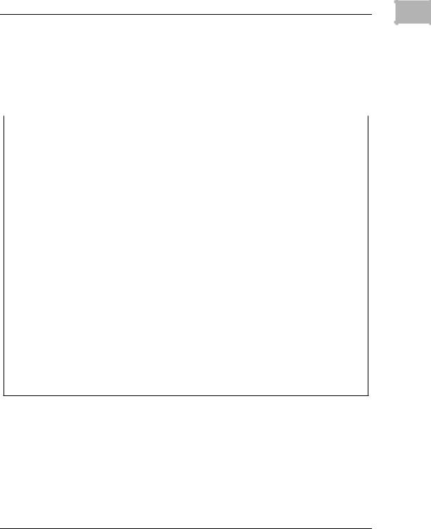
Block Diagram
Refer to Figure 1-1 on page 1-15 for a block diagram of the 700/800series MVME162LX.
Functional Description
This section contains a functional description of the major blocks on the MVME162LX.
Front Panel Switches and Indicators
There are two switches and four LEDs on the front panel of the
MVME162LX.
RESET switch. Resets all onboard devices (including IP modules, if installed) and drives SYSRESET* if the board is system controller. The RESET switch may be disabled by software.
ABORT switch. When enabled by software, the ABORT switch generates an interrupt at a user-programmable level. It is normally used to abort program execution and return to the 162Bug debugger.
FAIL LED (red). Lights when the BRDFAIL* signal line is active or when the processor is halted. Part of DS1.
RUN LED (green or amber). Lights when the local bus TIP* signal line is low. This indicates one of the local bus masters is executing a local bus cycle. Part of DS1.
SCON LED (green). Lights when the VMEchip2 in the MVME162LX is the VMEbus system controller. Part of DS2.
FUSES LED (green). Lights when +5Vdc, +12Vdc, and -12Vdc power is available to the LAN and SCSI interfaces and IP connectors. Part of DS2.
1-14

Diagram Block MVME162LX .1-1 Figure
15-1
Optional |
|
|
Optional |
|
4 Serial Ports |
|
|
|
|
|
RJ-45 Front |
|
|
Ethernet |
SCSI |
|
Panel |
VMEbus |
IndustryPack |
Transceiver |
Peripherals |
|
|
DB-15 Front |
68-pin Front |
|
|
||
A32/24:D64/32/16/08 |
I/O |
Panel |
Panel SCSI |
|
|
Master/Slave |
2 Channels |
Connector |
Connector |
|
EIA-232 |
|
|
|
|
|
|
|
|
|
|
|
Transceivers |
VMEchip2 |
IP2 |
i82596CA |
53C710 |
Two 32-pin |
Dual 85230 |
VMEbus |
IndustryPack |
Ethernet |
SCSI |
EPROM |
Serial |
Interface |
Interface |
Controller |
Coprocessor |
Sockets |
I/O Controllers |
|
|
|
|
|
Optional |
|
A32/D32 |
|
|
MC2chip |
Flash |
|
|
|
|
2MB |
|
|
|
|
|
|
|
|
|
|
|
|
|
|
|
|
|
|
|
|
|
|
|
|
|
|
|
|
|
|
|
|
|
|
|
|
|
|
|
|
|
|
|
|
|
|
|
|
|
|
|
|
|
|
|
|
|
|
|
|
|
|
|
|
M48T58 |
|
|
|
|
|
|
|
|
|
|
|
|
|
|
|
|
|
|
|
|
|
|
|
MC68040 |
|
|
|
|
|
|
|
|
|
|
|
|
|
Battery Backed |
|
||
|
|
MPU |
|
|
|
|
|
|
|
|
|
|
|
|
|
|
8KB RAM/Clock |
|
|
|
|
Optional |
|
|
|
|
4,8,16MB Parity |
|
|
|
4,8,16,32MB |
|
|
|
|
|
|
|
|
|
|
|
|
|
DRAM Memory |
|
|
|
ECC DRAM |
|
|
|
|
|
|
|
|
||
|
|
MC68040 |
|
|
|
|
|
|
|
|
|
|
|
128KB SRAM |
|
||||
|
|
|
|
|
Array |
|
|
Memory Array |
|
|
|
|
|
|
|
||||
|
|
|
|
|
|
|
|
|
|
|
|
|
|
|
|
|
|
Memory Array |
|
|
|
|
|
|
|
|
Configuration Dependent |
|
|
|
|
|
w/Battery |
|
|||||
|
|
|
|
|
|
|
|
|
|
|
|
|
|
|
|
|
|
|
|
21009702
Description Functional
1 |

1 |
Board Level Hardware Description |
|
Data Bus Structure
The local bus on the MVME162LX is a 32-bit synchronous bus that is based on the MC68040 bus, and which supports burst transfers and snooping. The various local bus master and slave devices use the local bus to communicate. The local bus is arbitrated by priority type arbiter and the priority of the local bus masters from highest to lowest is: 82596CA LAN, 53C710 SCSI, VMEbus, and MPU. In the general case, any master can access any slave; however, not all combinations pass the common sense test. Refer to the
MVME162LX Embedded Controller Programmer’s Reference Guide and to the user's guide for each device to determine its port size, data bus connection, and any restrictions that apply when accessing the device.
Microprocessor
The MVME162LX is built with a 32MHz MC68040 microprocessor.
The MC68040 has on-chip instruction and data caches, optional high drive I/O buffers, and a floating point processor. The MC68040 supports cache coherency in multi-master applications with dedicated on-chip bus snooping logic. Refer to the M68040 reference manual for detailed information.
MC68040 Cache
The MVME162LX local bus masters (VMEchip2, MC68040, 53C710 SCSI controller, and 82596CA Ethernet controller) have programmable control of the snoop/caching mode. The IP DMA local bus master’s snoop control function is controlled by jumper settings at J19. J19 controls the state of the snoop control signals for all IP DMA transfers (including the IP DMA which is executed when the DMA control registers are updated during IP DMA operation in the command chaining mode). The MVME162LX local bus slaves that support MC68040 bus snooping are defined in the Local Bus Memory Map table later in this chapter.
1-16

Functional Description |
1 |
|
No-VMEbus-Interface Option
The 700/800-series MVME162LX may be operated as an embedded controller without the VMEbus interface. For this option, the VMEchip2 ASIC and the VMEbus buffers are not populated. Also, the bus grant daisy chain and the interrupt acknowledge daisy chain have zero-ohm bypass resistors installed.
To support this feature, certain logic in the VMEchip2 has been duplicated in the MC2chip. This logic is inhibited in the MC2chip when the VMEchip2 is present. The enables for these functions are controlled by software and MC2chip hardware initialization.
Note that MVME162LX models ordered without the VMEbus interface are shipped with Flash memory blank (the factory uses the VMEbus to program the Flash memory with debugger code). To use the 162Bug package, MVME162Bug, be sure that jumper header J21 is configured for the EPROM memory map. Refer to Chapters 2 and 3 for further details.
Contact your local Motorola sales office for ordering information.
Memory Options
The following memory options are used on the different versions of 700/800-series MVME162LX boards.
DRAM Options
The MVME162LX offers the following DRAM options:
4, 8, or 16MB shared DRAM with programmable parity on a mezzanine module
4, 8, 16, or 32MB ECC DRAM on a mezzanine module
The DRAM architecture for non-ECC memory is non-interleaved for 4 or 8MB and interleaved for 16MB. Parity protection is enabled with interrupts or bus exception when a parity error is detected.
1-17

1 |
Board Level Hardware Description
DRAM performance is specified in the section on the DRAM Memory Controller in the MC2chip Programming Model in the
MVME162LX Embedded Controller Programmer’s Reference Guide.
The DRAM map decoder may be programmed to accommodate different base address(es) and sizes of mezzanine boards. The onboard DRAM is disabled by a local bus reset and must be programmed before the DRAM may be accessed. Refer to the MC2chip and MCECC descriptions in the MVME162LX Embedded Controller Programmer’s Reference Guide for detailed programming information.
Most DRAM devices require some number of access cycles before the DRAMs are fully operational. Normally this requirement is met by the onboard refresh circuitry and normal DRAM initialization. However, software should insure a minimum of 10 initialization cycles are performed to each bank of RAM.
SRAM Options
The MVME162LX provides 128KB of 32-bit-wide onboard static RAM in a single non-interleaved architecture with onboard battery backup. The SRAM arrays are not parity protected.
The SRAM battery backup function is provided by a Dallas DS1210S device. The DS1210S supports primary and secondary power sources. When the main board power fails, the DS1210S selects the source with the higher voltage. If one source should fail, the DS1210S switches to the redundant source. Each time the board is powered up, the DS1210S checks power sources and if the voltage of the backup source is less than two volts, the second memory cycle is blocked. This allows software to provide an early warning to avoid data loss. Because the DS1210S may block the second access, software should do at least two accesses before relying on the data.
The MVME162LX provides jumpers (on J14) that allow either power source of the DS1210S to be connected to the VMEbus +5V STDBY pin or to one cell of the onboard battery. For example, the primary system backup source may be a battery connected to the
1-18

Functional Description |
1 |
|
VMEbus +5V STDBY pin and the secondary source may be the onboard battery. If the system source should fail or the board is removed from the chassis, the onboard battery takes over. Refer to Chapter 2 for the jumper configurations.
For proper operation of the SRAM, some jumper
! combination must be installed on the respective Backup Caution Power Source Select Header (J14). If one of the jumpers is used to select the battery, the battery must be installed
on the MVME162LX. The SRAM may malfunction if inputs to the DS1210S are left unconnected.
The SRAM is controlled by the MC2chip, and the access time is programmable. Refer to the MC2chip description in the
MVME162LX Embedded Controller Programmer’s Reference Guide for more detail.
About the Battery
The power source for the onboard SRAM is a RAYOVAC FB1225 battery with two BR1225-type lithium cells which is socketed for easy removal and replacement. A small capacitor is provided to allow the battery to be quickly replaced without data loss.
The lifetime of the battery is very dependent on the ambient temperature of the board and the power-on duty cycle. The lithium battery supplied on the MVME162LX should provide at least two years of backup time with the board powered off and with an ambient temperature of 40° C. If the power-on duty cycle is 50% (the board is powered on half of the time), the battery lifetime is four years. At lower ambient temperatures, the backup time is greatly extended.
When a board is stored, the battery should be disconnected to prolong battery life. This is especially important at high ambient temperatures. The MVME162LX is shipped with the batteries disconnected (i.e., with VMEbus +5V standby voltage selected as both primary and secondary power source). If you intend to use the
1-19
1 |
Board Level Hardware Description |
|
battery as a power source, whether primary or secondary, it is necessary to reconfigure the jumpers on J14 before installing the board. Refer to SRAM Backup Power Source Select Header (J14) on page 2-6 for available jumper configurations
The power leads from the battery are exposed on the solder side of the board. The board should not be placed on a conductive surface or stored in a conductive bag unless the battery is removed.
Lithium batteries incorporate inflammable materials
! such as lithium and organic solvents. If lithium batteries Warning are mistreated or handled incorrectly, they may burst
open and ignite, possible resulting in injury and/or fire. When dealing with lithium batteries, carefully follow the precautions listed below in order to prevent accidents.
Do not short circuit.
Do not disassemble, deform, or apply excessive pressure.
Do not heat or incinerate.
Do not apply solder directly.
Do not use different models, or new and old batteries together.
Do not charge.
Always check proper polarity.
To remove the battery from the module, carefully pull the battery from the socket (BT1, shown in Figure 2-1).
Before installing a new battery, ensure that the battery pins are clean. Note the battery polarity and press the battery into the socket. No soldering is required.
1-20
Loading...