


UNVENTED GAS
CAST IRON STOVE
INSTALLATION AND OPERATING
INSTRUCTIONS
MODELS:
CSVF20SNV CSVF30SNV
CSVF20SPV CSVF30SPV
Natural Gas or Propane/LPG Milli-Volt Control
This appliance may be installed in anaftermarket,permanentlylocated, manufactured (mobile) home, where not prohibited by local codes.
This appliance is only for use with the type of gas indicated on the rating plate. This appliance is not convertible for use with other gases.
This is an unvented gas-fired heater. It uses air (oxygen) from the room in which it is installed. Provisions for adequate combustion and ventilation air must be provided. Refer to page 8.
WARNINGS
If the information in this manual is not followed exactly, a fire or explosion may result causing property damage, personal injury or loss of life.
–Do not store or use gasoline or other flammable vapors and liquids in the vicinity of this or any other appliance.
–WHAT TO DO IF YOU SMELL GAS
•Do not try to light any appliance.
•Do not touch any electrical switch; do not use any phone in your building.
•Immediately call your gas supplier from a neighbor's phone. Follow the gas supplier's instructions.
•If you cannot reach your gas supplier, call the fire department.
–Installation and service must be performed by a qualified installer, service agency or the gas supplier.
READ AND SAVE THESE INSTRUCTIONS

CONTENTS
Important Safety Information .......................... |
3 |
Product Features.............................................. |
5 |
Dimensions....................................................... |
6 |
Getting Started.................................................. |
7 |
Product Specifications..................................... |
8 |
Ignition Controls............................................ |
8 |
Pilot............................................................... |
8 |
Thermal Generator ....................................... |
8 |
General Installation Information ..................... |
9 |
Codes ........................................................... |
9 |
Adequate Combustion and Ventilation Air .... |
9 |
Clearances / Height Requirements............... |
11 |
Removing Unit from Crate............................. |
13 |
Connecting the Gas........................................ |
14 |
Checking Gas Pressure................................. |
15 |
Connecting Remote Receiver ....................... |
15 |
Electrical Wiring ............................................. |
16 |
Connecting Optional Wall Switch or |
|
Thermostat.................................................. |
16 |
Checking System Operation ....................... |
16 |
Installing Thermostat Sensor ...................... |
17 |
Operating Thermostat Sensor..................... |
18 |
Log Placement................................................ |
|
19 |
Installing Logs on Grate.............................. |
|
19 |
Rock Wool Installation................................... |
|
20 |
Flame Appearance.......................................... |
|
20 |
Checking Pilot Flame.................................. |
|
20 |
Checking the Burner Flame........................ |
|
21 |
Operating Instructions................................... |
|
21 |
For Your Safety Read Before Lighting........ |
22 |
|
Milli-Volt Control Lighting Instructions......... |
23 |
|
To Turn Off Gas to Heater........................... |
|
23 |
Match Lighting Instructions ......................... |
|
24 |
Cleaning and Servicing.................................. |
|
24 |
Replacement Parts List.................................. |
|
25 |
Logs ............................................................ |
|
25 |
Burner Assembly......................................... |
|
26 |
Troubleshooting ............................................. |
|
28 |
Warranty.......................................... |
Back Cover |
|
2 |
58D6002 |

IMPORTANT SAFETY INFORMATION
INSTALLER
Please leave these instructions with the owner.
OWNER
Please retain these instructions for future reference.
IMPORTANT
Read these instructions carefully before installing or trying to operate this vent-free gas heater.
• Any change to this heater or its controls can be dangerous.
WARNING |
• Improper installation or use of the heater can cause serious injury or death from fire, |
|
|
|
burns, explosion or carbon monoxide poisoning. |
|
• Do not allow fans to blow directly into the stove. Avoid any drafts that alter burner |
|
flame patterns. |
|
• Do not use a blower insert, heat exchanger insert or other accessory, not approved |
|
for use with this heater where applicable. |
1.Due to high temperatures, the appliance should be located out of traffic and away from furniture and draperies.
2.Children and adults should be alerted to the hazard of high surface temperature and should stay away to avoid burns or clothing ignition.
3.Young children should be carefully supervised when they are in the same room with the apliance.
4.Do not place clothing or other flammable material on or near the appliance.
5.Any safety screen or guard removed for servicing an appliance, must be replaced prior to operating the heater.
6.Installationandrepairshouldbedonebyaqualified service person.
7.Topreventmalfunctionand/orsooting,anunvented gas heater should be cleaned before use and at least annually by a professional service person. More frequent cleaning may be required due to excessive lint from carpeting, bedding material, etc. It is imperative that control compartments, burners and circulating air passageways be kept clean.
8.CARBON MONOXIDE POISONING: Early signs of carbon monoxide poisoning are similar to the flu with headaches, dizziness and/or nausea. If you have these signs, obtain fresh air immediately. Have the heater serviced as it may not be operating properly.
9.The installation must conform with local codes or, in the absence of local codes, with the National Fuel Gas
Code, ANSI Z223.l/NFPA54.
10.This unit complies withANSI Z21.11.2-2001 Unvented Heaters.
11.Do not install heater in a bathroom or bedroom unless approved for bedroom use.
12.Correct installation of the ceramic fiber logs, proper location of the heater, and annual cleaning are necessary to avoid potential problems with sooting. Sooting, resulting from improper installation or operation, can settleonsurfacesoutsidethefireplace.Seelogplacement instructions for proper installation.
13.Avoid any drafts that alter burner flame patterns. Do not allow fans to blow directly into fireplace. Do not place a blower inside burn area of firebox. Ceiling fans may createdraftsthatalterburnerflamepatterns.Sootingand improper burning will occur.
14.Caution:Candles,incense,oillamps,etc.producecom- bustionby-productsincludingsoot.Vent-freeappliances will not filter or clean soot produced by these types of products. In addition, the smoke and/or aromatics (scents) may be reburnt in the vent-free appliance which can produce odors. It is recommended to minimize the useofcandles,incense,etc.whilethevent-freeappliance is in operation.
Continued on page 4
58D56002 |
3 |

IMPORTANT SAFETY INFORMATION
Continued from page 3
15.This is an unvented gas-fired heater. It uses air (oxygen) from the room in which it is installed. Provisions for adequate combustion and ventilation air must be provided. See page 8.
16.Keep room area clear and free from combustible materials, gasoline and other flammable vapors and liquids.
17.Unvented gas heaters are a supplemental zone heater. They are not intended to be a primary heating appliance.
18.Unvented gas heaters emit moisture into the living area. Inmosthomesofaverageconstruction,thisdoesnotpose a problem. In houses of extremely tight construction, addition mechanical ventilation is recommended.
19.Duringmanufacturing,fabricatingandshipping,various components of this appliance are treated with certain oils, films or bonding agents. These chemicals are not harmful but may produce annoying smoke and smells as they are burned off during the initial operation of the appliance; possibly causing headaches or eye or lung irritation. This is a normal and temporary occurrence.
The initial break-in operation should last two to three hours with the burner at the highest setting. Provide maximum ventilation by opening windows or doors to allow odors to dissipate.Any odors remaining after this initial break-in period will be slight and will disappear with continued use.
20.Input ratings are shown in BTU per hour and are for elevations up to 2,000 feet. For elevations above 2,000 feet, input ratings should be reduced 4 percent for each 1,000 feet above sea level. Refer to the National Fuel Gas Code.
21.The appliance and its appliance main gas valve must be disconnected from the gas supply piping system during any pressure testing of that system at test pressures in excess of 1/2 psig (3.5 kPa).
22.The appliance must be isolated from the gas supply piping system by closing its equipment shutoff valve during any pressure testing of the gas supply piping system at test pressures equal to or less than 1/2 psig (3.5 kPa).
23.Do not use this room heater if any part has been under water. Immediately call a qualified service technician to inspect the room heater and to replace any part of the controlsystemandanygascontrolwhichhasbeenunder water.
24.Never burn solid fuels in an unvented room heater, fireplace or stove.
25.Do not set kettles or humidifying devices on top of stove.
26.The stove door/screen must be closed when the appliance is operating. The screen shall have openings for induction of combustion air.
4 |
58D6002 |

PRODUCT FEATURES
 ON
ON
OFF
Handle
 On/Off
Switch
Optional
Remote
Receiver
Piezo 
Hi/Lo Knob
Off/Pilot/On |
Optional |
Door |
|
Knob |
|||
|
|||
|
Thermostat |
|
|
|
Sensor |
|
Figure 1 - Cast Iron Stove
58D56002 |
5 |
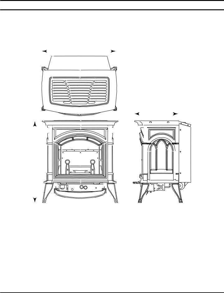
DIMENSIONS
A
C
B
Figure 2 - Dimensions
|
CSVF20S |
CSVF30S |
|
|
|
A |
211/4" |
263/4" |
B |
23" |
281/2" |
C |
161/2" |
193/4" |
6 |
58D6002 |
GETTING STARTED
MAKE SURE YOU HAVE RECEIVED ALL PARTS:
Check your packing list to verify that all listed parts have been received. You should have the following:
•Cast Iron Stove with Burner Assembly
•Installation/Operating Instructions
•Ceramic Fiber Logs
•Touch-up Paint
Millivolt controlled heater designed to be operated with optional devices for ON/OFF functions.
•Hand-Held Remote with Receiver, Manual or Thermostat
•Wall Switch with 15' Wire
•Wall T-stat with 15' Wire
•Stove Mounted Thermostat Control
CAUTION
Gloves are recommended when handling ceramic fiber logs to prevent skin irritation from loose fibers. Logs are fragile--handle with care.
Carefully inspect the contents for shipping damage. If any parts are missing or damaged, immediately inform the dealer from whom you purchased the appliance. Do not attempt to install any part of the appliance unless you have all parts in good condition.
WHAT YOU WILL NEED FOR INSTALLATION:
You must have the following items available before proceeding with installation:
•External regulator (for propane/L.P.G.)
or high pressure natural gas (1 to 2 PSI system)
•Piping which complies with local codes
•Sediment trap (recommended)
•Pipe wrench or appropriate wrench set
•Pipe sealant approved for use with propane/L.P.G. (Resistant to sulfur compounds)
•Manual shutoff valve
•Tee joint
•Screwdrivers
58D56002 |
7 |

PRODUCT SPECIFICATIONS
NATURAL GAS
NOTE: An external regulator is required to reduce supply pressure to a maximum of 101/2" w.c. on Natural Gas systems operating at higher pressure.
MILLIVOLT PRESSURE |
|
|
|
|
|
Regulator Pressure Setting: |
3.5" w.c. |
|
|
|
|
Pilot Regulator: |
3.5" w.c. |
|
|
|
|
Gas Inlet Pressure: |
Max. 10 1/2" w. c. |
Min. 5" w.c. |
|
||
|
|
|
|
|
|
|
|
|
|
Gas Rate |
|
|
|
|
|
|
|
|
Model Number |
Type |
Max. BTU/Hr |
Min. BTU/Hr |
|
|
|
|
|
|
|
|
CSVF20SNV(G-EBL-ES-EMB) |
Milli-Volt |
10,000 |
6,000 |
|
|
CSVF30SNV(G-EBL-ES-EMB) |
Milli-Volt |
32,000 |
20,000 |
|
|
|
|
|
|
|
PROPANE / LPG
Note: An external regulator is required to reduce supply pressure to a maximum of 13" w.c.
MILLIVOLT PRESSURE |
|
|
|
|
|
Regulator Pressure Setting: |
10" w.c. |
|
|
|
|
Gas Inlet Pressure: |
Maximum 13" w.c. |
|
|
|
|
|
|
Minimum 11" w.c. |
|
|
|
|
|
|
|
|
|
|
|
|
|
Gas Rate |
|
|
|
|
|
|
|
|
Model Number |
Type |
Max. BTU/Hr |
Min. BTU/Hr |
|
|
|
|
|
|
|
|
CSVF20SPV(G-EBL-ES-EMB) |
Milli-Volt |
10,000 |
6,000 |
|
|
CSVF30SPV(G-EBL-ES-EMB) |
Milli-Volt |
32,000 |
26,000 |
|
|
|
|
|
|
|
IGNITION CONTROLS
Piezo ignitor allows ignition of the pilot without the use of matches.
Milli-Volt control has four (4) positions:
OFF |
- |
All gas to the burner is shut off at the valve. |
IGN |
- |
Valve position to light/maintain a standing pilot. |
ON |
- |
Valve position to turn burners ON/OFF with remote switch/thermostat. |
LOW/HI - |
Variable position to control flame height (heat output). Both front and rear burners are in operation to |
|
|
|
provide realistic glow and yellow flame. |
PILOT/ODS
The gas log heater is fitted with a specially designed safety pilot (ODS assembly) light which senses the amount of oxygen available in the room and shuts the gas log heater off if the oxygen level begins to drop below a satisfactory level. The pilot can only be relit when adequate fresh air is available.
THERMAL GENERATOR
The millivolt gas log pilot is fitted with a millivolt thermopile generator to provide power for remote activation.
8 |
58D6002 |

GENERAL INSTALLATION INFORMATION
WARNING
Do not install the heater …
•Where curtains, furniture, clothing, or other flammable objects are less than 42" from the front of the heater.
•In high traffic areas.
•In windy or drafty areas.
CODES
Adhere to all local codes or, in their absence, the latest edition of THE NATIONAL FUEL GAS CODE ANSI Z223.1 or NFPA54 which can be obtained from…
American National Standards Institute, Inc.
1430 Broadway
New York, NY 10018
or
National Fire Protection Association, Inc.
Batterymarch Park
Quincy, MA 02269
ADEQUATE COMBUSTION AND VENTILATION AIR
This heater shall not be installed in a confined space or unusually tight construction unless provisions are provided for adequate combustion and ventilation air.
The National Fuel Gas Code, (ANSI Z223.1/NFPA54), defines a confined space as a space whose volume is less than 50 cubic feet per 1,000 BTU per hour (4.8 m3 per kw) of the aggregate input rating of all appliances installed in that space and an unconfined space as a space whose volume is not less than 50 cubic feet per 1,000 BTU per hour (4.8 m3 per kw) of the aggregate input rating of all appliances installed in that space. Rooms communicating directly with the space in which the appliances are installed, through openings not furnished with doors, are considered a part of the unconfined space.
UNUSUALLY TIGHT CONSTRUCTION IS DEFINED AS CONSTRUCTION WHERE…
a)walls and ceilings exposed to the outside atmosphere have a continuous water vapor retarder with a rating of 1 perm (6 x 10¹¹ kg per pa-sec-m2) or less with openings gasketed or sealed;
b)weather stripping has been added on openable windows and doors, and
c)caulking or sealants are applied to areas such as joints around window and door frames, between sole plates and floors, between wall-ceiling joints, between wall panels, at penetrations for plumbing, electrical, and gas lines, and at other openings.
58D56002 |
9 |
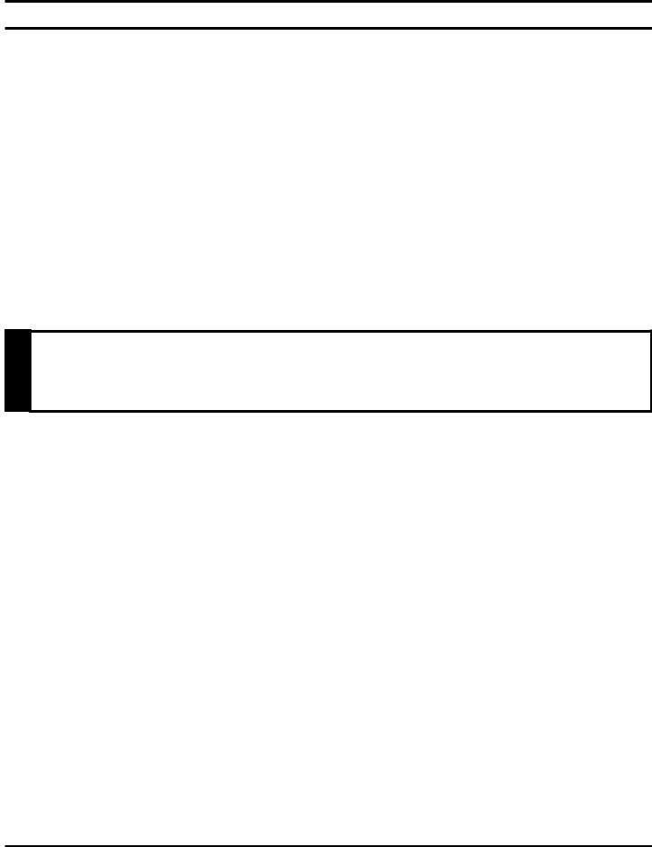
GENERAL INSTALLATION INFORMATION
Counter
Cast Iron Stove
L 2
L 1
H
W
Figure 3 - Example of a Large Room with 1/2 Wall Divider
The following formula can be used to determine the maximum heater rating per the definition of unconfined space:
BTU/Hr = (L1 |
+ L |
2) Ft x (W) Ft x (H) Ft |
x 1000 |
|
|||
50 |
|
||
Consider two connecting rooms with an open area between, with the following dimensions:
L1 = 151/2 Ft., L2 = 12 Ft., W = 12 Ft., H = 8 Ft.
BTU/Hr = (151/2 |
+ 12) x (12) x (8) |
x 1000 = 52800 BTU/Hr |
|
||
50 |
|
|
If there were a door between the two rooms the calculation would be based only on the room with the heater.
BTU/Hr = (151/2) x (12) x (8) x 1000 = 29760 BTU/Hr 50
WARNING
If the area in which the heater may be operated is smaller than that defined as an unconfined space or if the building is of unusually tight construction, provide adequate combustion and ventilation air by one of the methods described in the National Fuel Gas Code, ANSI Z223.1, NFPA54, Section 5.3 or applicable local codes.
10 |
58D6002 |
 Loading...