


 Loading...
Type QD75P/QD75D Positioning Module
User's Manual
Mitsubishi Programmable
Logic Controller
QD75P1
QD75P2
QD75P4
QD75D1
QD75D2
QD75D4

 SAFETY INSTRUCTIONS
(Always read these instructions before using this equipment.)
Before using this product, please read this manual and the relevant manuals introduced in this manual carefully and pay full attention to safety to handle the product correctly.
The instructions given in this manual are concerned with this product. For the safety instructions of the programmable logic controller system, please read the CPU module User's Manual.
In this manual, the safety instructions are ranked as "DANGER" and "CAUTION".
!DANGER
!CAUTION
Indicates that incorrect handling may cause hazardous conditions, resulting in death or severe injury.
Indicates that incorrect handling may cause hazardous conditions, resulting in medium or slight personal injury or physical damage.
Note that the ! CAUTION level may lead to a serious consequence according to the circumstances. Always follow the instructions of both levels because they are important to personal safety.
Please save this manual to make it accessible when required and always forward it to the end user.
[Design Instructions]
! DANGER
 Provide a safety circuit outside the programmable logic controller so that the entire system will operate safely even when an external power supply error or PLC fault occurs.
Failure to observe this could lead to accidents for incorrect outputs or malfunctioning.
(1)Configure an emergency stop circuit and interlock circuit such as a positioning upper limit/lower limit to prevent mechanical damage outside the PLC.
(2)The machine OPR operation is controlled by the OPR direction and OPR speed data. Deceleration starts when the near-point dog turns ON. Thus, if the OPR direction is incorrectly set, deceleration will not start and the machine will continue to travel. Configure an interlock circuit to prevent mechanical damage outside the PLC.
(3)When the module detects an error, normally deceleration stop or sudden stop will take place according to the parameter stop group settings.
Set the parameters to the positioning system specifications.
Make sure that the OPR parameter and positioning data are within the parameter setting values.
A - 1
[Design Instructions]
! CAUTION
 Do not bundle or adjacently lay the control wire or communication cable with the main circuit or power wire.
Separate these by 100mm (3.94in.) or more.
Failure to observe this could lead to malfunctioning caused by noise.
[Mounting Instructions]
! CAUTION
 Use the PLC within the general specifications environment given in this manual.
Using the PLC outside the general specification range environment could lead to electric shocks, fires, malfunctioning, product damage or deterioration.
 While pressing the installation lever located at the bottom of module, insert the module fixing tab into the fixing hole in the base unit until it stops. Then, securely mount the module with the fixing hole as a supporting point.
Incorrect loading of the module can cause a malfunction, failure or drop.
When using the PLC in the environment of much vibration, tighten the module with a screw. Tighten the screw in the specified torque range.
Undertightening can cause a drop, short circuit or malfunction.
Overtightening can cause a drop, short circuit or malfunction due to damage to the screw or module.
 Completely turn off the externally supplied power used in the system before mounting or removing the module.
Not doing so may damage the product.
[Wiring Instructions]
! DANGER
 Always confirm the terminal layout before connecting the wires to the module.
[Startup/Maintenance Instructions]
! DANGER
 Completely turn off the externally supplied power used in the system before cleaning or tightening the screws.
Failure to turn all phases OFF could lead to electric shocks.
A - 2
[Startup/Maintenance Instructions]
! CAUTION
 Never disassemble or modify the module.
Failure to observe this could lead to trouble, malfunctioning, injuries or fires.
 Completely turn off the externally supplied power used in the system before installing or removing the module.
Failure to turn all phases OFF could lead to module trouble or malfunctioning.
 Do not mount/remove the module onto/from the base unit more than 50 times (IEC61131-2- compliant), after the first use of the product. Failure to do so may cause malfunction.
 Before starting test operation, set the parameter speed limit value to the slowest value, and make sure that operation can be stopped immediately if a hazardous state occurs.
 Always make sure to touch the grounded metal to discharge the electricity charged in the body, etc., before touching the module.
Failure to do so may cause a failure or malfunctions of the module.
[Precautions for use]
! CAUTION
 Note that when the reference axis speed is designated for interpolation operation, the speed of the partner axis (2nd axis, 3rd axis and 4th axis) may be larger than the set speed (larger than the speed limit value).
[Disposal Instructions]
! CAUTION
 When disposing of the product, handle it as industrial waste.
A - 3

REVISIONS
|
|
The manual number is given on the bottom left of the back cover. |
||
Print Date |
Manual Number |
Revision |
||
Dec., 1999 |
SH (NA)-080058-A |
First edition |
||
Oct., 2000 |
SH (NA)-080058-B |
Addition of function version B |
||
|
|
(Overall revisions based on the Japanese Manual Version |
||
|
|
SH-080047-E) |
||
Jun., 2001 |
SH (NA)-080058-C |
The software package names (GPP function software package, |
||
|
|
QD75 software package) have been replaced by the product names |
||
|
|
(GX Developer, GX Configurator-QP) for standardization. |
||
|
|
|
|
|
|
|
Partial corrections and additions |
|
|
|
|
CONTENTS, About Manuals, Generic Terms and Abbreviations, |
||
|
|
Section 1.4, Section 2.2, Section 2.3, Section 3.2.2 to Section 3.2.4, |
||
|
|
Section 3.3.2, Section 3.3.3, Section 3.4.1, Section 3.4.3, Section |
||
|
|
3.4.4, Section 4.1.2, Section 4.3, Section 5.1.2, Section 5.1.3, Section |
||
|
|
5.2.3, Section 5.2.5, Section 5.6.2, Section 5.7.1, Section 6.2 to |
||
|
|
Section 6.4, Section 6.5.3, Section 7.2, Section 8.2.2, Section 8.2.5, |
||
|
|
Section 8.2.6, Section 9.1.2, Section 9.2.1, Section 9.2.16, Section |
||
|
|
9.2.17, Section 10.3.2, Section 10.6.2, Section 11.2.3, Section 11.3.3, |
||
|
|
Section 11.3.4, Section 11.4.3, Section 12.1.1, Section 12.5 to Section |
||
|
|
12.7, Section 13.1, Section 13.3, Section 13.4, Section 14.2 to Section |
||
|
|
14.7, Section 15.1, Section 15.2, Section 15.4, Appendix 1, Appendix |
||
|
|
9.2, Appendix 11, INDEX |
||
|
|
|
|
|
Apr., 2003 |
SH (NA)-080058-D |
|
|
|
Partial corrections and additions |
|
|||
|
|
SAFETY INSTRUCTIONS, CONTENTS, Component List, |
||
|
|
Section 1.2.3, Section 1.4, Section 2.3, Section 2.4, Section 3.1, |
||
|
|
Section 3.2.1, Section 3.2.3, Section 3.2.4, Section 3.4.1, Section |
||
|
|
3.4.4, Section 4.1.2, Section 4.3.1, Section 4.3.2, Section 5.1.1, |
||
|
|
Section 5.1.7, Section 5.1.8, Section 5.2.1, Section 5.2.4, Section |
||
|
|
5.6.2, Section 5.7.1, Section 6.4, Section 6.5.4, Section 6.5.6, Section |
||
|
|
8.2.3 to Section 8.2.8, Section 9.2.17, Section 9.2.19, Section 11.2.1, |
||
|
|
Section 11.3.1, Section 11.4.1, Section 12.1.1, Section 12.5.1, Section |
||
|
|
12.5.2, Section 12.7.3, Section 12.7.5, Section 12.7.9, Section 14.4, |
||
|
|
Section 15.2, Appendix 1.1, Appendix 4.1 to Appendix 4.3, Appendix |
||
|
|
7.1, Appendix 9.2, Appendix 10 to Appendix 13, INDEX |
||
|
|
|
|
|
Oct., 2003 |
SH (NA)-080058-E |
|
|
|
Partial corrections and additions |
|
|||
|
|
CONTENTS, Section 1.1.1, Section 1.4, Section 2.2, Section 2.4, |
||
|
|
Section 3.2.1, Section 3.2.3, Section 3.2.4, Section 3.3.2, Section |
||
|
|
3.4.3, Section 3.4.4, Section 5.1.1, Section 5.1.8, Section 5.7.1, |
||
|
|
Section 6.5.3, Section 6.5.6, Section 7.1.2, Section 9.1.2, Section |
||
|
|
9.2.3 to Section 9.2.9, Section 11.2.1, Section 11.3.1, Section 11.4.1, |
||
|
|
Section 12.2.1, Section 12.7.10, Appendix 9.2, Appendix 12, INDEX |
||
|
|
|
|
|
A - 4

REVISIONS
|
|
The manual number is given on the bottom left of the back cover. |
||
Print Date |
Manual Number |
Revision |
||
Feb., 2004 |
SH (NA)-080058-F |
|
|
|
Partial corrections and additions |
|
|||
|
|
CONTENTS, Section 3.4.1, Section 3.4.3, Section 3.4.4, |
||
|
|
Section 5.2.1, Section 5.4, Section 5.5, Section 5.6.2, Section 8.2.6, |
||
|
|
Section 10.1.2, Section 10.3.3, Section 10.3.5, Section 10.3.7, |
||
|
|
Appendix 9.2, Appendix 12 |
||
|
|
|
|
|
Nov., 2004 |
SH (NA)-080058-G |
|
|
|
Partial corrections and additions |
|
|||
|
|
SAFETY INSTRUCTIONS, Section 1.4, Section 2.3, Section 2.4, |
||
|
|
Section 4.2.1, Section 4.3.1, Section 4.5.1, Section 5.1.7, |
||
|
|
Section 5.2.1, Section 5.2.6, Section 5.6.2, Section 6.1, |
||
|
|
Section 9.2.19, Section 12.2.1, Section 12.4.4, Section 12.7.4, |
||
|
|
Appendix 1.1, Appendix 9.1 |
||
Jun., 2005 |
SH (NA)-080058-H |
|
|
|
Partial corrections and additions |
|
|||
|
|
Section 5.1.2, Section 9.1.2, Section 9.2.10, Section 9.2.21, |
||
|
|
Section 10.3.8, Section 11.4.1, Section 12.5.2, Section 12.7.1, |
||
|
|
Section 12.7.6, Section 15.1, Section 15.2 |
||
|
|
|
|
|
|
|
|
|
|
Japanese Manual Version SH-0800047-L
This manual confers no industrial property rights or any rights of any other kind, nor does it confer any patent licenses. Mitsubishi Electric Corporation cannot be held responsible for any problems involving industrial property rights which may occur as a result of using the contents noted in this manual.
1999 MITSUBISHI ELECTRIC CORPORATION
A - 5
INTRODUCTION
Thank you for purchasing the Mitsubishi general-purpose programmable logic controller MELSEC-Q Series. Always read through this manual, and fully comprehend the functions and performance of the Q Series PLC before starting use to ensure correct usage of this product.
|
CONTENTS |
|
|
|
SAFETY INSTRUCTIONS............................................................................................................................. |
|
A- 1 |
||
REVISIONS.................................................................................................................................................... |
|
A- 4 |
||
INTRODUCTION ........................................................................................................................................... |
|
A- 6 |
||
CONTENTS.................................................................................................................................................... |
|
A- 6 |
||
About Manuals .............................................................................................................................................. |
|
A- 13 |
||
Using This Manual......................................................................................................................................... |
|
A- 13 |
||
Conformation to the EMC AND LOW-VOLTAGE DIRECTIVES................................................................. |
|
A- 13 |
||
Generic Terms and Abbreviations................................................................................................................ |
|
A- 14 |
||
Component List ............................................................................................................................................. |
|
A- 15 |
||
|
|
|
|
|
Section 1 Product Specifications and Handling |
|
|
|
|
|
|
|
||
1. Product Outline |
1- |
1 to 1- 22 |
||
|
|
|
|
|
1.1 |
Positioning control.................................................................................................................................... |
|
1- |
2 |
1.1.1 Features of QD75.............................................................................................................................. |
|
1- 2 |
||
1.1.2 Purpose and applications of positioning control............................................................................... |
|
1- |
5 |
|
1.1.3 Mechanism of positioning control ..................................................................................................... |
|
1- |
7 |
|
1.1.4 Outline design of positioning system................................................................................................ |
|
1- |
9 |
|
1.1.5 Communicating signals between QD75 and each module............................................................. |
|
1- 12 |
||
1.2 |
Flow of system operation........................................................................................................................ |
|
1- 15 |
|
1.2.1 Flow of all processes........................................................................................................................ |
|
1- 15 |
||
1.2.2 Outline of starting ............................................................................................................................. |
|
1- 18 |
||
1.2.3 Outline of stopping ........................................................................................................................... |
|
1- 20 |
||
1.2.4 Outline for restarting......................................................................................................................... |
|
1- 21 |
||
1.3 |
Restrictions with a system using a stepping motor................................................................................ |
|
1- 22 |
|
1.4 |
Function additions/modifications according to function version B......................................................... |
|
1- 22 |
|
|
|
|
|
|
2. System Configuration |
2- |
1 to 2- |
6 |
|
2.1 |
General image of system......................................................................................................................... |
|
2- 2 |
|
2.2 |
Component list ......................................................................................................................................... |
|
2- |
4 |
2.3 |
Applicable system .................................................................................................................................... |
|
2- |
5 |
2.4 |
How to check the function version and SERIAL No. ............................................................................. 2- |
6 |
||
A - 6

3. Specifications and Functions |
3- |
1 to 3- 24 |
||
3.1 |
Performance specifications...................................................................................................................... |
|
3- |
2 |
3.2 |
List of functions ....................................................................................................................................... |
|
3- |
4 |
3.2.1 QD75 control functions...................................................................................................................... |
|
3- |
4 |
|
3.2.2 QD75 main functions......................................................................................................................... |
|
3- 6 |
||
3.2.3 QD75 sub functions and common functions .................................................................................... |
|
3- 8 |
||
3.2.4 Combination of QD75 main functions and sub functions................................................................ |
|
3- 12 |
||
3.3 |
Specifications of input/output signals with PLC CPU............................................................................. |
|
3- 14 |
|
3.3.1 List of input/output signals with PLC CPU....................................................................................... |
|
3- 14 |
||
3.3.2 Details of input signals (QD75 PLC CPU) .................................................................................. |
|
3- 15 |
||
3.3.3 Details of output signals (PLC CPU QD75) ................................................................................ |
|
3- 16 |
||
3.4 |
Specifications of input/output interfaces with external devices ............................................................. |
|
3- 17 |
|
3.4.1 Electrical specifications of input/output signals............................................................................... |
|
3- 17 |
||
3.4.2 Signal layout for external device connection connector.................................................................. |
|
3- 19 |
||
3.4.3 List of input/output signal details...................................................................................................... |
|
3- 20 |
||
3.4.4 Input/output interface internal circuit................................................................................................ |
|
3- 22 |
||
|
|
|
|
|
4. Installation, Wiring and Maintenance of the Product |
4- |
1 to 4- |
16 |
|
4.1 |
Outline of installation, wiring and maintenance....................................................................................... |
|
4- |
2 |
4.1.1 Installation, wiring and maintenance procedures............................................................................. |
|
4- |
2 |
|
4.1.2 Names of each part........................................................................................................................... |
|
4- 3 |
||
4.1.3 Handling precautions ........................................................................................................................ |
|
4- |
5 |
|
4.2 |
Installation ................................................................................................................................................ |
|
4- |
7 |
4.2.1 Precautions for installation................................................................................................................ |
|
4- |
7 |
|
4.3 Wiring........................................................................................................................................................ |
|
4- |
8 |
|
4.3.1 Precautions for wiring........................................................................................................................ |
|
4- |
8 |
|
4.3.2 Wiring of the differential driver common terminal............................................................................ |
|
4- 13 |
||
4.4 |
Confirming the installation and wiring..................................................................................................... |
|
4- 14 |
|
4.4.1 Items to confirm when installation and wiring are completed ......................................................... |
|
4- 14 |
||
4.5 |
Maintenance............................................................................................................................................ |
|
4- 15 |
|
4.5.1 Precautions for maintenance........................................................................................................... |
|
4- 15 |
||
4.5.2 Disposal instructions ........................................................................................................................ |
|
4- 15 |
||
|
|
|
||
5. Data Used for Positioning Control (List of buffer memory addresses) |
5- |
1 to 5-132 |
||
5.1 |
Types of data............................................................................................................................................ |
|
5- |
2 |
5.1.1 Parameters and data required for control......................................................................................... |
|
5- |
2 |
|
5.1.2 Setting items for positioning parameters.......................................................................................... |
|
5- |
4 |
|
5.1.3 Setting items for OPR parameters.................................................................................................... |
|
5- |
6 |
|
5.1.4 Setting items for positioning data...................................................................................................... |
|
5- |
7 |
|
5.1.5 Setting items for block start data ..................................................................................................... |
|
5- 10 |
||
5.1.6 Setting items for condition data ....................................................................................................... |
|
5- 11 |
||
5.1.7 Types and roles of monitor data ...................................................................................................... |
|
5- 12 |
||
5.1.8 Types and roles of control data ....................................................................................................... |
|
5- 16 |
||
A - 7
5.2 |
List of parameters ................................................................................................................................... |
5- 20 |
|
5.2.1 Basic parameters 1 .......................................................................................................................... |
5- 20 |
||
5.2.2 Basic parameters 2 .......................................................................................................................... |
5- 26 |
||
5.2.3 Detailed parameters 1...................................................................................................................... |
5- 28 |
||
5.2.4 Detailed parameters 2...................................................................................................................... |
5- 36 |
||
5.2.5 OPR basic parameters..................................................................................................................... |
5- 46 |
||
5.2.6 OPR detailed parameters ................................................................................................................ |
5- 54 |
||
5.3 |
List of positioning data ............................................................................................................................ |
5- 58 |
|
5.4 |
List of block start data ............................................................................................................................. |
5- 74 |
|
5.5 |
List of condition data ............................................................................................................................... |
5- 80 |
|
5.6 |
List of monitor data.................................................................................................................................. |
5- 86 |
|
5.6.1 System monitor data ........................................................................................................................ |
5- 86 |
||
5.6.2 Axis monitor data.............................................................................................................................. |
5- 96 |
||
5.7 |
List of control data.................................................................................................................................. |
5-110 |
|
5.7.1 System control data......................................................................................................................... |
5-110 |
||
5.7.2 Axis control data.............................................................................................................................. |
5-112 |
||
|
|
||
6. Sequence Program Used for Positioning Control |
6- 1 to 6- 44 |
||
|
|
|
|
6.1 |
Precautions for creating program ............................................................................................................ |
6- |
2 |
6.2 |
List of devices used.................................................................................................................................. |
6- |
5 |
6.3 |
Creating a program ................................................................................................................................. |
6- 11 |
|
6.3.1 General configuration of program.................................................................................................... |
6- 11 |
||
6.3.2 Positioning control operation program............................................................................................. |
6- 12 |
||
6.4 |
Positioning program examples ............................................................................................................... |
6- 15 |
|
6.5 |
Program details ....................................................................................................................................... |
6- 24 |
|
6.5.1 Initialization program ........................................................................................................................ |
6- 24 |
||
6.5.2 Start details setting program............................................................................................................ |
6- 25 |
||
6.5.3 Start program.................................................................................................................................... |
6- 27 |
||
6.5.4 Continuous operation interrupt program.......................................................................................... |
6- 37 |
||
6.5.5 Restart program ............................................................................................................................... |
6- 39 |
||
6.5.6 Stop program.................................................................................................................................... |
6- 42 |
||
|
|
||
7. Memory Configuration and Data Process |
7- 1 to 7- 12 |
||
7.1 |
Configuration and roles of QD75 memory............................................................................................... |
7- 2 |
|
7.1.1 Configuration and roles of QD75 memory........................................................................................ |
7- 2 |
||
7.1.2 Buffer memory area configuration .................................................................................................... |
7- |
5 |
|
7.2 |
Data transmission process ...................................................................................................................... |
7- |
6 |
A - 8
Section 2 Control Details and Setting
8. OPR Control |
8- 1 to 8- 22 |
|
8.1 Outline of OPR control............................................................................................................................. |
8- |
2 |
8.1.1 Two types of OPR control................................................................................................................. |
8- 2 |
|
8.2 Machine OPR........................................................................................................................................... |
8- 4 |
|
8.2.1 Outline of the machine OPR operation............................................................................................. |
8- |
4 |
8.2.2 Machine OPR method....................................................................................................................... |
8- 5 |
|
8.2.3 OPR method (1): Near-point dog method ........................................................................................ |
8- 6 |
|
8.2.4 OPR method (2): Stopper method 1) ............................................................................................... |
8- 8 |
|
8.2.5 OPR method (3): Stopper method 2) .............................................................................................. |
8- 11 |
|
8.2.6 OPR method (4): Stopper method 3) .............................................................................................. |
8- 14 |
|
8.2.7 OPR method (5): Count method 1).................................................................................................. |
8- 16 |
|
8.2.8 OPR method (6): Count method 2).................................................................................................. |
8- 18 |
|
8.3 Fast OPR................................................................................................................................................. |
8- 20 |
|
8.3.1 Outline of the fast OPR operation.................................................................................................... |
8- 20 |
|
|
|
|
9. Major Positioning Control |
9- 1 to 9-114 |
|
9.1 Outline of major positioning controls ....................................................................................................... |
9- |
2 |
9.1.1 Data required for major positioning control ...................................................................................... |
9- |
4 |
9.1.2 Operation patterns of major positioning controls ............................................................................. |
9- |
5 |
9.1.3 Designating the positioning address................................................................................................ |
9- 15 |
|
9.1.4 Confirming the current value............................................................................................................ |
9- 16 |
|
9.1.5 Control unit "degree" handling ......................................................................................................... |
9- 18 |
|
9.1.6 Interpolation control.......................................................................................................................... |
9- 21 |
|
9.2 Setting the positioning data ................................................................................................................... |
9- 25 |
|
9.2.1 Relation between each control and positioning data ...................................................................... |
9- 25 |
|
9.2.2 1-axis linear control .......................................................................................................................... |
9- 27 |
|
9.2.3 2-axis linear interpolation control..................................................................................................... |
9- 29 |
|
9.2.4 3-axis linear interpolation control..................................................................................................... |
9- 33 |
|
9.2.5 4-axis linear interpolation control..................................................................................................... |
9 -39 |
|
9.2.6 1-axis fixed-feed control................................................................................................................... |
9- 43 |
|
9.2.7 2-axis fixed-feed control (interpolation) ........................................................................................... |
9- 45 |
|
9.2.8 3-axis fixed-feed control (interpolation) ........................................................................................... |
9- 47 |
|
9.2.9 4-axis fixed-feed control (interpolation) .......................................................................................... |
9- 51 |
|
9.2.10 2-axis circular interpolation control with sub point designation..................................................... |
9- 53 |
|
9.2.11 2-axis circular interpolation control with center point designation ................................................ |
9- 59 |
|
9.2.12 1-axis speed control....................................................................................................................... |
9- 67 |
|
9.2.13 2-axis speed control....................................................................................................................... |
9- 70 |
|
9.2.14 3-axis speed control....................................................................................................................... |
9- 73 |
|
9.2.15 4-axis speed control....................................................................................................................... |
9- 77 |
|
9.2.16 Speed-position switching control (INC mode)............................................................................... |
9- 82 |
|
9.2.17 Speed-position switching control (ABS mode).............................................................................. |
9- 90 |
|
9.2.18 Position-speed switching control ................................................................................................... |
9- 98 |
|
9.2.19 Current value changing................................................................................................................. |
9-105 |
|
A - 9 |
|
|
9.2.20 NOP instruction ............................................................................................................................. |
|
9-110 |
||
9.2.21 JUMP instruction ........................................................................................................................... |
|
9-111 |
||
9.2.22 LOOP............................................................................................................................................. |
|
9-113 |
||
9.2.23 LEND ............................................................................................................................................. |
|
9-114 |
||
|
|
|
||
10. High-Level Positioning Control |
10- |
1 to 1026 |
||
|
|
|
|
|
10.1 |
Outline of high-level positioning control............................................................................................... |
|
10- |
2 |
10.1.1 Data required for high-level positioning control............................................................................ |
|
10- |
3 |
|
10.1.2 " Block start data" and "condition data" configuration.................................................................. |
|
10- |
4 |
|
10.2 |
High-level positioning control execution procedure ........................................................................... |
|
10- |
6 |
10.3 |
Setting the block start data .................................................................................................................. |
|
10- |
7 |
10.3.1 Relation between various controls and block start data .............................................................. |
|
10- |
7 |
|
10.3.2 Block start (normal start) .............................................................................................................. |
|
10- |
8 |
|
10.3.3 Condition start .............................................................................................................................. |
|
1010 |
||
10.3.4 Wait start....................................................................................................................................... |
|
1011 |
||
10.3.5 Simultaneous start ...................................................................................................................... |
|
1012 |
||
10.3.6 Repeated start (FOR loop) .......................................................................................................... |
|
1013 |
||
10.3.7 Repeated start (FOR condition) .................................................................................................. |
|
1014 |
||
10.3.8 Restrictions when using the NEXT start...................................................................................... |
|
1015 |
||
10.4 |
Setting the condition data ................................................................................................................... |
|
1016 |
|
10.4.1 Relation between various controls and the condition data ......................................................... |
|
1016 |
||
10.4.2 Condition data setting examples ................................................................................................. |
|
1019 |
||
10.5 |
Multiple axes simultaneous start control ............................................................................................ |
|
1020 |
|
10.6 |
Start program for high-level positioning control ................................................................................. |
|
1023 |
|
10.6.1 Starting high-level positioning control.......................................................................................... |
|
1023 |
||
10.6.2 Example of a start program for high-level positioning control..................................................... |
|
1024 |
||
|
|
|
||
11. Manual Control |
11- |
1 to 1136 |
||
11.1 |
Outline of manual control .................................................................................................................... |
|
11- |
2 |
11.1.1 Three manual control methods..................................................................................................... |
|
11- 2 |
||
11.2 |
JOG operation...................................................................................................................................... |
|
11- 4 |
|
11.2.1 Outline of JOG operation .............................................................................................................. |
|
11- |
4 |
|
11.2.2 JOG operation execution procedure ............................................................................................ |
|
11- 7 |
||
11.2.3 Setting the required parameters for JOG operation..................................................................... |
|
11- |
8 |
|
11.2.4 Creating start programs for JOG operation................................................................................. |
|
1110 |
||
11.2.5 JOG operation example............................................................................................................... |
|
1113 |
||
11.3 |
Inching operation................................................................................................................................. |
|
1117 |
|
11.3.1 Outline of inching operation ......................................................................................................... |
|
1117 |
||
11.3.2 Inching operation execution procedure ....................................................................................... |
|
1120 |
||
11.3.3 Setting the required parameters for inching operation................................................................ |
|
1121 |
||
11.3.4 Creating a program to enable/disable the inching operation...................................................... |
|
1122 |
||
11.3.5 Inching operation example........................................................................................................... |
|
1125 |
||
11.4 |
Manual pulse generator operation...................................................................................................... |
|
1127 |
|
11.4.1 Outline of manual pulse generator operation.............................................................................. |
|
1127 |
||
11.4.2 Manual pulse generator operation execution procedure ............................................................ |
|
1131 |
||
11.4.3 Setting the required parameters for manual pulse generator operation .................................... |
|
1132 |
||
|
A - 10 |
|
|
|
11.4.4 Creating a program to enable/disable the manual pulse generator operation |
.......................... |
1133 |
||
|
|
|
||
12. Control Sub Functions |
12 - |
1 to 1298 |
||
|
|
|
|
|
12.1 |
Outline of sub functions ....................................................................................................................... |
|
12- |
2 |
12.1.1 Outline of sub functions................................................................................................................. |
|
12- |
2 |
|
12.2 |
Sub functions specifically for machine OPR ....................................................................................... |
|
12- |
4 |
12.2.1 OPR retry function......................................................................................................................... |
|
12- |
4 |
|
12.2.2 OP shift function ........................................................................................................................... |
|
12- |
8 |
|
12.3 |
Functions for compensating the control ............................................................................................. |
|
1211 |
|
12.3.1 Backlash compensation function................................................................................................. |
|
1211 |
||
12.3.2 Electronic gear function................................................................................................................ |
|
1213 |
||
12.3.3 Near pass function ....................................................................................................................... |
|
1218 |
||
12.4 |
Functions to limit the control............................................................................................................... |
|
1221 |
|
12.4.1 Speed limit function...................................................................................................................... |
|
1221 |
||
12.4.2 Torque limit function..................................................................................................................... |
|
1223 |
||
12.4.3 Software stroke limit function....................................................................................................... |
|
1226 |
||
12.4.4 Hardware stroke limit function ..................................................................................................... |
|
1232 |
||
12.5 |
Functions to change the control details.............................................................................................. |
|
1234 |
|
12.5.1 Speed change function ................................................................................................................ |
|
1234 |
||
12.5.2 Override function.......................................................................................................................... |
|
1241 |
||
12.5.3 Acceleration/deceleration time change function ......................................................................... |
|
1244 |
||
12.5.4 Torque change function ............................................................................................................... |
|
1248 |
||
12.6 |
Absolute position restoration function ................................................................................................ |
|
1250 |
|
12.7 |
Other functions.................................................................................................................................... |
|
1258 |
|
12.7.1 Step function................................................................................................................................. |
|
1258 |
||
12.7.2 Skip function................................................................................................................................. |
|
1263 |
||
12.7.3 M code output function................................................................................................................. |
|
1266 |
||
12.7.4 Teaching function......................................................................................................................... |
|
1270 |
||
12.7.5 Target position change function................................................................................................... |
|
1277 |
||
12.7.6 Command in-position function ..................................................................................................... |
|
1281 |
||
12.7.7 Acceleration/deceleration processing function............................................................................ |
|
1284 |
||
12.7.8 Pre-reading start function............................................................................................................. |
|
1287 |
||
12.7.9 Deceleration start flag function .................................................................................................... |
|
1292 |
||
12.7.10 Stop command processing for deceleration stop function........................................................ |
|
1296 |
||
|
|
|||
13. Common Functions |
13 - 1 to 13- 8 |
|||
13.1 |
Outline of common functions............................................................................................................... |
|
13- 2 |
|
13.2 |
Parameter initialization function........................................................................................................... |
|
13- |
3 |
13.3 |
Execution data backup function........................................................................................................... |
|
13- |
5 |
13.4 |
External I/O signal logic switching function......................................................................................... |
|
13- |
7 |
13.5 |
External I/O signal monitor function .................................................................................................... |
|
13- |
8 |
|
|
|
||
14. Dedicated instructions |
14 - |
1 to 1422 |
||
|
|
|
|
|
14.1 |
List of dedicated instructions ............................................................................................................... |
|
14- |
2 |
14.2 |
Interlock during dedicated instruction is executed.............................................................................. |
|
14- |
2 |
14.3 ABRST1, ABRST2, ABRST3, ABRST4.............................................................................................. |
|
14- 3 |
||
|
A - 11 |
|
|
|

14.4 PSTRT1, PSTRT2, PSTRT3, PSTRT4............................................................................................... |
|
|
|
14- 8 |
|
14.5 TEACH1, TEACH2, TEACH3, TEACH4 ............................................................................................ |
|
|
|
1412 |
|
14.6 PFWRT................................................................................................................................................ |
|
|
|
1416 |
|
14.7 PINIT ................................................................................................................................................... |
|
|
|
1420 |
|
|
|
|
|
|
|
15. Troubleshooting |
|
|
|
15- 1 to 1538 |
|
|
|
|
|
|
|
15.1 Error and warning details..................................................................................................................... |
|
|
|
15- |
2 |
15.2 List of errors ......................................................................................................................................... |
|
|
|
15- |
6 |
15.3 List of warnings ................................................................................................................................... |
|
|
|
1532 |
|
15.4 LED display functions ......................................................................................................................... |
|
|
|
1538 |
|
|
|
|
|
||
Appendices |
|
|
Appendix- 1 to Appendix-108 |
||
Appendix 1 Version up of the functions............................................................................................ |
|
|
|
Appendix- |
2 |
Appendix 1.1 Comparison of functions according to function versions....................................... |
Appendix- |
2 |
|||
Appendix 2 Format sheets................................................................................................................ |
|
|
|
Appendix- 4 |
|
Appendix 2.1 Positioning Module operation chart ....................................................................... |
Appendix- |
4 |
|||
Appendix 2.2 Parameter setting value entry table ....................................................................... |
Appendix- |
6 |
|||
Appendix 2.3 Positioning data setting value entry table ............................................................ |
Appendix12 |
||||
Appendix 3 Positioning data (No. 1 to 600) List of buffer memory addresses............................... |
Appendix13 |
||||
Appendix 4 Connection examples with servo amplifiers manufactured by MITSUBISHI Electric Corporation |
|
||||
....................................................................................................................................... |
|
|
|
Appendix37 |
|
Appendix 4.1 Connection example of QD75D |
and MR-H A (Differential driver) ............... |
Appendix37 |
|||
Appendix 4.2 Connection example of QD75D |
and MR-J2/J2S- A (Differential driver) ..... |
Appendix38 |
|||
Appendix 4.3 Connection example of QD75D |
and MR-C A (Differential driver) ............... |
Appendix39 |
|||
Appendix 5 Connection examples with stepping motors manufactured by ORIENTALMOTOR Co., Ltd. |
|
||||
....................................................................................................................................... |
|
|
|
Appendix40 |
|
Appendix 5.1 Connection example of QD75P |
and VEXTA UPD (Open collector)................ |
Appendix40 |
|||
Appendix 6 Connection examples with servo amplifiers manufactured by Matsushita Electric Industrial Co., |
|
||||
Ltd. ................................................................................................................................ |
|
|
|
Appendix41 |
|
Appendix 6.1 Connection example of QD75D |
and MINAS-A series (Differential driver)...... |
Appendix41 |
|||
Appendix 7 Connection examples with servo amplifiers manufactured by SANYO DENKI Co., Ltd. |
|
||||
....................................................................................................................................... |
|
|
|
Appendix42 |
|
Appendix 7.1 Connection example of QD75D |
and PYO series (Differential driver).............. |
Appendix42 |
|||
Appendix 8 Connection examples with servo amplifiers manufactured by YASKAWA Electric Corporation |
|
||||
....................................................................................................................................... |
|
|
|
Appendix43 |
|
Appendix 8.1 Connection example of QD75D |
and Σ - |
|
series (Differential driver) |
Appendix43 |
|
|
|||||
|
|||||
Appendix 9 Comparisons with conventional positioning modules.................................................. |
Appendix44 |
||||
Appendix 9.1 Comparisons with A1SD71S2 model.................................................................... |
Appendix44 |
||||
Appendix 9.2 Comparisons with A1SD75P1-S3/A1SD75P2-S3/ A1SD75P3-S3 models......... |
Appendix45 |
||||
Appendix 10 MELSEC Explanation of positioning terms................................................................ |
Appendix68 |
||||
Appendix 11 Positioning control troubleshooting............................................................................ |
|
|
|
Appendix92 |
|
Appendix 12 List of buffer memory addresses................................................................................. |
|
|
|
Appendix-98 |
|
Appendix 13 External dimension drawing...................................................................................... |
|
|
|
Appendix-107 |
|
A - 12
About Manuals
The following manuals are also related to this product.
In necessary, order them by quoting the details in the tables below.
Related Manuals
|
|
|
|
|
|
Manual Name |
Manual Number |
||
|
|
|
|
|
|
(Model Code) |
|||
|
|
|
|
|
|
|
|
||
Type QD75P/QD75D Positioning Module User's Manual |
|
||||||||
(Hardware) |
|
|
|
|
IB-0800063 |
||||
Describes the performance, specifications, I/O interface, component names, and startup procedure of |
|||||||||
(13JQ73) |
|||||||||
the respective positioning modules: QD75P1, QD75P2, QD75P4, QD75D1, QD75D2, and QD75D4. |
|||||||||
|
|||||||||
(The manual is supplied with the module.) |
|
|
|||||||
|
|
|
|
|
|
|
|
||
GX Configurator-QP Operating Manual |
|
|
|||||||
Describes how to use GX Configurator-QP for the following and other purposes: creating data |
SH-080172 |
||||||||
(parameters, positioning data, etc.), sending the data to the module, monitoring the positioning |
(13JU19) |
||||||||
operations, and testing. (The manual is supplied with the software.) |
|
||||||||
|
|
|
|
|
|
|
|
|
|
Using This Manual |
|
|
|
|
|
||||
|
|
|
The symbols used in this manual are shown below. |
|
|||||
|
|
|
|||||||
|
|
|
Pr. |
|
........ |
Symbol indicating positioning parameter and OPR parameter item. |
|||
|
|
|
|||||||
|
|
|
|
|
....... |
Symbol indicating positioning data, block start data and condition |
|||
|
|
|
Da. |
|
|||||
|
|
|
|
|
|
|
data item. |
|
|
|
|
|
Md. |
....... |
Symbol indicating monitor data item. |
|
|||
|
|
|
|
|
|
|
|||
|
|
|
Cd. |
|
....... |
Symbol indicating control data item. |
|
||
(A serial No. is inserted in the  mark.)
 Representation of numerical values used in this manual.
 Buffer memory addresses, error codes and warning codes are represented in decimal.
 X/Y devices are represented in hexadecimal.
 Setting data and monitor data are represented in decimal or hexadecimal. Data ended by "H" are represented in hexadecimal.
(Example) 10.........Decimal 10H ......Hexadecimal
Conformation to the EMC AND LOW-VOLTAGE DIRECTIVES
For details on making Mitsubishi PLC conform to the EMC and Low Voltage Directives when installing it in your product, please refer to Chapter 3, “EMC AND LOW-VOLTAGE DIRECTIVES” of the using PLC CPU module User’s Manual (Hardware).
The CE logo is printed on the rating plate on the main body of the PLC that conforms to the EMC and Low Voltage Directives.
To make this product conform to the EMC and Low Voltage Directives, please refer to Section 4.3.1 "Precautions for wiring".
A - 13
Generic Terms and Abbreviations
|
Unless specially noted, the following generic terms and abbreviations are used in this |
|
|
manual. |
|
|
|
|
Generic term/abbreviation |
|
Details of generic term/abbreviation |
PLC CPU |
|
Generic term for PLC CPU on which QD75 can be mounted. |
QD75 |
|
Generic term for positioning module QD75P1, QD75P2, QD75P4, QD75D1, QD75D2, and |
|
|
QD75D4. |
|
|
The module type is described to indicate a specific module. |
Peripheral device |
|
Generic term for DOS/V personal computer that can run the following "GX Developer" and "GX |
|
|
Configurator-QP". |
GX Configurator-QP |
|
Abbreviation for GX Configurator-QP (SW2D5C-QD75P-E or later). |
|
|
|
GX Developer |
|
Abbreviation for GX Developer (SW4D5C-GPPW-E or later). |
|
|
|
Drive unit (servo amplifier) |
|
Abbreviation for pulse input compatible drive unit (servo amplifier). |
Manual pulse generator |
|
Abbreviation for manual pulse generator (prepared by user). |
DOS/V personal computer |
|
IBM PC/AT® and compatible DOS/V compliant personal computer. |
Personal computer |
|
Generic term for DOS/V personal computer. |
Workpiece |
|
Generic term for moving body such as workpiece and tool, and for various control targets. |
Axis 1, axis 2, axis 3, |
|
Indicates each axis connected to QD75. |
axis 4 |
|
|
|
|
|
1-axis, 2-axis, 3-axis, |
|
Indicates the number of axes. (Example: 2-axis = Indicates two axes such as axis 1 and axis 2, |
4-axis |
|
axis 2 and axis 3, and axis 3 and axis 1.) |
|
|
|
A - 14
Component List
The table below shows the component included in respective positioning modules:
Module name |
Description |
Quantity |
|
QD75P1 |
QD75P1 Positioning Module(1-axis open collector output system) |
1 |
|
QD75P2 |
QD75P2 Positioning Module(2-axes open collector output system) |
1 |
|
QD75P4 |
QD75P4 Positioning Module(4-axes open collector output system) |
1 |
|
QD75D1 |
QD75D1 Positioning Module(1-axis differential driver output system) |
1 |
|
Differential driver common terminal |
1 |
||
|
|||
QD75D2 |
QD75D2 Positioning Module(2-axes differential driver output system) |
1 |
|
Differential driver common terminal |
1 |
||
|
|||
QD75D4 |
QD75D4 Positioning Module(4-axes differential driver output system) |
1 |
|
Differential driver common terminal |
1 |
||
|
A - 15

MEMO
A - 16

Section 1 Product Specifications and Handling
Section 1
Section 1 is configured for the following purposes (1) to (5).
(1)To understand the outline of positioning control, and the QD75 specifications and functions
(2)To carry out actual work such as installation and wiring
(3)To set parameters and data required for positioning control
(4)To create a sequence program required for positioning control
(5)To understand the memory configuration and data transmission process
Read Section 2 for details on each control.
Chapter 1 |
Product outline .............................................................................................. |
1- 1 to 1- |
22 |
Chapter 2 |
System configuration .................................................................................... |
2- 1 to 2- |
6 |
Chapter 3 Specifications and Functions........................................................................ |
3- 1 to 3- |
24 |
|
Chapter 4 Installation, Wiring and Maintenance of the Product ................................... |
4- 1 to 4- |
16 |
|
Chapter 5 Data Used for Positioning Control................................................................ |
5- 1 to 5-132 |
||
Chapter 6 |
Sequence Program Used for Positioning Control........................................ |
6- 1 to 6- 44 |
|
Chapter 7 |
Memory Configuration and Data Process.................................................... |
7- 1 to 7- 12 |
|

MEMO
1
Chapter 1 Product Outline
The purpose and outline of positioning control using QD75 are explained in this chapter. Reading this chapter will help you understand what can be done using the positioning system and which procedure to use for a specific purpose.
By understanding "What can be done", and "Which procedure to use" beforehand, the positioning system can be structured smoothly.
1.1 |
Positioning control ........................................................................................................ |
1- |
2 |
|
|
1.1.1 |
Features of QD75 ........................................................................................... |
1- 2 |
|
|
1.1.2 Purpose and applications of positioning control ............................................ |
1- |
5 |
|
|
1.1.3 Mechanism of positioning control................................................................... |
1- |
7 |
|
|
1.1.4 Outline design of positioning system ............................................................. |
1- |
9 |
|
|
1.1.5 Communicating signals between QD75 and each module .......................... |
1- 12 |
||
1.2 |
Flow of system operation ............................................................................................ |
1- 15 |
||
|
1.2.1 |
Flow of all processes ..................................................................................... |
1- 15 |
|
|
1.2.2 |
Outline of starting........................................................................................... |
1- 18 |
|
|
1.2.3 |
Outline of stopping......................................................................................... |
1- 20 |
|
|
1.2.4 |
Outline for restarting ...................................................................................... |
1- 21 |
|
1.3 |
Restrictions with a system using a stepping motor .................................................... |
1- 22 |
||
1.4 |
Function additions/modifications according to function version B ............................. |
1- 22 |
||
1 - 1

1 PRODUCT OUTLINE
1.1 Positioning control 1.1.1 Features of QD75
The features of the QD75 are shown below.
MELSEC-Q
(1)Availability of one, two, and four axis modules
(a)One, two and four axis modules are available for both the open collector system pulse output (QD75P1, QD75P2, and QD75P4) and differential driver system pulse output (QD75D1, QD75D2, and QD75D4), comprising six different models.
A model is determined by the drive unit type and number of axes. (Refer to Section 2.2.)
(b)For connecting any of the QD75 modules to the base unit, a single slot and 32 dedicated I/O channels are required.
Within the limit imposed by the maximum number of inputs and outputs supported by the PLC CPU, up to 64 modules can be used. (Refer to Section 3.1.)
(2)Wide variety of positioning control functions
(a)A wide variety of positioning control functions essential to any positioning system are supported: positioning to an arbitrary position, fixed-feed control, equal-speed control, and so on. (Refer to Section 5.3 and 9.2.)
1)Up to 600 positioning data items, including such information as positioning addresses, control systems, and operation patterns, can be prepared for each axis.
Using the prepared positioning data, the positioning control is performed independently for each axis. (In addition, such controls as interpolation involving two to four axes and simultaneous startup of multiple axes are possible.)
2)Independent control of each axis can be achieved in linear control mode (executable simultaneously over four axes).
Such control can either be the independent positioning control using a single positioning data or the continuous positioning control enabled by the continuous processing of multiple positioning data.
3)Coordinated control over multiple axes can take the form of either the linear interpolation through the speed or position control of two to four axes or the circular interpolation involving two axes.
Such control can either be the independent positioning control using a single positioning data or the continuous positioning control enabled by the continuous processing of multiple positioning data.
(b)For each positioning data, the user can specify any of the following control systems: position control, speed control, speed-position switching control, position-speed switching control, and so on. (Refer to Section 5.3 and 9.2.)
1 - 2

1 PRODUCT OUTLINE
MELSEC-Q
(c)Continuous positioning control using multiple positioning data can be executed in accordance with the operation patterns the user assigned to the positioning data. (Refer to Section 5.3 and 9.1.2)
Continuous positioning control can be executed over multiple blocks, where each block consists of multiple positioning data. (Refer to Section 10.3.2.)
(d)OPR control is given additional features (Refer to Section 8.2.)
1)Six different machine OPR methods are provided: near point dog method (one method), stopper methods (three methods), and count methods (two methods).
2)OPR retry function facilitates the machine OPR control from an arbitrary position.
(The machine OP a premier reference position for positioning control. The machine is set to the machine OP through one of the machine OPR methods mentioned in 1) above.)
(e)Two acceleration/deceleration control methods are provided: automatic trapezoidal acceleration/deceleration and S-pattern acceleration/deceleration. (Refer to Section 12.7.7.)
(The S-pattern acceleration/deceleration control is disabled if stepping motors are used. Refer to Section 1.3.)
(3)Quick startup (Refer to Section 3.1.)
A positioning operation starts up quickly taking as little as 6 ms to 7 ms. When operation using simultaneous start function or interpolation operation is
executed, the axes start without delay. |
|
(Example) Axis 1 and Axis 3 are started by the |
: No delay in Axis 1 and |
simultaneous start function |
Axis 3 start |
Axis 2 and Axis 4 are started by the |
: No delay in Axis 2 and |
interpolation operation |
Axis 4 start |
(4)Faster pulse output and allowance of longer distance to drive unit (Refer to Section 3.1.)
The modules with a differential driver (QD75D1, QD75D2, and QD75D4) incorporate the improvements in pulse output speed and maximum distance to the drive unit.
•QD75D1/QD75D2/QD75D4: 1 Mpulse/s, 10 m max.
•QD75P1/QD75P2/QD75P4: 200 kpulse/s, 2 m max.
(5)Easy maintenance
Each QD75 positioning module incorporates the following improvements in maintainability:
(a)Data such as the positioning data and parameters can be stored on a flash ROM inside the QD75, eliminating the need of a battery for retaining data. (Refer to Section 7.1.1.)
(b)Error messages are classified in more detail to facilitate the initial troubleshooting procedure. (Refer to Section 15.1.)
(c)The module retains 16 error messages and 16 warning messages recently output, offering more complete error and warning histories.
(Refer to Section 5.6.1.)
1 - 3

1 PRODUCT OUTLINE
MELSEC-Q
(6) Support of intelligent function module dedicated instructions
Dedicated instructions such as the absolute position restoration instruction, positioning start instruction, and teaching instruction are provided.
The use of such dedicated instruction simplifies sequence programs.(Refer to Chapter 14.)
(7) Setups, monitoring, and testing through GX Configurator-QP
Using GX Configurator-QP, the user can control the QD75 parameters and positioning data without having to be conscious of the buffer memory addresses. Moreover, GX Configurator-QP has a test function which allows the user to check the wiring before creating a sequence program for positioning control, or test operation the QD75 using created parameters and positioning data for checking their integrity.
The control monitor function of GX Configurator-QP allows the user to debug programs efficiently.
1 - 4
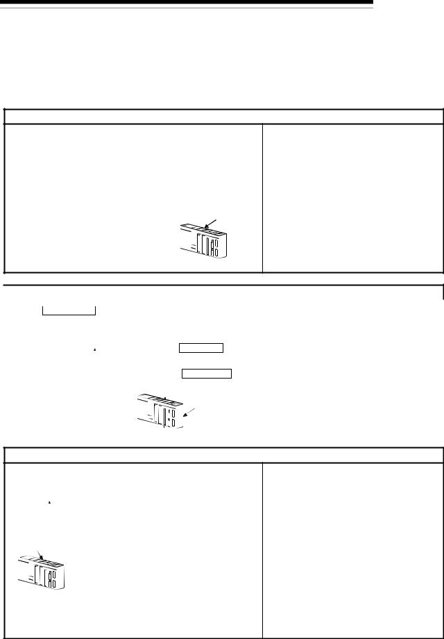
1 PRODUCT OUTLINE
1.1.2 Purpose and applications of positioning control
MELSEC-Q
"Positioning" refers to moving a moving body, such as a workpiece or tool (hereinafter, generically called "workpiece") at a designated speed, and accurately stopping it at the target position. The main application examples are shown below.
 Punch press (X, Y feed positioning)
Gear and ball screw |
|
|
320mm |
160mm |
15m/min |
||||||||
Y axis |
Y axis X axis |
(2000r/min) |
|||||||||||
|
|
|
|
|
|
|
|
|
|||||
servomotor |
|
Y axis |
|
|
|
|
|
|
|
|
|||
|
|
|
|
|
|
|
|
|
|
||||
|
|
|
|
Press |
15m/min |
||||||||
|
|
|
|
punching |
(1875r/min) |
||||||||
|
|
|
|
12 s |
|
||||||||
Press head |
|
X axis |
|
|
|
|
|
|
|
|
|||
|
|
|
|
|
|
|
|
|
|
|
|||
|
|
|
Gear and rack & pinion |
|
|||||||||
Servo |
|
X axis |
|
PLC |
|
||||||||
|
servomotor |
|
|
||||||||||
|
|
MELSEC-Q QD75 |
|||||||||||
amplifier |
|
|
|
||||||||||
Servo |
|
|
|
|
|
|
|
|
|
|
|
AD75 |
|
|
|
|
|
|
|
|
|
|
|
|
|
||
amplifier |
|
|
|
|
|
|
|
|
|
|
|
|
|
|
|
|
|
|
|
|
|
|
|
|
|||
|
|
|
X axis |
|
|
|
|
|
|
||||
|
|
|
|
|
|
|
|
|
|
|
|
|
|
Y axis
•To punch insulation material or leather, etc., as the same shape at a high yield, positioning is carried out with the X axis and Y axis servos.
•After positioning the table with the X axis servo, the press head is positioned with the Y axis servo, and is then punched with the press.
•When the material type or shape changes, the press head die is changed, and the positioning pattern is changed.

 Palletizer
Conveyor control |
|
|
|
|
|
|
|
|
|
|
• |
Using the servo for one axis, the palletizer is |
|
|
|
Conveyor |
|
|
|
|
|
positioned at a high accuracy. |
|||||
Servomotor |
|
|
|
|
|
|
|
|
|
|
• |
The amount to lower the palletizer according to |
|
(with brakes) |
|
|
|
|
|
|
|
|
|
|
|
the material thickness is saved. |
|
|
|
|
|
|
|
|
|
|
|
Position detector |
|
||
|
|
G |
|
|
|
|
|||||||
|
|
|
|
|
|
|
|
||||||
Servo amplifier |
Reduction |
|
|
Palletizer |
|
|
|||||||
gears |
|
|
|
|
|||||||||
|
|
Ball screw |
|
|
Unloader control |
|
|
||||||
|
|
(From QD75) |
|
|
|
|
|||||||
|
|
|
|
|
|
|
|
||||||
|
|
|
|
|
|
|
|
PLC |
|
|
|||
|
|
|
|
|
|
|
|
|
|||||
|
Teaching unit |
|
|
|
|
|
MELSEC-Q |
|
|
||||
|
AD75TU |
|
|
|
|
|
|
|
|
QD75 |
|
|
|
|
|
|
|
|
|
|
|
|
|
|
|
||
|
|
|
|
|
|
|
|
|
|
|
|
|
|
|
|
AD75 |
|
|
|
|
|
|
|
|
|
|
|
|
|
|
|
|
|
|
|
|
|||||
|
|
|
|
|
|
|
|
|
|
|
|
|
|
 Compact machining center (ATC magazine positioning)
Servomotor
|
|
|
|
|
|
|
Coupling |
Reduction |
|
|
|
|
|
|
|
|
|
|
gears |
|
|
|
|
|
|
|
|
|
|
ATC tool |
|
|
|
|
|
|
|
|
|
|
magazine |
|
|
Servo |
|
|
|
|
|
|
|
|||
amplifier |
|
|
|
Positioning |
|
|
|
|||
|
|
|
|
|
|
|
Tool |
|
|
|
QD75 |
|
|
|
pin |
|
|
||||
|
|
|
|
(12 pcs., 20 pcs.) |
|
|
||||
|
|
|
|
|
|
|
|
|
|
|
|
|
|
|
|
|
|
|
Rotation direction |
Rotation direction |
|
|
|
|
|
|
|
|
PLC |
for calling |
|
for calling |
|
|
|
|
|
|
|
11, 12, 1, 2 or 3 |
17 to 20, 1 to 5 |
||
|
|
|
|
|
|
|
MELSEC-Q |
Current |
Current |
|
|
|
|
|
|||||||
AD75 |
|
|
|
|
value |
|
value |
|||
|
|
|
|
|
|
|
|
retrieval |
retrieval |
|
|
|
|
|
|
|
|
|
position |
position |
|
|
|
|
|
|
|
|
|
Rotation direction |
Rotation direction |
|
|
|
|
|
|
|
|
|
for calling 5, 6, 7, 8, 9 or 10 |
for calling 7 to 16 |
|
|
|
|
|
|
|
|
|
<No. of tools: 12> |
<No. of tools: 20> |
|
•The ATC tool magazine for a compact machining center is positioned.
•The relation of the magazine's current value and target value is calculated, and positioning is carried out with forward run or reverse run to achieve the shortest access time.
1 - 5
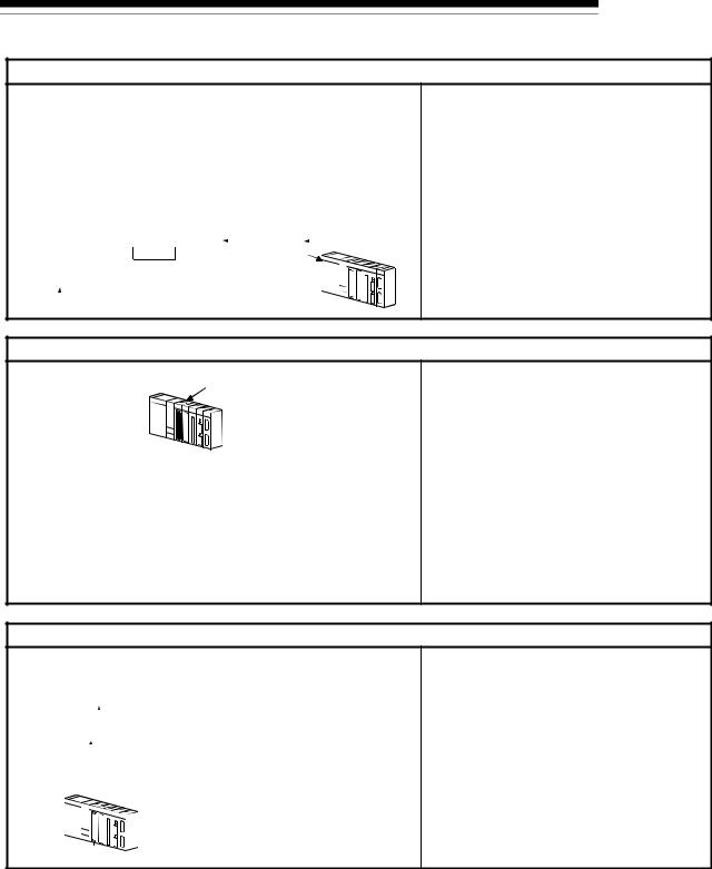
1 PRODUCT OUTLINE
MELSEC-Q
 Lifter (Storage of Braun tubes onto aging rack)
|
|
|
|
|
Unloader |
|||||||
|
|
|
|
|
Loader/unloader |
|||||||
B conveyor |
|
|
|
Aging rack |
||||||||
|
|
|
|
|||||||||
Lifter |
C |
|
|
|
|
|
|
|
|
|
||
Counter- |
conveyor |
|
|
|
|
|
|
|
|
|
||
A conveyor |
|
Servo amplifier |
||||||||||
weight |
|
|||||||||||
|
|
|
|
|
|
|
|
|
|
|
|
|
Reduction |
|
G2 |
|
|
|
|
|
|
|
|
||
|
|
|
|
|
|
|
|
|
|
|
|
|
|
|
|
|
|
|
|
|
|
|
|
|
|
gears |
Loader |
Positioning module |
||||||||||
G1 |
QD75 |
|
|
|
|
|
|
|
|
|||
Servomotor |
Servomotor |
|
|
|
|
|
|
|
|
|
||
|
|
|
|
|
|
|
|
|
|
|
|
|
(with brakes) |
|
|
|
|
|
|
|
|
|
|||
|
|
|
|
|
|
|
|
|
||||
|
Servo amplifier |
PLC MELSEC-Q |
||||||||||
•During the aging process of braun tubes, storage onto the rack is carried out by positioning with the AC servo.
•The up/down positioning of the lifter is carried out with the 1-axis servo, and the horizontal position of the aging rack is positioned with the 2-axis servo.
 Index table (High-accuracy indexing of angle)
AD75
PLC QD75
MELSEC-Q
Digital switch
Servo amplifier
•The index table is positioned at a high accuracy using the 1-axis servo.
Index table
|
Detector |
Worm gears |
Servomotor |
 Inner surface grinder
|
|
Servomotor |
Motor |
|
|
|
|||||||
|
|
|
|
|
|
|
|
|
|
Workpiece |
|
||
|
|
|
|
|
|
|
|
|
|
1M G |
|
||
|
Inverter |
|
|
|
|
|
|
|
Grinding stone |
|
|||
|
|
|
|
|
|
|
|
|
|
G Motor1M |
|
||
|
|
|
|
|
|
Servo |
|
|
Inverter |
|
|||
|
|
|
|
|
|
amplifier |
|
|
|||||
|
|
|
|
|
|
|
|
|
|||||
|
220VAC |
|
|
|
|
|
|
|
Fix the grinding |
|
|
||
|
|
|
|
|
|
|
|
stone, feed the |
|
|
|||
|
60Hz |
|
|
|
|
|
|
|
workpiece, and grind. |
|
|||
|
|
|
|
|
|
PLC |
|
|
|
|
|||
|
|
|
|
|
|
MELSEC-QOperation panel |
a. Total feed |
d. Rough grind- |
|||||
|
|
|
|
|
|
|
|
|
|
a |
d |
amount (mm) |
ing speed (mm/s) |
|
|
|
|
|
|
|
|
|
|
b |
e |
b. Finishing |
e. Fine grinding |
|
|
|
|
|
|
|
|
|
|
feed amount (mm) |
speed (mm/s) |
||
|
|
|
|
|
|
|
|
|
|
c |
|
c. Compensation |
|
|
QD75 |
|
|
|
|
|
|
|
|
|
amount (mm) |
|
|
|
|
|
|
|
|
|
|
|
|
|
|
||
|
|
|
|
|
|
|
|
|
|
|
|
|
|
•The grinding of the workpiece's inner surface is controlled with the servo and inverter.
•The rotation of the workpiece is controlled with the 1-axis inverter, and the rotation of the grinding stone is controlled with the 2-axis inverter. The workpiece is fed and ground with the 3-axis servo.
1 - 6
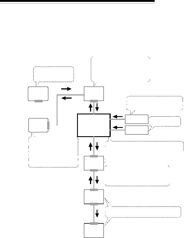
1 PRODUCT OUTLINE
1.1.3 Mechanism of positioning control
MELSEC-Q
Positioning control using the QD75 is carried out with "pulse signals". (The QD75 is a module that generates pulses). In the positioning system using the QD75, various software and devices are used for the following roles. The QD75 realizes complicated positioning control when it reads in various signals, parameters and data and is controlled with the PLC CPU.
Creates control order and conditions as a sequence program.
GX Developer 

Stores the created program.
The QD75 outputs the start signal and  stop signal following the stored program.
QD75 errors, etc., are detected.
PLC CPU
 Outputs signals such as the start
 signal, stop signal, limit signal and
 control changeover signal to the QD75.
GX Configurator  -QP
-QP
 Sets the parameters and
 positioning data for control.
 Outputs the start command for
 JOG operation, etc., during test
 operation with the test mode.
 Monitors the positioning operation.
|
|
|
|
|
|
External signal |
Issues commands by |
|
|
|
|
|
|
||
|
|
|
|
|
|
||
QD75 positioning |
|
|
|
|
transmitting pulses. |
||
module |
|
|
|
Manual pulse |
|
||
|
|
|
|||||
|
|
|
|
|
|
|
|
|
|
|
|
|
|
generator |
|
|
|
|
|
|
|
|
|
|
|
|
|
|
|
|
|
 Stores the parameter and data.
 Outputs pulses to the servo according to the
 instructions from the PLC CPU, GX Configurator-QP,
 external signals and manual pulse generator.
  Servo
Servo 


 amplifier


 Receives pulse commands from QD75, and
 drives the motor.
 Outputs the drive unit READY signal and
  zero signal to the QD75.
Motor
 Carries out the actual work according to commands
  from the servo.
Workpiece
1 - 7
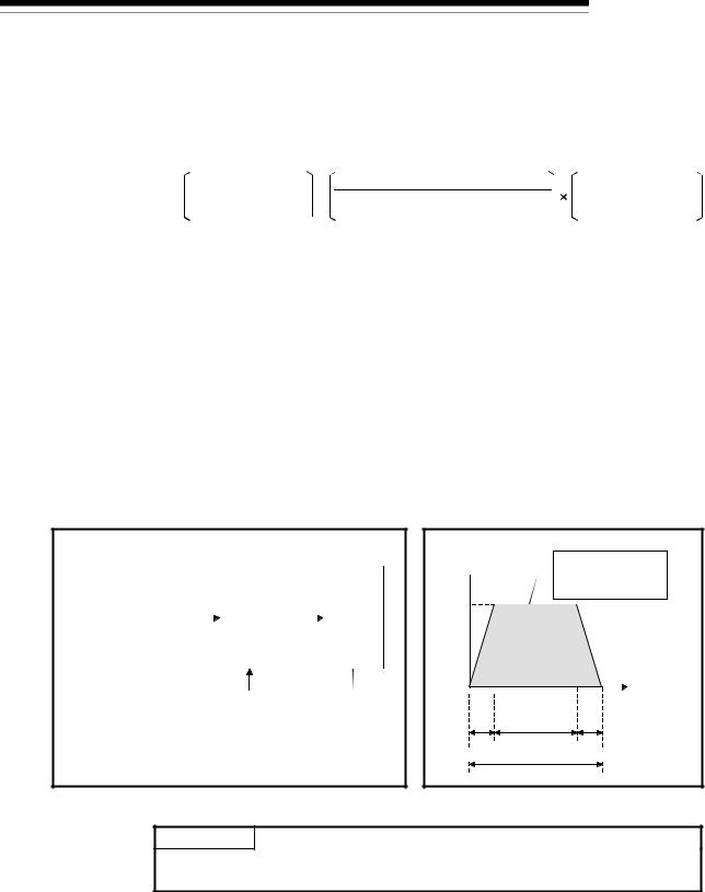
1 PRODUCT OUTLINE
MELSEC-Q
The principle of "position control" and "speed control" operation is shown below.
 Position control
The total No. of pulses required to move the designated distance is obtained in the following manner.
Total No. of pulses required to move designated distance
Designated distance
=Movement amount of machine (load) side when motor rotates once
No. of pulses required for motor to rotate once
 The No. of pulses required for the motor to rotate once is the "encoder resolution" described in the motor catalog specification list.
When this total No. of pulses is issued from the QD75 to the servo amplifier, control to move the designated distance can be executed.
The machine side movement amount when one pulse is issued to the servo amplifier is called the "movement amount per pulse". This value is the min. value for the workpiece to move, and is also the electrical positioning precision.
 Speed control
The "Total No. of pulses" mentioned above is invariably required for controlling the distance. For positioning or speed control, the speed must be controlled as well. The speed is determined by the frequency of pulses sent from the QD75 to the drive unit.
Positioning |
|
|
|
|
|
|
|
Servo |
|
|
Servo |
module |
|
|
|
|
|
|
|
amplifier |
motor |
||
|
|
|
|
|
|
|
|
|
|
|
|
|
|
|
|
|
|
|
|
|
|
|
Detector |
|
|
|
|
|
|
|
|
|
|
|
(Pulse |
|
|
|
|
|
|
|
|
|
|
|
encoder) |
Speed = Pulses frequency |
Feedback pulses |
||||||
Movement amount = No.of pulses |
|
|
|
|
|
|
|
Feedback pulses = |
|
|
|
|
|
|
|
|
|
|
|
|
|
|
|
Pulses generated by detector |
|
|
|
|
|
|
|
Pulse frequency
[pps] This area is the total  No. of commanded
pulses.
A
|
ta |
|
td (s) |
0.4 1.2 0.4
 Movement amount t = 2
Fig. 1.1 Relationship between position control and speed control
POINT
The QD75 controls the position with the "total No. of pulses", and the speed with the "pulse frequency".
1 - 8
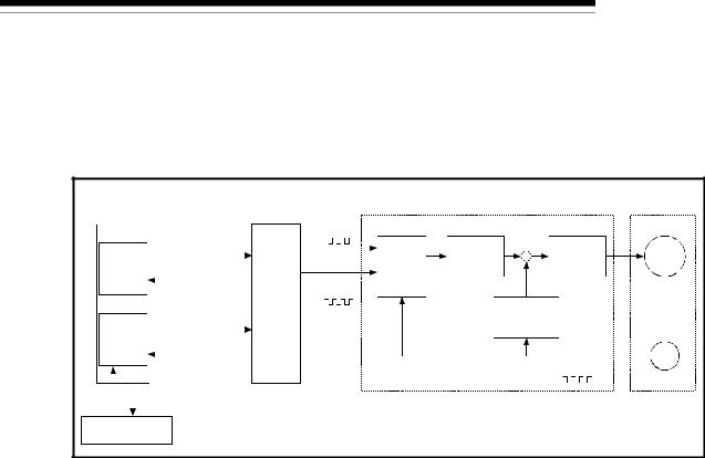
1 PRODUCT OUTLINE
1.1.4 Outline design of positioning system
MELSEC-Q
The outline of the positioning system operation and design, using the QD75, is shown below.
(1) Positioning system using QD75
PLC CPU |
Positioning module |
|
Drive unit |
|
Servomotor |
|||||
|
|
|
|
|
QD75 Forward run |
|
|
|
|
|
|
|
|
|
|
pulse train |
|
|
Speed |
|
|
|
|
|
|
|
|
Devia- |
D/A |
command |
Servo |
|
Program |
Read, write, etc. |
tion |
converter |
|
amplifier |
M |
||||
|
|
|||||||||
counter |
|
|
|
|
||||||
|
|
|
|
|
Reverse run |
|
|
|
|
|
|
|
|
|
|
|
|
|
|
||
|
|
|
|
|
Setting data pulse train |
|
|
|
|
|
Peripheral |
|
|
|
|
|
|
Interface |
|
|
|
|
|
|
|
|
|
|
|
|
||
devices |
Read, write, etc. |
|
|
|
|
|
||||
interface |
|
|
|
|
|
Feedback pulse |
PLG |
|||
|
|
|
|
|
||||||
|
Read, write, etc. |
|
|
|
||||||
|
|
|
|
|
|
|||||
|
|
|
|
|
|
|
||||
GX Configurator-QP |
|
|
|
|
|
|||||
Fig. 1.2 Outline of the operation of positioning system using QD75
(a)Positioning operation by the QD75
1)The QD75 output is a pulse train.
The pulse train output by the QD75 is counted by and stored in the deviation counter in the drive unit.
The D/A converter outputs an analog DC current proportionate to the count maintained by the deviation counter (called "pulse droop"). The analog DC current serves as the servomotor speed control signal.
2)The motor rotation is controlled by the speed control signal from the drive unit.
As the motor rotates, the pulse encoder (PLG) attached to the motor generates feedback pulses, the frequency of which is proportionate to the rotation speed.
The feedback pulses are fed back to the drive unit and decrements the pulse droop, the pulse count maintained by the deviation counter. The motor keeps on rotating as the pulse droop is maintained at a certain level.
3)When the QD75 terminates the output of a pulse train, the motor decelerates as the pulse droop decreases and stops when the count drops to zero.
Thus, the motor rotation speed is proportionate to the pulse frequency, while the overall motor rotation angle is proportionate to the total number of pulses output by the QD75.
Therefore, when a movement amount per pulse is given, the overall movement amount can be determined by the number of pulses in the pulse train.
The pulse frequency, on the other hand, determines the motor rotation speed (feed speed).
1 - 9
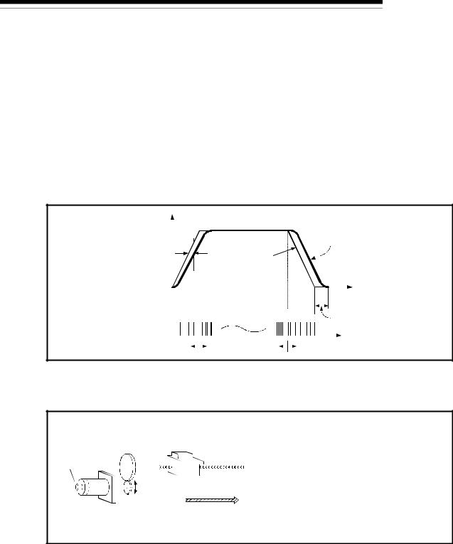
1PRODUCT OUTLINE
(b)Pulse train output from the QD75
MELSEC-Q
1)As shown in Fig. 1.3, the pulse frequency increases as the motor accelerates. The pulses are sparse when the motor starts and more frequent when the motor speed comes close to the target speed.
2)The pulse frequency stabilizes when the motor speed equals the target speed.
3)The QD75 decreases the pulse frequency (sparser pulses) to decelerate the motor before it finally stops the output.
There will be a little difference in timing between the decrease in the pulse frequency and the actual deceleration and stopping of the motor. This difference, called "the stop settling time", is required for gaining a stopping accuracy.
|
|
|
|
|
|
|
|
|
|
|
|
|
|
|
|
|
|
|
|
|
|
|
|
Servomotor |
||||||||
|
|
|
|
|
|
|
|
|
|
|
|
|
|
|
|
|
|
|
|
|
|
|
|
|||||||||
|
|
|
|
|
|
|
|
|
|
|
|
|
|
|
|
|
|
|
|
|
|
|
|
|||||||||
Speed V |
Pulse droop Pulse |
|
|
|
|
|
|
|
|
|
|
|
|
|
|
|
|
|
|
|
|
|
speed |
|||||||||
|
|
|
|
|
|
|
|
|
|
|
|
|
|
|
|
|
|
|
|
|
||||||||||||
|
|
|
|
|
|
|
|
|
|
|
|
|
|
|
|
|
|
|
|
|
||||||||||||
|
|
|
|
|
|
|
|
|
|
|
|
|
|
|
|
|
|
|
|
|
|
|
|
|
|
|
|
|
|
|||
|
|
|
|
|
|
|
|
|
|
|
|
|
|
|
|
|
|
|
|
|
|
|
|
|
|
|
|
|
|
|||
|
|
|
|
|
|
|
|
|
|
|
|
|
|
|
|
|
|
|
|
|
|
|
|
|
|
|
|
|
|
|||
|
|
|
|
|
|
|
|
|
|
|
|
|
|
|
|
|
|
|
|
|
|
|
|
|
|
|
|
|
|
|||
|
|
|
|
|
|
|
|
|
|
|
|
|
|
|
|
|
|
|
|
|
|
|
|
|
|
|
|
|
|
|||
|
|
|
|
|
|
|
|
|
|
|
|
|
|
|
|
|
|
|
|
|
|
|
|
|
|
|
|
|
|
|
||
|
amount |
distribution |
|
|
|
|
|
|
|
|
|
|
|
|
|
|
|
|
|
|
|
|
|
|
|
|
|
|
|
|
|
|
|
|
|
|
|
|
|
|
|
|
|
|
|
|
|
|
|
|
|
|
|
|
|
|
|
|
|
|
|
|
|
||
|
|
|
|
|
|
|
|
|
|
|
|
|
|
|
|
|
|
|
|
|
|
|
|
|
|
|
|
|
|
|
|
|
|
|
|
|
|
|
|
|
|
|
|
|
|
|
|
|
|
|
|
|
|
|
|
|
|
|
|
|
|
|
|
|
|
|
|
|
|
|
|
|
|
|
|
|
|
|
|
|
|
|
|
|
|
|
|
|
|
|
|
|
|
|||||
|
|
|
|
|
|
|
|
|
|
|
|
|
|
|
|
|
|
|
|
|
|
|
|
|
|
|
|
|||||
|
|
|
|
|
|
|
|
|
|
|
|
|
|
|
|
|
|
|
|
|
|
|
|
|
|
|
|
|||||
|
|
|
|
|
|
|
|
|
|
|
|
|
|
|
|
|
|
|
|
|
|
|
|
|
|
|
|
|||||
|
|
|
|
|
|
|
|
|
|
|
|
|
|
|
|
|
|
|
|
|
|
|
|
|
|
|
|
|||||
|
|
|
|
|
|
|
|
|
|
|
|
|
|
|
|
|
|
|
|
|
|
|
|
|
|
|
|
|||||
Accel- |
|
|
|
Decel- |
|
|
|
|
|
|
|
|
Time t |
|||||||||||||||||||
|
|
|
|
|
|
|
|
|
|
|
||||||||||||||||||||||
eration |
|
|
|
eration |
|
|
|
|
|
|
|
|
||||||||||||||||||||
|
|
|
|
|
|
|
|
|
|
|
|
|||||||||||||||||||||
|
|
|
|
|
|
|
|
|
|
|
|
|
|
|
|
|
|
|
|
|
|
|
|
|
|
|
|
|
|
|
|
Stop |
|
|
|
|
|
|
|
|
|
|
|
|
|
|
|
|
|
|
|
|
|
|
|
|
|
|
|
|
|
|
|
|
settling time |
Pulse train Rough |
Dense |
|
|
|
|
|
|
|
|
|
|
|
|
Rough |
||||||||||||||||||
Fig. 1.3 QD75 output pulses
(2) Movement amount and speed in a system using worm gears
|
|
|
|
|
|
|
|
V |
|
|
|
|
|
|
|
|
|||
Pulse encoder |
|
|
|
Workpiece |
|||||||||||||||
|
|
|
|
|
|
Worm gear |
|||||||||||||
(PLG) |
|
|
|
|
|
|
|
|
|
||||||||||
|
|
|
|
Table |
|
|
|
|
|
|
|
||||||||
|
|
|
|
|
|
|
|
|
|||||||||||
|
|
|
|
R |
|
|
|
|
|
|
|
|
|||||||
|
|
|
|
|
|
|
|
|
|
|
|
||||||||
|
|
|
|
|
|
|
L |
||||||||||||
|
|
|
|
|
|
|
|
|
|
|
|
|
|
|
|||||
Servomotor |
|
|
|
|
|
|
|
|
|
|
|
|
P |
||||||
|
|
|
|
|
|
|
|
|
P0 |
|
|
|
|
|
|
||||
|
|
|
|
|
|
|
|
|
|
|
|
|
|
|
|
||||
A : Movement amount per pulse (mm/pulse) Vs : Command pulse frequency (pulse/s)
n : Pulse encoder resolution (pulse/rev) L : Worm gear lead (mm/rev)
R : Deceleration ratio
V : Movable section speed (mm/s) N : Motor speed (r/min)
K : Position loop gain (1/s)
ε : Deviation counter droop pulse amount P0 : OP (pulse)
P : Address (pulse)
Fig. 1.4 System using worm gears
1 - 10
Loading...