


52" LCD Display Monitor
USER’S MANUAL BEDIENERHANDBUCH MANUAL DEL USUARIO MANUEL UTILISATEUR MANUALE UTENTE GEBRUIKERSHANDLEIDING

Index
Important Information................................................................................................................................... |
English-2 |
Safety Precautions, Maintenance & Recommended Use ........................................................................... |
English-4 |
Contents....................................................................................................................................................... |
English-5 |
Parts Name and Functions .......................................................................................................................... |
English-6 |
Buttons, Switch, and Indicator ....................................................................................................... |
English-6 |
Connectors and Terminals .............................................................................................................. |
English-7 |
Wireless Remote Control ............................................................................................................... |
English-8 |
< Operating Range for the Remote Control >........................................................................... |
English-9 |
< Handling the remote control > ............................................................................................... |
English-9 |
CAT5 Tx BOX.................................................................................................................................. |
English-9 |
Setup Procedure .......................................................................................................................................... |
English-10 |
CAT5 video connection................................................................................................................... |
English-12 |
How to Mount and Attach Options to the LCD Monitor............................................................................... |
English-14 |
Connections ................................................................................................................................................. |
English-15 |
Wiring Diagram ............................................................................................................................... |
English-15 |
Connecting a Personal Computer .................................................................................................. |
English-16 |
Connecting with Digital Interface Equipment ................................................................................ |
English-17 |
Connecting a DVD Player with component out/HDMI out/DVI out ................................................ |
English-18 |
Connecting to a VCR/Stereo Amplifier ........................................................................................... |
English-19 |
Basic Operation............................................................................................................................................ |
English-20 |
Power ON and OFF Modes ............................................................................................................ |
English-21 |
Power Indicator............................................................................................................................... |
English-21 |
Using Power Management ............................................................................................................ |
English-21 |
Selecting a video source ................................................................................................................ |
English-21 |
Picture Size .................................................................................................................................... |
English-21 |
Picture Mode .................................................................................................................................. |
English-21 |
Audio Source Switching ................................................................................................................. |
English-21 |
Information OSD ............................................................................................................................. |
English-22 |
OSD (On-Screen-Display) Controls.............................................................................................................. |
English-23 |
PICTURE......................................................................................................................................... |
English-24 |
SCREEN.......................................................................................................................................... |
English-26 |
AUDIO............................................................................................................................................. |
English-27 |
PICTURE IN PICTURE .................................................................................................................... |
English-27 |
CONFIGURATION 1........................................................................................................................ |
English-28 |
CONFIGURATION 2........................................................................................................................ |
English-29 |
ADVANCED OPTION ...................................................................................................................... |
English-30 |
NOTE .............................................................................................................................................. |
English-32 |
< IMAGE PERSISTENCE > ....................................................................................................... |
English-32 |
< For long life use of Public Display > ...................................................................................... |
English-32 |
< HOW TO SETUP SCHEDULE >............................................................................................. |
English-32 |
< PIP, POP and SIDE BY SIDE >............................................................................................... |
English-33 |
< Supplemental information of the auto brightness function > ................................................ |
English-33 |
< Remote control numbering function > ................................................................................... |
English-34 |
Controlling the LCD monitor via RS-232C/RS-485 Remote Control .......................................................... |
English-35 |
Features........................................................................................................................................................ |
English-37 |
Troubleshooting............................................................................................................................................ |
English-38 |
Specifications .............................................................................................................................................. |
English-40 |
Pin Assignment ............................................................................................................................................ |
English-41 |
English
English-1
Important Information
DECLARATION OF CONFORMITY
This device complies with Part 15 of FCC Rules. Operation is subject to the following two conditions. (1) This device may not cause harmful interference, and (2) this device must accept any interference received, including interference that may cause undesired operation.
U.S. Responsible Party: Mitsubishi Digital Electronics America, Inc.
Address: |
9351 Jeronimo Road, |
|
Irvine, California 92618 U.S.A. |
Tel. No.: |
+1 - (949) 465-6000 |
Type of Product: |
Computer Monitor |
Equipment Classification: Class B Peripheral |
|
Model: |
MDT521S (DT851) |
We hereby declare that the equipment specified above conforms to the technical standards as specified in the FCC Rules.
Windows is a registered trademark of Microsoft Corporation. All other brands and product names are trademarks or registered trademarks of their respective owners.
HDMI, the HDMI logo and High-Definition Multimedia Interface are trademarks or registered trademarks of HDMI Licensing LLC.
Canadian Department of Communications Compliance Statement
DOC: This Class B digital apparatus meets all requirements of the Canadian Interference-Causing Equipment Regulations.
C-UL: Bears the C-UL Mark and is in compliance with Canadian Safety Regulations according to CAN/CSA C22.2 No. 60950-1.
FCC Information
1.Use the attached specified cables with the MDT521S (DT851) color monitor so as not to interfere with radio and television reception.
(1)Please use the supplied power cord or equivalent to ensure FCC compliance.
(2)Please use the supplied shielded video signal cable, 15-pin mini D-SUB to 15-pin mini D-SUB.
2.This equipment has been tested and found to comply with the limits for a Class B digital device, pursuant to part 15 of the FCC Rules.
These limits are designed to provide reasonable protection against harmful interference in a residential installation. This equipment generates, uses, and can radiate radio frequency energy, and, if not installed and used in accordance with the instructions, may cause harmful interference to radio communications. However, there is no guarantee that interference will not occur in a particular installation. If this equipment does cause harmful interference to radio or television reception, which can be determined by turning the equipment off and on, the user is encouraged to try to correct the interference by one or more of the following measures:
• Reorient or relocate the receiving antenna.
• Increase the separation between the equipment and receiver.
• Connect the equipment into an outlet on a circuit different from that to which the receiver is connected.
• Consult your dealer or an experienced radio/TV technician for help.
If necessary, the user should contact the dealer or an experienced radio/television technician for additional suggestions. The user may find the following booklet, prepared by the Federal Communications Commission, helpful: “How to Identify and Resolve Radio-TV Interference Problems.” This booklet is available from the U.S. Government Printing Office, Washington, D.C., 20402, Stock No. 004-000-00345-4.
English-2
Important Information
WARNING
TO PREVENT FIRE OR SHOCK HAZARDS, DO NOT EXPOSE THIS UNIT TO RAIN OR MOISTURE. ALSO, DO NOT USE THIS UNIT’S POLARIZED PLUG WITH AN EXTENSION CORD RECEPTACLE OR OTHER OUTLETS UNLESS THE PRONGS CAN BE FULLY INSERTED.
REFRAIN FROM OPENING THE CABINET AS THERE ARE HIGH VOLTAGE COMPONENTS INSIDE.
REFER SERVICING TO QUALIFIED SERVICE PERSONNEL.
CAUTION
CAUTION |
TO REDUCE THE RISK OF ELECTRIC SHOCK, MAKE SURE POWER CORD IS UNPLUGGED FROM |
|
|
|
WALL SOCKET. TO FULLY DISENGAGE THE POWER TO THE UNIT, PLEASE DISCONNECT THE |
|
POWER CORD FROM THE AC OUTLET. DO NOT REMOVE COVER (OR BACK). NO USER |
|
SERVICEABLE PARTS INSIDE. REFER SERVICING TO QUALIFIED SERVICE PERSONNEL. |
|
This symbol warns user that uninsulated voltage within the unit may have sufficient magnitude to cause |
|
electric shock. Therefore, it is dangerous to make any kind of contact with any part inside this unit. |
|
This symbol alerts the user that important literature concerning the operation and maintenance of this unit |
|
has been included. Therefore, it should be read carefully in order to avoid any problems. |
CAUTION
This LCD Monitor uses a lamp that contains mercury. Disposal of the lamp or the LCD Monitor with the lamp may be regulated due to environmental considerations. For disposal or recycling information, please contact your local authorities or the Electronic Industries Alliance: www.eiae.org. (For US only).
Declaration
Declaration of the Manufacturer
We hereby certify that the color monitor MDT521S (DT851) is in compliance with
Council Directive 2006/95/EC:
– EN 60950-1 Council Directive 2004/108/EC:
–EN 55022
–EN 61000-3-2
–EN 61000-3-3
–EN 55024
and marked with
Mitsubishi Electric Corporation
2-7-3, Marunouchi,
Chiyoda-Ku
Tokyo 100-8310, Japan
Declaration of the Manufacturer
Note: This symbol mark is for EU countries only.
This symbol mark is according to the directive 2002/96/EC Article 10 Information for users and
Annex IV, and/or to the directive 2006/66/EC Article 20 Information for end-users and Annex II. Your MITSUBISHI ELECTRIC product is designed and manufactured with high quality
materials and components which can be recycled and/or reused.
This symbol means that electrical and electronic equipment, batteries and accumulators, at their end-of-life, should be disposed of separately from your household waste.
If a chemical symbol is printed beneath the symbol shown above, this chemical symbol means that the battery or accumulator contains a heavy metal at a certain concentration. This will be indicated as follows: Hg: mercury (0,0005%), Cd: cadmium (0,002%), Pb: lead (0,004%)
In the European Union there are separate collection systems for used electrical and electronic products, batteries and accumulators.
Please, dispose of this equipment, batteries and accumulators correctly at your local community waste collection/recycling centre.
Please, help us to conserve the environment we live in!
English-3
English

Safety Precautions, Maintenance & Recommended Use
FOR OPTIMUM PERFORMANCE, PLEASE NOTE THE FOLLOWING WHEN SETTING UP AND USING THE LCD COLOR MONITOR:
•DO NOT REMOVE MONITOR BACK COVER. There are no user serviceable parts inside and opening or removing covers may expose you to dangerous shock hazards or other risks.
Refer all servicing to qualified service personnel.
•Do not spill any liquids into the cabinet or use your monitor near water.
•Do not insert objects of any kind into the cabinet slots, as they may touch dangerous voltage points, which can be harmful or fatal or may cause electric shock, fire or equipment failure.
•Do not place any heavy objects on the power cord. Damage to the cord may cause shock or fire.
•Do not place this product on a sloping or unstable cart, stand or table, as the monitor may fall, causing serious damage to the monitor.
•When operating the LCD monitor with an AC 100-120V power supply in North America, use a power supply cord provided with this monitor.
•When operating the LCD monitor with an AC 220-240V power supply in Europe, use a power supply cord provided with this monitor.
•In UK, use a BS-approved power cord with molded plug having a black (10A) fuse installed for use with this monitor.
If a power cord is not supplied with this monitor, please contact your supplier.
•When operating the LCD monitor with a 220-240V AC power supply in Australia, use the power cord provided with this monitor.
If a power cord is not supplied with this monitor, please contact your supplier.
•For all othercase, use a power cord that matches the AC voltage of the power outlet and has been approved by and complies with the safety standard of your particular country.
•Do not place any objects onto the monitor and do not use the monitor outdoors.
•The inside of the fluorescent tube located within the LCD monitor contains mercury. Please follow the laws or rules of your municipality to dispose of the tube properly.
•Do not bend power cord.
•Do not use monitor in high temperature, humid, dusty, or oily areas.
•If monitor or glass is broken, do not come in contact with the liquid crystal and handle with care.
•Allow adequate ventilation around the monitor, so that heat can properly dissipate. Do not block ventilated openings or place the monitor near a radiator or other heat sources.
Do not put anything on top of the monitor.
•The power cable connector is the primary means of detaching the system from the power supply. The monitor should be installed close to a power outlet, which is easily accessible.
•Handle with care when transporting. Save packaging for transporting.
•Please clean the holes of back cabinet to reject dirt and dust at least once a year because of set reliability.
•If using the cooling fan continuously, it’s recommended to wipe holes a minimum of once a month.
•When installing the remote control batteries;
-Align the batteries according to the (+) and (-) indications inside the case.
-Align the (-) indication of the battery first inside the case.
CAUTION:
Immediately unplug your monitor from the wall outlet and refer servicing to qualified service personnel under the following conditions:
•When the power supply cord or plug is damaged.
•If liquid has been spilled, or objects have fallen into the monitor.
•If the monitor has been exposed to rain or water.
•If the monitor has been dropped or the cabinet damaged.
•If the monitor does not operate normally by following operating instructions.
Recommended Use
CAUTION:
•For optimum performance, allow 20 minutes for warm-up.
•Rest your eyes periodically by focusing on an object at least 5 feet away. Blink often.
•Position the monitor at a 90° angle to windows and other light sources to minimize glare and reflections.
•Clean the LCD monitor surface with a lint-free, nonabrasive cloth. Avoid using any cleaning solution or glass cleaner!
•Adjust the monitor’s brightness, contrast and sharpness controls to enhance readability.
•Avoid displaying fixed patterns on the monitor for long periods of time to avoid image persistence (after image effects).
•Get regular eye checkups.
Ergonomics
To realize the maximum ergonomic benefits, we recommend the following:
•Use the preset Size and Position controls with standard signals.
•Use the preset Color Setting.
•Use non-interlaced signals.
•Do not use primary color blue on a dark background, as it is difficult to see and may produce eye fatigue due to insufficient contrast.
English-4
Contents
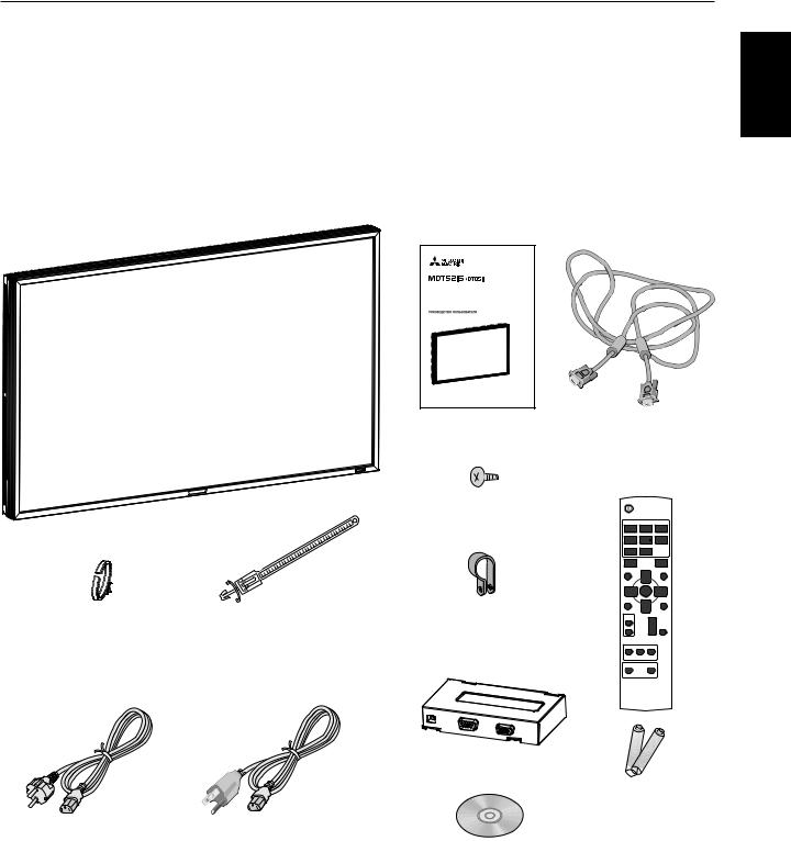
Your new MDT521S monitor box* should contain the following:
•LCD monitor
•Power Cord (3 m)
•Video Signal Cable (4 m)
•User’s Manual
•Wireless Remote Control and AAA Batteries
•Clamper x 2 (To prevent from falling)
•Clamper x 3 (For securing cables)
•Clamper x 2 (For securing the power cord and HDMI cable)
•Screw for Clamper (To prevent from falling) x 2
•CAT5 Tx BOX
•CD-ROM
52" LCD Display Monitor
USER’S MANUAL
BEDIENERHANDBUCH
MANUAL DEL USUARIO
MANUEL UTILISATEUR
MANUALE UTENTE
GEBRUIKERSHANDLEIDING
User’s Manual |
Video Signal Cable |
|
(D-SUB to D-SUB Cable) |
Screw for Clamper (M4) x 2
Clamper x 3 |
Clamper x 2 |
Clamper x 2 |
(For securing cables) |
(For securing the power cord |
(To prevent from falling) |
|
and HDMI cable) |
|
* The supplied power cord varies depending on destination.
CAT5 Tx BOX
For EU |
For North |
|
America |
|
Power cord |
CD-ROM
*For all other case, use a power cord that matches the AC voltage of the power outlet and has been approved by and complies with the safety standard of your particular country.
Wireless Remote Control
and AAA Batteries
* Remember to save your original box and packing material to transport or ship the monitor.
The following components are prepared as option.
•External Speakers
•Stand
English
English-5
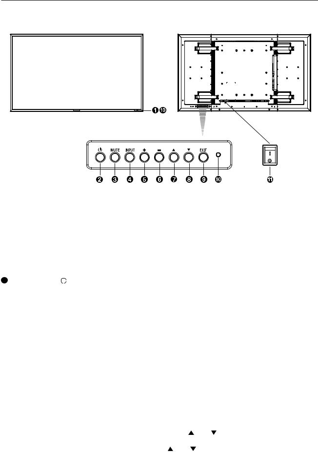
Parts Name and Functions
Buttons, Switch, and Indicator
ON
OFF
 Remote control sensor and Power indicator
Receives the signal from the remote control (when using the wireless remote control). See also page 9.
Glows green when the LCD monitor is in active and glows red when the LCD is in POWER OFF mode. When the LCD is in power save mode, it will glow both green and red. When SCHEDULE is enabled, it will blink green and glow red. See page 21. In the case of where a failure is detected, it will blink red.
 UP (
UP ( ) button
Activates the OSD menu when the OSD menu is turned-off. Acts as button to move the highlighted area up to select the adjustment with OSD menu.
 DOWN (
 ) button
Activates the OSD menu when the OSD menu is turned-off. Acts as button to move the highlighted area down to select the adjustment with OSD menu.
 POWER button (
  )
)
Switches the power on/off. See also page 20.
 MUTE button
Switches the audio mute ON/OFF.
 INPUT button
Acts as SET button with OSD menu.
(Toggle switches between [RGB1], [RGB2], [RGB3], [RGB4], [RGB5], [DVD/HD], [VIDEO<S>] and [VIDEO] .)
 PLUS (+) button
Acts as (+) button to increase the adjustment with OSD menu. Increase the audio output level when the OSD menu is turned off.
 MINUS (-) button
Acts as (-) button to decrease the adjustment with OSD menu. Decreases the audio output level when the OSD menu is turned off.
 EXIT button
Activates the OSD menu when the OSD menu is turned-off. Acts as EXIT button to move to previous menu with OSD menu.
 Brightness sensor (front, rear)
Sensor for the auto brightness function.
This function controls the screen brightness depending on the ambient light for easy viewing.
In addition, it changes the screen brightness depending on the ambient light and what are displayed on the screen to reduce power consumption as low as possible. See page 25, 33.
 Main Power Switch
On/Off Switch to turn main power on/off.
NOTE: Control Key Lock Mode
This control completely locks out access to all Control Key functions. To activate the control key lock function, press both of “ ” and “ ” and hold down simultaneously for more than 3 seconds. To resume back to user mode, press both of “ ” and “ ” and hold simultaneously for three (3) seconds.
English-6
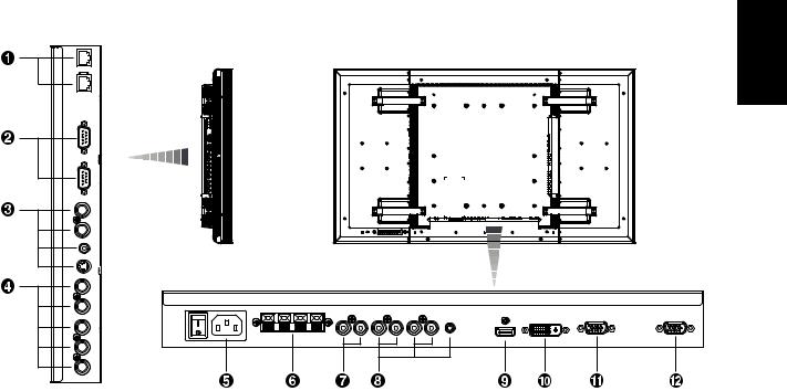
Connectors and Terminals
(OUT)
(IN)
(OUT)
 (IN)
(IN)
(OUT)
(IN)
 (IN)
(IN)
 (IN)
(IN)
English
 CAT5 input/output connectors (modular connector 8 pin)
The IN (RGB5 IN) connector is for connecting the CAT5 Tx BOX or the CAT5 OUT connector of a multi-connected MDT521S.
The OUT connector is for connecting the CAT5 (RGB5) IN connector of a multi-connected MDT521S.
 EXTERNAL CONTROL (mini D-Sub 9 pin)
Connect the IN connector with the RS-232C OUT connector of the computer or a multi-connected MDT521S monitor. Connect the OUT connector with the RS-232C IN connector of a multi-connected MDT521S monitor.
 VIDEO IN/OUT
VIDEO IN connector (BNC and RCA): To input a composite video signal. BNC and RCA are not available at the same time. (Use only one input).
VIDEO OUT connector (BNC): To output the composite video signal from VIDEO IN connector.
S-VIDEO IN connector (MINI DIN 4 pin): To input the S-video (Y/C separate signal).
 RGB 4 / DVD/HD IN (BNC)
To input the analog RGB signals from a computer or other RGB equipment.
Connecting equipment such as a DVD player, HDTV device, or Laser disc player. See page 16, 18.
 AC IN connector
Connects with the supplied power cord.
 EXTERNAL SPEAKER TERMINAL
To output the audio signal for external speakers from AUDIO 1, 2, 3 jack or HDMI.
 AUDIO OUT
To output the audio signal from the AUDIO IN 1, 2, 3 jack or HDMI.
 AUDIO IN 1, 2, 3
To input the audio signal from external equipment such as a computer, VCR or DVD player.
 RGB 1 IN (HDMI)
To input the digital RGB signals from a computer.
*This connector does not support analog input. AUDIO is supported via HDMI.
 RGB 2 IN (DVI-D)
To input the digital RGB signals from a computer.
*This connector does not support analog input. AUDIO is supported via DVI-D.
 RGB 3 IN (mini D-Sub 15 pin)
To input the analog RGB signals from a computer or other RGB equipment.
 RGB OUT (mini D-Sub 15 pin)
To output the signal from RGB 3, 4 or 5 IN.
English-7
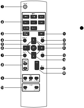
Wireless Remote Control
 POWER button
Switches the power on/off.
*If LED Power Indicator on the monitor is not glowing, then no controls will work.
 INPUT button
Selects from input signal, [RGB1] (HDMI), [RGB2] (DVI-D), [RGB3] (D-SUB), [RGB4] (BNC), [RGB5] (CAT5), [DVD/HD] (YPbPr), [VIDEO<S>] and [VIDEO].
 PICTURE MODE button
Selects from picture mode, [HIGHBRIGHT], [STANDARD], [sRGB], [CINEMA]. See page 21.
HIGHBRIGHT: for moving image such as Video STANDARD: for images (Factory setting) sRGB: for text based images
CINEMA: for movies.
 DISPLAY button
To switch the information OSD on/off. See page 22.
 SET button
Acts as SET button with OSD menu.
 MINUS button decrease
Acts as (-) button to decrease the adjustment with OSD menu. Small screen which adjusted “PIP” mode moves left.
 AUTO SETUP button
To enter the auto setup menu. See page 28.
 AUDIO INPUT button
Press to change the audio source for each video source. The audio source is changed from [AUDIO1] to [AUDIO2], [AUDIO3] and [HDMI] in order. Note that you cannot select the audio source for [VIDEO<S>] or [VIDEO]. [HDMI] is selectable only when the video source is [RGB 1] and [RGB 2].
 PIP (Picture In Picture) button
ON/OFF button: PIP-ON/OFF. See page 27.
INPUT button: Select the “picture in picture” input signal. CHANGE button: Replaces to the main picture and sub picture.
Note:
The “PIP” and “POP” modes do not function when the screen size is “CUSTOM” or “REAL”.
 STILL button
ON/OFF button: To switch the still picture mode on/off. CAPTURE button: Updates the still picture.
 SIZE button
Selects picture size, [FULL], [NORMAL], [CUSTOM] , [DYNAMIC] and [REAL]. See page 21.
 MENU button
To switch the menu mode on/off.
 UP button
Acts as button to move the highlighted area up to select the adjustment with OSD menu.
Small screen which adjusted “PIP” mode moves up.
 PLUS button increase
Acts as (+) button to increase the adjustment with OSD menu. Small screen which adjusted “PIP” mode moves right.
 EXIT button
Turn to previous menu with OSD menu.
 DOWN button
Acts as button to move the highlighted area down to select the adjustment with OSD menu.
Small screen which adjusted “PIP” mode moves down.
 MUTE button
To switch the mute function on/off.
 VOLUME button
Increases or decreases the audio output level.
English-8
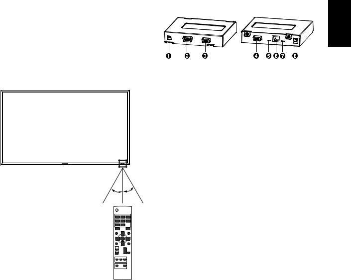
< Operating Range for the Remote Control >
Point the top of the remote control toward the LCD monitor's remote sensor during button operation.
Use the remote control within a distance of about 7 m/23 ft. from the front of the LCD monitor's remote control sensor and at a horizontal and vertical angle of within 30° within a distance of about 3 m/10 ft.
30° 30°
CAUTION:
Important, the remote control system may not function when direct sunlight or strong illumination strikes the remote control sensor of the LCD monitor, or when there is an object in the path.
< Handling the remote control >
*Do not subject to strong shock.
*Do not allow water or other liquid to splash the remote control. If the remote control gets wet, wipe it dry immediately.
*Avoid exposure to heat and steam.
*Other than to install the batteries, do not open the remote.
CAT5 Tx BOX
 USB (B type)
Connected to the USB connector (A type) of the computer.
CAUTION:
We have checked the operation of the USB connector by connecting it with our computers according to the USB standards.
When the CAT TX5 BOX is combined with your computer system or USB hub system, check in advance that it operates properly.
 EXTERNAL CONTROL IN (mini D-Sub 9 pin)
Connected to the RS-232C OUT connector of the computer.
Note:
RS-232C connection isn’t necessary when the COM port number set by the USB driver is used. Make selection using the input select switch (USB/RS-232C), as necessary.
 RGB IN (mini D-Sub 15 pin)
To input the analog RGB signals from other monitor.
 RGB OUT (mini D-Sub 15 pin)
To output the analog RGB signals from a computer.
 Input select switch (USB/RS-232C)
Switches the control input between the USB connector and the RS-232C connector.
 CAT5 OUT (modular connector 8 pin)
Connected to the CAT5 (RGB5) IN connector of MDT521S.
 Composite sync signal level switch
Switches the composite sync signal level. The TTL level and the 0.3V level are switched.
 Auxiliary power supply input connector (DC IN 5 V)
Though the power is supplied from the above-mentioned USB connector, an auxiliary DC power adopter (commercially available) is also available. Power can be drawn from the USB connector and the auxiliary power supply at the same time.
CAUTION:
The auxiliary power supply input connector isn’t intended for general use. Commercial DC power connectors are available in different shapes. When you want to use this connector, consult a qualified electrician in advance.
English
English-9
Setup Procedure
1. Determine the installation location
CAUTION:
DO NOT ATTEMPT TO INSTALL THE LCD MONITOR BY YOURSELF.
Installing your LCD display must be done by a qualified technician. Contact your dealer for more information.
CAUTION:
MOVING OR INSTALLING THE LCD MONITOR MUST BE DONE BY TWO OR MORE PEOPLE.
Failure to follow this caution may result in injury if the LCD monitor falls.
CAUTION:
Do not mount or operate the display upside down, face up, or face down.
CAUTION:
Do not install the LCD monitor where it will be exposed to direct sunlight, as this will result in display defects.
CAUTION:
This LCD has a temperature sensor and cooling fan. If the LCD becomes too hot, the cooling fan will turn on automatically. If the LCD becomes overheated and the cooling fan is running, the “Caution” menu will appear. If the “Caution” menu appears, discontinue use and allow the unit to cool.
When the LCD monitor is used in an enclosure or with protection on LCD surface, please check the inside temperature of monitor by “HEAT STATUS” (See page 31). The temperature is too hot than normal condition, please set “cooling fan” to ON on SCREEN SAVER function (See page 28).
IMPORTANT:
Lay the protective sheet, which was wrapped around the LCD monitor when it was packaged, beneath the LCD monitor so as not to scratch the panel.
2. Installing and removing the remote control batteries
The remote control is powered by 1.5V AAA batteries. To install or replace batteries:
How to install the batteries
1.Unlock and pull up the cover in the arrow’s direction.
2.Align the batteries according to the (+) and (–) indications inside the case.
3.Replace the cover.
How to remove the batteries
1.Unlock and pull up the cover in the arrow’s direction.
2.Remove the batteries.
CAUTION:
Incorrect use of batteries can result in leaks or bursting. Be careful especially about the following points.
•Place “AAA” batteries matching the + and - signs on each battery to the + and - signs of the battery compartment.
•Do not mix battery types.
•Do not combine new batteries with used ones. It causes shorter battery life or leakage of batteries.
•Remove dead batteries immediately to prevent battery liquid from leaking into the battery compartment. Don't touch exposed battery acid, it cause damage to your skin.
NOTE:
If you do not intend to use the Remote Control for a long period, remove the batteries.
3. Connect external equipment (See page 15-18)
•To protect the connected equipment, turn off the main power before making connections.
•Refer to your equipment user manual.
4. Connect the supplied power cord
•The power outlet socket should be installed as near to the equipment as possible, and should be easily
accessible.
•Fully insert the prongs into the power outlet socket. Loose connection may cause noise.
NOTE:
Please refer to “Safety Precautions, Maintenance & Recommended Use” section of this manual for proper selection of AC power cord.
Clamper
Use the clamper |
to secure the |
cable firmly. |
5. Switch on the power of all the attached external equipment
When connected with a computer, switch on the power of the computer first.
English-10

6. Operate the attached external equipment
Display the signal on the external equipment you wish.
7. Adjust the sound
Make adjustments lowering or rising the volume as required.
8. Adjust the screen (See pages 24-34)
Make adjustments to the display position or settings if required.
9. Adjust the image (See page 24-34)
Make adjustments to brightness or contrast if required.
10. Recommended Adjustment
To reduce the risk of “image persistence”, please adjust the following items based on the application being used. “POWER SAVE” (See page 28), “SCREEN SAVER” (See page 28), “SIDE BORDER COLOR”(See page 28), “DATE AND TIME” (See page 31), “SCHEDULE”(See page 31).
11. Installing and removing the stands
The stands are prepared as option.
Refer to the user’s manual of the stand for more information.
Stands
(Longer portion comes to the front.)
Screws
How to install the stands
1.Please turn monitor off.
2.Fasten screws on both sides of the monitor.
NOTE:
Install the stands so that their longer portions come to the front.
How to remove the stands
1.Spread the protective sheet on the flat surface, such as a desk.
2.Place monitor on the protective sheet.
3.Remove screws with a screwdriver and place them in a safe place for reuse.
12. Connecting HDMI cable
Clamper
Use the clamper to secure the cable firmly.
English
English-11
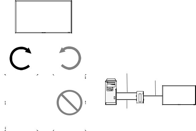
13. When MDT521S is installed in portrait position
Conditions
MDT521S can be installed in portrait position, under the following conditions:
Caution:
Portrait position is effective only when wall-mounted or ceiling-mounted.
The stands(legs) can not be fitted to the monitor in portrait position.
Placing the monitor in portrait position, will shorten the average life of the LCD backlight.
Operational Environment (Temperature) shall be limited, as shown below:
Operational Environment:
Temperature |
5 - 35 °C / 41 - 95 °F |
Humidity |
20 - 80 % (without condensation) |
Please orientate the monitor in the direction shown below: Do not place monitor in landscape in any other manner. Optional speakers (SP-521S) can not be attached when this LCD monitor is installed in portrait position.
How to set-up
The “


 ” logo should be on the LEFT side when facing the monitor.
Landscape
Clockwise |
Counterclockwise |
90° |
90° |
|
|
|
MDT521S |
|
MDT521S |
|
||
|
|
|
|
|
|
|
|
|
|
|
|
CAT5 video connection
The CAT5 video connection function is for transmitting the analog RGB video signal of the computer and the control signal of the monitor over a long distance using CAT5 cables. The computer can control the monitor via the supplied CAT5 Tx BOX.
Caution:
Never connect network devices (such as a hub and a computer for LAN) to the CAT5 Tx BOX and the IN and OUT connectors of the monitor. If they are connected, the network devices themselves, CAT5 Tx BOX, and monitor may be damaged.
1. Installation of the USB driver for CAT5 serial communication control
To connect the computer and the CAT5 Tx BOX via USB interface, it is necessary to install the USB driver to the computer from the CD-ROM supplied with the monitor.
(When connecting the computer and the CAT5 Tx BOX via RS-232C interface, you don’t have to install the USB driver.)
OS supported: Windows XP, Windows Vista®
How to install:
1) Installation to Windows XP
Start the “PL2303-Driver_XP2K_v******.exe” file in the Windows XP folder on the CD-ROM supplied with the monitor
and install the driver according to the instructions displayed on the screen.
2) Installation to Windows Vista®
Start the “PL2303_Prolific_Vista_******.exe” file in the Windows VISTA folder on the CD-ROM supplied with the
monitor and install the driver according to the instructions displayed on the screen.
2. Connection of the CAT5 video connection function
There are two cases of connection.
1) Connection to one monitor
USB cable
Computer
CAT5 cable
CAT5 Tx BOX (supplied)
Monitor
VGA (mini D-SUB 15-pin) cable (supplied)
1.Connect the USB connector of the supplied CAT5 Tx BOX and that of the computer using a commercially available USB cable. (When the USB driver isn’t available, connect an RS-232C cable in addition to the USB cable. In this case, the RS-232C cable serves for supplying the power to the CAT5 Tx BOX.) See page 35.
English-12
2.Connect the D-SUB input connector of the CAT5 Tx BOX and the VGA (D-SUB) output connector of the computer using the signal cable (mini D-SUB 15-pin cable) supplied with the monitor.
3.Connect the modular connector of the CAT5 Tx BOX and the CAT5 (RGB5) IN connector of the monitor using a commercially available CAT5 cable.
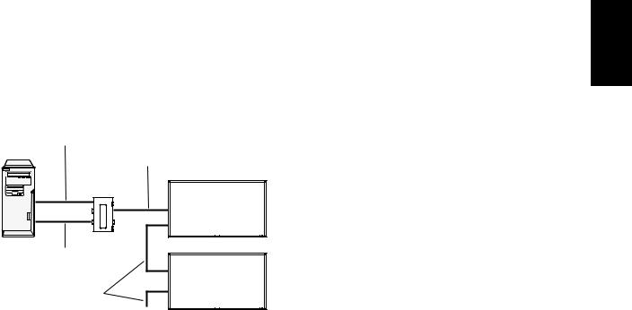
2) Connection to multiple monitors
USB cable
Computer
CAT5 cable
CAT5 Tx BOX (supplied)
Monitor
VGA (mini D-SUB 15-pin) cable (supplied)
Monitor
CAT5 cable
…
1.In addition to the connection made step 1) above, connect the CAT5 OUT connector of the first monitor and the CAT5 (RGB5) IN connector of the second monitor using a commercially available CAT5 cable.
2.Connect the third and later monitors in the same way. You can connect up to 5 monitors.
Allowable cable length
Connection |
Max. cable length/signal timing |
|
|
One monitor |
150 m / 1920 x 1080 @60 Hz |
|
|
Multiple moni- |
200 m / 1920 x 1080 @60 Hz |
tors |
(Total length of the connected cables) |
|
|
The lengths given above are based on the actual measurements using our standard signal source and the recommended cable as follows. Before installation, check the monitor operation in advance by connecting it with your computer and cables.
Recommended cable:
8-pin modular connector, straight-through, shielded, Category 5 or 5e
3. Various settings involved in the CAT5 video connection
In the case of the CAT5 video connection, configure the following settings displayed on the OSD screen. (See page 29.)
1) CAT5 CABLE LENGTH
Select the cable length, and the defaults of all the adjustment values are automatically determined.
Select the length that is closest to the actual length of your cable.
2) CAT5 EQ
Make adjustment so that blur and smear of the displayed letters and graphic objects are minimized.
3) CAT5 R-GAIN/G-GAIN/B-GAIN
When the displayed image is dark, increase each value. When whites aren’t displayed as intended, adjust the R-GAIN and B-GAIN values.
4) CAT5 R-SKEW/G-SKEW/B-SKEW
Adjust each value so that the color deviation in the displayed letters and graphic objects is minimized.
English
English-13
 Loading...