


HARDWARE MANUAL
F940GOT-SWD-E/LWD-E

F940GOT-SWD-E/LWD-E
Foreword
•This manual contains text, diagrams and explanations which will guide the reader in the correct installation and operation of the communication facilities of FX series.
•Before attempting to install or use the communication facilities of FX series this manual should be read and understood.
•If in doubt at any stage of the installation of the communication facilities of FX series always consult a professional electrical engineer who is qualified and trained to the local and national standards which apply to the installation site.

F940GOT-SWD-E/LWD-E
F940GOT-SWD-E/LWD-E
HARDWARE MANUAL
Manual number : JY992D77901 Manual revision : D
Date |
: February 2000 |
i

F940GOT-SWD-E/LWD-E
Guidelines for the safety of the user and protection of the F940GOT-SWD-E/LWD-E
This manual provides information for the installation and use of the Graphic Operation Terminal F940GOT. The manual has been written to be used by trained and competent personnel. The definition of such a person or persons is as follows;
a ) |
Any engineer who is responsible for the planning, design and construction of automatic equipment |
|
using the product associated with this manual should be of a competent nature, (trained and qualified |
|
to the local and national standards required to fulfill that role). These engineers should be fully aware |
|
of safety with regards to automated equipment. |
b ) |
Any commissioning or service engineer must be of a competent nature, trained and qualified to the |
|
local and national standards required to fulfill that job. These engineers should also be trained in the |
|
use and maintenance of the completed product. This includes being completely familiar with all asso- |
|
ciated documentation for the said product. All maintenance should be carried out in accordance with |
|
established safety practices. |
c ) |
All operators of the compliance product should be trained to use that product in a safe and coordi- |
|
nated manner in compliance to established safety practices. The operators should also be familiar |
|
with all documentation which is connected with the actual operation of the completed equipment. |
Note: The term ‘completed equipment’ refers to a third party constructed device which contains or uses the product associated with this manual.
ii

F940GOT-SWD-E/LWD-E
Note’s on the symbology used in this manual
At various times through out this manual certain symbols will be used to highlight points of information which are intended to ensure the users personal safety and protect the integrity of the equipment. Whenever any of the following symbols are encountered, its associated note must be read and understood. Each of the symbols used will now be listed with a brief description of its meaning.
Hardware warnings
1 ) Indicates that the identified danger WILL cause physical and property damage.
2 ) Indicates that the identified danger POSSIBLY cause physical and property damage.
3 ) Indicates a point of further interest or further explanation.
Software warnings
1 ) Indicates special care must be taken when using this element of software.
2 ) Indicates a special point of which the user of the associate software element should be aware.
3 ) Indicates a point of interest or further explanation.
iii

F940GOT-SWD-E/LWD-E
Memo
iv

F940GOT-SWD-E/LWD-E
CONTENTS |
|
|
1. INTRODUCTION................................................................................... |
1-1 |
|
1.1 |
Outline of product ................................................................................................ |
1-2 |
1.2 |
Product configuration........................................................................................... |
1-8 |
1.3 |
System configuration ......................................................................................... |
1-14 |
2. Installation, Wiring and General Specifications |
.....................................2-1 |
|
2.1 |
Installation of main body...................................................................................... |
2-1 |
2.2 |
Wiring of power supply ........................................................................................ |
2-4 |
2.3 |
Functions of operation keys and connectors ....................................................... |
2-9 |
2.4 |
Outside dimensions ........................................................................................... |
2-12 |
2.5 |
General specificationsl ...................................................................................... |
2-13 |
2.6 |
Connection to personal computer...................................................................... |
2-15 |
2.7 |
CPU port connection ......................................................................................... |
2-18 |
2.8 |
Computer link port connection (MELSEC A Series) .......................................... |
2-26 |
2.9 |
Connection to SYSMAC C Series ..................................................................... |
2-29 |
2.10 |
Connection to FLEX-PC N Series ..................................................................... |
2-32 |
2.11 |
Connection by general-purpose communication ............................................... |
2-35 |
3. |
Startup................................................................................................... |
3-1 |
|
3.1 |
Startup procedure................................................................................................ |
3-2 |
|
3.2 |
Operation environment setting ............................................................................ |
3-5 |
|
4. |
Extension Module.................................................................................. |
4-1 |
|
4.1 |
Data transfer adaptor........................................................................................... |
4-1 |
|
v

F940GOT-SWD-E/LWD-E
5. Maintenance.......................................................................................... |
5-1 |
|
5.1 |
Outline of maintenance........................................................................................ |
5-1 |
5.2 |
Replacement of battery ....................................................................................... |
5-3 |
5.3 |
Replacement of backlight .................................................................................... |
5-5 |
6. Troubleshooting..................................................................................... |
6-1 |
|
6.1 |
Power indication .................................................................................................. |
6-1 |
7. Additional Functions (in Ver3.00 or later) .............................................. |
7-1 |
|
7.1 |
Applicable Versions and Models ......................................................................... |
7-1 |
7.2 |
Connection to MELSEC QnA Series PC ............................................................. |
7-2 |
7.3 |
Connection to SLC 500 Series ............................................................................ |
7-3 |
7.4 |
Connection to Bar Code Reader ......................................................................... |
7-5 |
7.5 |
Screen Hard Copy Function ................................................................................ |
7-7 |
7.6 |
Additional Function in Alarm History Display....................................................... |
7-8 |
7.7 |
Specification of Ten-Key Window Initial Display Position .................................... |
7-8 |
8. Additional Functions (in V3.10 or later) ................................................. |
8-1 |
|
8.1 |
Applicable Versions and Models ......................................................................... |
8-1 |
9. Additional Functions (in V4.00 or later) ................................................. |
9-1 |
|
9.1 |
Applicable Versions and Models ......................................................................... |
9-1 |
Note to User
This manual describes installation, wiring and the specifications of the F940GOT. For handling and operating procedures of the F940GOT main body, refer to the
F940GOT Operation Manual offered separately.
vi

F940GOT-SWD-E/LWD-E |
INTRODUCTION 1. |
1.INTRODUCTION
This section describes the product configuration and the system configuration of the graphic operation terminal.
Confirm various functions of each unit.
1-1

F940GOT-SWD-E/LWD-E |
INTRODUCTION 1. |
1.1Outline of product
The graphic operation terminal (which may be hereafter abbreviated as "GOT") is attached on the panel face of a control panel or an operation panel, and connected to a program connector in an FX or A Series programmable controller (which may be hereafter abbreviated as "PLC") (except the A0J2) inside the control panel.
Not only the CPU port connection method but also the computer link port connection method is available so that the GOT can be connected to a PLC other than MELSEC or a micro computer board.
You can monitor various devices and change the data of the PLC while checking the screen of the GOT.
There are several display screens built in the GOT which offer various functions. In addition, you can create display screens.
The built-in screens (system screens) and the screens made by the user (user screens) have the following functions respectively.
FX or
A Series PLC
Program connector
GOT main body
1-2
F940GOT-SWD-E/LWD-E |
INTRODUCTION 1. |
User screens
1)Screen display function
The screens created by the user can be displayed. The following functions can be assigned to each screen. And the screens to be displayed can be limited using the security function.
a)Display function
-Up to 500 screens created by the user can be displayed. The screens can be created using the FX-PCS-DU/WIN-E V2.00 for the DU or using the SWoD5C-GOTRE-PACK ("o" indicates a numeric not less than 1.) for the GOT. Two or more screens can be overlaid or changed over.
-Not only characters such as alphabets, numerics, Hiragana, Katakana and Kanji but also simple graphics such as straight lines, circles and rectangles can be displayed. In the F940GOT-SWD-E, screens can be displayed in 8 colors.
b)Monitor function
-Set values and current values of word devices in the PLC can be displayed in numerics or bar graphs for monitoring.
-The specified range of the screen can be displayed reversely in accordance with the ON/OFF status of bit devices in the PLC.
1-3

F940GOT-SWD-E/LWD-E |
INTRODUCTION 1. |
c)Data change function
-The numeric data being monitored can be changed.
d)Switch function
-By manipulating the operation keys in the GOT, bit devices in the PLC can be set to ON and OFF. The display panel face can be assigned as touch keys to offer the switch function.
Make sure to press a touch key by fingers.
If a touch key is pressed by a hard or sharp object, it may become failed.
1-4

F940GOT-SWD-E/LWD-E |
INTRODUCTION 1. |
System screens
1)Monitor function
a)List program (only in the FX Series)
- Programs can be read, written and monitored in the form of instruction list program.
b)Buffer memory (only in the FX2N and FX2NC Series)
-The contents of buffer memories (BFMs) of special blocks can be read, written and monitored.
c)Device monitor
-The ON/OFF status of each device and the set value and the current value of each timer, counter and data register in the PLC can be monitored and changed.
-Specified bit devices can be forcedly set to ON and OFF.
Different from the monitor function in the screen display function described in the previous page, the screen can be displayed only inputting a desired device No. from the keyboard.
1-5

F940GOT-SWD-E/LWD-E |
INTRODUCTION 1. |
d)Data sampling function
The current value of specified data registers are acquired in a constant cycle or when the trigger condition is satisfied.
-The sampling data can be displayed in the form of list or graph. -The sampling data can be output to a printer in the form of list.
e)Alarm function
Alarm messages can be assigned to up to 256 consecutive bit devices in the PLC. When a bit device becomes ON, the assigned message is displayed (overlapped) on the user screen.
In addition, a specified user screen can be displayed by setting a corresponding bit device to ON.
-When a bit device becomes ON, a corresponding message is displayed on the user screen. The message list can be also displayed.
-Up to 1,000 alarms (turning ON of bit devices) can be stored as the alarm history. -The number of alarms occurred in each device can be stored.
*As to 2], the alarm history can be output to a printer using the screen creation software.
1-6

F940GOT-SWD-E/LWD-E |
INTRODUCTION 1. |
f)Other functions
Many other functions are built in.
-The real-time clock is built in, and the current time can be set and displayed.
-The GOT can function as an interface to enable data communication between the PLC and a personal computer in which the relay ladder creation software is started up. At this time, the GOT screen can be displayed also.
-The screen contrast and the buzzer sound volume can be adjusted.
1-7

F940GOT-SWD-E/LWD-E |
INTRODUCTION 1. |
1.2Product configuration
The GOT is equipped with accessories (1) to (3) below.
Parts (4) to (8) are offered as options.
1) F940GOT (main body)
F940GOT-SWD-E: 5.7" STN type LCD (with eight colors)
F940GOT-LWD-E: 5.7" STN type LCD (with black and white)
2) Metal fixtures
Metal fixtures used to attach the GOT to a control panel
- |
Metal fixture |
6 pieces |
|
- |
Tightening bolt |
6 pieces |
(M3 x 20) |
1-8

F940GOT-SWD-E/LWD-E |
INTRODUCTION 1. |
3)Packing
Packing to prevent dusts and water
Used to attach the GOT to a control panel
1-9

F940GOT-SWD-E/LWD-E |
INTRODUCTION 1. |
Optional parts
4)Software to create user screens (3.5" FD)
FX-PCS-DU/WIN-E V2.10 or later (in accordance with the Windows95)
SWoD5C-GOTRE-PACK
("o" indicates a numeric not less than 1.)
(in accordance with the Windows95 and the WindowsNT)
5) Connection cable FX-40DU-CAB (3 m, 9.84 ft)
Connection cable FX-40DU-CAB-10M (10 m, 32.81 ft)
Connection cable FX-50DU-CABL
(3m, 9.84 ft, with L-shape connector on the GOT side)
Each of them is an optional cable to connect the GOT and the
FX/FX2C/A Series PLC.
1-10

F940GOT-SWD-E/LWD-E |
INTRODUCTION 1. |
6) Connection cable FX-50DU-CAB0 (3 m, 9.84 ft)
Connection cable FX-50DU-CAB0-1M (1 m, 3.28 ft)
Connection cable FX-50DU-CAB0-10M (10 m, 32.81 ft)
Connection cable FX-50DU-CAB0-20M (20 m, 65.62 ft)
Connection cable FX-50DU-CAB0-30M (30 m, 98.43 ft)
Connection cable FX-50DU-CAB0L
(3 m, 9.84 ft, with L-shape connector on the GOT side)
Each of them is an optional cable to connect the GOT and the FX0/FX0S/FX0N/FX2N/FX2NC Series PLC.
By using either one, the GOT can be directly connected to the PLC.
7) Two-port interface FX-2PIF
This is an optional interface to use the GOT and a peripheral unit to create sequence programs at the same time.
This is not required when the GOT is connected to a generalpurpose personal computer or connected to a peripheral unit via a computer link unit.
1-11

F940GOT-SWD-E/LWD-E |
INTRODUCTION 1. |
8)Battery PM-20BL (spare part)
This is used to back up the alarm history data, the real-time clock, etc.
This is attached when the GOT is delivered.
9)EPROM memory to store the user screen data FX-EPROM- 4M
This is an optional EPROM memory (M27C4002-**F (4 MB) manufactured by SGS-THOMSON) to save the user screen data.
The user screen data can be written using a general-pur- pose ROM writer connected to the screen creation software.
1-12
F940GOT-SWD-E/LWD-E |
INTRODUCTION 1. |
10)Data transfer adaptor F9GT-40UMB
This is an optional adaptor to connect the FX-EPROM-4M
9) and transfer the user screen data to the flush memory inside the GOT.
When a same screen is to be transferred to two or more GOT units, transfer can be performed quickly and easily using this adaptor compared with the screen creation software.
11)Protection sheet F9GT-40PSC (5 sheets)
This optional sheet protects the display screen against dirt.
Adhere it on the screen.
12)Replacement backlight F9GT-40LTS
This is a spare part of the display screen backlight. The backlight is built in when the GOT is delivered.
1-13
F940GOT-SWD-E/LWD-E |
INTRODUCTION 1. |
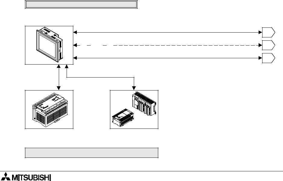
1.3System configuration
The system configuration to use the GOT is described below.
When the GOT is directly connected to the PLC :When the GOT is connected via a computer link unit, refer to |
|
|
Section 2. |
|
|
Data transfer cable FX-232CAB-1 (when the RS-232C connector in the personal |
|
|
F940GOT-SWD-E/LWD-E computer is 9-pin type) or Data transfer cable FX-232CAB-2 (when the RS-232C |
|
|
connector in the personal computer is half-pitch,14-pin type) |
1 |
|
Attach a ROM to the F9GT-40UMB, then connect it to a connector provided on the rear |
||
|
||
face of the GOT. |
2 |
|
|
Connection cable FX- 50DU-CAB0 for CPU port connection*1
Data transfer cable F2-232CAB-1
3
It cannot be used when a computer link (RS-232C communication) is used.
Connection cable FX-40DU-CAB *1
FX0/FX0S/FX0N/FX2N/
FX2NC Series
*1 |
FX/FX2C Series
A Series (except QnA) Motion controller
Connection cables of different length are available. (Refer to the options in "1.2 Product configuration".)
PC
1-14
F940GOT-SWD-E/LWD-E |
INTRODUCTION 1. |
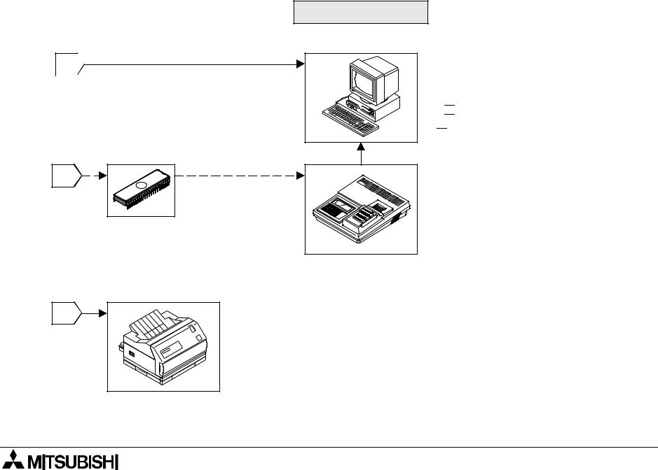
Peripheral units for GOT
1 
 Data transfer cable F2-232CAB-1 (when the RS-232C connector in the personal computer is 25-pin type)
Connected to RS-232C connector in GOT
General-purpose personal computer (screen creation software)
Screen creation software for DU FX- PCS-DU/WIN-E (V2.10 or later) Screen creation software for A900GOT SW 
 D5C-GOTRE-PACK
("  " is a numeric not less than 1.)
2 |
EPROM memory FX-EPROM-4M
(User screen data can be written using a general-purpose ROM writer.)
ROM writer General-purpose ROM writer
3 |
Printer
<Dedicated printers > GT-10A
K6PR(-K), A7(N)PR
<General-purpose printers > ESC/P
Printer equipped with RS-232C interface
(Prints out sampling data, alarm history and alarm messages.)
1-15
F940GOT-SWD-E/LWD-E |
INTRODUCTION 1. |
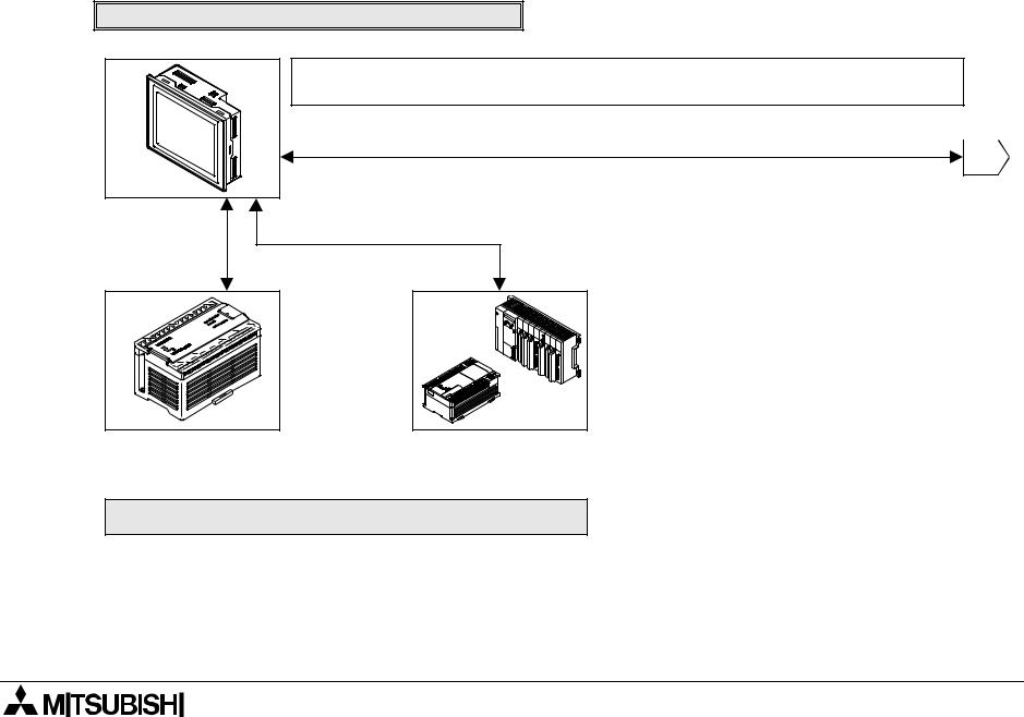
The figure below shows connection to peripheral units used to create sequence programs.
When built-in two-port interface function is used
F940GOT-SWD-E/LWD-E
When the two-port interface function is used, the operation environment should be set. (Refer to the description on "SERIAL PORT" on the SET-UP MODE screen.)
Data transfer cable FX-232CAB-1
(when the RS-232C connector in the personal computer is 9-pin type)  1
1 
Data transfer cable F2-232CAB-2 (when the RS-232C connector in the personal computer is half-pitch, 14-pin type)
Connected to RS-232C connector in GOT
Connection cable FX-
50DU-CAB0 for CPU Connection cable FX-40DU-CAB *1 port connection*1
FX0/FX0S/FX0N/FX2N/
FX2NC Series
FX/FX2C Series |
A Series (except QnA) Motion controller
*1 Connection cables of different length are available. (Refer to the options in "1.2 Product configuration".)
PC
1-16
F940GOT-SWD-E/LWD-E |
INTRODUCTION 1. |
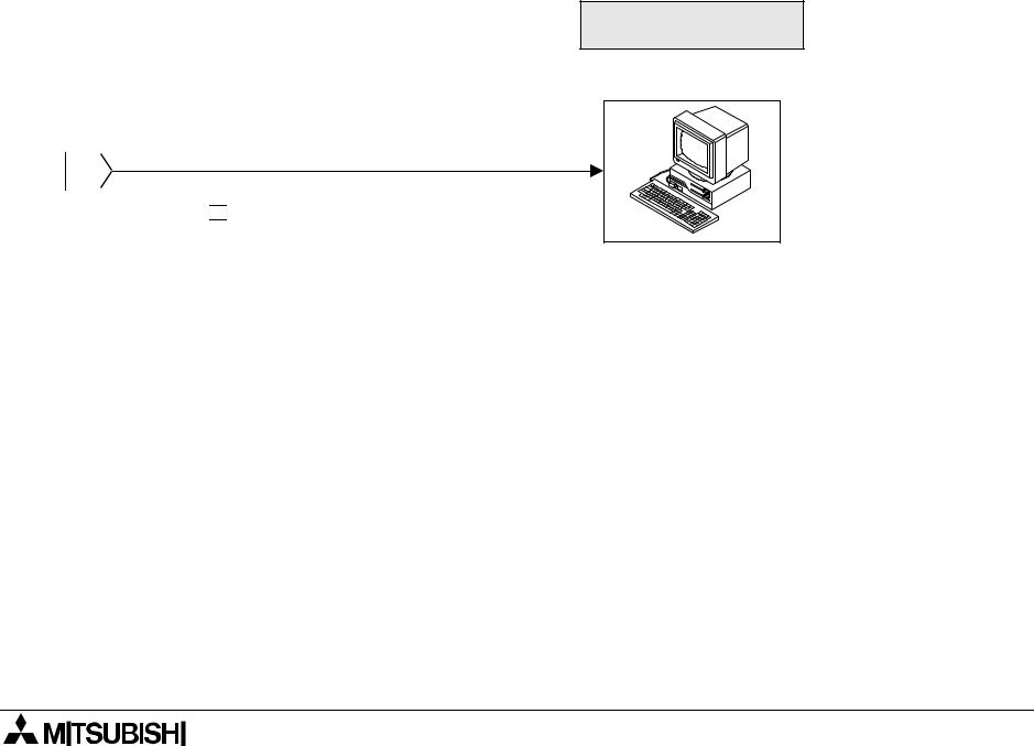
Peripheral unit to create sequence programs
General-purpose personal computer
*A general-purpose computer can be directly connected, and both the GOT and the personal computer can be used at
 the same time (without using the FX-2PIF). 1
 When the two-port interface function is used using the software package SW
 D5C(F)-GPPW-E, make sure to use the connection cable having the model name shown on the left to connect a personal computer.
Note:
This two-port interface function is effective in CPU port connection (via the RS-422). This function is not available in computer link connection (via the RS-422 or the RS-232C) and CPU port connection (via the RS-232C).
And even in CPU port connection (via the RS-422), this function is not available when two or more GOT units are connected (Refer to Paragraph 2.7.).
1-17

F940GOT-SWD-E/LWD-E |
INTRODUCTION 1. |
When the two-port interface FX-2PIF is used
F940GOT-SWD-E/LWD-E
Two-port interface |
|
Connection cable FX-40DU-CAB/EN |
|
||
FX-2PIF |
|
|
|
|
Data transfer cable |
FX-422CAB0 |
FX0/FX0S/FX0N/FX2N/
FX2NC Series
Program cable FX-20P-CAB
1
Data transfer cable AC30R4
2
Data transfer cable FX-422CAB or Data transfer cable FX-422CAB-150
FX/FX2C/ Series |
A Series (except QnA) |
1-18
F940GOT-SWD-E/LWD-E |
INTRODUCTION 1. |
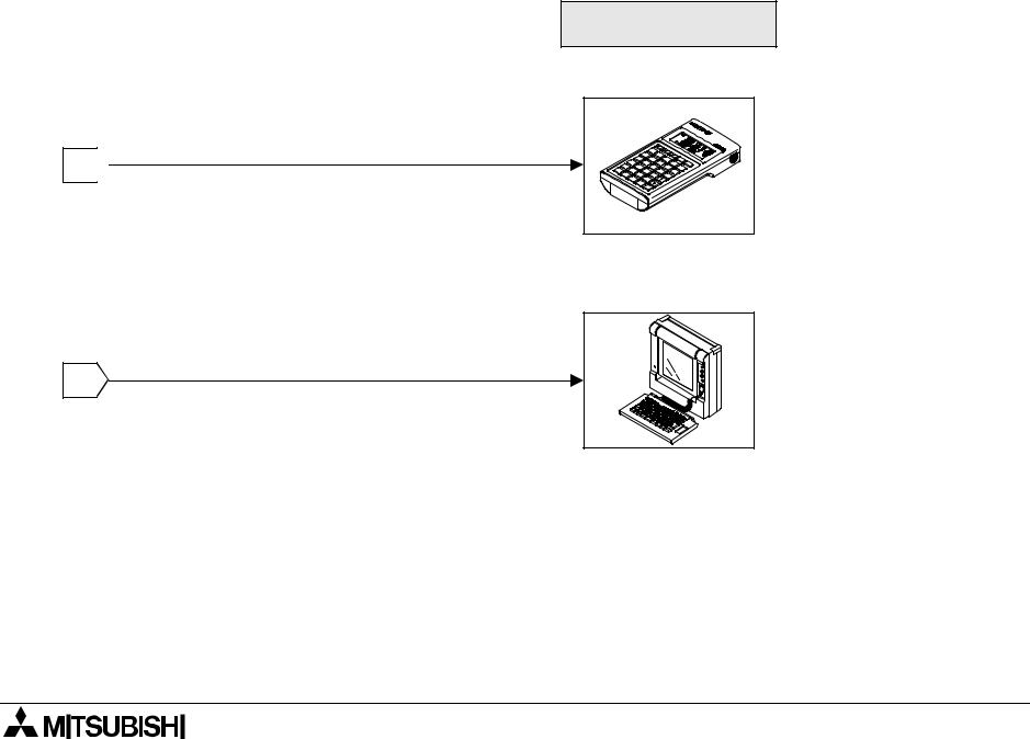
Peripheral unit to create sequence programs
Handy programming panel FX-10P-E/20P-E
1 
(A Series cannot be used.)
|
A7PHP/A7HGP |
|
A6GPP/A6PHP |
|
The FX2N/FX2NC Series |
|
can be used in the |
|
instruction/device |
2 |
range of the FX Series. |
Note:
The two-port interface FX-2PIF is available in CPU port connection (via the RS-422). This interface is not available in computer link connection (via the RS-422 or the RS-232C) and CPU port connection (via the RS-232C).
And even in CPU port connection (via the RS-422), this interface is not available when two or more GOT units are connected (Refer to Paragraph 2.7.).
1-19

F940GOT-SWD-E/LWD-E |
INTRODUCTION 1. |
1-20

F940GOT-SWD-E/LWD-E |
Installation, Wiring and General Specifications 2. |
2.Installation, Wiring and General Specifications
This section describes installation of the GOT and wiring of the power supply.
2.1Installation of main body
Caution on installation
• Use the unit in the environment for the general specifications described in the manual. Never use the unit in a place with dusts, soot, conductive dusts, corrosive gas or flammable gas, place exposed to high temperature, condensation or wind and rain or a place subject to vibrations or impacts.
If the unit is used in an unfavorable place described above, electrical shock, fire, malfunction, damages of the unit or deterioration of the unit may be caused.
•Never drop cutting chips and wiring chips into the ventilation window of the graphic operation terminal when you drill screw holes or perform the wiring work.
Fire, failure or malfunction may be caused.
•Connect a connection cable and mount an extension module securely to the specified connectors respectively while the power is turned off.
Imperfect connection may cause malfunction.
2-1

F940GOT-SWD-E/LWD-E |
Installation, Wiring and General Specifications 2. |
The GOT is to be embedded in a panel. Perform the installation procedure described below.
1) Machining the mounting panel face |
|
) |
|
||
|
|
|
On the panel face, drill a mounting hole of the dimensions |
|
+0.04 0.00- |
|
|
|
shown on the right. |
mm |
(4.76 |
|
||
* Make sure that the plate thickness of the mounting panel |
(inches) |
+1 -0 |
|
||
is 5 mm (0.2 inches) or less. |
|
121 |
|
|
|
|
|
|
|
153 -+10 (6.02 -+0.040.00 ) |
|
2) Inserting the GOT into the panel face |
|
a) |
Attach a packing to the GOT. Insert the GOT from the front |
b) |
|
|
|
|
of the panel face. |
|
|
a) GOT
b)Packing
c)Mounting hole
c)
2-2
 Loading...