


V51LCD
DiamondPoint
DPLCD51V71V91VCover.p65 11/19/04, 2:57 PM1
TM
V51LCD/V71LCD/V91LCD

Index
Warning .................................................................................................................... 1
Contents ................................................................................................................. 2
Quick Start ............................................................................................................. 3
Controls ...................................................................................................................7
Recommended Use .............................................................................................. 10
Specifications .......................................................................................................12
Features ................................................................................................................ 15
Troubleshooting ................................................................................................... 16
References .............................................................................................................17
Limited Warranty .................................................................................................18
TCO ‘99 ................................................................................................................... 19
Avertissement ..................................................................................................... 22
Contenu ................................................................................................................. 23
Mise en marche rapide ...................................................................................... 24
Commandes .......................................................................................................... 28
Usage recommandé ............................................................................................. 31
Fiche technique ................................................................................................... 33
Fonctions ............................................................................................................. 36
Dépannage ............................................................................................................ 37
Références ........................................................................................................... 38
Garantie limitée .................................................................................................. 39
TCO ‘99 .................................................................................................................. 40
DPLCD51V71V91VCover.p65 11/19/04, 2:57 PM2
WARNING
TO PREVENT FIRE OR SHOCK HAZARDS, DO NOT EXPOSE THIS UNIT TO RAIN OR MOISTURE. ALSO, DO NOT USE
THIS UNIT'S POLARIZED PLUG WITH AN EXTENSION CORD RECEPTACLE OR OTHER OUTLETS UNLESS THE PRONGS
CAN BE FULLY INSERTED.
REFRAIN FROM OPENING THE CABINET AS THERE ARE HIGH VOLTAGE COMPONENTS INSIDE. REFER SERVICING
TO QUALIFIED SERVICE PERSONNEL.
CAUTION
CAUTION: TO REDUCE THE RISK OF ELECTRIC SHOCK, MAKE SURE POWER CORD IS UNPLUGGED FROM
WALL SOCKET. TO FULLY DISENGAGE THE POWER TO THE UNIT, PLEASE DISCONNECT THE POWER
CORD FROM THE AC OUTLET. DO NOT REMOVE COVER (OR BACK). NO USER SERVICEABLE PARTS
INSIDE. REFER SERVICING TO QUALIFIED SERVICE PERSONNEL.
This
symbol warns user that uninsulated voltage within the unit may have sufficient magnitude to cause
electric shock. Therefore, it is dangerous to make any kind of contact with any part inside this unit.
This symbol alerts the user that important literature concerning the operation and maintenance of this
unit has been included. Therefore, it should be read carefully in order to avoid any problems.
Canadian Department of Communications Compliance Statement
DOC: This Class B digital apparatus meets all requirements of the Canadian
Interference-Causing Equipment Regulations.
C-UL: Bears the C-UL Mark and is in compliance with Canadian Safety Regulations
according to
CAN/CSA C22.2 No. 60950-1.
FCC Information
1.
Use the attached specified cables with the
V71LCD (L174F1), or DiamondPoint V91 LCD (L194F2)
with radio and television reception.
(1)
Please use the supplied power cord or equivalent to ensure FCC compliance.
(2) Please use the supplied shielded video signal cable.
Use of other cables and adapters may cause interference with radio and
television reception.
2.
This equipment has been tested and found to comply with the limits for a Class B digital
device, pursuant to part 15 of the FCC Rules. These limits are designed to provide
reasonable protection against harmful interference in a residential installation. This
equipment generates, uses, and can radiate radio frequency energy, and, if not installed
and used in accordance with the instructions, may cause harmful interference to radio
communications. However, there is no guarantee that interference will not occur in a
particular installation. If this equipment does cause harmful interference to radio or
television reception, which can be determined by turning the equipment off and on, the user
is encouraged to try to correct the interference by one or more of the following measures:
• Reorient or relocate the receiving antenna.
• Increase the separation between the equipment and receiver.
• Connect the equipment into an outlet on a circuit different from that to which the receiver
is connected.
• Consult your dealer or an experienced radio/TV technician for help.
Changes or modifications not expressly approved by the party responsible for
compliance could void the user’s authority to operate the equipment.
If necessary, the user should contact the dealer or an experienced radio/television technician
for additional suggestions. The user may find the following booklet, prepared by the Federal
Communications Commission, helpful: ”How to Identify and Resolve Radio-TV Interference
Problems.“ This booklet is available from the U.S. Government Printing Office, Washington,
D.C., 20402, Stock No. 004-000-00345-4.
DiamondPoint V51LCD (L154F0), DiamondPoint
color monitor so as not to interfere
1
DP51V71V91VManual112304.p65 11/29/04, 3:36 PM1

Contents
Your new Mitsubishi DiamondPoint LCD monitor box* should
contain the following:
• D iamondPoint LCD monitor
• P ower Cord
• User’s Manua
• Video Signal Cable
• Base Stand
• Cable Holder
Power Cord
l
Video Signal Cable
TM
DiamondPoint
V51LCD/V71LCD/V91LCD
User’s Manual
*Remember to save your original box and packing material to transport or ship the monitor.
DP51V71V91VManual112304.p65 11/29/04, 3:36 PM2
Cable Holder
2
DiamondPoint
LCD Monitor
(Stand not connected)
Quick Start
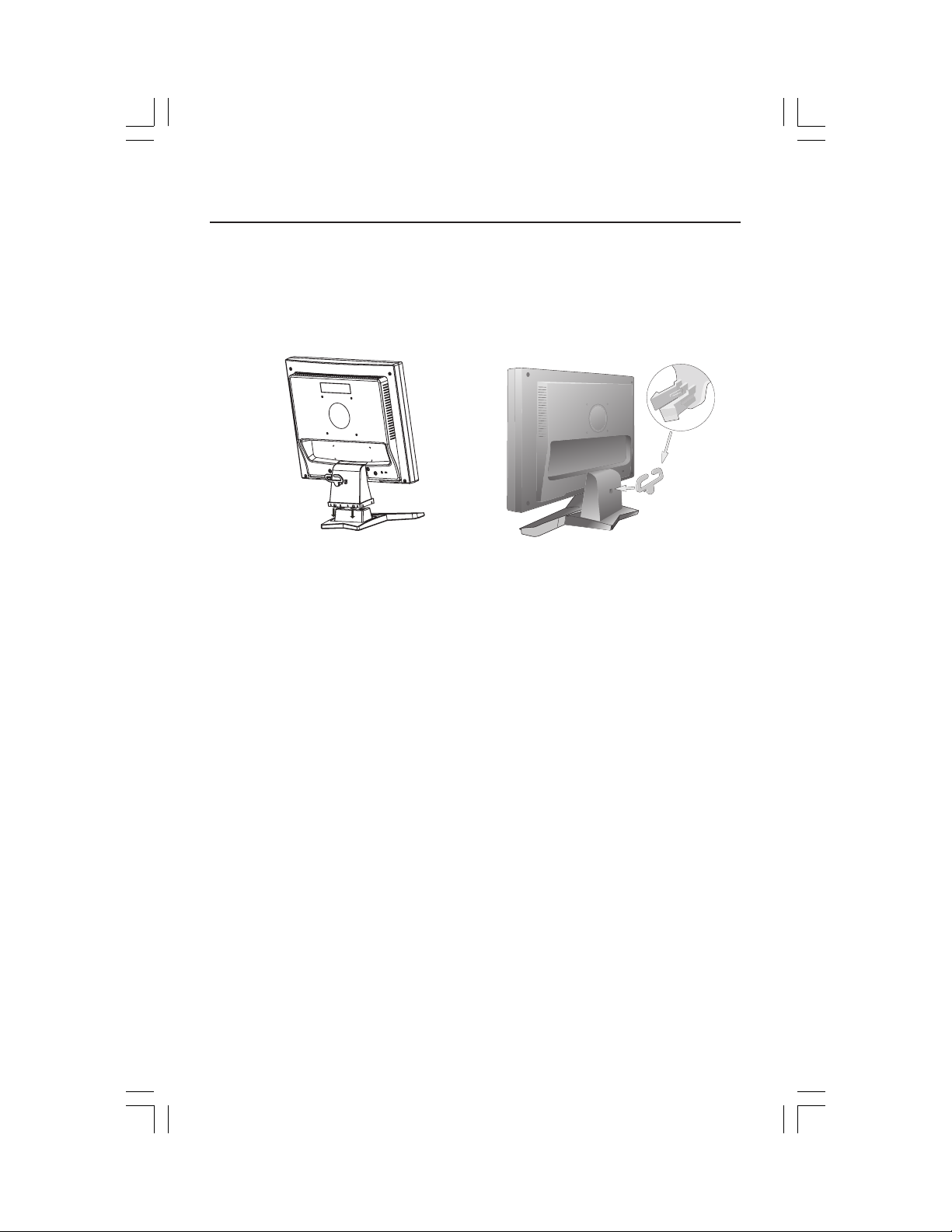
To attach the Base to the LCD Stand:
1. Insert the front of the LCD Stand into the holes in the front of the Base (Figure 1).
2. Next, position the locking tabs on the back side of the LCD Stand with the holes on the
Base. Lower the Stand until locking tabs are secure.
3. Attach the clip into the base (Figure 2).
Figure 1 Figure 2
Stand
Locking Tabs
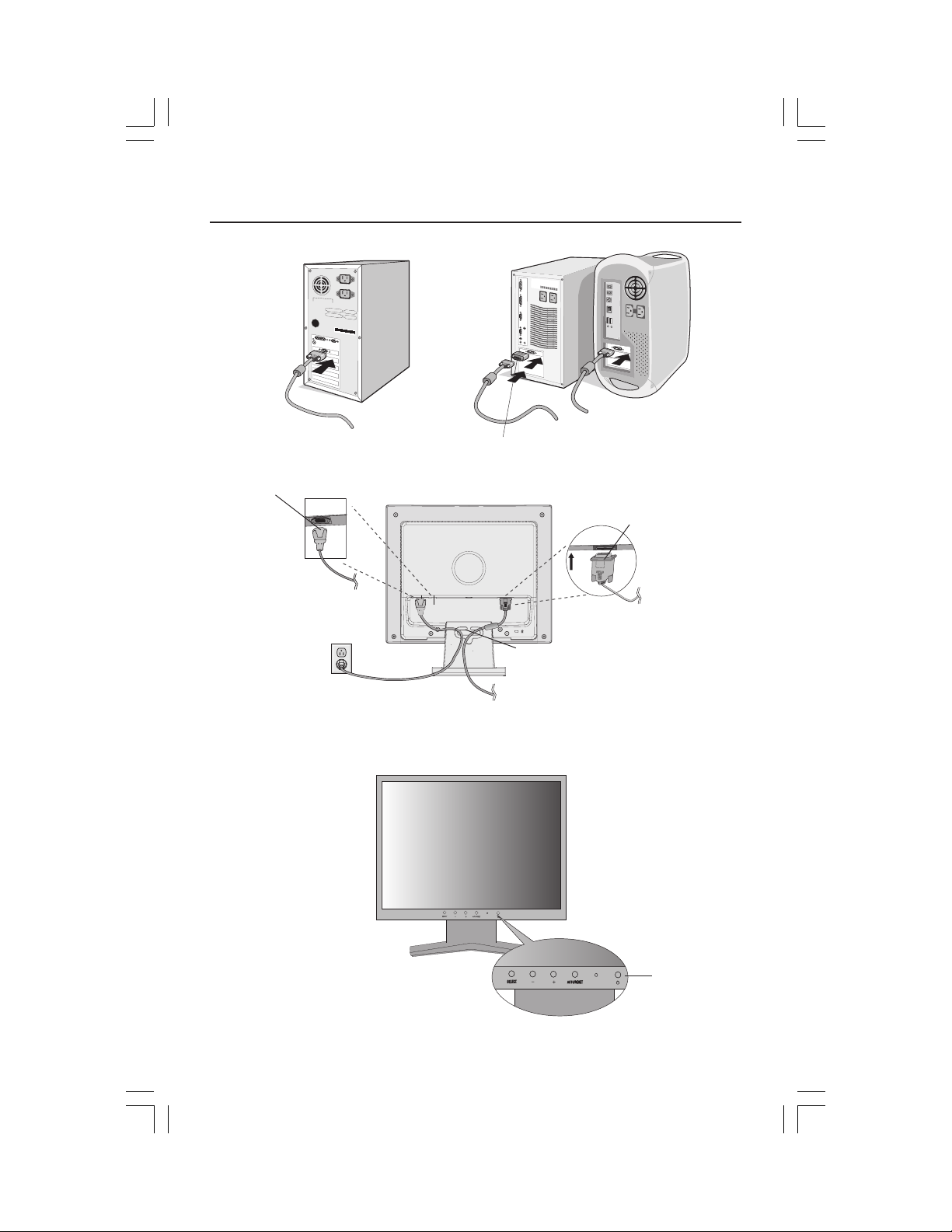
To attach the DiamondPoint LCD monitor to your system, follow these instructions:
1. Turn off the power to your computer.
2. For the PC with Analog output: Connect the 15-pin mini D-SUB signal cable to the
connector of the display card in your system (Figure A.1). Tighten all screws.
For the MAC: Connect the Macintosh cable adapter to the computer, then attach the
15-pin mini D-SUB signal cable to the Macintosh cable adapter (Figure A.2). Tighten
all screws.
NOTE: To obtain the Macintosh cable adapter, call NEC-Mitsubishi Electronics Display of
America, Inc. at (800) 632-4662.
3. Connect the 15-pin mini D-SUB of the video signal cable to the appropriate connector
on the back of the monitor (Figure B.1).
4. Connect one end of the power cord to the LCD and the other end to the power outlet.
Place the video signal cable and power cord between the cable holder (Figure B.1).
NOTE: Adjust the position of cables between the holder to avoid damage.
NOTE: If you use this monitor at AC125-240V, please refer to Recommended Use
section of this manual for proper selection of power cord.
5. Turn on the monitor with the front power button and the computer. (Figure C.1)
6. No-touch Auto Adjust automatically adjusts the monitor to optimal settings upon initial
setup for most timings. For further adjustments, use the following OSD
• Auto Adjust Contrast • Auto Adjust
Refer to the Controls section of this User’s Manual for a full description of these
OSD controls.
NOTE: For download information on the Windows® 95/98/Me/2000/XP INF file for your
DiamondPoint monitor, refer to the References section of this User’s Manual.
NOTE: If you have any problems, please refer to the Troubleshooting section of this User’s Manual.
Front Base
®
controls:
3
DP51V71V91VManual112304.p65 11/29/04, 3:36 PM3
Quick Start –continued
Figure A.1
Power Cable
Figure B.1
Figure A.2
Macintosh Cable
Adapter
(not included)
Note: Some Macintosh
systems do not require a
MacintoshCable Adapter
Input (VGA)
Cable holder
Figure C.1
DP51V71V91VManual112304.p65 11/29/04, 3:36 PM4
Power button
4
Quick Start –continued
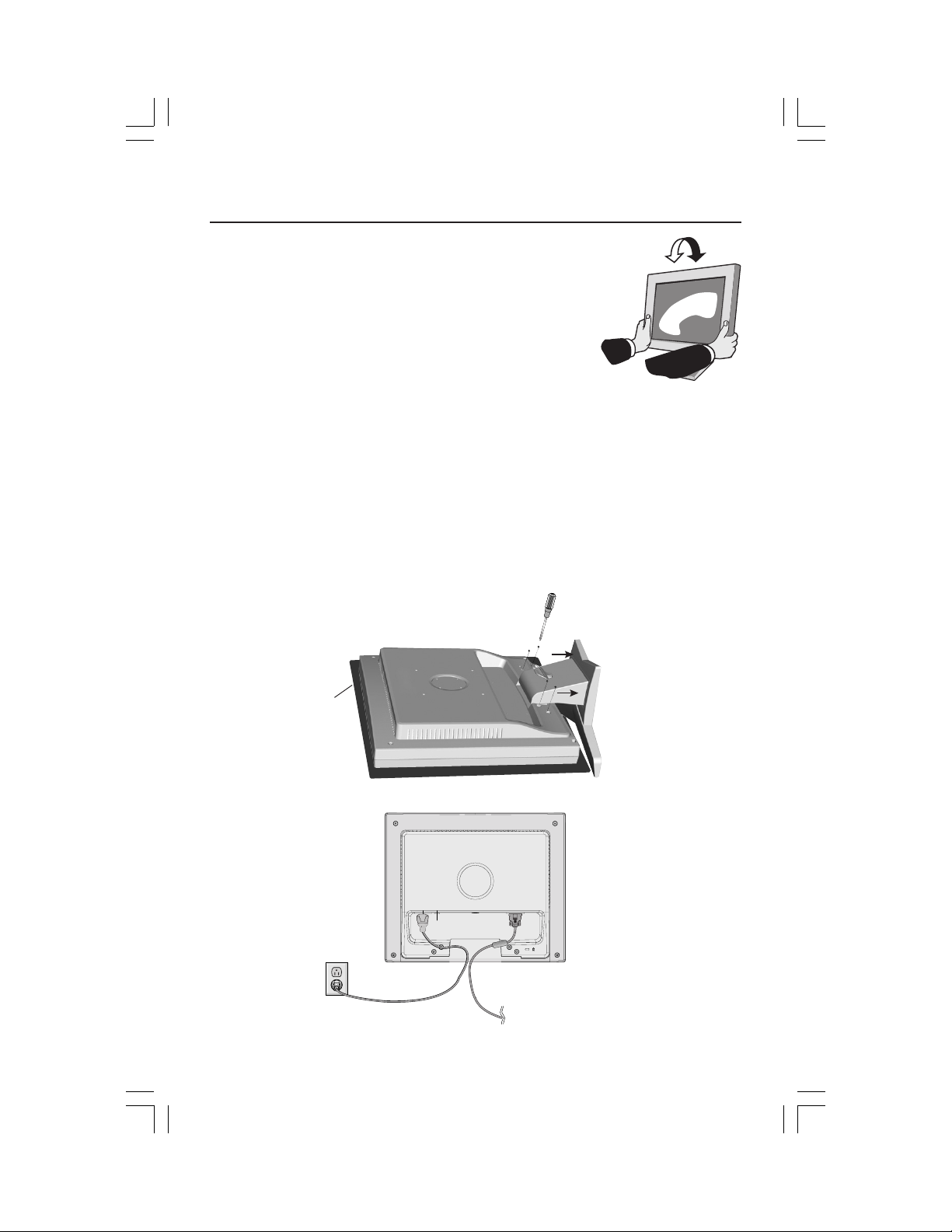
Tilt
Grasp both sides of the monitor screen with your hands
and adjust the tilt as desired (Figure TS.1).
NOTE: Handle with care when tilting the monitor screen.
Remove Monitor Stand for Mounting
To prepare the monitor for alternate mounting purposes:
1.Disconnect all cables.
2.Place monitor face down on a nonabrasive surface (Figure R.1).
3.Remove the 4 screws connecting the monitor to the stand and slide the
stand off from the LCD (Figure R.1).
The monitor is now ready for mounting in an alternate manner.
4.
Connect the AC cord and signal cable to the back of the monitor (Figure R.2).
5. Reverse this process to reattach stand.
NOTE: Use only VESA-compatible alternative mounting method.
NOTE: Handle with care when removing monitor stand.
Figure R.1
Figure TS.1
non-abrasive
surface
Figure R.2
DP51V71V91VManual112304.p65 11/29/04, 3:36 PM5
5
Quick Start –continued
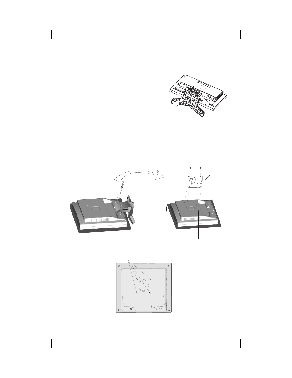
Removing the Base
Note: Always remove the Base when shipping the
LCD.
1.
Place monitor face down on a non-abrasive
surface.
2. While using your thumbs, press the tabs in the
direction of the arrows to unlock the stand.
3. Pull the unlocked base off the stand.
Connecting a Flexible Arm
This LCD monitor is designed for use with a flexible arm. Please use the attached
screws (4pcs) as shown in the picture when installing.
To meet the safety requirements, the monitor must be mounted to an arm which
guaranties the necessary stability under consideration of the weight of the monitor.
The LCD monitor should only be used with an approved arm (e.g. GS mark).
Replace screws
Thickness of
Bracket (Arm)
2.0~3.2 mm
Tighten all
screws.
Specifications
4-SCREWS (M4)
(MAX depth: 8.5 mm)
If using other screws,
check depth of holes.
DP51V71V91VManual112304.p65 11/29/04, 3:36 PM6
75 mm (V51LCD)
100 mm (V71LCD)
100 mm (V91LCD)
6
75 mm (V51LCD)
100 mm (V71LCD)
100 mm (V91LCD)
Weight of LCD assembly:
2.8 kg - V51LCD (MAX)
4.2 kg - V71LCD (MAX)
5.5 kg - V91LCD (MAX)
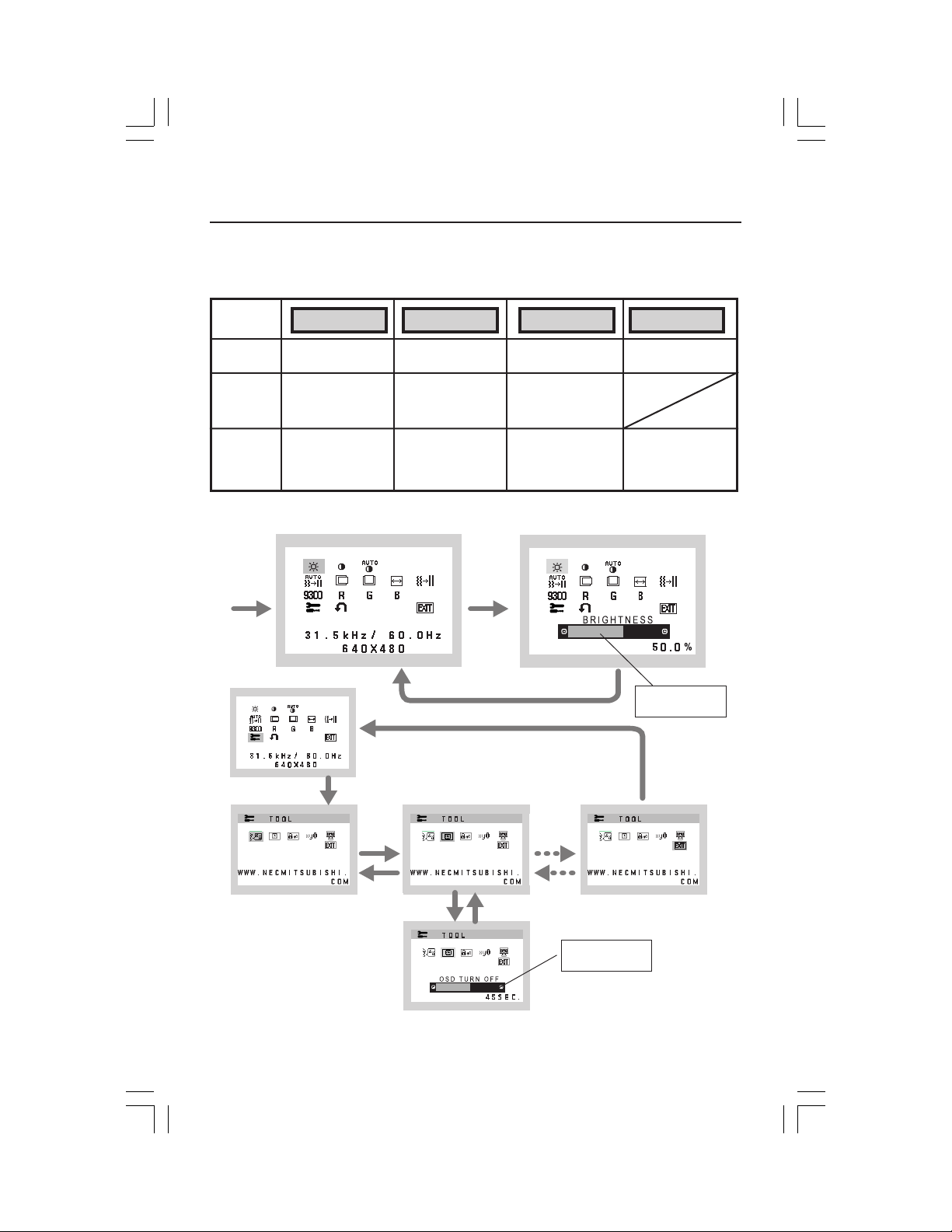
Controls
OSD (On-Screen Display) control buttons on the front of the
monitor function as follows:
1. Basic key function
Button
OSD Off
OSD On
(Icon selection
stage)
OSD On
(Adjustment
stage)
OSD displayed
Go to Adjustment
stage
Go to Icon selection
stage
2. OSD structure
Main Menu (Icon Select)
Press
“SELECT”
key
SELECT
–+AUTO / RESET
Shortcut to bright
adjust window
Cursor moves left
Adjust value
decrease or
Cursor for adjust
moves left
“SELECT”
Press “SELECT” key
Press “SELECT” key
Shortcut to contrast
adjust window
Cursor moves right
Adjust value
increase or
Cursor for adjust
moves right
Press
key
Main Menu (Adjust)
“Auto adjust“
function
Reset operation
Adjust by using
“–“ or “ +”.
Press “SELECT”
key
Press
“–“ or “ +”
Sub Menu (Icon Select)
DP51V71V91VManual112304.p65 11/29/04, 3:36 PM7
Press
“–“ or “ +”
Press “SELECT” key
Adjust by using
“–“ or “ +”.
Sub Menu (Adjust)
7
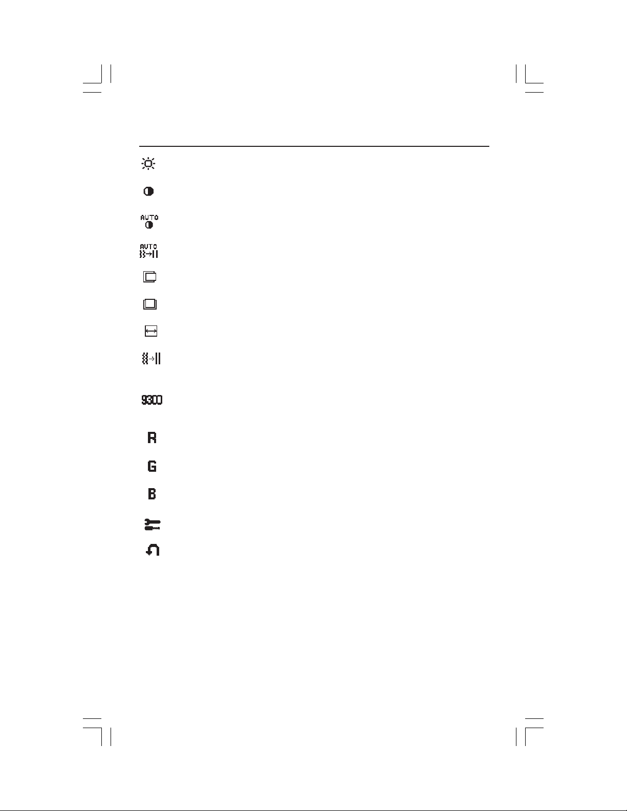
Controls –continued
BRIGHTNESS
Adjusts the overall image and background screen brightness.
CONTRAST
Adjusts the image brightness in relation to the background.
AUTO CONTRAST
Adjusts the image displayed for non-standard video inputs.
AUTO ADJUST
Automatically adjusts the Image Position, H. Size and Fine setting.
LEFT/RIGHT
Controls Horizontal Image Position within the display area of the LCD.
DOWN/UP
Controls Vertical Image Position within the display area of the LCD.
H. SIZE
Adjusts the horizontal size by increasing or decreasing this setting.
FINE
Improves focus, clarity and image stability by increasing or decreasing
this setting.
COLOR CONTROL SYSTEMS
Four color presets (9300/7500/6500/USER) select the desired color
setting.
COLOR RED
Increase or decreases Red. The change will appear on screen.
COLOR GREEN
Increase or decreases Green. The change will appear on screen.
COLOR BLUE
Increase or decreases Blue. The change will appear on screen.
TOOL
Selecting TOOL allows you to get into the sub menu.
FACTORY PRESET
Selecting Factory Preset allows you to reset all OSD control settings back
to the factory settings. The RESET button will need to be held down for
several seconds to tage effect. Individual settings can be reset by
highlighting the control to be reset and pressing the RESET button.
DP51V71V91VManual112304.p65 11/29/04, 3:36 PM8
8
Controls –continued
EXIT
Selecting EXIT allows you exit OSD menu/sub menu.
LANGUAGE
OSD control menus are available in seven languages.
OSD TURN OFF
The OSD control menu will stay on as long as it is in use. In the OSD
Turn OFF submenu, you can select how long the monitor waits after
the last touch of a button to shut off the OSD control menu. The preset
choices are 10 - 120 seconds in 5 second intervals.
OSD LOCK OUT
This control completely locks out access to all OSD control functions
without Brightness and Contrast. When attempting to activate OSD
controls while in the Lock Out mode, a screen will appear indicating
the OSD are locked out. To activate the OSD Lock Out function, press
“AUTO/ RESET“, then “+“ key and hold down simultaneously. To deactivate the OSD Lock Out, press “AUTO/ RESET“, then “+“ key and
hold down simultaneously.
RESOLUTION NOTIFIER
If ON is selected, a message will appear on the screen after 30
seconds, notifying you that the resolution is not at optimal resolution.
MONITOR INFO
Indicates the model and serial numbers of your monitor.
OSD® Warning: OSD Warning menus disappear with SELECT button.
NO SIGNAL: This function gives a warning when there is no signal present.
After power is turned on or when there is a change of input signal or video
is inactive, the
RESOLUTION NOTIFIER: This function gives a warning of use with
optimized resolution. After power is turned on or when there is a change
of input signal or the video signal doesn’t have proper resolution, the
Resolution Notifier window will open. This function can be disabled in
the TOOL menu.
OUT OF RANGE: This function gives a recommendation of the optimized
resolution and refresh rate. After the power is turned on or there is a change
of input signal or the video signal doesn’t have proper timing, the
Range
DP51V71V91VManual112304.p65 11/29/04, 3:36 PM9
No Signal window will appear.
menu will appear.
Out Of
9
Recommended Use
Safety Precautions and Maintenance
FOR OPTIMUM PERFORMANCE, PLEASE NOTE THE
FOLLOWING WHEN SETTING UP AND USING
THE DIAMONDPOINT LCD COLOR MONITOR:
• DO NOT OPEN THE MONITOR. There are no user serviceable parts inside and opening or
removing covers may expose you to dangerous shock hazards or other risks. Refer all servicing to
qualified service personnel.
• Do not spill any liquids into the cabinet or use your monitor near water.
• Do not insert objects of any kind into the cabinet slots, as they may touch dangerous voltage
points, which can be harmful or fatal or may cause electric shock, fire or equipment failure.
• Do not place any heavy objects on the power cord. Damage to the cord may cause shock or fire.
• Do not place this product on a sloping or unstable cart, stand or table, as the monitor may fall,
causing serious damage to the monitor.
• When operating the DiamondPoint LCD monitor with its AC 125-240V power supply, use a
power supply cord that matches the power supply voltage of the AC power outlet being used. The
power supply cord you use must have been approved by and comply with the safety standards of
your country. (Type H05VV-F should be used in Europe)
• In UK, use a BS-approved power cord with molded plug having a black (5A) fuse installed for use
with this monitor. If a power cord is not supplied with this monitor, please contact your supplier.
• Do not place any objects onto the monitor and do not use the monitor outdoors.
• The inside of the fluorescent tube located within the LCD monitor contains mercury.
Please follow the bylaws or rules of your municipality to dispose of the tube properly.
• Do not bend power cord.
• Do not use monitor in high temperature, humid, dusty, or oily areas.
• If glass is broken, handle with care.
• Do not cover vent on monitor.
Immediately unplug your monitor from the wall outlet and refer servicing to qualified service
personnel under the following conditions:
• When the power supply cord or plug is damaged.
• If liquid has been spilled, or objects have fallen into the monitor.
• If the monitor has been exposed to rain or water.
• If the monitor has been dropped or the cabinet damaged.
• If the monitor does not operate normally by following operating instructions.
• If monitor or glass is broken, do not come in contact with the liquid crystal and handle with care.
• Allow adequate ventilation around the monitor so that heat can properly dissipate. Do
not block ventilated openings or place the monitor near a radiator or other heat
sources. Do not put anything on top of monitor.
• The power cable connector is the primary means of detaching the system from the
CAUTION
Image Persistence
Please be aware that LCD Technology may experience a phenomenon known as Image Persistence.
Image Persistence occurs when a residual or “ghost” image of a previous image remains visible on
the screen. Unlike CRT monitors, LCD monitors’ Image Persistence is not permanent, but constant
images being displayed for a long period of time should be avoided.
To alleviate Image Persistence,
example, if an image was on the monitor for one hour and a residual image remains, the monitor should
be turned off for one hour to erase the image.
As with all personal display devices, NEC-Mitsubishi Electronics Display recommends displaying moving
images and using a moving screen saver at regular intervals whenever the screen is idle, or turning off the
monitor when not in use.
power supply. The monitor should be installed close to a power outlet which is easily accessible.
• Handle with care when transporting. Save packaging for transporting.
turn off the monitor for as long as the previous image was displayed. For
10
DP51V71V91VManual112304.p65 11/29/04, 3:36 PM10
Recommended Use –continued
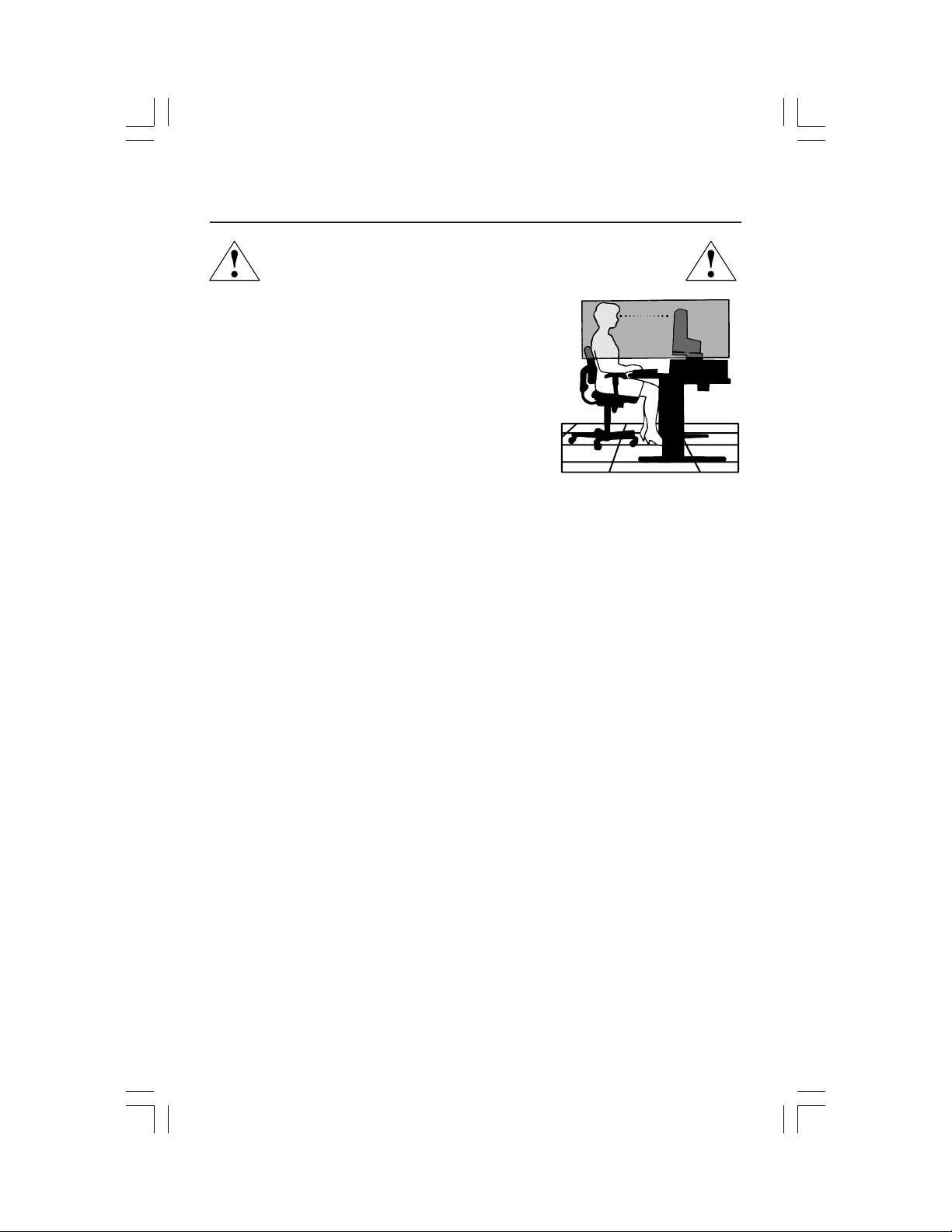
CORRECT PLACEMENT AND ADJUSTMENT OF THE MONITOR
CAN REDUCE EYE, SHOULDER AND NECK FATIGUE. CHECK THE
FOLLOWING WHEN YOU POSITION THE MONITOR:
• For optimum performance, allow 20 minutes for
warm-up.
• Adjust the monitor height so that the top of the
screen is at or slightly below eye level. Your eyes
should look slightly downward when viewing the
middle of the screen.
•
Position your monitor no closer than 16 inches
and no further away than 28 inches from your
eyes. The optimal distance is 20 inches.
• Rest your eyes periodically by focusing on an
object at least 20 feet away. Blink often.
• Position the monitor at a 90° angle to windows and other light sources to
minimize glare and reflections. Adjust the monitor tilt so that ceiling lights do
not reflect on your screen.
• If reflected light makes it hard for you to see your screen, use an antiglare filter.
• Clean the LCD monitor surface with a lint-free, nonabrasive cloth. Avoid using
any cleaning solution or glass cleaner!
• Adjust the monitor’s brightness and contrast controls to enhance readability.
• Use a document holder placed close to the screen.
• Position whatever you are looking at most of the time (the screen or
reference material) directly in front of you to minimize turning your head
while you are typing.
• Avoid displaying fixed patterns on the monitor for long periods of time to avoid
image persistence (afterimage effects).
• Get regular eye checkups.
Ergonomics
To realize the maximum ergonomics benefits, we recommend the following:
•
Use the preset Size and Position controls with standard signals
•
Use the preset Color Setting
•
Use non-interlaced signals with a vertical refresh rate between 60-75Hz
•
Do not use primary color blue on a dark background, as it is difficult to see and
may produce eye fatigue to insufficient contrast
For more detailed information on setting up a healthy work environment, write the
American National Standard for Human Factors Engineering of Visual Display Terminal
Workstations – ANSI-HFS Standard No. 100-1988 – The Human Factors Society, Inc.
P.O. Box 1369, Santa Monica, California 90406.
11
DP51V71V91VManual112304.p65 11/29/04, 3:36 PM11
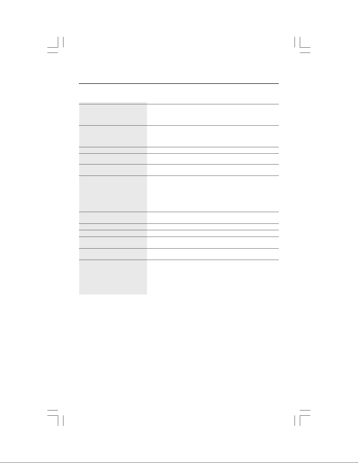
Specifications
Monitor DiamondPoint Notes
Specifications V51LCD Monitor
LCD Module Diagonal: 15.0 inch Active matrix; thin film transistor (TFT)
Input Signal Video: ANALOG 0.7 Vp-p/75 Ohms
Display Colors Analog input: 16,194,277 Depending on display card used.
Maximum Left/right: 60°/60° (CR>10)
Viewing Angles Up/Down: 45°/45° (CR>10)
Synchronization Horizontal: 31.5 kHz to 61 kHz Automatically
Range Vertical: 55 Hz to 76 Hz Automatically
Resolutions Supported 720 x 400*
Active Display Area Horizontal :
Power Supply
Current Rating 0.5 - 0.3 A/100-240V
Dimensions
Weight 3.2 kg
Environmental Considerations
Viewable Image Size: 15.0 inch liquid crystal display (LCD); 0.297 mm dot
Native Resolution (Pixel Count): 1024 x 768 pitch; 250cd/m
Sync: Separate sync TTL Level (Positive/Negative)
Horizontal sync Positive/Negative
Vertical sync Positive/Negative
1
-240 V
:VGA text
1
at 75 Hz
~50/60 Hz
640 x 480*1 at 60 Hz to 75 Hz
800 x 600*1 at 56 Hz to 75 Hz
832 x 624*
1024 x 768 at 60 Hz to 75 Hz ..................
Vertical :
Operating Temperature: 5°C to 35°C/41°F to 95°F
Humidity: 30% to 80%
Storage Temperature: -10°C to 60°C/14°F to 140°F
Humidity: 10% to 85%
304.1 mm/12.0 inches
228.1 mm/9.0 inches
100
344.6 mm (W) x 352.7 mm (H) x 167.0 mm (D)
13.6 inches (W) x 13.9 inches (H) x 6.6 inches (D)
7.1 lbs
Feet: 0 to 10,000 Feet
Feet: 0 to 40,000 Feet
400:1 contrast ratio, typical
Some systems may not support
all modes listed.
NEC-Mitsubishi Electronics Display cites
recommended resolution at 75 Hz for
optimal display performance.
2
white luminence;
*1 Interpolated Resolutions: When resolutions are shown that are lower than the pixel count of the LCD module, text may appear different. This is
normal and necessary for all current flat panel technologies when displaying nonnative resolutions full screen. In flat panel technologies, each
dot on the screen is actually one pixel, so to expand resolutions to full screen, an interpolation of the resolution must be done.
NOTE: Technical specifications are subject to change without notice.
12
DP51V71V91VManual112304.p65 11/29/04, 3:36 PM12
 Loading...