


 Loading...
Mitsubishi V45CB, V45CA, V45C, WD-82840, WD-73840 User Manual
...Version 3.0 10/13/11 Service2011
Manual
DLP PROJECTION HDTV
V45C |
V45 |
V45CA |
WD-73C11 WD-73640 |
WD-73CA1 |
|
V45+ |
V45++ |
V45CB |
WD-73740 |
WD-73840 |
WD-82CB1 |
WD-82740 |
WD-82840 |
|
|
WD-92840 |
|
CAUTION:
Before servicing this chassis, it is important that the service person read the "SAFETY PRECAUTIONS" and "PRODUCT SAFETY NOTICE" contained in this manual.
SPECIFICATIONS
• Power Input |
: AC 120V, 60Hz |
• Light Engine |
: DLP™ (1080p) |
• Light Source |
: VIP Lamp |
• Antenna Input |
: RF 75 unbalanced |
• Tuning |
: NTSC/ATSC/QAM |
: |
Analog Cable - 1~125 |
|
Digital Cable - 1~135 |
• Speakers |
: 10W x 2 (except V45++) |
|
: 2W x 16 (V45++) |
•See Page 5 for additional specifications.
•Design specifications are subject to change without notice.
• Analog Input : Composite/Component Level (RCA Type)
Y/Video: 1.0 Vp-p, Cr, Cb: 700mVp-p 75 unbalanced
:AUDIO IN JACK (RCA Type) -4.7dBm 43k unbalanced
•Analog Output : AUDIO / SUBWOOFER OUT JACK
Level |
|
(RCA Type) |
|
|
-4.7dBm 4.7k unbalanced |
• Digital |
: AC-3/PCM Digital Audio Output |
|
Inputs/Outputs |
|
(RCA Type) |
|
: |
HDMI™ |
|
: |
USB |
|
: |
PC - use HMDI™ |
|
: |
Wired IR Input/Output (V45++) |
|
: |
Ethernet (V45CB, V45+, V45++) |
|
: |
Bluetooth (V45++) |
MITSUBISHI ELECTRIC VISUAL SOLUTIONS AMERICA, INC.
9351 Jeronimo Road, Irvine, CA 92618-1904
Copyright © 2011 Mitsubishi Electric Visual Solutions America, Inc.
All Rights Reserved

MODELS: WD-73640 / WD-73740 / WD-73840 / WD-73C11 / WD-73CA1 / |
|
WD-82740 / WD-82840 / WD-82CB1 / WD-92840 |
|
CONTENTS |
|
INTRODUCTION.................................................................................................................................. |
5 |
Dimensions, weight, power usage, etc............................................................................................. |
5 |
PRODUCT SAFETY NOTICE.............................................................................................................. |
5 |
SAFETY PRECAUTIONS.................................................................................................................... |
6 |
DISASSEMBLY & PARTS REPLACEMENT...................................................................................... |
7 |
Back Cover Removal........................................................................................................................ |
7 |
Chassis Removal ............................................................................................................................ |
8 |
Rear Terminal Cover Removal......................................................................................................... |
8 |
PWB-POWER Removal ................................................................................................................... |
9 |
PWB-MAIN Removal........................................................................................................................ |
9 |
PWB-BALLAST Removal ............................................................................................................... |
10 |
Optical Engine Assembly Removal & Disassembly ....................................................................... |
10 |
Optical Engine Replacement.......................................................................................................... |
13 |
Projection Lens Replacement ........................................................................................................ |
14 |
Color Wheel Replacement ............................................................................................................. |
15 |
Screen Replacement...................................................................................................................... |
16 |
Mirror Replacement........................................................................................................................ |
20 |
SERVICE PROCEDURES ................................................................................................................. |
23 |
Remote Control .............................................................................................................................. |
23 |
Option Menu................................................................................................................................... |
24 |
Reset and Initialization ................................................................................................................... |
26 |
LED Indications & Self Diagnostics................................................................................................ |
27 |
Error Codes .................................................................................................................................... |
28 |
Error Code Log............................................................................................................................... |
28 |
Sound Projector Transducer Test .................................................................................................. |
29 |
Service Adjustments....................................................................................................................... |
30 |
Equipment & Test Signals..................................................................................................... |
30 |
Service Menu ........................................................................................................................ |
30 |
Horizontal & Vertical Position Adjustment............................................................................. |
31 |
Index Delay Adjustment ........................................................................................................ |
31 |
Manual Geometry Alignment................................................................................................. |
32 |
Data Transfer Functions................................................................................................................. |
36 |
Using Lead Free Solder ................................................................................................................. |
37 |
Chip Parts Replacement ................................................................................................................ |
38 |
REPLACEMENT PARTS................................................................................................................... |
39 |
Safety Critical Parts Designation.................................................................................................... |
39 |
Fuse Replacement Warning........................................................................................................... |
39 |
Parts Quick Reference ................................................................................................................... |
40 |
Service Parts List ........................................................................................................................... |
41 |
Screen Parts................................................................................................................................... |
46 |
Mirror Kits & Preparation ................................................................................................................ |
48 |
CIRCUIT BLOCK DIAGRAMS .......................................................................................................... |
50 |
SCHEMATIC DIAGRAMS ................................................................................................................. |
56 |
Version 3.0
Page 3

MODELS: WD-73640 / WD-73740 / WD-73840 / WD-73C11 / WD-73CA1 /
WD-82740 / WD-82840 / WD-82CB1 / WD-92840
Version 3.0
Digital Light Processing®, Digital Micro Mirror Device and DLP® are Trademarks of Texas Instruments.
HDMI, the HDMI logo and High-Definition Multimedia Interface are trademarks or registered trademarks of HDMI Licensing, LLC..
Page 4

MODELS: WD-73640 / WD-73740 / WD-73840 / WD-73C11 / WD-73CA1 /
WD-82740 / WD-82840 / WD-82CB1 / WD-92840
INTRODUCTION
This service manual provides service instructions for the V45C, V45, V45CA, V45+, V45CB and V45++ chassis types. The specific models for each chassis type, dimensions and weight are listed below. Service personnel should read this manual thoroughly before servicing these chassis.
MODEL |
CHASSIS |
HEIGHT |
WIDTH |
DEPTH |
WEIGHT |
POWER |
USAGE |
||||||
WD-73C11 |
V45C |
43.6" |
65.0" |
17.5" |
77.9 lbs |
260W |
WD-73640 |
V45 |
43.6" |
65.0" |
17.5" |
77.9 lbs |
260W |
WD-73CA1 |
V45CA |
43.6" |
65.0" |
17.5" |
77.9 lbs |
270W |
WD-73740 |
V45+ |
43.6" |
65.0" |
17.5" |
77.9 lbs |
270W |
WD-82740 |
V45+ |
48.7" |
73.3" |
19.8" |
129.9 lbs |
270W |
WD-82CB1 |
V45CB |
48.7" |
73.3" |
19.8" |
129.9 lbs |
270W |
WD-73840 |
V45++ |
43.6" |
65.2" |
17.5" |
83.6 lbs |
290W |
WD-82840 |
V45++ |
48.7" |
73.2" |
19.8" |
133.6 lbs |
275W |
WD-92840 |
V45++ |
54.8" |
82.1" |
22.0" |
195.1 lbs |
290W |
This service manual includes:
1.Disassembly & replacement instructions for cabinet and chassis components.
2.Replacing the Lenticular Screen, Fresnel Lens and Mirror.
3.Initial setup and troubleshooting.
4.Service adjustments.
5.Using lead free solder.
6.Chip parts replacement procedures.
7.Replacement part Instructions
8.Replacement parts list
9.Circuit block diagrams
10.Schematic diagrams
PRODUCT SAFETY NOTICE
Many electrical and mechanical parts in television receivers have special safety related characteristics. These characteristics are often not evident from visual inspection nor can the protection afforded by them necessarily be obtained by using replacement components rated for higher voltage, wattage, etc.
Replacement parts which have special safety characteristics are identified on the schematic diagrams and parts list of this service manual. The replacement for any safety critical part should be identical in value and characteristics.
The PWBs used in this chassis are constructed using Lead-Free Solder. When servicing use only recommended Lead-Free Solder. Refer to the section “Using Lead Free Solder.”
Version 3.0
Page 5
MODELS: WD-73640 / WD-73740 / WD-73840 / WD-73C11 / WD-73CA1 /
WD-82740 / WD-82840 / WD-82CB1 / WD-92840
SAFETY PRECAUTIONS
NOTICE:
Observe all cautions and safety related notes located inside the receiver cabinet and on the receiver chassis.
WARNING:
1.Operation of this receiver outside the cabinet or with the cover removed presents a shock hazard from the receiver's power supplies. Work on the receiver should not be attempted by anyone who is not thoroughly familiar with the precautions necessary when working on high voltage equipment.
2.When service is required, observe the original lead dress. Where a short-circuit has occurred, replace those components that indicate evidence of overheating.
SAFETY PRECAUTION
To protect your eyes, do not look directly into the lamp, or light coming directly from the lamp, lens or mirror.
Leakage current check
Before returning the receiver to the customer, it is recommended that leakage current be measured according to the following methods.
1.Cold Check
With the alternating current (AC) plug removed from the AC source, place a jumper across the two AC plug prongs. Connect one lead of an ohm meter to the AC plug and touch the other lead to each exposed metal part (i.e. antennas, handle bracket, metal cabinet, screw heads, metal overlay, control shafts, etc.), particularly any exposed metal part that has a return path to the chassis. The resistance of the exposed metal parts having a return path to the chassis should be a minimum of 1Meg Ohm. Any resistance below this value indicates an abnormal condition and requires corrective action.
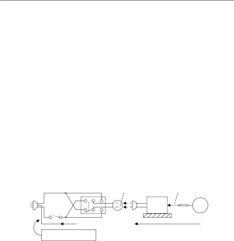
2.Hot Check ...Use the circuit shown below to perform the hot check test.
1.Keep switch S1 open and connect the receiver to the measuring circuit. Immediately after connection, and with the switching devices of the receiver in their operating positions, measure the leakage current for both positions of switch S2.
2.Close switch S1, energizing the receiver. Immediately after closing switch S1, and with the switching devices of the receiver in their operating positions, measure the leakage current for both positions of switch S2. Repeat the current measurements of items 1 and 2 after the receiver has reached thermal stabilization. The leakage current must not exceed 0.5 milliampere (mA).
Version 3.0
|
OPEN |
TOUCH ALL |
|
EXPOSED |
|
|
GROUND |
METAL PARTS |
|
RECEIVER |
|
|
S2 |
|
|
L |
AC MA |
|
|
|
|
N |
METER |
S1 |
|
|
|
|
|
|
SUPPLY CONNECTOR GROUND |
INSULATED TABLE |
|
|
GWG - Green Wire Ground
(Earth Ground)
Page 6
MODELS: WD-73640 / WD-73740 / WD-73840 / WD-73C11 / WD-73CA1 /
WD-82740 / WD-82840 / WD-82CB1 / WD-92840
DISASSEMBLY & PARTS REPLACEMENT
BACK COVER REMOVAL
C
Version 3.0
C B


 A
A
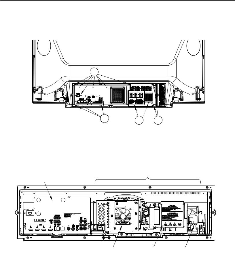
Back Cover Removal
1.Remove screws (A) and remove the Lamp Cover.
2.Remove screws (B) from behind the Lamp Cover.
3.Remove Screws (C).
4.Remove the back cover from the TV.
ASSEMBLY LOCATIONS
OPTICAL ENGINE ASSEMBLY
CHASSIS |
|
|
DMD FAN |
LAMP |
PWB-BALLAST |
Page 7
MODELS: WD-73640 / WD-73740 / WD-73840 / WD-73C11 / WD-73CA1 /
WD-82740 / WD-82840 / WD-82CB1 / WD-92840
CHASSIS - REMOVAL & DISASSEMBLY
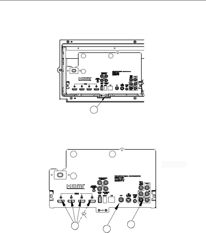
Chassis Removal
1.Remove screws (A).
2.Slide the chassis back and disconnect all cables.
3.Remove the chassis from the cabinet.
A |
Rear Terminal Cover Removal (To Replace PWB-MAIN)
1.Remove nut (A) from the ANT input.
2.Remove screws (B) and (C).
3.Disconnect the connectors to the PWB-SOUND (V45++).
4.Remove the Terminal Cover from the chassis.
PWB-SOUND CONNECTORS (ON REAR)
V45++ Only
|
V45++ Only |
|
C |
B |
|
A |
||
|
Version 3.0
Page 8
MODELS: WD-73640 / WD-73740 / WD-73840 / WD-73C11 / WD-73CA1 /
WD-82740 / WD-82840 / WD-82CB1 / WD-92840
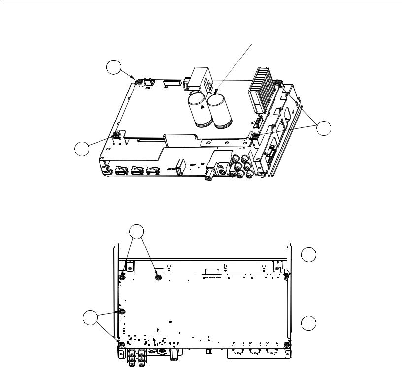
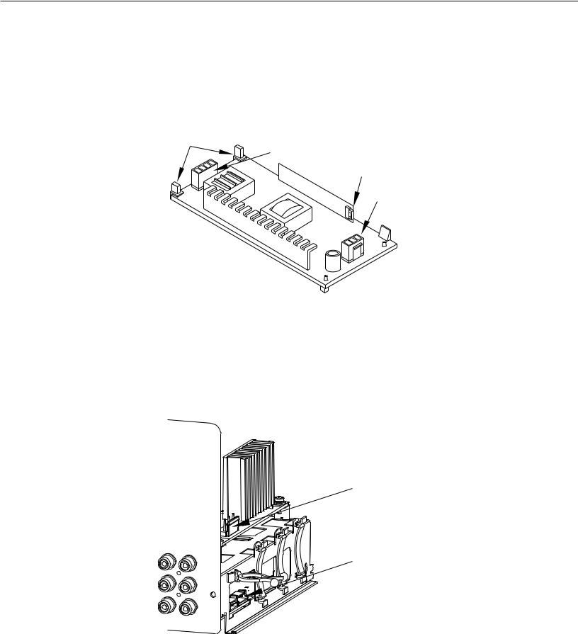
PWB-POWER Removal
1. |
Disconnect all cables from the PWB-POWER. |
|
|
2. |
Remove screws (A). |
|
|
3. |
Pinch the Retainer to release the PWB. |
|
|
Retainer |
|||
4. |
Lift the PWB-POWER from the chassis. |
||
|
|
(Pinch) |
A
A
PWB-MAIN Removal
1.Disconnect all cables to PWB-MAIN.
2.Remove screws (A) from the bottom of the PWB-MAIN.
3.Lift the PWB-MAIN from the chassis.
A
A
A


 A
A
 A
A
Version 3.0
After PWB-MAIN Replacement
See Data Transfer in Service Procedures section.
1.V45C, V45 & V45CA: Perform “Restore Engine Data From Backup.”
2.V45+, V45++ & V45CB: Perform “Restore Engine Data From Backup” and “Restore Geometry Data From Backup.”
V45+, V45++, V45CB IMPORTANT REPLACEMENT NOTE: If the customer has subscribed to VUDU (Internet program provider), the customer must be instructed to contact VUDU to re-activate their account after the replacement PWB has been installed. The original PWB cannot be installed in another TV. It must be returned to Mitsubishi per policy.
Page 9
MODELS: WD-73640 / WD-73740 / WD-73840 / WD-73C11 / WD-73CA1 /
WD-82740 / WD-82840 / WD-82CB1 / WD-92840
PWB-BALLAST REMOVAL
Note: To remove the PWB-BALLAST, it is not necessary to remove the Engine or Lamp Cartridge.
1.Release the Latch to lift the PWB-BALLAST up from the mounting bracket.
2.Slide the PWB-BALLAST out of the Engine Assembly.
3.Disconnect the electrical locking connectors indicated.
4.To reinstall, first connect the connectors. Then slide the PWB under the Retaining Hooks. Then press the rear edge of the PWB down onto the guide pins to engage the latch.
Version 3.0
RETAINING |
|
HOOKS |
CJ4 (HV to Lamp) |
|
CJ3 (Lamp Control)
CJ1 (Lamp Power)
 LATCH
LATCH
OPTICAL ENGINE ASSEMBLY - REMOVAL & DISASSEMBLY
OPTICAL ENGINE ASSEMBLY REMOVAL
1.Disconnect the PL connector from the side of the PWB-POWER.
2.Disconnect the FB connector from the side of the PWB-MAIN.
3.Loosen the wiring harnesses from the looms.
PL (Lamp Power)
FB
(Lamp Control and Lamp Door Switch)
Page 10

MODELS: WD-73640 / WD-73740 / WD-73840 / WD-73C11 / WD-73CA1 /
WD-82740 / WD-82840 / WD-82CB1 / WD-92840
OPTICAL ENGINE ASSEMBLY REMOVAL (Continued)
1.Disconnect the PE and J12 connectors from the Engine.
2.Remove screws (A).
3.Slide the Engine Assembly back out of the cabinet.
Version 3.0
J12 (LVDS) |
|
|
PE |
A |
A |
(Engine Power) |
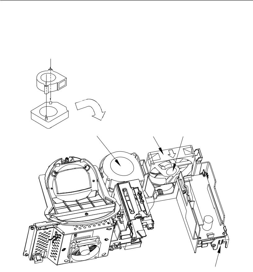
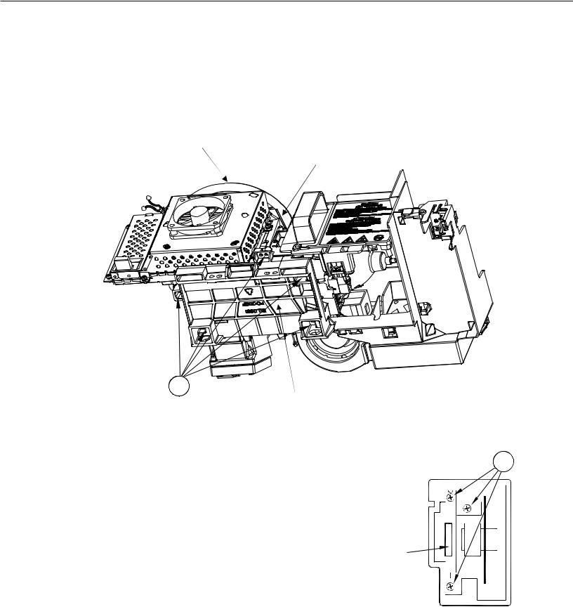
OPTICAL ENGINE ASSEMBLY - Disassembly
1.Loosen screw (A) to remove the Lamp Cartridge.
2.Remove screws (B) and the lamp top cover.
3.Remove screws (C) and the Engine Plate
4.Disconnect the Exhaust and Sirocco Fan Connectors (J4 and J8) from the back of the Engine and loosen the wiring harnesses from the looms.
5.Release the Latches to remove the Fan Holder.
C |
ENGINE PLATE |
LATCH
FAN HOLDER
B |
LATCH |
J8
(Sirocco Fan)


J4
(Exhaust Fan)
C A
Page 11
MODELS: WD-73640 / WD-73740 / WD-73840 / WD-73C11 / WD-73CA1 /
WD-82740 / WD-82840 / WD-82CB1 / WD-92840
Duct Interior Components
Duct Interior Components are shown below.
Notes:
When replacing the Optical Engine, transfer all Duct and Duct Interior Components from the old Engine to the new Engine.
The Exhaust Fan must be installed so the Label is facing inside the Duct.
The Sirocco Fan must be installed so the Label is facing up with the Flanges aligned onto the Guide Pins.
Sirocco Fan Flanges
Align Onto Guide Pins
Version 3.0
SIROCCO FAN |
|
(Label Facing In) |
(Label Facing Up) |
EXHAUST FAN |
PWB-LAMP DOOR SW
Page 12
MODELS: WD-73640 / WD-73740 / WD-73840 / WD-73C11 / WD-73CA1 /
WD-82740 / WD-82840 / WD-82CB1 / WD-92840
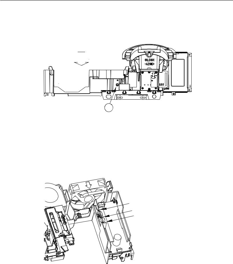
Lower Duct Removal
1.Remove the Lamp Cartridge, Top Cover, Exhaust Fan and Sirocco Fan.
2.Disconnect the HV Lamp Wiring from the Ballast and loosen it from the guides.
3.Remove screw (A) on the rear of the lower duct.
4.Carefully remove the Lower Duct from the Engine.
LOWER DUCT
A
OPTICAL ENGINE REPLACEMENT
1.Install Lower Duct and components on the new Engine.
2.Connect the HV Lamp Wiring to the Ballast and dress the wiring through the guides as shown.
3.Remove the Protective Lens Cover from the face of the Lens and place it on the old Engine for return.
4.Install the Engine Assembly in the cabinet.
5.Perform the following procedures as described in the Data Transfer section of the Service Procedures:
“Restore Index Delay”
“Save Engine and Geometry Setting to Backup”
6.As necessary, perform the Horizontal and Vertical Centering Adjustment and Manual Geometry Alignment as described in the Service Adjustments section of the Service Procedures.
HV LAMP WIRING
Dress Through Guides as Shown
Add VINAL CLAMP at center Guide.
Version 3.0
Page 13
MODELS: WD-73640 / WD-73740 / WD-73840 / WD-73C11 / WD-73CA1 /
WD-82740 / WD-82840 / WD-82CB1 / WD-92840
PROJECTION LENS REPLACEMENT
CAUTION: Any dust or fingerprints in the optics can cause abnormalities in the picture. This procedure should be performed in a dust free environment.
Wear lint free cotton or rubber gloves while performing this procedure.
1.Remove Optical Engine Assembly.
2.Remove screw (A) and remove the Lens Collar.
3.Remove screws (B).
4.Lift out the Projection Lens.
5.Install the replacement lens so the key is oriented towards the top as shown.
A |
LENS |
COLLAR |
Version 3.0
B |
|
|
|
|
|
B |
KEY |
||
|
|
|
|
|
|
|
|
|
|
|
|
|
|
|
|
|
|
|
|
|
|
|
|
|
|
|
|
|
|
LENS
B B
Page 14
MODELS: WD-73640 / WD-73740 / WD-73840 / WD-73C11 / WD-73CA1 /
WD-82740 / WD-82840 / WD-82CB1 / WD-92840
COLOR WHEEL REPLACEMENT
CAUTION: This procedure should be performed in a dust free environment.
Any dust entering into the optical compartment can cause abnormalities in the picture.
1.Remove the Optical Engine Assembly.
2.Remove the Lens Collar and cover the projection lens to protect it from scratches. See previous page.
3.Disconnect the 2 connectors, J6 & J7, from the front side of the Light Engine. Note the orientation of the ribbon cable for re-assembly (Silver Contacts towards the Lens).
4.Access the optical compartment by removing screws (A) and the Engine Base from the bottom of the Optical Engine
LENS COLLAR |
J6 & J7 |
|
(Opposite Side of Formatter PWB) |
A
|
ENGINE BASE |
|
|
|
|
5. |
Remove the 3 screws (B) from the Color Wheel Assembly. |
|
|
|
|
6. |
Use the metal Handle to lift the Color Wheel from the compartment. |
|
B |
||
7. |
For installation, reverse the procedure above. |
|
|||
|
CAUTION: Avoid touching or scratching the Color Wheel. |
|
|
|
|
8. |
After re-assembly, perform the Index Delay Adjustment described in the |
|
|
|
|
|
|
|
|||
|
Service Adjustments section. |
|
|
|
|
IMPORTANT: If part return is required, prevent damage by packing the color wheel the same way the replacement part was sent to you.
HANDLE
Version 3.0
Page 15
MODELS: WD-73640 / WD-73740 / WD-73840 / WD-73C11 / WD-73CA1 /
WD-82740 / WD-82840 / WD-82CB1 / WD-92840
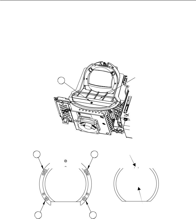
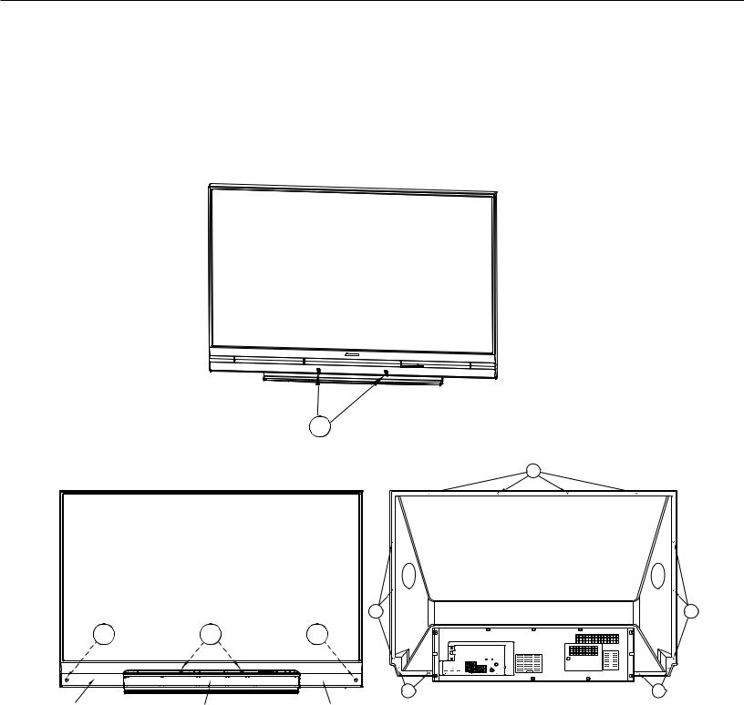
SCREEN REPLACEMENT 73” Models
Screen Assembly Removal and Replacement
1.V45C, V45, V45+ - Remove the Screw Caps to access screws (A).
2.V45++ - Remove the ORNAMENT LEFT & RIGHT first by pinching up and pulling away from the bottom. Then remove the ORNAMENT CENTER using the same method.
3.Remove screws (A).
4.Remove screws (B) around the rear edge of the screen bezel.
5.During re-assembly replace screws in their original locations.
V45C,V45, V45+ (73”)
Version 3.0
|
|
A |
|
|
|
|
B |
|
V45++ (73”) |
|
Number and Location of |
|
|
|
|
|
|
|
Screws Varies by Model |
|
|
|
73 INCH |
|
|
B |
B |
A |
A |
A |
|
|
|
B |
B |
ORNAMENT LEFT |
ORNAMENT |
ORNAMENT RIGHT |
|
|
CENTER |
|
|
|
(Speaker Cover) |
|
|
Page 16
MODELS: WD-73640 / WD-73740 / WD-73840 / WD-73C11 / WD-73CA1 /
WD-82740 / WD-82840 / WD-82CB1 / WD-92840
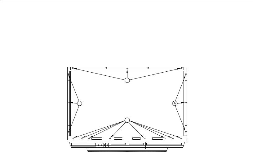
SCREEN REPLACEMENT 73” Models (continued)
Screen Removal From the Bezel-Front
1)Remove screws (A) and remove the top, bottom and side rails. NOTE: The number and location of screws vary by model.
2)Lift the Fresnel Lens and Lenticular screen from the Bezel-Front.
3)During re-assembly replace screws in their original locations.
|
A |
A |
73 INCH |
|
(Rear View) |
|
A |
Example Diagrams. The number and location of screws varies by model.
Version 3.0
Page 17
Loading...