


Mitsubishi PUHY-400YMF-C, 500YMF-C, PUHY-P400YMF-C, P500YMF-C, PUHY-600YSMF-C Service Manual
...Service Handbook PUHY-400YMF-C, 500YMF-C
PUHY-P400YMF-C, P500YMF-C
PUHY-600YSMF-C, 650YSMF-C, 700YSMF-C, 750YSMF-C
PUHY-P600YSMF-C, P650YSMF-C, P700YSMF-C, P750YSMF-C
HEAD OFFICE MITSUBISHI DENKI BLDG. MARUNOUCHI TOKYO 100-0005 TELEX J24532 CABLE MELCO TOKYO
C-P600·P650·P700·P750YSMF-C/PUHY-600·650·700·750YSMF-C/PUHY-P400·P500YMF-C/PUHY-400·500YMF-PUHY Handbook Service
AIR CONDITIONERS CITY MULTI
Models PUHY-400YMF-C, 500YMF-C PUHY-P400YMF-C, P500YMF-C
PUHY-600YSMF-C, 650YSMF-C, 700YSMF-C, 750YSMF-C
PUHY-P600YSMF-C, P650YSMF-C, P700YSMF-C, P750YSMF-C
Service Handbook
New publication effective Jan 2003
Issued in May 2003 MEE02K140 Specifications subject to change without notice. Printed in Japan
Contents
1 |
PRECAUTIONS FOR DEVICES |
|
|
|
THAT USE R407C REFRIGERANT ......................................... |
1 |
|
|
[1] Storage of Piping Material ............................................. |
2 |
|
|
[2] |
Piping Machining ........................................................... |
3 |
|
[3] |
Brazing ........................................................................... |
4 |
|
[4] |
Airtightness Test............................................................. |
5 |
|
[5] |
Vacuuming ..................................................................... |
5 |
|
[6] |
Charging of Refrigerant ................................................. |
6 |
|
[7] |
Dryer .............................................................................. |
6 |
2 |
COMPONENT OF EQUIPMENT ............................................. |
7 |
|
|
[1] |
Appearance of Components .......................................... |
7 |
|
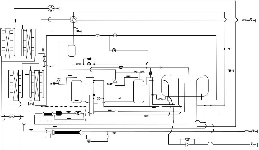
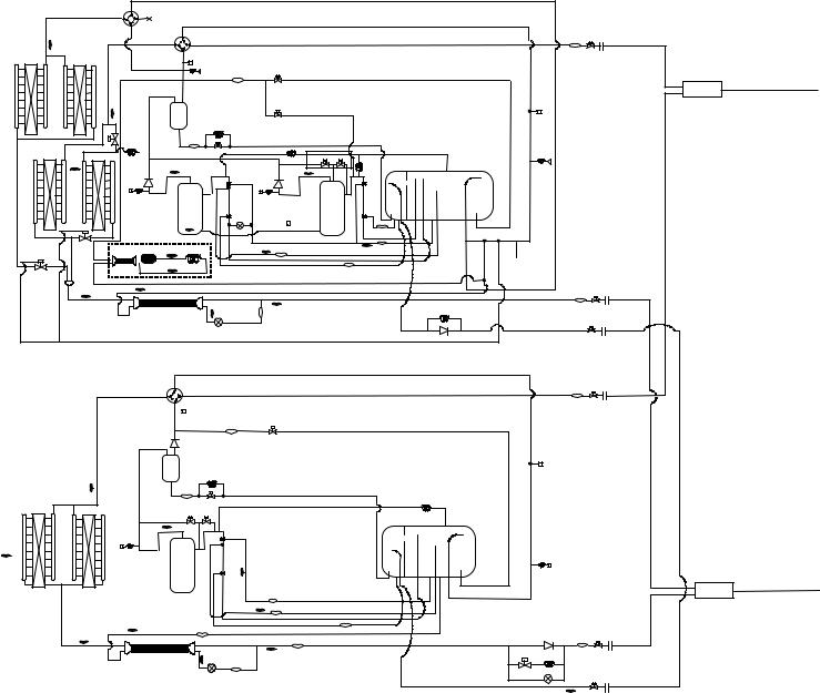
[2] Refrigerant Circuit Diagram and Thermal Sensor ........ |
18 |
|
|
[3] |
Electrical Wiring Diagram ............................................. |
22 |
|
[4] |
Standard Operation Data ............................................. |
24 |
|
[5] Function of Dip SW and Rotary SW ............................ |
36 |
|
3 |
TEST RUN ............................................................................. |
42 |
|
|
[1] |
Before Test Run ........................................................... |
42 |
|
[2] |
Test Run Method .......................................................... |
48 |
4 |
GROUPING REGISTRATION OF INDOOR UNITS WITH |
|
|
|
M-NETREMOTE CONTROLLER ........................................... |
49 |
|
5 |
CONTROL.............................................................................. |
55 |
|
|
[1] Control of Outdoor Unit ................................................ |
55 |
|
|
[2] |
Operation Flow Chart ................................................. |
106 |
|
[3] List of Major Component Functions ........................... |
111 |
|
|
[4] |
Resistance of Temperature Sensor ............................ |
115 |
6 |
REFRIGERANT AMOUNT ADJUSTMENT ......................... |
116 |
|
|
[1] Operating Characteristics and Refrigerant Amount ... |
116 |
|
|
[2] Adjustment and Judgement of Refrigerant Amount ... |
116 |
|
|
[3] Refrigerant Volume Adjustment Mode Operation....... |
119 |
|
7 |
TROUBLESHOOTING ......................................................... |
125 |
|
|
[1] |
Principal Parts ............................................................ |
125 |
|
[2] Self-diagnosis and Countermeasures Depending |
|
|
|
|
on the Check Code Displayed ................................... |
153 |
|
[3] |
LED Monitor Display .................................................. |
175 |
8 |
PREPARATION, REPAIRS AND REFRIGERANT |
|
|
|
REFILLING WHEN REPAIRING LEAKS .............................. |
199 |
|
|
[1] Location of leaks: Extension piping or indoor units |
|
|
|
|
(when cooling) ........................................................... |
199 |
|
[2] Location of leaks: Outdoor unit (Cooling mode) ......... |
200 |
|
|
[3] Location of leaks: Extension piping or indoor units |
|
|
|
|
(Heating mode) .......................................................... |
200 |
|
[4] Location of leaks: Outdoor unit (when heating).......... |
201 |
|
9 |
CHECK THE COMPOSITION OF THE REFRIGERANT...... |
202 |
|

Safety precautions
Before installation and electric work
 Before installing the unit, make sure you read all the “Safety precautions”.
 The “Saftey precautions” provide very important points regarding safety. Make sure you follow them.
 This equipment may not be applicable to EN61000-3-2: 1995 and EN61000-3-3: 1995.
 This equipment may have an adverse effect on equipment on the same electrical supply system.
 Please report to or take consent by the supply authority before connection to the system.
Symbols used in the text
 Warning:
Describes precautions thatshould be observed to prevent danger of injury or deathto the user.
 Caution:
Describes precautionsthatshould be observed to
preventdamage to the unit.
Symbols used in the illustrations
 : Indicates an action that must be avoided.
 : Indicates important instructions must be followed.
 : Indicates a part which must be grounded.
 : Beware of electric shock (This symbol is displayed on the main unit label.) <Color: Yellow>
 Warning:
Carefully read the labels affixed to the main unit.
 Warning:
•Use the specified cables for wiring.Make the connections securely so that the outside force of the cable is not applied to the terminals.
-Inadequate connection and fastening may generate heat and cause a fire.
•Have all electric work done by a licensedelectrician according to “Electric Facility Engineering Standard”and
“Interior Wire Regulations”and the instructions given in this manual and always use a dedicated circuit.
-If the power source capacity is inadequate or electric work is performed improperly, electric shock and fire may result.
•Securely install the cover of control box and the panel.
-If the cover and panel are not installed properly, dust or water may enter the outdoor unit and fire or electric shock may result.
•After completing service work, make sure that refrigerant gas is not leaking.
-If the refrigerant gas leaks and is exposed to a fan heater, stove, oven, or other heat source, it may generate noxious gases.
•Do not reconstruct or change the settings of the protection devices.
-If the pressure switch, thermal switch, or other protection device is shorted and operated forcibly, or parts other than those specified by Mitsubishi Electric are used, fire or explosion may result.
¡ PRECAUTIONS FOR DEVICES THAT USE R407C REFRIGERANT
 Caution
Do not use the existing refrigerant piping.
•The old refrigerant and refrigerator oil in the existing piping contains a large amount of chlorine which may cause the refrigerator oil of the new unit to deteriorate.
Use refrigerant piping made of phosphorus deoxidized copper and copper alloy seamless pipes and tubes”. In addition, be sure that the inner and outer surfaces of the pipes are clean and free of hazardous sulphur, oxides, dust/dirt, shaving particles, oils, moisture, or any other contaminant.
•Contaminants on the inside of the refrigerant piping may cause the refrigerant residual oil to deteriorate.
Store the piping to be used during installation indoors and keep both ends of the piping sealed until just before brazing. (Store elbows and other joints in a plastic bag.)
•If dust, dirt, or water enters the refrigerant cycle, deterioration of the oil and compressor trouble may result.
Use ester oil, ether oil or alkylbenzene (small
amount) as the refrigerator oil to coat flares and
flange connections.
•The refrigerator oil will degrade if it is mixed with a large amount of mineral oil.
Use liquid refrigerant to seal the system.
•If gas refrigerant is used to seal the system, the composition of the refrigerant in the cylinder will change and performance may drop.
Do not use a refrigerant other than that specified.
•If another refrigerant is used, the chlorine in the refrigerant may cause the refrigerator oil to deteriorate.
Use a vacuum pump with a reverse flow check valve.
•The vacuum pump oil may flow back into the refrigerant cycle and cause the refrigerator oil to deteriorate.
Do not use the following tools that have been used with conventional refrigerants.
(Gauge manifold, charge hose, gas leak detector, reverse flow check valve, refrigerant charge base, vacuum gauge, refrigerant recovery equipment)
•If the conventional refrigerant and refrigerator oil are mixed in the R407C, the refrigerant may deteriorated.
•If water is mixed in the R407C, the refrigerator oil may deteriorate.
•Since R407C does not contain any chlorine, gas leak detectors for conventional refrigerants will not react to it.
Do not use a charging cylinder.
•Using a charging cylinder may cause the refrigerant to deteriorate.
Be especially careful when managing tools.
•If dust, dirt, or water that gets in the refrigerant cycle, may cause the refrigerant to deteriorate.
If the refrigerant leaks, recover the refrigerant in the refrigerant cycle, then recharge the cycle with the specified amount of the liquid refrigerant indicated on the air conditioner.
•Since R407C is a nonazeotropic refrigerant, if additionally charged when the refrigerant leaked, the composition of the refrigerant in the refrigerant cycle will change and result in a drop in performance or abnormal stopping.
-1-
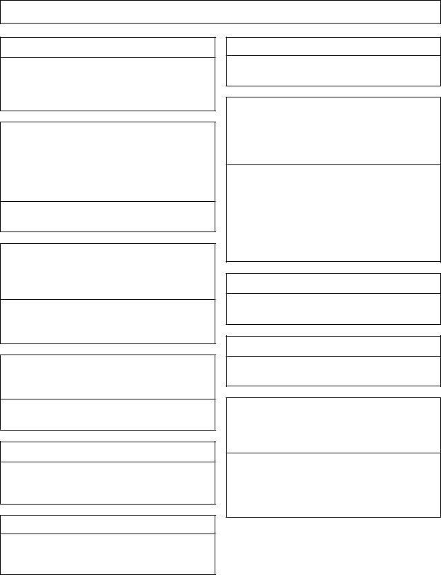
[1] Storage of Piping Material
(1) Storage location
Store the pipes to be used indoors. (Warehouse at site or owner’s warehouse)
Storing them outdoors may cause dirt, waste, or water to infiltrate.
(2) Pipe sealing before storage
Both ends of the pipes should be sealed until immediately before brazing.
Wrap elbows and T’s in plastic bags for storage.
*The new refrigerator oil is 10 times more hygroscopic than the conventional refrigerator oil (such as Suniso). Water infiltration in the refrigerant circuit may deteriorate the oil or cause a compressor failure. Piping materials must be stored with more care than with the conventional refrigerant pipes.
-2-
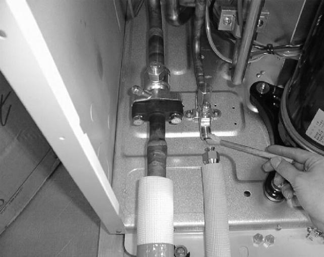
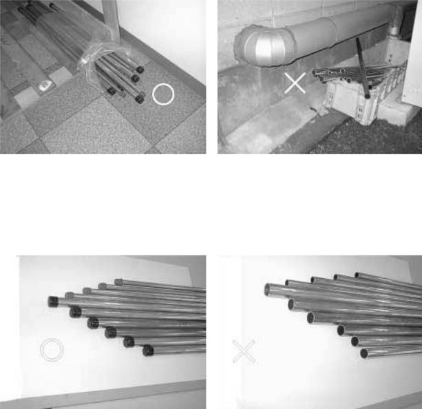
[2] Piping Machining
Use ester oil, ether oil or alkylbenzene (small amount) as the refrigerator oil to coat flares and flange connections.
Use only the necessary minimum quantity of oil !
Reason:
1. The refrigerator oil used for the equipment is highly hygroscopic and may introduce water inside.
Notes:
•Introducing a great quantity of mineral oil into the refrigerant circuit may also cause a compressor failure.
•Do not use oils other than ester oil, ether oil or alkylbenzene
-3-
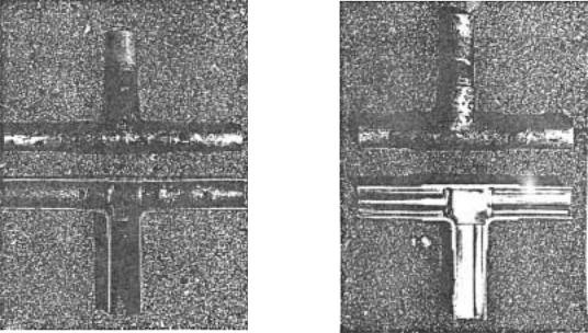
[3] Brazing
No changes from the conventional method, but special care is required so that foreign matter (ie. oxide scale, water, dirt, etc.) does not enter the refrigerant circuit.
Example : Inner state of brazed section
When non-oxide brazing was not used |
When non-oxide brazing was used |
Items to be strictly observed :
1.Do not conduct refrigerant piping work outdoors on a rainy day.
2.Apply non-oxide brazing.
3.Use a brazing material (Bcup-3) which requires no flux when brazing between copper pipes or between a copper pipe and copper coupling.
4.If installed refrigerant pipes are not immediately connected to the equipment, then braze and seal both ends of them.
Reasons :
1.The new refrigerant oil is 10 times more hygroscopic than the conventional oil. The probability of a machine failure if water infiltrates is higher than with conventional refrigerant oil.
2.A flux generally contains chlorine. A residual flux in the refrigerant circuit may generate sludge.
Note :
•Commercially available antioxidants may have adverse effects on the equipment due to its residue, etc. When applying non-oxide brazing, use oxygen free nitrogen (OFN).
-4-
[4] Airtightness Test
No changes from the conventional method. Note that a refrigerant leakage detector for R22 cannot detect R407C
leakage.
Halide torch |
R22 leakage detector |
Items to be strictly observed :
1.Pressurize the equipment with nitrogen up to the design pressure and then judge the equipment’s airtightness, taking temperature variations into account.
2.When investigating leakage locations using a refrigerant, be sure to use R407C.
3.Ensure that R407C is in a liquid state when charging.
Reasons :
1.Use of oxygen as the pressurized gas may cause an explosion.
2.Charging with R407C gas will lead the composition of the remaining refrigerant in the cylinder to change and this refrigerant can then not be used.
Note :
•A leakage detector for R407C is sold commercially and it should be purchased.
[5]Vacuuming
1.Vacuum pump with check valve
A vacuum pump with a check valve is required to prevent the vacuum pump oil from flowing back into the refrigerant circuit when the vacuum pump power is turned off (power failure).
It is also possible to attach a check valve to the actual vacuum pump afterwards.
2.Standard degree of vacuum for the vacuum pump
Use a pump which reaches 0.5 Torr (500 MICRON) or below after 5 minutes of operation.
In addition, be sure to use a vacuum pump that has been properly maintained and oiled using the specified oil. If the vacuum pump is not properly maintained, the degree of vacuum may be too low.
3.Required accuracy of the vacuum gauge
Use a vacuum gauge that can measure up to 5 Torr. Do not use a general gauge manifold since it cannot measure a vacuum of 5 Torr.
4.Evacuating time
•Evacuate the equipment for 1 hour after –755 mmHg (5 Torr) has been reached.
•After envacuating, leave the equipment for 1 hour and make sure that the vacuum is not lost.
5.Operating procedure when the vacuum pump is stopped
In order to prevent a backflow of the vacuum pump oil, open the relief valve on the vacuum pump side or loosen the charge hose to drawn in air before stopping operation.
The same operating procedure should be used when using a vacuum pump with a check valve.
-5-
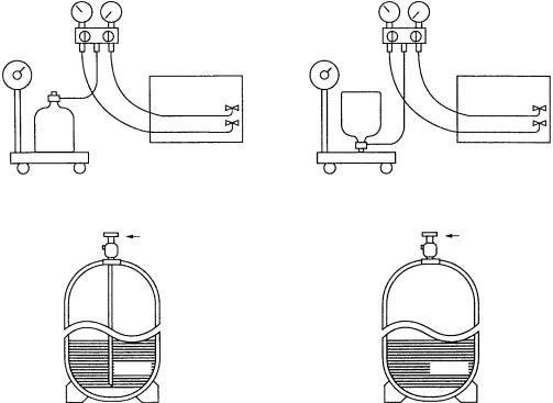
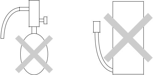
[6] Charging of Refrigerant
R407C must be in a liquid state when charging, because it is a non-azeotropic refrigerant.
For a cylinder with a syphon attached For a cylinder without a syphon attached
|
Cylin- |
Cylin- |
der |
|
|
der |
|
Cylinder color identification |
R407C-Gray |
Charged with liquid refrigerant |
|
R410A-Pink |
Valve |
Valve |
|
|
|
|
Liquid |
Liquid |
Reasons :
1.R407C is a mixture of 3 refrigerants, each with a different evaporation temperature. Therefore, if the equipment is charged with R407C gas, then the refrigerant whose evaporation temperature is closest to the outside temperature is charged first while the rest of refrigerants remain in the cylinder.
Note :
•In the case of a cylinder with a syphon, liquid R407C is charged without turning the cylinder up side down. Check the type of cylinder before charging.
[7]Dryer
1.Replace the dryer when the refrigerant circuit is opened (Ex. Change the compressor, full gas leakage). Be sure to replace the dryer with a CITY MULTI Series Y (For use with R407C).
If any other product is used, the unit will be damaged.
2.Opening the refrigerant circuit after changing to a new dryer is less than 1 hour. The replacement of the dryer should be the last operation performed.
-6-
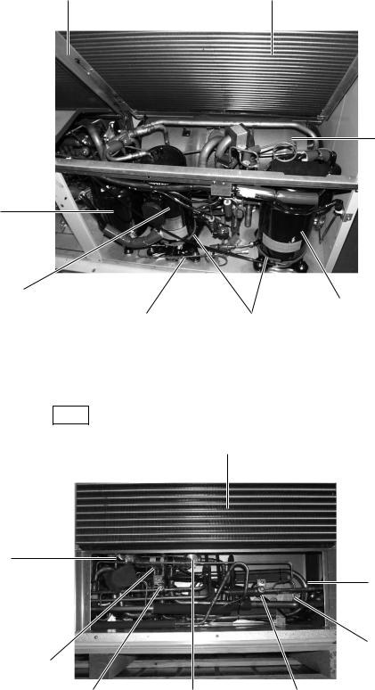
[1] Appearance of Components
1Variable capacity unit
Ambient temperature Sensor |
Heat Exchanger |
Accumlator
Oil Separator
Variable Capacity |
|
|
Compressor |
Constant Capacity Compressor |
|
(No. 1 Compressor) |
||
(No. 2 Compressor) |
||
Oil Equalization Pipe |
||
Crank Case Heater |
Rear
Heat Exchanger
Four-way Valve
(21S4a)
Sub-cool Coil
Heat Exchanger of CS circuit (PUHY-P-YMF-C only)
Four-way Valve (21S4b)
Solenoid Valve |
Solenoid Valve |
Solenoid Valve |
(SV8) |
(SV7) |
(SV5b) |
(PUHY-P-YMF-C only) |
(PUHY-P-YMF-C only) |
|
-7-
2 Constant capacity unit
Ambient temperature Sensor
Four-way valve
Service check-point  (right; high pressure,
left; low pressure)
Gas ball valve
Liquid ball valve
Constant capacity compressor (No. 3 compressor)
Solenoid valve (SV3, PUHN-P-YMF-C only) Solenoid valve (SV2, PUHN-P-YMF-C only)
Heat exchanger
Accumlator
Controller box
Oil balance pipe
Crank Case Heater
Rear
Heat Exchanger
Accumlator |
Sub-cool Coil |
-8-
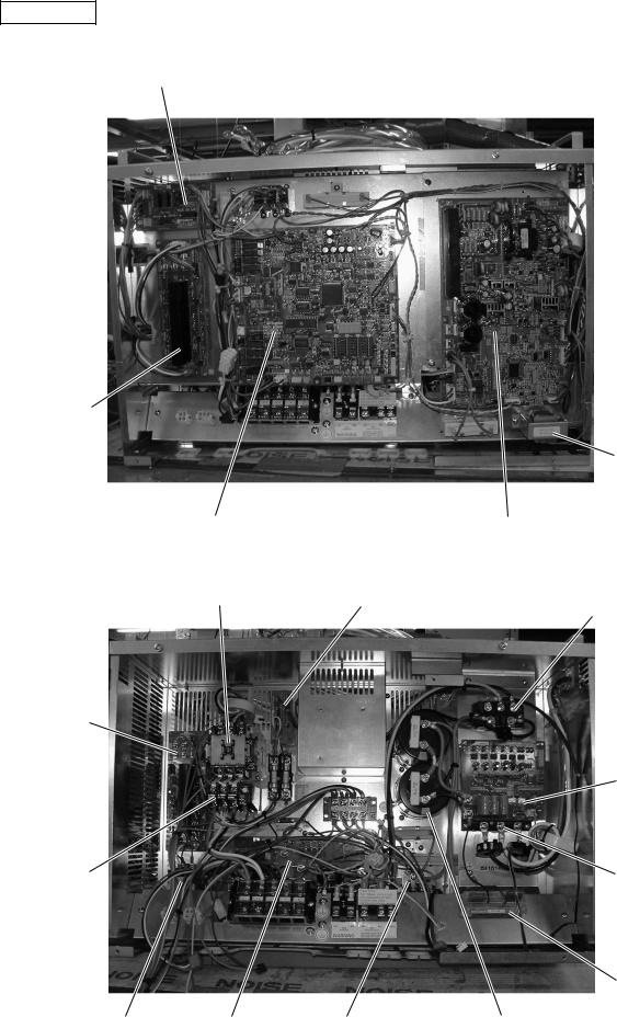
Controller Box
RELAY board
FANCON board (for MF3)
Choke coil (L2)
MAIN board |
INV board |
Magnetic contactor (52C2) |
SNB board |
|
Diode stack (DS) |
FANCON board (for MF2)
G/A board
Overload relay |
Inteligent Power |
(51C2) |
Module (IPM) |
Y-C board
Magnetic contactor |
Noise filter |
Magnetic contactor (52C1) |
Capacitor (C2, C3) |
(52F) |
(NF) |
|
(Smoothing capacitor) |
-9-
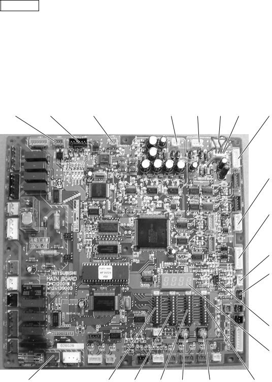
MAIN board
|
|
CNVCC4 |
|
|
|
|
|
Power source |
|
|
|
CNTR |
CNFC1 |
for control(5V) |
CNS1 |
CNS2 CN40 CN41 |
CNVCC3 |
|
|
|
|
|
Power Source |
|
|
|
|
|
for control |
|
|
|
|
|
1-2 30V |
|
|
|
|
|
1-3 30V |
|
|
|
|
|
4-6 12V |
|
|
|
|
|
5-6 5V |
|
|
|
|
|
CN51 |
|
|
|
|
|
Indication distance |
|
|
|
|
|
3-4 Compressor |
|
|
|
|
|
ON/OFF |
|
|
|
|
|
3-5Trouble |
|
|
|
|
|
CNRS3 |
|
|
|
|
|
Serial transmission to |
|
|
|
|
|
INV board |
|
|
|
|
|
CN3D |
|
|
|
|
|
CN3S |
CN3N
LD1
Service LED
CN20 SW4 SW3 SW2 SWU2 SWU1 SW1
Power supply
3 L1
1 N
-10-
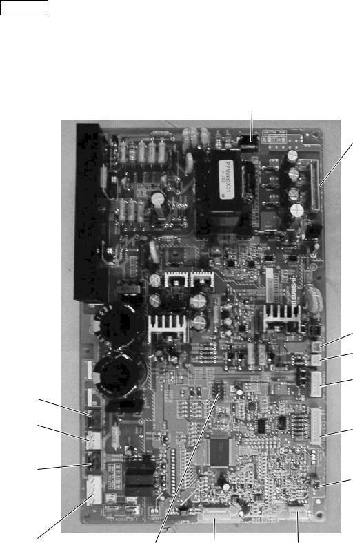
INV board
CNVDC
1 - 4
DC-560V
CN15V2 Power supply for IPM control
|
CNVCC4 |
|
|
Power supply (5V) |
|
|
CNL2 |
|
|
Choke coil |
|
|
CNVCC2 |
|
|
Power supply |
|
CNR |
1-2 30V, 1-3 30V |
|
4-6 12V, 5-6 5V |
||
|
||
CN52C |
CNDR2 |
|
Control for |
Out put to |
|
52C |
G/A board |
|
CNFAN |
CNTH |
|
Control |
||
for MF1 |
|
CNAC2 |
|
|
|
|
Power Source |
SW1 |
CNRS2 |
CNACCT |
|
1 L2 |
||||
|
Serial transmission |
|
||
3 N |
|
|
||
|
to MAIN board |
|
||
5 G |
|
|
|
-11-
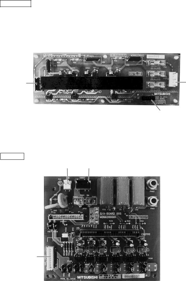
FANCON board
CNFAN |
CNPOW |
CNFC2
G/A board
CNE CNDC1
CN15V1 
 CNIPM1
CNDR1
-12-
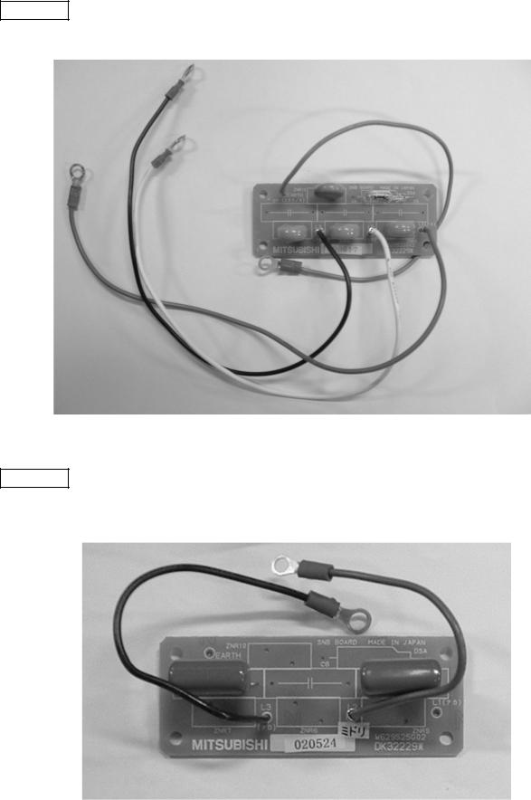
SNB board
Y-C board
-13-
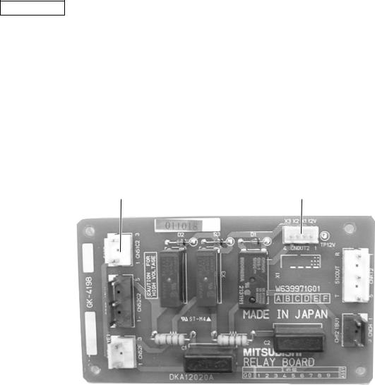
RELAY board
CN51C2 |
CNOUT2 |
 CNRT2
CNRT2
CN52C2 
 CNCH
CNCH
CN52F 
-14-
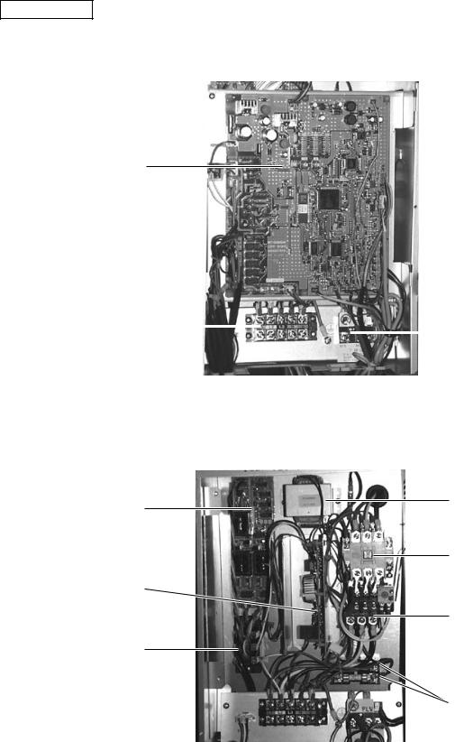
• Constant capacity unit
Controller Box
Control board
Terminal block TB1 |
|
|
|
Terminal block TB3 |
|
|
|||
powersource |
|
transmission |
||
Transformer
FANCON board
Magnetic contactor (52C)
Noise Filter (NF)
Thermal overload relay (51C)
Thyristor module (SCRM)
Fuses (F1, F2)
-15-
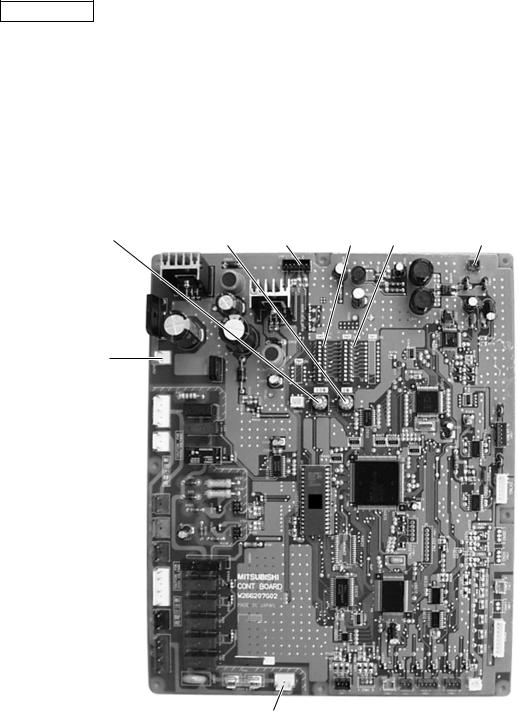
CONT board
|
|
|
|
CNS1 |
|
|
|
|
M-NET |
SWU2 |
SWU1 |
CNFC1 |
SW3 SW2 |
transmission |
CNTR
CN20
Power supply
1 N
3 L1
-16-

FANCON board
CNV |
CNW |
CNU |
CNFC2 |
-17-
|
|
|
|
|
|
|
|
There are SV22,SV32 only for PUHY-500YMF-C. |
|
21S4b |
|
|
|
|
|
|
|
T10a |
21S4a |
|
|
|
|
|
BV1 |
|
HEX1b |
HEX2b |
|
|
|
|
|
|
ST1 |
|
|
CJ1 |
|
|
|
|
|
|
|
|
63HS |
SV4 |
|
|
|
|
|
|
|
|
ST5 |
|
|
|
|
CJ2 |
TH6 |
|
|
SV6 |
|
|
|
||
|
|
|
|
|
|
|||
|
|
|
|
|
|
|
|
|
|
|
O/S |
|
|
|
|
|
|
|
|
CP1 |
|
|
|
|
|
|
|
|
ST6 |
|
|
|
|
|
|
|
|
SV1 |
|
|
|
|
|
|
|
T10b |
|
|
SV22 |
SV32 |
|
|
|
|
|
|
CP3a |
|
|
|||
|
|
|
|
|
|
|
|
|
-18- |
|
TH11 |
|
TH12 |
|
CP3b |
|
|
|
|
|
|
|
|
|||
|
CV1 |
|
CV2 |
|
|
|
|
|
|
|
|
|
|
|
|
||
|
63H1 |
|
63H2 |
|
|
|
SA |
MA |
|
|
No.1 |
|
|
No.2 |
|
|
|
|
|
Comp. |
SLEV |
CJ3 |
Comp. |
|
|
|
HEX1a |
HEX2a |
CP4 |
|
|
|
|
ST9 |
|
|
|
|
|
|
|
|||
|
|
|
|
|
|
|
|
|
|
|
|
TH4 |
ST4 |
|
TH3 |
ST3 |
TH2 |
|
|
|
|
|
|
|
|
|
SV5b |
|
|
|
|
|
|
|
CP2 |
|
TH8 |
|
|
|
|
ST8 |
|
|
|
TH5 |
|
|
|
|
|
|
BV2 |
|
SCC |
TH9 |
ST7 |
|
|
|
|
ST2 |
|
TH7 |
|
|
|
CP5 |
|||
|
|
|
|
|
|
|
|
BV3 |
|
|
LEV1 |
|
|
|
|
|
|
Sensor Thermal and Diagram Circit Refrigerant [2] C-500YMF 400,-PUHY
CV3
|
|
|
|
|
|
|
|
|
|
There are SV22,SV32 only for PUHY-P500YMF-C. |
|
|
|
|
21S4b |
|
|
|
|
|
|
|
|
|
|
|
|
21S4a |
|
|
|
|
|
|
BV1 |
|
|
TH10a |
|
|
|
|
|
|
|
|
|
|
HEXB1 |
HEXF1 |
|
|
CJ1 |
|
|
|
|
|
ST1 |
|
|
|
|
|
|
|
|
|
|||
|
|
|
|
|
|
|
|
|
|
|
|
|
|
|
|
|
63HS |
|
SV4 |
|
|
|
|
|
|
|
|
|
|
|
|
|
|
|
|
|
|
|
|
|
|
ST5 |
|
|
|
|
|
|
|
|
|
|
|
|
SV6 |
|
|
CJ2 |
|
|
|
|
|
|
|
|
|
|
|
|
|
|
|
|
TH10b |
O/S |
|
|
|
|
|
|
|
|
|
|
|
|
|
|
|
|
|
|
|
|
|
|
|
|
CP1 |
|
|
|
|
|
|
|
|
|
SV7 |
|
ST6 |
|
|
|
|
|
|
|
|
|
CP7 |
|
|
|
|
|
|
|
|
|
|
|
|
|
|
|
|
|
|
|
|
|
|
|
|
|
SV1 |
|
|
CP3a |
SV22 |
SV32 |
|
-19- |
|
TH6 |
HEXF2 |
TH11 |
|
|
|
|
|||
HEXB2 |
|
|
|
|
|
CP3b |
|
||||
|
|
CV2 |
TH12 |
|
|
||||||
|
|
CV1 |
|
|
|
63LS |
|
||||
|
|
|
|
|
|
|
|
|
|
||
|
|
|
|
|
|
|
|
|
|
MA |
|
|
|
|
63H1 |
Comp1 |
|
63H2 |
|
|
SA |
|
|
|
|
|
|
|
|
|
|
|
Comp2 |
|
|
|
|
|
|
TH10c |
SLEV |
CJ3 |
|
|
|
||
|
|
|
|
|
|
|
|
ST9 |
|
||
|
|
|
|
|
|
|
|
|
|
|
|
|
|
SV8 |
|
|
CP4 |
|
TH4 |
|
|
|
|
|
|
Drier |
TH9b |
CP2 |
|
ST4 |
|
TH3 ST3 |
|
||
|
|
|
|
|
|
||||||
|
|
|
|
TH2 |
|
|
|
|
|
|
|
|
SV5b |
|
|
|
|
|
|
|
|
ST8 |
|
|
|
|
|
|
|
|
|
|
|
|
|
|
|
TH5 |
TH8 |
|
|
|
|
|
|
BV2 |
|
|
|
|
|
|
TH9a |
ST7 |
TH7 |
|
|
CP5 |
ST2 |
|
|
|
|
|
|
|
BV3 |
||||
|
|
|
|
|
|
|
|
|
|
|
|
|
|
|
|
|
LEV1 |
|
|
|
CV3 |
|
|
|
|
|
|
|
|
|
|
|
|
|
|
C-500YMF P400,-PUHY
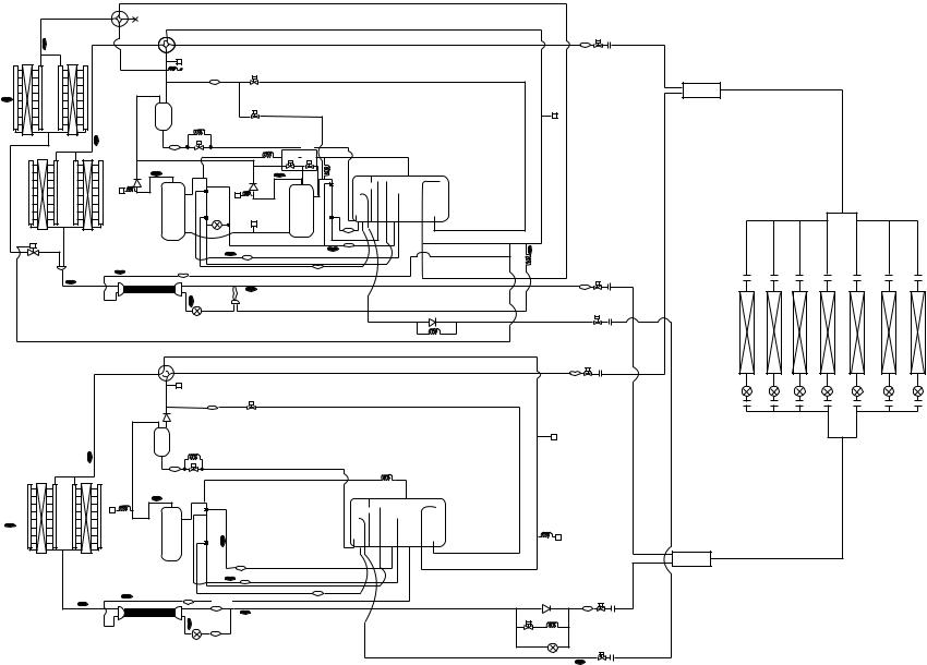
PUHY-400,500YMF-C |
|
|
|
|
|
|
|
|
|
|
|
There are SV22,SV32 only for PUHY-700, 750YSMF-C. |
-PUHY |
|
|
|
|
|
|
|
|
|
|
|
|
|
|||
|
|
|
|
|
|
|
|
|
|
|
|
|
||
|
21S4b |
|
|
|
|
|
|
|
|
|
|
|
600, |
|
|
TH10a |
21S4a |
|
|
|
|
|
|
|
|
BV1 |
|
||
|
|
|
|
|
|
|
|
|
|
|
||||
|
|
|
|
|
|
|
|
|
|
|
|
|
|
|
HEX1b |
HEX2b |
|
CJ1 |
|
|
|
|
|
|
|
|
ST1 |
|
650, |
|
|
|
|
|
|
|
|
|
|
|
||||
|
|
|
63HS |
|
|
SV4 |
|
|
|
|
|
|
Distributer (Gas) |
|
TH6 |
|
|
ST5 |
|
|
|
|
|
|
|
|
|
700, |
|
|
|
|
O/S |
|
|
SV6 |
|
|
|
|
CJ2 |
|
|
|
|
|
|
|
|
|
|
|
|
|
|
|
|||
|
|
|
|
|
|
|
|
|
|
|
|
|
|
|
|
|
|
CP1 |
|
|
|
|
|
|
|
|
|
|
-750YSMF |
|
|
63H1 |
ST6 |
|
|
|
|
|
SA |
|
|
|
|
|
|
|
TH10b |
|
|
|
|
|
|
|
|
|
|
|
|
|
|
|
SV1 |
|
|
CP3a |
SV22 |
SV32 |
|
|
|
|
|
|
|
|
CV1 |
TH11 |
|
CV2 |
|
|
|
CP3b |
|
|
|
|
|
|
|
|
|
TH12 |
|
|
|
|
|
|
|
|||
|
|
|
|
|
|
|
|
|
|
|
|
|||
|
|
|
|
|
|
|
|
|
|
MA |
|
|
|
|
|
|
|
Comp1 |
SLEV |
63H2 |
Comp2 |
|
|
|
|
Indoor unit |
C |
||
|
|
|
|
|
CJ3 |
|
|
|
|
|
|
|
||
|
|
|
|
|
|
|
|
|
|
|
|
|
||
HEX1a |
|
HEX2a |
CP4 |
|
|
|
|
|
ST9 |
|
|
|
|
|
|
|
|
TH4 |
|
ST4 |
|
TH3 |
ST3 |
TH2 |
|
|
|
||
|
|
|
|
|
|
|
|
|
||||||
SV5b |
|
TH8 |
ST10 |
|
|
|
|
|
|
CP2 |
|
|
|
|
|
|
|
|
|
|
ST8 |
|
|
|
|
|
|
||
|
TH5 |
|
|
|
|
|
|
|
|
BV2 |
|
|
||
|
|
|
|
|
|
|
|
|
|
|
|
|||
|
|
|
|
|
|
|
|
|
|
|
|
|
||
|
|
SCC |
|
ST7 |
TH7 |
|
|
|
|
|
ST2 |
|
|
|
|
|
TH9 |
|
|
|
|
|
|
|
|||||
-20- |
|
|
LEV1 |
|
|
|
|
|
CV3 |
|
BV3 |
|
|
|
|
|
|
|
|
|
|
|
|
|
|
||||
|
|
|
|
|
|
|
|
|
|
|
|
|||
|
|
|
|
|
|
|
|
|
CP5 |
|
|
|
|
|
PUHN-200,250YMF-C |
21S4 |
|
|
|
|
|
|
|
|
|
BV1 |
|
|
|
|
|
|
|
|
|
|
|
|
|
|
|
|||
|
|
|
CJ1 |
|
|
|
|
|
|
|
|
ST1 |
|
|
|
|
|
|
|
|
|
|
|
|
|
|
Oil balance |
|
|
|
|
|
ST5 |
SV4 |
|
|
|
|
|
|
|
|||
|
|
|
|
|
|
|
|
|
pipe |
|
||||
|
|
|
|
|
|
|
|
|
|
|
|
|||
|
|
|
|
|
|
|
|
|
|
|
|
|
|
|
|
|
|
CV1 |
|
|
|
|
|
|
|
|
|
|
|
|
|
|
O/S |
|
|
|
|
|
|
|
CJ2 |
|
|
|
|
|
|
CP1 |
|
|
|
|
|
|
|
|
|
|
|
|
TH10a |
|
ST6 |
|
|
|
|
|
|
|
|
|
|
|
|
|
|
|
|
|
|
|
|
CP3 |
|
|
|
|
|
|
|
|
SV1 |
|
|
|
|
|
|
|
|
|
|
|
|
|
|
|
|
|
|
|
|
|
|
|
|
|
|
|
|
|
TH11 |
|
|
|
|
|
|
|
|
|
|
|
TH6 |
|
63H |
Comp1 |
|
|
|
|
|
|
MA |
|
|
|
|
|
|
|
|
|
|
|
|
|
|
|
|
|||
|
|
|
|
|
|
|
|
SA |
|
|
|
|
|
|
|
|
|
|
TH3 |
|
|
|
|
|
|
|
|
||
|
|
|
|
|
|
|
|
|
63LS |
|
Distributer (Liquid) |
|
||
|
|
|
|
|
|
|
|
|
|
|
|
|
||
|
|
|
|
|
|
|
|
|
|
|
|
|
|
|
HEX1 |
|
HEX2 |
|
|
ST3 |
|
|
|
|
|
|
|
|
|
|
|
|
|
TH4 |
ST4 |
|
|
|
|
|
|
|
|
|
|
|
|
|
|
|
|
|
|
|
|
|
|
|
|
|
TH5 |
TH8 |
ST10 |
|
|
|
|
|
|
CV2 |
BV2 |
|
|
|
|
|
ST9 |
|
|
|
ST8 |
|
|
||||||
|
|
|
|
|
|
|
|
|||||||
|
|
|
|
|
|
|
|
|
|
|
|
|
|
|
|
|
SCC |
TH9 |
|
TH7 |
|
|
|
SV5b |
CP5 |
ST2 |
|
|
|
|
|
|
|
|
|
|
|
|
|
|
||||
|
|
|
LEV1 |
ST7 |
|
|
|
|
|
|
LEV2 |
BV3 |
|
|
|
|
|
|
|
|
|
|
|
|
|
|
|||
|
|
|
|
|
|
|
|
|
|
|
|
TH10b |
|
|
-21-
21S4b |
There are SV22,SV32 only for PUHY-P700, 750YSMF-C. |
21S4a |
BV1 |
TH10a |
|
HEXB1 |
HEXF1 |
|
CJ1 |
|
|
|
|
ST1 |
|
|
|
|
SV4 |
|
|
|
|
|
|
|
63HS |
|
|
|
|
|
|
|
|
ST5 |
|
|
|
|
|
|
|
|
|
|
SV6 |
|
|
CJ2 |
|
|
|
|
|
|
|
Distributor |
|
|
|
TH10b |
O/S |
|
|
|
|
|
|
|
|
|
|
|
|
||
|
|
|
CP1 |
|
|
|
|
|
|
|
SV7 |
ST6 |
|
|
|
|
|
|
|
|
|
|
|
|
|
|
HEXB2 TH6 HEXF2 |
|
SV1 |
|
CP3a SV22 SV32 |
|
|
|
|
|
TH11 |
|
CP3b |
|
|
|||
|
|
|
|
TH12 |
|
63LS |
||
|
|
CV1 |
CV2 |
|
|
|||
|
|
|
|
|
|
|||
|
|
|
|
|
|
|
|
|
|
|
63H1 |
|
|
|
SA |
MA |
|
|
|
Comp1 |
63H2 |
|
|
|||
|
|
|
|
|
Comp2 |
|
|
|
|
|
|
SLEV |
|
CJ3 |
|
|
|
|
|
|
TH10c |
|
|
|
|
|
|
|
|
CP4 |
|
|
ST9 |
|
|
|
SV8 |
Drier |
TH4 ST4 |
TH3 ST3 |
|
|
||
|
TH9b CP2 |
|
|
|||||
|
|
|
TH2 |
|
ST8 |
|
|
|
SV5b |
|
|
|
|
|
|
|
|
|
|
|
|
|
|
|
|
|
|
TH5 |
TH8 |
|
|
|
|
|
BV2 |
|
|
|
TH9a ST7 |
|
TH7 |
|
CP5 |
ST2 |
|
|
|
|
|
BV3 |
|||
|
|
|
|
|
|
|
|
|
|
|
|
LEV1 |
|
|
|
CV3 |
|
|
|
|
|
|
|
|
|
|
PUHN-P200,250YMF-C |
|
|
|
|
BV1 |
|
|
21S4 |
|
|
|
|
|
|
|
CJ1 |
|
|
|
ST1 |
|
|
|
|
|
|
|
|
|
ST5 |
SV4 |
|
|
|
|
|
|
|
|
|
|
|
|
CV1 |
|
|
|
|
|
|
O/S |
|
|
CJ2 |
|
|
|
|
|
|
|
|
|
|
CP1 |
|
|
|
|
TH10a |
|
ST6 |
|
|
|
|
|
|
SV1 |
|
|
CP3 |
|
|
|
SV2 SV3 |
|
|
|
|
|
TH11 |
|
|
|
|
|
TH6 |
|
|
|
|
MA |
|
63H |
|
|
|
SA |
|
|
|
Comp1 |
|
|
|
||
|
|
|
|
|
||
|
|
|
|
|
|
|
|
|
TH3 |
|
|
63LS |
|
HEX1 |
HEX2 |
|
ST3 |
|
|
|
|
|
TH4 |
ST4 |
|
Distributor |
|
|
|
|
|
|
||
|
|
|
|
|
|
|
|
TH8 |
ST10 |
|
ST8 |
|
BV2 |
TH5 |
|
|
CV2 |
|||
|
|
|
||||
|
|
|
ST9 |
|||
|
|
|
|
|
|
|
TH9 |
ST7 |
TH7 |
SV5b CP5 |
ST2 |
|
|
|
||
LEV1 |
|
|
LEV2 |
BV3 |
|
|
|
||
|
|
|
|
TH10b |
C-750YSMF 700, 650, P600,-PUHY

-22-
<ELECTRICAL WIRING DIAGRAM> |
|
|
MC2 |
Motor |
|
|
|
|
|
|
|
MC1 |
Motor |
|||||||
|
|
U V W |
(Compressor) |
|
|
|
|
|
|
U V W |
(Compressor) |
|||||||||
|
|
Inverter |
|
|
|
|
|
Red |
WhiteBlack |
|
|
|
|
|
|
|
Red |
White Black |
||
|
|
|
|
|
|
|
|
|
|
|
|
|
|
|
|
|
|
|
|
|
|
|
Controller Box |
|
|
|
|
|
|
|
|
|
|
|
|
|
|
|
|
|
|
|
|
|
|
|
51C2 |
|
52C2 |
|
|
FB1 |
|
|
|
|
|
|
|
|
|
FB2 |
|
|
|
|
|
|
|
|
|
|
|
|
|
|
|
|
|
|
|
||
|
|
|
|
2 |
1 |
2 |
1 |
|
|
|
|
|
|
|
|
|
|
|
|
|
|
|
|
|
4 |
3 |
4 |
3 |
|
|
|
|
|
|
|
|
|
|
|
ACCT |
|
|
|
|
|
6 |
5 |
6 |
5 |
|
|
|
|
|
|
|
|
|
|
|
-W |
|
|
|
|
|
|
|
|
|
|
|
|
|
|
|
|
|
|
|
ACCT |
|
|
|
|
|
|
|
Terminal |
|
|
|
|
Diode |
|
|
|
|
|
|
-U |
|
|
|
|
|
Terminal |
Noise |
L1 |
L2 |
L3 |
N |
|
|
|
|
|
|
|
|
|
||||
|
|
Block |
|
stack |
|
|
|
|
|
|
|
|
|
|||||||
|
|
Block |
NF Filter |
TB1B |
|
|
|
|
|
DS |
R1 |
R5 |
|
|
|
IPM |
|
|
|
|
|
|
TB1A |
|
L1 |
|
|
|
|
FB5 |
ZNR4 |
|
|
|
|
|
|
|
|
||
|
L1 |
L1 |
L1 |
L1 |
|
|
|
|
|
|
|
|
|
|
U |
V |
W |
|||
|
|
|
|
|
|
~+ |
|
C2+ |
|
|
|
|||||||||
Power source |
|
|
|
|
|
|
|
|
|
|
|
|
R2 |
|
|
|||||
L2 |
L2 |
L2 |
L2 |
L2 |
|
|
|
|
|
|
C1 |
|
P |
|
|
|
|
|||
3N~ |
|
|
|
|
|
~ |
|
C3+ |
|
|
|
|
|
|||||||
|
|
|
|
|
|
|
|
|
|
|
|
|
|
|
|
|
|
|||
380/400/415V |
L3 |
L3 |
L3 |
L3 |
L3 |
|
|
|
|
|
~- |
52C1 |
R3 |
|
|
|
|
|
||
50/60Hz |
N |
N |
N |
N |
N |
|
|
|
|
|
DCL |
|
|
|
|
Gate amp board |
||||
|
|
|
|
|
|
|
|
|
N |
|
||||||||||
|
|
|
|
|
|
|
|
|
Y-C |
|
|
(G/A board) |
||||||||
|
|
|
|
|
|
|
|
|
|
|
|
|
|
|
|
|
||||
|
|
PE |
|
|
|
|
|
|
|
|
|
|
|
board |
|
|
|
|
|
|
|
|
|
600VAC |
BOX BODY |
|
|
|
|
|
|
|
|
|
|
CNE |
CNDC1 |
CNDR1 |
|
CN15V1 |
|
|
PE |
BOX BODY |
F5 8A F |
L1 |
|
|
|
|
|
|
|
|
|
|
BOX BODY |
(2P) |
(4P) |
(9P) |
|
(14P) |
|
|
TB3 |
F6 600VAC |
L2 SNB board |
|
|
|
|
|
|
|
|
|
|
|
|
|
|
|
|
Connect to |
M1 |
8A F |
L3 |
EARTH |
|
|
|
|
|
|
|
|
|
|
|
|
|
|
|
|
Indoor and |
M2 |
|
|
|
|
|
|
|
F3 |
|
|
|
|
|
|
|
|
|
FB3 |
|
remote |
|
|
|
|
|
|
|
|
|
|
|
|
|
|
|
|
|
|||
|
|
|
|
|
|
|
|
|
250VAC |
|
|
|
|
BOX BODY |
|
|
|
|
||
controller |
|
|
|
BOX BODY |
|
|
CNTR1 |
1A F |
|
|
|
|
|
|
|
|
|
|||
|
|
M1 |
|
|
|
|
|
|
|
|
|
|
|
|
|
|
||||
|
|
|
|
|
|
|
|
|
|
|
|
|
|
|
|
|
|
|
|
|
|
|
M2 |
|
|
|
|
|
|
T01 |
|
|
BOX BODY |
|
|
|
|
|
|
|
|
|
|
|
|
|
|
|
|
S |
|
|
|
|
|
|
|
|
|
|
|
|
|
|
|
|
|
|
|
|
|
|
|
|
|
|
|
|
|
FB4 |
|
|
|
|
|
|
|
|
|
|
|
|
|
|
|
|
|
|
|
|
|
|
|
|
|
|
|
|
|
|
|
|
|
|
|
|
|
|
|
|
|
|
|
|
|
|
|
|
|
|
TB7 |
|
|
|
|
|
CN20 |
|
|
1 |
1 |
|
|
|
CNAC2 |
|
|
|
|
|
|
|
|
|
|
|
|
|
1 2 3 |
|
1 2 |
1 2 3 |
1 2 3 |
CNRS3 |
2 |
2 |
5 4 3 |
2 1 |
1 2 3 4 |
1 2 3 4 5 6 7 8 9 |
1 2 3 4 5 6 7 8 9 10 11 12 13 14 |
|
|
|||||||||
|
|
|
|
|
(3P) |
3 |
3 |
(5P) |
|
|
||||||||||||||||
|
|
|
|
CNS2 CNS1 |
|
|
CNTR |
(7P) |
4 |
4 CNRS2 |
|
|
CNVDC |
CNDR2 |
|
CN15V2 |
|
|
|
|||||||
|
|
|
|
(3P) |
(2P) |
|
F1 |
(3P) |
5 |
5 |
(7P) |
|
|
(4P) |
|
|
(9P) |
|
(14P) |
|
|
|
||||
|
|
|
|
|
|
6 |
6 |
|
|
|
|
|
|
|
|
|||||||||||
|
|
|
|
|
|
|
|
250VAC |
|
|
7 |
7 |
|
|
|
F01 |
|
|
|
|
|
|
|
|
|
|
|
|
B |
4 |
|
|
|
|
2A F |
|
CNVCC4 1 |
1CNVCC4 |
|
250VAC |
|
|
|
|
|
|
|
|
|
|
|||
|
|
3 |
CNAC3 |
|
|
|
|
|
(2P) |
2 |
2(2P) |
|
|
2A F |
|
|
|
|
|
|
|
|
|
|
||
|
|
|
2 |
|
|
|
|
|
|
1 |
1 |
|
|
|
|
Power circuit board |
|
|
|
|
||||||
|
|
A |
1 |
(4P) |
|
|
|
|
|
|
2 |
2 |
|
|
|
|
|
|
|
|
||||||
|
CH11 |
|
|
|
|
|
|
|
CNVCC33 |
3 CNVCC2 |
|
|
(INV board) |
|
CNACCT |
1 |
|
|
||||||||
Crank case heater |
|
3 |
|
|
|
|
|
|
(6P) |
4 |
4 |
(6P) |
|
|
|
2 |
|
|
||||||||
|
|
CN32 |
|
|
|
|
|
5 |
5 |
|
|
|
|
|
|
|
|
|
|
(4P) |
43 |
|
|
|||
|
|
2 |
|
|
|
|
|
|
6 |
6 |
|
|
|
|
|
|
|
|
|
|
|
|
||||
(Compressor) |
|
|
1 |
(3P) |
X01 |
|
|
|
X101 |
1 |
X01 |
|
|
|
|
|
|
|
|
|
|
|
|
|||
|
|
|
3 |
|
|
|
|
|
|
|
2 |
2 |
|
|
|
|
|
|
|
|
|
|
|
|
||
|
SV1 |
|
CN33 |
|
|
|
|
|
|
3 |
52C1 3 |
|
|
|
|
CNTH |
CNR |
CNL2 |
CN30V |
|
|
|
|
|||
|
|
2 |
X02 |
|
|
|
|
|
|
X02 |
|
|
|
|
||||||||||||
|
|
|
|
|
|
CNX10 |
|
|
|
|
|
|
|
|||||||||||||
T10 |
|
|
1 (3P) |
|
|
|
|
|
CN52C |
(2P) |
(3P) |
(2P) |
(2P) |
|
|
|
|
|||||||||
|
|
|
|
|
|
|
|
|
(3P) |
(3P) |
1 2 3 |
CNFAN 1 2 |
1 2 3 |
1 2 |
1 2 |
|
|
|
|
|
||||||
SV22 |
|
|
6 |
|
|
|
|
|
|
|
|
|
|
|
|
(3P) |
|
|
|
|
|
|
|
|
|
|
T9 |
21S4a |
|
5 |
CN34 |
X04 |
|
|
|
|
|
|
|
|
|
|
|
|
|
|
|
|
|
|
|
|
|
SV32 |
|
4 |
|
|
|
|
|
|
|
|
MF1 |
|
|
|
|
|
|
|
|
|
|
|
||||
|
|
3 |
(6P) |
|
|
|
|
|
|
|
|
|
|
|
|
|
|
|
|
|
|
|
|
|
||
|
|
|
2 |
|
X05 |
|
|
|
|
|
|
|
|
|
|
|
|
|
|
|
|
|
|
|
|
|
|
|
|
1 |
|
|
|
|
|
|
|
|
BOX BODY |
THHS |
R7 |
L2 |
R6 |
|
|
|
|
||||||
|
|
|
|
|
|
|
|
|
|
|
|
|
|
|
|
|
||||||||||
*1 |
CH2 |
|
|
|
SSR |
|
|
|
|
|
|
|
|
|
|
|
||||||||||
|
|
3 |
|
4 3 |
|
|
|
|
12V |
1 |
|
|
|
|
|
|
|
|
|
|
|
|
|
|
|
|
|
|
|
CN35 |
1 2 |
|
|
|
|
|
|
|
|
|
|
|
|
|
|
|
|
|
|
|
|||
|
|
|
2 |
|
|
|
|
|
|
|
|
|
|
|
|
|
|
|
|
|
|
|
||||
|
|
|
|
|
|
|
|
|
2 |
|
|
|
|
|
|
|
|
|
|
|
A |
B |
|
|
||
|
|
|
1 |
(3P) |
|
|
|
|
|
|
3 |
4:Compressor ON/OFF |
|
|
|
|
|
|
|
|||||||
|
|
|
|
|
|
|
|
|
4 |
|
|
|
|
|
|
|
|
|
||||||||
|
CH3 |
|
6 |
|
|
|
Control circuit board |
|
5 |
5:Trouble |
|
|
|
CN3D |
|
|
|
|
X11 1 |
|
||||||
|
|
|
|
|
CN51 |
|
|
|
|
|
|
|
|
|||||||||||||
|
21S4b |
|
5 |
CN36 |
|
|
(MAIN board) |
(5P) |
|
|
|
|
|
1-2 1-3 |
|
MODE |
|
X12 |
2 |
SV7 |
||||||
SV4 |
|
4 |
X06 |
|
|
|
|
|
|
|
Auto |
HEAT |
|
SV8 |
||||||||||||
|
|
3 |
(6P) |
|
|
|
|
|
|
|
|
|
|
ON |
ON |
|
|
3 |
||||||||
|
|
|
2 |
|
X07 |
|
|
|
CN3D |
23 |
|
|
|
|
|
OFF |
|
ChangeoverCOLL |
|
|
|
|||||
|
|
|
1 |
|
|
|
|
|
|
|
|
|
ON |
|
|
|
|
|
|
|
|
|||||
|
|
|
|
|
|
|
|
|
|
(3P) |
1 |
|
|
|
|
|
OFF OFF |
Normal |
T7 |
|
4 |
|
||||
|
|
|
6 |
|
|
|
|
|
|
CN3S |
23 |
DEMAND |
|
|
|
|
MODE |
|
|
5 |
|
|||||
|
SV5b |
|
5 |
CN37 |
|
|
|
|
|
(3P) |
1 |
CN3S1-2 |
|
DEMAND |
|
|
6 |
|
||||||||
SV6 |
|
4 |
X08 |
|
|
|
CN3N 23 |
SNOW |
|
|
|
|
|
|||||||||||||
|
|
3 |
(6P) |
|
|
|
|
|
|
1-2 |
|
NIGHT |
|
|
7 |
|
||||||||||
|
|
|
2 |
|
X09 |
|
|
|
(3P) |
|
NIGHT |
|
CN3N |
|
SNOW |
|
|
|
||||||||
|
|
|
1 |
|
|
|
|
1 |
|
|
|
1-3 |
|
|
|
|
|
|||||||||
|
High pressure |
|
|
|
|
|
|
|
|
|
|
|
|
|
|
|
|
|
|
|
|
|
|
|
L1 L2 L3 |
|
|
|
|
8 |
|
|
|
||||||
|
switch |
|
|
|
|
CN38 |
X10 |
|
|
|
|
|
|
|
|
|
|
|
|
|
|
|
|
|
|
|
|
|
|
|
|
|
|
|
|
CN06 |
|
|
|
|
63H1 |
|
|
|
(3P) |
|
|
|
|
|
|
|
|
|
|
|
|
|
|
|
|
|
|
|
|
|
|
|
|
|
|
|
|
|
|
||||
|
|
|
|
|
|
1 |
|
|
|
|
|
|
|
|
|
|
|
|
|
|
|
|
|
|
|
|
|
|
|
|
|
|
|
|
|
*2 |
|
|
|
|
|
|
|
|
|
|
2 |
detection |
|
|
|
|
|
|
|
|
|
|
|
|
|
|
|
|
|
|
|
|
|
|
|
|
|
|
|
|
|
|
|
|
|
|
63H2 |
|
|
|
3 |
|
|
|
|
|
|
|
|
|
|
|
|
|
|
|
|
|
|
CNPOW |
|
|
|
|
|
|
|
|
|
|
|
|
|
|
|
|
|
|
|
|
circuit |
|
|
|
|
|
|
|
|
|
|
|
|
|
|
|
|
|
|
(5P) 1 2 3 |
4 |
5 |
F03 250VAC 6.3A F |
|
|
|
|
|
|
||||
|
|
|
|
|
|
|
|
|
|
|
|
|
|
|
|
|
|
|
|
|
|
|
|
|
|
|
|
|
|
|
|
F02 250VAC 6.3A F |
|
|
|
|
|
|
|
|
|
CN51C2Relay board |
|
|
|
|
|
|
|
|
|
|
|
|
|
|
|
|
|
|
|
|
|
|
|
|
|
|
F01 250VAC 6.3A F |
|
|
|
|
|
|
||||
|
|
|
|
|
|
|
|
|
|
|
|
|
SW4-6 |
|
|
|
|
|
|
|
|
|
|
|
|
|
|
|
|
|
|
|
|
||||||
51C2 |
(3P) |
|
|
|
|
|
|
|
|
|
|
|
|
|
|
|
|
|
|
6 |
T6 |
|
|
|
|
|
|
|
|
|
|
|
|
|
|||||
|
|
|
|
|
|
|
|
|
|
|
|
|
|
|
|
|
|
|
|
|
6 |
|
|
|
|
|
|
|
|
|
|
|
|
||||||
|
1 |
|
|
|
|
|
|
|
|
|
as connection with |
|
|
|
|
|
|
|
|
|
5 |
T5 |
|
|
|
|
|
1 |
|
|
CN04 |
|
|
|
|||||
95 |
96 |
|
2 |
|
|
|
|
|
|
|
|
|
|
|
ON |
|
|
|
|
|
5 |
|
|
|
|
|
|
|
|
|
|
||||||||
|
|
|
|
|
|
|
|
|
|
PUHN-(P)200/250YMF-C |
|
|
|
|
|
CNFC1 |
4 |
T4 |
CNFC2 |
CNFAN |
2 |
|
|
1 |
|
|
|
||||||||||||
|
|
|
3 |
|
|
|
|
|
|
|
|
|
|
|
|
|
|
|
|
4 |
|
|
|
U |
|||||||||||||||
|
|
|
|
|
|
|
|
|
|
|
|
|
|
|
|
|
|
|
|
|
|
|
(6P) |
3 |
T3 |
3 |
(6P) |
|
|
(5P) |
3 |
|
|
2 |
V |
|
MF2 |
||
|
|
CN52C2 |
|
|
|
|
|
|
|
|
|
|
|
|
|
OFF |
|
|
|
|
|
2 |
T2 |
2 |
|
|
|
|
|
4 |
|
|
3 |
W |
|||||
|
|
|
|
|
|
|
|
|
|
|
|
|
|
|
|
|
|
|
|
1 |
T1 |
|
|
|
|
|
5 |
|
|
4 |
|
||||||||
A1 |
A2 |
(5P) |
X01 |
|
|
|
|
|
|
|
|
|
|
|
|
|
|
|
|
|
|
|
|
|
|
1 |
|
|
|
|
|
|
|
|
|
|
N |
||
52C2 |
|
|
1 |
|
|
|
|
|
|
|
|
|
Refer to the service handbook |
|
|
|
|
|
|
|
Fan control board |
|
|
|
|
Fan motor |
|||||||||||||
52C2 |
|
2 |
|
|
|
|
|
|
|
|
|
|
|
|
|
|
|
|
|
|
|
|
|||||||||||||||||
|
|
3 |
|
|
|
|
|
|
|
|
|
about the switch operations. |
|
|
|
|
|
|
|
|
|
|
|
|
(Heat exchanger) |
||||||||||||||
|
14 13 |
|
4 |
X02 |
|
|
|
|
|
|
|
|
|
|
|
|
|
|
|
|
(Fancon board) |
|
|
|
N |
||||||||||||||
|
|
|
5 |
|
CNRT2 |
|
CNRT1 |
|
|
|
|
|
|
|
|
|
|
|
|
|
|
|
|
|
|
|
|
|
|
|
|
|
|
|
|
|
|
|
|
|
|
|
|
|
|
|
|
|
|
|
|
|
|
|
|
|
|
|
|
|
|
|
|
|
|
|
|
|
|
|
|
|
|
|
|
|
|
||
|
|
CN52F |
|
(5P) |
|
(5P) |
|
|
|
|
|
|
|
|
|
|
|
|
|
|
|
|
|
|
|
|
|
|
|
|
|
|
|
|
|
|
|
|
|
|
|
|
5 |
|
5 |
|
|
|
|
|
|
|
|
|
|
|
|
|
|
|
|
|
|
|
|
L1 |
L2 |
L3 |
|
|
|
|
|
|
|
|
|||
A2 |
A1 |
(3P) |
|
4 |
|
4 |
detection |
|
|
|
|
|
|
|
|
|
|
|
|
|
|
|
|
|
|
|
|
|
|
|
|
|
|
|
|||||
|
1 |
|
3 |
|
3 |
|
|
|
|
|
|
|
|
|
|
|
|
|
|
|
|
|
|
|
|
|
|
|
|
|
|
|
|
|
|
|
|||
52F |
|
|
2 |
X03 |
2 |
|
2 |
circuit |
|
|
|
|
|
|
|
|
|
|
|
|
|
|
|
|
|
|
|
|
|
|
|
|
|
|
|
|
|
|
|
|
|
|
3 |
1 |
|
1 |
|
|
|
|
|
|
|
|
|
|
|
|
|
|
|
|
|
|
|
|
|
|
|
|
|
|
|
|
|
|
|
||
|
|
|
|
|
|
|
|
|
|
|
|
|
|
|
|
|
|
|
|
|
|
|
|
|
|
|
|
|
|
|
|
|
|
|
|
|
|||
|
|
|
|
|
|
|
|
|
|
|
|
|
|
|
|
|
|
|
|
|
|
|
|
|
|
|
CNPOW |
|
|
|
|
|
|
|
|
|
|
|
|
|
|
|
|
|
|
|
|
|
|
|
|
|
|
|
|
|
|
|
|
|
|
|
|
|
|
|
(5P) 1 2 3 |
4 |
5 |
F03 250VAC 6.3A F |
|
|
|
|
|
|
|||
|
|
|
|
|
|
*2 |
CNOUT1 |
|
|
|
|
|
|
|
|
|
|
|
|
|
|
|
|
|
|
|
|
|
|
|
F02 250VAC 6.3A F |
|
|
|
|
|
|
||
|
|
|
|
|
CNOUT2 |
X12 |
|
|
|
|
|
|
|
|
|
|
|
|
|
|
|
|
|
|
|
|
|
|
|
F01 250VAC 6.3A F |
|
|
|
|
|
|
|||
|
|
CNCH |
|
(6P) |
|
|
|
|
|
|
|
|
|
|
|
|
|
|
|
|
|
|
|
|
|
|
|
|
|
|
|
|
|
|
|
|
|||
|
|
|
(4P) |
X11 |
6 |
|
|
|
|
|
|
|
|
|
|
|
|
|
|
|
|
|
|
|
|
|
|
|
|
|
|
|
52F |
|
|
|
|
||
CH12 |
(3P) |
|
5 |
|
|
|
|
|
|
|
|
|
|
|
|
|
|
|
|
|
|
|
|
|
|
|
|
|
|
|
|
|
|
|
|||||
|
|
|
CN13 CN12 CN09 CN07 CN06 |
CN05 |
CN03 |
CN02 |
CN01 CNH |
CNL |
CNLV1 |
CNLV2 |
|
6 |
|
|
|
|
|
|
2 |
CN05 |
|
|
|
||||||||||||||||
|
|
|
1 |
|
4 |
|
4 |
|
CNFC2 |
|
1 |
1 |
|
|
|
||||||||||||||||||||||||
|
|
|
2 |
|
3 |
|
3 |
(4P) (2P) (2P) (2P) (2P) |
(4P) |
(3P) |
(8P) |
(2P) |
(3P) |
(3P) |
(5P) |
(5P) |
|
5 |
CNFAN |
2 |
4 |
3 |
1 |
|
|
|
|||||||||||||
|
|
|
3 |
|
2 |
|
2 |
1 2 3 4 |
1 2 |
1 2 |
1 2 |
1 2 |
1 2 3 4 |
1 2 3 |
1 2 3 4 5 6 7 8 |
1 2 |
1 |
2 |
3 |
1 |
2 |
3 |
1 2 3 4 5 |
1 2 3 4 5 |
|
4 |
(6P) |
|
|
3 |
2 |
|
U |
||||||
|
|
|
|
|
1 |
T8 |
1 |
|
|
|
|
|
|
|
|
|
|
|
|
|
|
|
|
|
|
|
3 |
|
|
|
|
(5P) |
4 |
|
|
3 |
VW MF3 |
||
|
|
|
|
|
|
|
|
|
|
|
|
|
|
|
|
|
|
|
|
|
|
|
|
|
|
2 |
|
|
|
|
6 |
5 |
|||||||
|
|
|
|
|
|
|
|
|
|
|
|
|
|
|
|
|
|
|
|
|
|
|
|
|
|
|
1 |
|
|
|
|
|
5 |
4 |
|
N |
|||
|
|
|
|
|
|
|
|
|
|
|
|
|
|
|
|
|
|
|
|
|
|
|
|
|
|
|
|
|
|
|
|
|
|
|
5 |
|
|||
|
|
|
|
|
|
|
|
|
|
|
|
|
|
|
|
|
|
|
|
|
|
|
|
|
|
|
|
|
|
|
|
|
|
|
|
|
|
|
|
|
|
|
|
|
|
|
|
|
|
|
|
|
|
|
|
|
|
|
|
|
|
|
|
|
|
|
Fan control board |
|
|
|
6 |
Fan motor |
|||||||
|
|
|
|
|
|
|
|
|
|
|
|
|
|
|
|
|
|
|
|
|
|
|
|
|
|
|
|
|
|
|
|||||||||
|
|
|
|
|
|
|
|
|
|
|
|
|
|
|
|
|
Black White Red |
Black White Red |
|
|
|
|
|
(Fancon board) |
|
|
|
N |
(Heat exchanger) |
||||||||||
|
|
|
|
|
|
|
|
|
|
|
|
|
|
|
|
|
|
LEV1 |
|
|
|
|
|
|
|
|
|||||||||||||
|
|
|
|
|
|
|
|
|
|
|
|
|
|
|
|
|
|
|
|
|
|
|
|
|
|
|
|
|
|
|
|
||||||||
|
|
|
|
|
|
|
|
|
|
|
|
|
|
|
|
|
3 |
2 |
1 |
3 |
2 |
1 |
SLEV |
|
|
|
|
|
|
|
|
|
|
|
|
|
|
|
|
|
|
|
|
|
|
|
TH10a TH10b TH9b TH10c TH12 TH9a TH4 TH3 |
TH6 |
TH5 TH8 TH7TH2 TH11 |
|
|
63LS |
|
|
|
|
|
|
|
|
|
|
|
|
|
|
|
|
|
||||||||||
|
|
|
|
|
|
|
|
|
|
|
|
|
|
|
|
|
63HS |
|
|
|
|
|
|
|
|
|
|
|
|
|
|
|
|
|
|||||
|
|
|
|
|
|
|
|
|
|
*3 |
|
|
|
|
|
|
|
|
|
|
*3 |
|
|
|
|
|
|
|
|
|
|
|
|
|
|
|
|
|
|
<Symbol explanation>
Symbol |
Name |
Symbol |
|
Name |
|
DCL |
DC reactor |
TH11,12 |
Thermistor |
Discharge pipe temp. detect |
|
(Power factor improvement) |
TH2 |
|
Saturation evapo. temp. detect |
||
|
|
||||
ACCT-U,W |
Current Sensor |
TH3 |
|
Accumurator liquid |
Lower |
ZNR4 |
Varistor |
TH4 |
|
temp. detect |
Upper |
52C1 |
Magnetic contactor |
TH5 |
|
Pipe temp. detect(Hex outlet) |
|
(Inverter main circuit) |
TH6 |
|
OA temp. detect |
||
|
|
||||
52C2 |
Magnetic contactor |
TH7 |
|
SC coil temp.detect |
|
51C2 |
Overload relay |
|
(Liquid exit area) |
||
|
|
||||
|
|
|
|
||
52F |
Magnetic contactor(Fan motor) |
TH8 |
|
SC coil temp.detect |
|
MF1 |
Fan motor (Radiator panel) |
|
(Bypass exit area) |
||
21S4a,4b |
4-way valve |
TH9a |
|
LEV1 temp.detect(Enttance area) |
|
SV1,22,32 |
Solenoid valve |
TH9b |
|
Composition sensing temp. |
|
4,6 |
|
TH10a |
|
Gas pipe temp. |
|
SV5,6,7,8 |
Solenoid valve |
TH10b |
|
(Hex outlet) |
|
(Heat exchanger capacity control) |
TH10c |
|
Compressor shell temp. |
||
|
|
||||
SLEV |
Electronic expansion valve(Oil return) |
THHS |
|
Radiator panel temp. detect |
|
LEV1 |
Electronic expansion valve(SC coil) |
LD |
Accumulator liquid level detect |
||
63HS |
High pressure sensor |
CH11,12 |
Crank case heater(Compressor) |
||
63LS |
Low pressure sensor |
CH2,3 |
Cord heater |
|
|
63H1,2 |
High pressure switch |
SSR |
Solid state relay |
|
|
L2 |
Choke coil(Transmission) |
X1,2,4~12 |
Aux. relay |
|
|
IPM |
Intelligent power module |
FB1~5 |
Ferrite core |
|
|
T1~10 |
Terminal |
|
Earth terminal |
|
|
|
|
|
|
||
|
|
|
|
|
|
<Difference of appliance>
Appliance |
Name |
NOTE:Mark indicates terminal bed |
|
PUHY-P400YMF-C |
"*1" is not existed |
connector |
|
PUHY-P500YMF-C |
All exists |
||
board insertion connector |
|||
PUHY-400YMF-C |
"*1","*2" and "*3" are not existed |
||
|
|||
PUHY-500YMF-C |
"*2" and "*3" are not existed |
|
<Unit internal layout>
|
|
SV8 |
|
TH6 |
|
|
|
|
|
|
|
|
|
|
|
SV5b |
21S4b |
|
|
|
|
|
|
|
|
|
21S4a |
|
|
|
|
|
TH10b |
|
|
|
|
|
|
TH10a |
SV7 |
TH8 |
|
|
|
|
|
|
*3 |
|
|
ACCUMULATOR |
|
||
|
TH9b TH5 |
TH9a |
|
||||
|
|
|
|
|
|||
|
TH7 |
|
LEV1 |
SV4 |
TH3 |
|
|
TH2 |
|
|
SV6 |
|
|
|
|
|
|
|
63LS |
SV1 |
|
|
|
|
|
|
63H1 |
|
|
|
|
|
|
|
*3 |
|
|
TH12 |
|
Inverter |
|
|
|
TH4 |
|
||
|
|
|
|
|
SV22 |
||
Controller |
|
63HS |
|
MC1 |
MC2 |
MC2 |
|
Box |
|
Oil separater |
TH11 |
*3 SLEV |
TH12 |
|
|
|
|
63H2 |
SV32 63H2 |
||||
|
|
|
|
TH10c |
|||
|
|
|
|
|
|
|
|
(Front) |
|
|
|
|
|
|
PUHY-(P)400YMF-C PUHY-(P)500YMF-C |
|
|
|
|
|
|
|
||||||||||||||||||||||||
<Controller box internal layout> |
|
|
|
|
|
|
|
|
|
|
|
|
|
|
|
|
|
|
|
|
||||||||||||||||||||||||||
(Upside) |
|
|
|
|
|
|
|
|
|
|
|
|
|
|
|
|
|
|
(Underside) |
|
|
|
|
|
|
|
|
|
|
|
|
|
|
|
|
|
||||||||||
|
|
|
|
|
|
|
|
|
|
|
|
|
|
|
|
|
|
|
|
|
|
|
|
|
|
|
|
|
|
|
|
|
|
|
|
|
|
|
|
|
|
|
|
|
|
|
|
RELAY |
*2 |
|
|
|
R6 |
|
|
|
|
|
|
|
|
|
|
|
|
|
|
|
|
SNB |
|
|
|
|
|
|
|
|
|
|
|
THHS |
|||||||||||
|
T01 |
|
|
|
|
|
|
|
|
|
|
|
|
|
|
|
|
|
|
|
|
|
|
|
|
DCL |
|
|
|
|
|
|
|
|||||||||||||
|
board |
X11X12 |
|
|
|
|
|
|
|
|
|
|
|
|
|
|
|
|
board |
|
|
+ |
|
|
|
DS |
||||||||||||||||||||
|
|
|
|
|
|
|
|
|
|
|
|
|
|
|
|
|
|
|
|
|
|
|
|
|
|
|
|
|
|
|
|
|
|
|
|
|
|
ZNR4 |
||||||||
|
|
|
|
|
|
|
|
|
|
|
|
|
|
|
|
|
|
|
|
|
|
|
|
|
|
|
|
|
|
|
|
|
|
|
|
|
|
R2 |
C2 |
|
||||||
|
|
|
|
|
|
|
|
|
|
|
|
|
|
|
|
|
|
|
|
|
|
|
|
|
|
|
|
|
|
|
|
|
|
|
|
|
|
|
C1 |
|||||||
|
|
|
|
|
|
|
|
|
|
|
|
|
|
|
|
|
|
|
|
|
|
|
|
|
|
|
|
|
|
|
52C2 |
|
|
|
- |
|
|
|
|
|
|
|
||||
|
|
|
|
|
|
|
|
|
|
|
|
|
|
|
|
|
|
|
|
|
|
|
|
|
|
|
|
|
|
|
|
|
|
+ |
|
|
|
|
|
|
||||||
|
|
|
|
|
|
|
|
|
|
|
|
|
|
|
|
INV board |
|
|
|
|
|
|
|
|
F5 |
|
|
|
|
R3 |
C3 |
|
|
|
|
|||||||||||
|
FANCON |
|
|
|
MAIN board |
|
|
|
|
|
|
|
|
|
|
|
|
|
FANCON |
|
|
|
|
|
|
|
|
|
|
|
|
|||||||||||||||
|
|
|
|
|
|
|
|
|
|
|
|
|
|
|
|
|
|
51C2 |
|
|
F6 |
- |
|
|
|
G/A board |
||||||||||||||||||||
|
|
|
|
|
|
|
|
|
|
|
|
|
|
|
|
|
|
|
|
|
|
|
|
|
|
|
|
|
||||||||||||||||||
|
|
board |
|
|
|
|
|
|
|
|
|
|
|
|
|
|
|
|
|
|
|
|
|
|
board |
|
|
|
|
|
|
|
|
|
|
|
|
|
|
|
||||||
|
|
|
|
|
|
|
|
|
|
|
|
|
|
|
|
|
|
|
|
|
|
|
|
|
|
|
|
|
|
|
|
|
|
|
|
|
|
|
|
|||||||
|
(for MF3) |
|
|
|
|
|
|
|
|
|
|
|
|
|
|
|
|
|
|
|
|
|
|
(for MF2) |
|
|
|
|
|
TB1B |
|
|
|
|
|
|
|
|
|
|
||||||
|
|
|
|
|
|
|
|
|
|
|
|
|
|
|
|
|
|
|
|
|
|
|
|
F3 |
|
R1 |
|
IPM |
||||||||||||||||||
|
|
|
|
|
|
|
|
|
|
|
|
|
|
|
|
|
|
|
|
|
|
|
|
|
|
|
|
|
|
|
|
|
|
|
|
|
|
|||||||||
|
|
|
|
|
|
|
|
|
|
|
|
|
|
|
|
|
|
|
|
|
|
|
|
|
|
|
|
|
|
|
|
|
|
|
|
|
R5 |
|
|
|||||||
|
|
|
|
|
|
|
|
|
|
|
|
|
|
|
|
|
|
|
|
|
|
|
|
|
|
|
|
|
|
|
|
|
|
|
|
|
|
|
|
|
|
|||||
|
|
|
|
|
|
|
|
|
|
|
|
|
|
|
|
|
|
|
|
|
|
|
|
|
|
|
|
|
|
|
|
|
|
|
|
|
|
|
|
|
|
|
ACCT ACCT |
|||
|
CN04 CN05 |
|
|
|
|
|
|
|
|
|
|
|
|
|
|
|
|
|
|
|
|
|
|
52F |
|
|
|
|
NF |
|
|
|
|
52C1 |
|
|
|
-U -W |
||||||||
|
|
|
|
|
|
|
|
|
|
|
|
|
|
|
|
|
|
|
|
|
|
|
|
|
|
|
|
|
|
|
|
|
|
|
|
|
|
|||||||||
|
|
TB1A |
TB3 TB7 |
R7 |
|
|
|
|
|
|
|
|
|
|
|
|
|
|
|
|
|
|
|
|
|
|
|
|
|
|
MF1 |
|
|
|||||||||||||
|
|
|
|
|
|
|
|
|
|
|
|
|
|
L2 |
|
|
|
|
|
|
|
|
|
|
|
|
|
|
|
|
|
|
|
|
||||||||||||
<Operation of self-diagnosis switch(SW1)and LED display> |
||||||||||||||||||||||||||||||||||||||||||||||
|
|
|
|
|
|
|
|
Display |
Display at LED lighting (blinking) Remarks SW1 operation |
|
|
|
|
|
|
|
|
|
|
|
|
|
|
|
|
|
||||||||||||||||||||
|
|
|
|
|
|
|
|
|
|
|
|
FLAG1 FLAG2 FLAG3 FLAG4 FLAG5 FLAG6 |
FLAG7 FLAG8 |
|
|
|
|
|
|
|
|
|
|
|
|
|
|
|
|
|
||||||||||||||||
|
|
|
|
|
|
|
|
Relay output During |
|
|
|
|
|
|
|
|
|
|
|
|
SV22/32 Always |
|
|
|
|
|
|
<LED display> |
||||||||||||||||||
|
|
|
|
|
|
|
|
display |
Compres- 52C1 52C2 21S4a SV1 |
|
*1 lighting |
|
|
|
|
|
|
|||||||||||||||||||||||||||||
ON:1 |
|
|
|
|
|
(Lighting) |
sor run |
|
|
|
|
|
|
|
|
|
|
|
|
|
|
|
FLAG8 always |
|
|
|
|
|
|
|
|
|
|
|
|
|||||||||||
OFF:0 |
|
|
|
|
|
|
Check display1 |
Display the address and error code by turns |
LD1 |
|
|
|
|
|
|
|
||||||||||||||||||||||||||||||
12345678910 |
|
(Blinking) |
|
|
|
|
|
|
|
|
|
|
|
|
|
|
|
|
|
|
lights at |
|
|
|
|
|
|
|
|
|
|
|
|
|
||||||||||||
(at factory shipment) |
|
|
|
|
|
|
|
|
|
|
|
|
|
|
|
|
|
|
|
|
|
|
microcomputer |
|
|
|
|
|
|
|
|
|
|
|
|
|||||||||||
|
|
|
|
|
|
|
|
|
|
|
|
|
|
|
|
|
|
|
|
|
|
|
|
|
|
|
|
|
|
power ON |
|
FLAG1 |
|
|
|
|
FLAG8 |
|||||||||
|
|
|
|
|
|
|
|
|
|
|
|
|
|
|
|
|
|
|
|
|
|
|
|
|
|
|
|
|
|
|
|
|
|
|
|
|
|
|
||||||||
ON:1 |
|
|
|
|
|
|
|
|
|
|
|
|
|
|
|
|
|
|
|
|
|
|
|
|
|
|
|
|
SV5b is closed |
FLAG2 |
|
|
|
|
|
|
FLAG7 |
|||||||||
|
|
|
|
|
|
|
|
|
|
|
|
|
|
|
|
|
|
|
|
|
|
|
|
|
|
|
|
|
|
|
|
|
||||||||||||||
|
|
|
|
|
|
|
|
|
|
SV4 21S4b SV5b |
SV6 CH2,3 52F |
|
|
|
FLAG3 |
|
|
|
|
|
|
|
|
FLAG6 |
||||||||||||||||||||||
OFF:0 |
|
|
|
|
|
|
|
|
|
|
|
|
|
when FLAG3 is |
FLAG4 |
|
|
|
|
|
|
|
|
FLAG5 |
||||||||||||||||||||||
12345678910 |
|
|
|
|
|
|
|
|
|
|
|
|
|
|
|
|
|
|
|
|
|
|
|
turned ON. |
|
|
|
|
|
|
|
|
||||||||||||||
*Please refer to the service handbook about other switch settings of LED display.
Diagram Wiring Electrical [3] C-500YMF (P)400,-PUHY
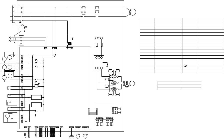
-23-
Controller Box
|
|
L1 |
TB1 |
|
|
|
|
|
L1 |
Red |
|
||
Power source |
L2 |
L2 |
White |
|||
3N~ |
|
|||||
380/400/415V |
|
|
|
|
|
|
50Hz/60Hz |
L3 |
L3 |
Black |
|||
|
|
N |
N |
Blue |
|
|
|
|
|
PE |
|
|
|
|
|
PE |
|
Box body |
||
|
|
|
TB3 |
Box body |
||
|
|
|
|
|
|
|
Inverter |
|
M1 |
|
|
|
|
|
M2 |
|
|
|
||
unit |
|
|
|
|
|
|
|
|
|
S |
|
|
|
|
21 |
|
6 |
|
|
|
SV1 |
|
5 |
|
|
||
S4 |
|
3 |
|
|
||
|
|
|
|
4 |
|
|
|
|
|
|
2 |
CN33 |
|
|
|
|
|
1 |
(6P) |
|
*1 |
|
T1 |
|
3 |
|
|
SV2 |
SV3 |
|
2 |
CN39 |
||
|
1 |
(3P) |
|
|||
|
|
T2 |
|
|
|
|
|
SV |
|
6 |
|
|
|
|
|
5 |
|
|
||
SV4 |
5b |
|
4 |
CN34 |
||
|
|
|
3 |
(6P) |
|
|
|
|
|
|
|
||
|
|
|
|
2 |
|
|
|
|
|
|
1 |
|
|
|
CH2 |
|
1 |
|
|
|
|
|
|
|
|
|
|
|
CH3 |
|
2 |
CN35 |
||
|
|
3 |
(3P) |
|
||
|
|
|
|
|
||
|
|
|
CN38 |
|
|
|
|
63H |
(3P) |
|
|
||
|
|
1 |
|
|
||
|
|
|
|
2 |
|
|
|
|
|
|
3 |
|
|
|
|
|
CN46 |
|
|
|
|
51C |
(3P) 1 |
|
|
||
|
|
|
|
2 |
|
|
|
|
|
|
3 |
|
|
|
CH11 |
|
3 |
|
|
|
|
|
|
|
2 |
CNCH11 |
|
|
|
|
|
1 |
(3P) |
|
A2 |
52 |
|
|
5 |
|
|
A1 |
C1 |
52C1 |
|
4 |
CN52C1 |
|
|
13 |
14 |
|
3 |
(5P) |
|
|
|
|
|
2 |
X07 |
|
|
|
|
|
1 |
|
|
|
|
|
|
|
|
|
|
|
|
|
|
CN12 CN09 |
|
|
|
|
|
|
(2P) |
(2P) |
|
|
|
|
|
1 2 |
1 2 |
|
|
|
|
TH10b |
TH10a |
|
|
51C1 |
|
52C1 |
|
Motor (Compressor) |
2 |
1 |
2 |
1 |
Red |
|
4 |
3 |
4 |
3 |
White |
U |
V MC1 |
|||||
|
|
|
|
Black |
W |
6 |
5 |
6 |
5 |
|
Model 200:24A
Model 250:27A
F3
250VAC 1A F
|
|
|
|
|
|
T01 |
|
|
|
|
|
|
CN20 |
|
|
1 |
2 |
1 |
2 |
3 |
(3P) |
1 |
2 |
CNS1 |
|
|
|
F1 |
|
CNTR |
|
(2P) |
|
|
|
|
(2P) |
||
|
|
|
|
|
250VAC |
|
|
|
|
|
|
|
6.3A F |
|
|
|
|
|
|
|
ZNR01 |
|
|
X01
X02
X03
Control circuit board (CONT board)
X04 |
|
X05 |
|
SSR01 |
|
4 |
3 |
1 |
2 |
SW3-10 are OFF for Model 200. and ON for Model 250.
Detection circuit
Detection circuit
X06 |
|
1 |
CNFC1 2 |
||
|
(6P) |
3 |
|
|
4 |
|
|
5 |
|
|
6 |
CN06 |
CN05 |
CN03 |
CN02 |
CN01 |
CNL |
|
CNLV1 |
CNLV2 |
||
(2P) |
(4P) |
(3P) |
(8P) |
(2P) |
(3P) |
|
(5P) |
(6P) |
||
1 2 |
1 2 3 4 |
1 2 34 |
1 2 3 |
5 6 7 8 |
1 2 |
1 |
2 |
3 |
1 2 3 4 5 |
1 2 3 4 5 6 |
|
Black White Red |
|
|
||
|
3 |
2 |
1 |
LEV1 |
LEV2 |
TH9 TH4 TH3 TH6 TH5 TH8 TH7 |
TH11 |
|
|
|
|
|
63LS |
|
|
||
L3 |
L2 |
L1 |
F2 |
|
F1 |
600VAC |
|
600VAC |
8A F |
|
8A F |
L3 |
L2 |
L1 |
NF |
|
|
|
|
|
||
Noise |
|
|
|
|||||||
|
|
|
|
|
|
|
|
|||
|
|
|
|
|
Filter |
|
|
|
|
|
L3 |
L2 |
L1 |
Box body |
SCRM |
||||||
|
|
|
|
|
|
|
UG1 |
|
|
|
|
White |
|
|
|
|
|
UK2 |
|
|
|
Black |
|
Red |
|
|
|
|
|
K |
G |
|
|
|
|
|
|
|
|
|
L1 |
G |
K |
|
|
|
|
|
|
|
|
|
|
|
|
|
|
|
|
VK1 |
|
|
|
|
|
|
|
|
|
|
VG1 |
|
|
G K |
||
|
|
|
|
|
|
|
|
L2 |
||
|
|
|
|
|
|
|
|
K |
G |
|
|
|
|
|
|
VK2 |
|
|
|||
|
|
|
|
|
|
|
|
|
||
|
|
|
|
|
VG2 |
|
|
G K |
||
|
|
|
|
|
|
|
|
L3 |
||
|
|
|
|
|
|
|
|
K |
G |
|
|
|
|
|
|
|
|
|
|
||
|
|
|
|
|
|
|
WG1 |
|
|
|
|
|
|
|
|
|
|
WK2 |
|
|
|
Fan control board |
|
|
||||||||
(Fancon board) |
|
1 |
|
|
||||||
|
1 |
|
|
|
|
|
|
2 |
|
|
|
2 CNFC2 |
|
CNU 3 |
|
|
|||||
|
43 |
(6P) |
|
|
(5P) 4 |
|
|
|||
|
5 |
|
CNW |
CNV |
|
5 |
|
|
||
|
6 |
|
|
|
|
|
||||
|
|
(5P) |
(5P) |
|
|
|
|
|||
|
|
|
|
|
|
|
||||
5 |
4 |
3 |
2 |
1 |
5 |
4 |
3 |
2 |
1 |
|
|
|
SYMBOL |
NAME |
SYMBOL |
NAME |
|
|
ZNR01 |
VARISTOR |
TH3 |
THERMISTER |
|
|
SSR |
SOLID STATE RELAY |
TH4 |
THERMISTER |
|
|
F1 |
FUSE(6.3A) <CONT BOARD> |
TH5 |
THERMISTER |
|
|
F1,F2 |
FUSE(8A) |
TH6 |
THERMISTER |
|
|
F3 |
FUSE(1A) |
TH7 |
THERMISTER |
|
|
52C1 |
MAGNET CONTACTOR |
TH8 |
THERMISTER |
|
|
51C1 |
OVER CURRENT RELAY |
TH9 |
THERMISTER |
|
|
MC1 |
ELECTRIC MOTOR OF COMPRESSOR |
TH10a |
THERMISTER |
|
|
MF |
FAN MOTOR(HEAT EXCHANGER) |
TH10b |
THERMISTER |
|
|
CH11 |
CRANK CASE HEATER(COMPRESSOR) |
LEV1 |
ELECTRONIC EXPANSION VALVE |
|
|
CH2,CH3 |
CORD HEATER |
LEV2 |
ELECTRONIC EXPANSION VALVE |
|
|
21S4 |
4-WAY VALVE |
X01~X07 |
RELAY |
|
|
SV1,SV4 |
SOLENOID VALVE |
SW2,SW3 |
SWITCH |
|
|
SV5b |
SOLENOID VALVE |
SWU1,2 |
SWITCH |
|
|
SV2,SV3 |
*1 SOLENOID VALVE |
TB1 |
POWER SOURCE TERMINAL BLOCK |
|
|
63H |
HIGH PRESSURE CUT OUT SWITCH |
|
EARTH TERMINAL |
UK1 |
|
63LS |
LOW SIDE PRESSURE SENSOR |
T1,T2 |
TERMINAL |
|
TH11 |
THERMISTER |
|
|
|
UG2 |
|
|
|
||
U |
Red |
|
|
|
|
|
|
|
|
|
|
|
1 |
CNMF |
<Difference of appliance> |
|
|
|
U |
|
|
|
|
V |
2 |
Appliance |
Difference |
|
|
3 |
VWMF |
|
|||
|
|
N |
PUHN-P200·250YMF-C(-BS,-BF) |
ALL exists |
|
|
CN04 |
Fan motor |
|
||
|
|
|
|
||
W |
Black |
(Heat exchanger) |
PUHN- 200·250YMF-C(-BS,-BF) |
"*1" are not existed |
|
|
|
WK1
WG2
UK1
UG1
UK2
UG2
WG2 WK2 |
WG1 WK1 |
VG2 VK2 |
VG1 VK1 |
C-250YMF (P)200,-PUHN

[4] |
Standard Operation Data |
|
|
|
|
|
|
|
|
|
|
|
|
|
|
|
|
||||
1 |
Cooling operation |
|
|
|
|
|
|
|
|
|
|
|
|
|
|
|
|
|
|||
|
|
|
|
|
|
|
|
|
|
|
|
|
|
|
|
|
|
|
|
|
|
|
|
|
|
|
Outdoor unit |
|
PUHY-P400YMF-C |
|
|
|
PUHY-P500YMF-C |
|
|||||||||
Items |
|
|
|
|
|
|
|
|
|
|
|||||||||||
|
|
|
|
|
|
|
|
|
|
|
|
|
|
|
|
|
|
|
|
||
|
|
|
|
|
|
|
|
|
|
|
|
|
|
|
|
|
|
|
|
|
|
|
|
|
Indoor |
|
|
|
|
27.0/19.0 |
|
|
|
|
|
|
27.0/19.0 |
|
|
||||
|
Ambient temp. |
|
|
|
DB/WB |
|
|
|
|
|
|
|
|
|
|
|
|
|
|
|
|
|
Outdoor |
|
|
|
35.0/- |
|
|
|
|
|
|
35.0/- |
|
|
|
||||||
|
|
|
|
|
|
|
|
|
|
|
|
|
|
|
|
||||||
|
|
|
|
|
|
|
|
|
|
|
|
|
|
|
|
|
|
|
|
|
|
|
|
|
Quantity |
|
Set |
|
|
5 |
|
|
|
|
|
|
5 |
|
|
|
|||
|
Indoor unit |
|
|
|
|
|
|
|
|
|
|
|
|
|
|
|
|
|
|
|
|
|
|
Quantity in operation |
|
|
5 |
|
|
|
|
|
|
5 |
|
|
|
||||||
|
|
|
|
|
|
|
|
|
|
|
|
|
|
||||||||
Condition |
|
|
|
|
|
|
|
|
|
|
|
|
|
|
|
|
|
|
|
|
|
|
|
Model |
|
- |
125 |
125 |
|
100 |
|
63 |
32 |
|
125 |
125 |
|
125 |
|
100 |
32 |
||
|
|
|
|
|
|
|
|
|
|||||||||||||
|
|
|
|
|
|
|
|
|
|
|
|
|
|
|
|
|
|
|
|
|
|
|
|
|
Main pipe |
|
|
|
|
5 |
|
|
|
|
|
|
5 |
|
|
|
|||
|
Piping |
|
|
|
|
|
|
|
|
|
|
|
|
|
|
|
|
|
|
|
|
|
|
Branch pipe |
|
m |
10 |
10 |
|
10 |
|
10 |
10 |
|
10 |
10 |
|
10 |
|
10 |
10 |
||
|
|
|
|
|
|
|
|
|
|
|
|
|
|
|
|
|
|
|
|
|
|
|
|
|
Total piping length |
|
|
|
55 |
|
|
|
|
|
|
55 |
|
|
|
||||
|
|
|
|
|
|
|
|
|
|
|
|
|
|
|
|
|
|
|
|
|
|
|
Indoor unit fan notch |
|
- |
Hi |
Hi |
|
Hi |
|
Hi |
Hi |
|
Hi |
Hi |
|
Hi |
|
Hi |
Hi |
|||
|
|
|
|
|
|
|
|
|
|
|
|
|
|
|
|
|
|
|
|
|
|
|
Refrigerant volume |
|
kg |
|
|
22.4 |
|
|
|
|
|
|
27.9 |
|
|
|
|||||
|
|
|
|
|
|
|
|
|
|
|
|
|
|
|
|
|
|
||||
unit |
Total current |
|
A |
|
27.6/26.2/25.2 |
|
|
|
34.6/32.8/31.7 |
|
|||||||||||
Outdoor |
|
|
|
|
|
|
|
|
|
|
|
|
|
|
|
|
|
|
|
|
|
Voltage |
|
|
|
|
V |
|
|
380 ~ 415 |
|
|
|
|
|
380 ~ 415 |
|
|
|||||
|
|
|
|
|
|
|
|
|
|
|
|
|
|
||||||||
|
|
|
|
|
|
|
|
|
|
|
|
|
|
|
|
|
|
|
|
|
|
|
|
|
|
|
|
|
|
|
|
|
|
|
|
|
|
|
|
|
|
|
|
opening |
SC (LEV1) |
|
|
|
|
Pulse |
410 |
410 |
|
164 |
|
360 |
340 |
|
410 |
410 |
|
179 |
|
360 |
280 |
|
Indoor unit |
|
|
|
|
|
|
360 |
|
|
|
410 |
|
||||||||
LEV |
|
|
|
|
|
|
|
|
|
|
|
|
|
|
|
|
|
|
|
|
|
Oil return (SLEV) |
|
|
|
|
200 |
|
|
|
|
|
|
344 |
|
|
|
||||||
|
|
|
|
|
|
|
|
|
|
|
|
|
|
|
|
|
|
|
|
|
|
Pressure |
High pressure/Low pressure |
|
MPa |
|
|
2.11/0.43 |
|
|
|
|
|
2.11/0.42 |
|
|
|
||||||
|
|
|
|
|
|
|
|
|
|
|
|
||||||||||
|
(after O/S) |
|
(before MA) |
|
|
|
|
|
|
|
|
|
|
|
|||||||
|
|
|
|
|
|
|
|
|
|
|
|
|
|
|
|
|
|
|
|||
|
|
|
|
|
|
|
|
|
|
|
|
|
|
|
|
|
|
|
|
|
|
|
|
Discharge (TH11/TH12) |
|
|
|
92/102 |
|
|
|
|
|
|
97/102 |
|
|
|
|||||
|
|
|
|
|
|
|
|
|
|
|
|
|
|
|
|
|
|
|
|
|
|
|
|
Heat exchanger outlet (TH5) |
|
|
|
|
|
|
|
|
42 |
|
|
|
|
|
|
||||
|
|
|
|
|
|
|
|
|
|
|
|
|
|
|
|
|
|
|
|
|
|
|
|
|
|
Inlet |
|
|
|
|
4 |
|
|
|
|
|
|
5 |
|
|
|
||
|
|
Accumulator |
|
|
|
|
|
|
|
|
|
|
|
|
|
|
|
|
|
|
|
|
|
Outlet |
|
|
|
|
6 |
|
|
|
|
|
|
7 |
|
|
|
||||
|
|
|
|
|
|
|
|
|
|
|
|
|
|
|
|
|
|||||
|
|
|
|
|
|
|
|
|
|
|
|
|
|
|
|
|
|
|
|
|
|
|
|
Suction (Comp) (No.1/No.2) |
|
|
|
6/12 |
|
|
|
|
|
|
12/12 |
|
|
|
|||||
|
|
|
|
|
|
|
|
|
|
|
|
|
|
|
|
|
|
|
|
|
|
|
|
Low pressure saturation |
|
|
|
|
|
|
|
|
1 |
|
|
|
|
|
|
||||
|
|
temperature |
(TH2) |
|
|
|
|
|
|
|
|
|
|
|
|
|
|
||||
temperature |
Outdoor |
|
|
|
|
|
|
|
|
|
|
|
|
|
|
|
|
||||
|
|
Lower (TH3) |
|
|
|
|
|
|
|
|
1 |
|
|
|
|
|
|
||||
unit |
|
|
|
|
|
|
|
|
|
|
|
|
|
|
|
|
|||||
|
Liquid level |
Upper (TH4) |
°C |
|
|
|
|
|
|
|
30 |
|
|
|
|
|
|
||||
|
|
|
|
|
|
|
|
|
|
|
|
|
|
|
|||||||
Sectional |
|
|
|
|
|
|
|
|
|
|
|
|
|
|
|
|
|
|
|
||
|
|
|
|
|
|
|
|
|
|
|
|
|
|
|
|
|
|
|
|||
|
|
|
|
|
|
|
|
|
|
|
|
|
|
|
|
|
|
|
|
|
|
|
Shell bottom (Comp No.1/No.2) |
|
|
|
60/51 |
|
|
|
|
|
|
65/50 |
|
|
|
||||||
|
|
|
|
|
|
|
|
|
|
|
|
|
|
||||||||
|
|
|
|
|
|
|
|
|
|
|
|
|
|
|
|
|
|
|
|
|
|
|
|
SCC outlet (TH7) |
|
|
|
|
|
|
|
|
|
27 |
|
|
|
|
|
|
|||
|
|
|
|
|
|
|
|
|
|
|
|
|
|
|
|
|
|
|
|
|
|
|
|
Bypass outlet (TH8) |
|
|
|
|
10 |
|
|
|
|
|
|
11 |
|
|
|
||||
|
|
|
|
|
|
|
|
|
|
|
|
|
|
|
|
|
|
|
|
|
|
|
|
Bypass inlet (TH9a) |
|
|
|
|
2 |
|
|
|
|
|
|
3 |
|
|
|
||||
|
|
|
|
|
|
|
|
|
|
|
|
|
|
|
|
|
|
|
|
||
|
|
CS circuit (TH9b) |
|
|
|
|
|
|
|
|
|
16 |
|
|
|
|
|
|
|||
|
|
|
|
|
|
|
|
|
|
|
|
|
|
|
|
|
|||||
|
|
Circulating configuration (αOC) |
|
|
|
|
|
|
|
0.23 |
|
|
|
|
|
|
|||||
|
|
|
|
|
|
|
|
|
|
|
|
|
|
|
|
|
|
|
|
|
|
|
Indoor |
LEV inlet |
|
|
|
|
|
|
|
|
|
26 |
|
|
|
|
|
|
|||
|
|
|
|
|
|
|
|
|
|
|
|
|
|
|
|
|
|
|
|
|
|
|
unit |
Heat exchanger outlet |
|
|
|
|
|
|
|
|
|
12 |
|
|
|
|
|
|
|||
|
|
|
|
|
|
|
|
|
|
|
|
|
|
|
|
|
|||||
|
|
|
|
|
|
|
|
|
|
|
|
|
|
|
|
|
|
|
|
|
|
-24-
|
Outdoor unit |
- |
PUHY-P600YSMF-C |
PUHY-P700YSMF-C |
|
|
|||
|
|
Variable |
PUHY-P400YMF-C |
PUHY-P500YMF-C |
|
|
capacity unit |
||
|
|
|
|
|
Items |
|
Constant |
PUHN-P200YMF-C |
PUHN-P200YMF-C |
|
capacity unit |
|||
|
|
|
||
Ambient temp. |
Indoor |
DB/WB |
|
27/19.0 |
Outdoor |
|
35/- |
||
|
|
|
|
|
|
Quantity |
|
Set |
|
5 |
|
||||
Condition |
Indoor unit |
|
Quantity in operation |
|
5 |
|
||||||
|
|
|
|
|
||||||||
|
|
|
|
|
|
|
|
|
|
|
|
|
|
|
Model |
|
- |
|
200/200/125/50/25 |
|
250/200/125/100/25 |
|
|||
|
|
|
|
|
|
|
||||||
|
|
|
|
|
|
|
|
|
|
|
|
|
|
|
|
Main pipe |
|
|
|
|
5 |
|
|||
|
Piping |
|
|
|
|
|
m |
|
|
|
|
|
|
|
Branch pipe |
|
|
5 |
|
||||||
|
|
|
|
|
|
|
|
|
|
|
|
|
|
|
|
Total piping length |
|
|
|
30 |
|
||||
|
|
|
|
|
|
|
|
|
|
|
|
|
|
Indoor unit fan notch |
|
- |
|
|
Hi |
||||||
|
|
|
|
|
|
|
|
|
|
|
|
|
|
Refrigerant volume |
|
kg |
28.9 |
|
34.9 |
|
|||||
|
|
|
|
|
|
|
|
|
|
|
|
|
Outdoor unit |
Voltage |
|
|
|
|
|
V |
41.5/39.5/38.0 |
380 ~ 415 |
|
||
|
Current |
|
|
|
|
|
A |
48.3/45.9/44.2 |
|
|||
|
|
|
|
|
|
|
|
|
|
|
|
|
opening |
Indoor unit |
|
|
|
|
|
|
|
360/360/410/360/270 |
|
410/360/410/360/270 |
|
|
|
|
|
|
Pulse |
|
|
|
|
|||
capacity |
Oil return (SLEV) |
|
200 |
|
344 |
|
||||||
|
Variable |
SC (LEV1) |
|
|
|
164 |
|
179 |
|
|||
LEV |
|
|
|
|
|
|
|
|
|
|
|
|
Constant |
SC (LEV1) |
|
|
|
|
116 |
|
|||||
|
capacity |
Liquid pipe (LEV2) |
|
|
|
|
60 |
|
||||
|
|
|
|
|
|
|
||||||
|
|
|
|
|
|
|
|
|
|
|
|
|
Pressure |
High pressure/Low pressure |
|
MPa |
2.11/0.45 |
|
2.11/0.44 |
|
|||||
(after O/S) |
(before Main ACC) |
|
|
|
||||||||
|
|
|
|
|
|
|
||||||
|
|
|
|
|
|
|
|
|
|
|
||
|
|
Discharge (TH11/TH12) |
|
|
92/102 |
|
97/102 |
|
||||
|
|
|
|
|
|
|
|
|
|
|
||
|
|
Heat exchanger outlet (TH5) |
|
|
|
42 |
|
|||||
|
|
|
|
|
|
|
|
|
|
|
|
|
|
|
Accumulator |
Inlet |
|
|
|
6 |
|
5 |
|
||
|
|
|
|
|
|
|
|
|
|
|||
|
|
Outlet |
|
|
|
8 |
|
7 |
|
|||
|
|
|
|
|
|
|
|
|
|
|||
|
|
|
|
|
|
|
|
|
|
|
|
|
|
|
Suction (Comp) |
|
|
|
7/13 |
|
13/13 |
|
|||
|
|
|
|
|
|
|
|
|
|
|
||
|
Variable |
Low pressure saturation |
|
|
2 |
|
1 |
|
||||
|
temperature |
(TH2) |
|
|
|
|
||||||
|
|
|
|
|
|
|
||||||
|
capacity |
|
|
|
|
|
|
|
|
|
|
|
|
|
|
|
Upper (TH4) |
|
|
|
30 |
|
|||
|
unit |
Liquid level |
|
|
|
|
||||||
|
|
|
|
|
|
|
|
|
||||
|
|
|
|
|
Lower (TH3) |
|
|
2 |
|
1 |
|
|
|
|
|
|
|
|
|
|
|
|
|
|
|
temperature |
|
Shell bottom (Comp) |
|
|
|
60/51 |
|
65/50 |
|
|||
|
|
|
|
|
|
|
|
|
|
|
|
|
|
SCC outlet (TH7) |
|
°C |
|
27 |
|
||||||
|
|
|
|
|
||||||||
|
|
|
|
|
|
|
|
|
|
|
||
|
|
Bypass outlet (TH8) |
|
|
|
11 |
|
10 |
|
|||
|
|
|
|
|
|
|
|
|
|
|
||
Sectional |
|
Bypass inlet (TH9a) |
|
|
|
3 |
|
1 |
|
|||
|
|
|
|
|
|
|
|
|
||||
|
Circulating configuration (αOC) |
|
|
|
0.23 |
|
||||||
|
|
CS circuit (TH9b) |
|
|
|
|
16 |
|
||||
|
|
|
|
|
|
|
|
|
|
|
|
|
|
|
Discharge temperature (TH11) |
|
|
|
102 |
|
|||||
|
|
|
|
|
|
|
|
|
|
|
||
|
|
Liquid level |
|
Upper (TH4) |
|
|
|
30 |
|
|||
|
|
|
|
|
|
|
|
|
|
|||
|
Constant |
|
|
|
|
|
4 |
|
||||
|
|
|
|
Lower (TH3) |
|
|
|
|
||||
|
|
|
|
|
|
|
|
|
|
|
|
|
|
|
|
|
|
|
|
|
|
|
|
|
|
|
capacity |
Shell bottom (Comp) |
|
|
|
|
50 |
|
||||
|
unit |
|
|
|
|
|
|
|
|
|
|
|
|
SCC outlet (TH7) |
|
|
|
|
27 |
|
|||||
|
|
|
|
|
|
|
||||||
|
|
|
|
|
|
|
|
|
|
|||
|
|
Bypass outlet (TH8) |
|
|
|
|
13 |
|
||||
|
|
Bypass inlet (TH9) |
|
|
|
|
5 |
|
||||
|
Indoor unit |
LEV inlet |
|
|
|
|
26 |
|
||||
|
Heat exchanger outlet |
|
|
|
|
12 |
|
|||||
|
|
|
|
|
|
|
||||||
|
|
|
|
|
|
|
|
|
|
|
|
|
-25-

|
Outdoor unit |
- |
PUHY-P650YSMF-C |
PUHY-P750YSMF-C |
|
|
|||
|
|
Variable |
PUHY-P400YMF-C |
PUHY-P500YMF-C |
|
|
capacity unit |
||
|
|
|
|
|
Items |
|
Constant |
PUHN-P250YMF-C |
PUHN-P250YMF-C |
|
capacity unit |
|||
|
|
|
||
Ambient temp. |
Indoor |
DB/WB |
|
27/19.0 |
Outdoor |
|
35/- |
||
|
|
|
|
|
|
|
Quantity |
Set |
|
5 |
|
||
Condition |
Indoor unit |
|
Quantity in operation |
|
5 |
|
||||
|
|
|
|
|||||||
|
|
|
|
|
|
|
|
|
|
|
|
|
|
Model |
- |
250/200/125/50/25 |
|
250/250/125/100/25 |
|
||
|
|
|
|
|
|
|||||
|
|
|
|
|
|
|
|
|
|
|
|
|
|
|
Main pipe |
|
|
5 |
|
||
|
|
|
|
|
|
m |
|
|
|
|
|
Piping |
|
Branch pipe |
|
5 |
|
||||
|
|
|
|
|
|
|
|
|
|
|
|
|
|
|
Total piping length |
|
|
30 |
|
||
|
|
|
|
|
|
|
|
|
|
|
|
Indoor unit fan notch |
- |
|
Hi |
||||||
|
|
|
|
|
|
|
|
|
|
|
|
Refrigerant volume |
kg |
31.9 |
|
36.9 |
|
||||
|
|
|
|
|
|
|
|
|
|
|
Outdoor unit |
Voltage |
|
|
|
V |
44.7/42.5/40.9 |
380 ~ 415 |
|
||
|
Current |
|
|
|
A |
51.5/48.9/47.1 |
|
|||
|
|
|
|
|
|
|
|
|
|
|
opening |
Indoor unit |
|
|
|
|
410/360/410/360/270 |
|
410/410/410/360/270 |
|
|
|
|
|
|
Pulse |
|
|
|
|
||
capacity |
Oil return (SLEV) |
200 |
|
344 |
|
|||||
|
Variable |
SC (LEV1) |
|
164 |
|
179 |
|
|||
LEV |
|
|
|
|
|
|
|
|
|
|
Constant |
SC (LEV1) |
|
|
116 |
|
|||||
|
|
|
|
|||||||
|
|
|
|
|
|
|
|
|
||
|
capacity |
Liquid pipe (LEV2) |
|
|
60 |
|
||||
|
|
|
|
|
|
|||||
|
|
|
|
|
|
|
|
|
|
|
Pressure |
High pressure/Low pressure |
MPa |
2.11/0.45 |
|
2.11/0.44 |
|
||||
(after O/S) |
(before Main ACC) |
|
|
|||||||
|
|
|
|
|
|
|
|
|
|
|
|
|
|
Discharge (TH11/TH12) |
|
92/102 |
|
97/102 |
|
||
|
|
|
|
|
|
|
|
|
|
|
|
|
|
Heat exchanger outlet (TH5) |
|
|
42 |
|
|||
|
|
|
|
|
|
|
|
|
|
|
|
|
|
Accumulator |
Inlet |
|
6 |
|
5 |
|
|
|
|
|
|
|
|
|
|
|
||
|
|
|
Outlet |
|
8 |
|
7 |
|
||
|
|
|
|
|
|
|
|
|||
|
|
|
|
|
|
|
|
|
|
|
|
|
|
Suction (Comp) |
|
7/13 |
|
13/13 |
|
||
|
|
|
|
|
|
|
|
|
|
|
|
|
|
Low pressure saturation |
|
2 |
|
1 |
|
||
|
Variable |
temperature (TH2) |
|
|
|
|||||
|
|
|
|
|
|
|||||
|
capacity |
Liquid level |
Upper (TH4) |
|
|
30 |
|
|||
|
unit |
|
|
|
||||||
|
|
|
|
|
|
|
||||
|
|
|
|
|
Lower (TH3) |
|
2 |
|
1 |
|
|
|
|
|
|
|
|
|
|
|
|
temperature |
|
|
Shell bottom (Comp) |
|
60/51 |
|
65/50 |
|
||
|
|
|
|
|
|
|
|
|
|
|
|
|
SCC outlet (TH7) |
°C |
|
27 |
|
||||
|
|
|
|
|
||||||
|
|
|
|
|
|
|
|
|
|
|
|
|
|
Bypass outlet (TH8) |
|
11 |
|
10 |
|
||
|
|
|
|
|
|
|
|
|
|
|
Sectional |
|
|
Bypass inlet (TH9a) |
|
3 |
|
2 |
|
||
|
|
|
|
|
|
|
|
|||
|
|
Circulating configuration (αOC) |
|
|
0.23 |
|
||||
|
|
|
CS circuit (TH9b) |
|
|
16 |
|
|||
|
|
|
|
|
|
|
|
|
|
|
|
|
|
Discharge temperature (TH11) |
|
|
102 |
|
|||
|
|
|
|
|
|
|
|
|
|
|
|
|
|
Liquid level |
Upper (TH4) |
|
|
30 |
|
||
|
|
|
|
|
|
|
|
|
||
|
Constant |
Lower (TH3) |
|
|
3 |
|
||||
|
|
|
|
|
|
|||||
|
|
|
|
|
|
|
|
|
||
|
Shell bottom (Comp) |
|
|
50 |
|
|||||
|
capacity |
|
|
|
||||||
|
unit |
|
|
|
|
|
|
|
|
|
|
SCC outlet (TH7) |
|
|
27 |
|
|||||
|
|
|
|
|
|
|||||
|
|
|
|
|
|
|
|
|||
|
|
|
Bypass outlet (TH8) |
|
|
12 |
|
|||
|
|
|
Bypass inlet (TH9) |
|
|
4 |
|
|||
|
|
|
|
|
|
|
|
|||
|
Indoor unit |
|
LEV inlet |
|
|
26 |
|
|||
|
|
Heat exchanger outlet |
|
|
12 |
|
||||
|
|
|
|
|
|
|||||
-26-

Outdoor unit
Items |
|
|
|
|
|
|
PUHY-400YMF-C |
|
|
|
|
PUHY-500YMF-C |
|
|||||||||
|
|
|
|
|
|
|
|
|
|
|
|
|
|
|
|
|
|
|
|
|
||
|
|
|
|
|
|
|
|
|
|
|
|
|
|
|
|
|
|
|
|
|
|
|
|
|
|
Indoor |
|
|
|
|
27.0/19.0 |
|
|
|
|
|
|
|
27.0/19.0 |
|
|
||||
|
Ambient temp. |
|
|
|
DB/WB |
|
|
|
|
|
|
|
|
|
|
|
|
|
|
|
|
|
|
Outdoor |
|
|
|
35.0/- |
|
|
|
|
|
|
|
35.0/- |
|
|
|
||||||
|
|
|
|
|
|
|
|
|
|
|
|
|
|
|
|
|
||||||
|
|
|
|
|
|
|
|
|
|
|
|
|
|
|
|
|
|
|
|
|
|
|
|
|
|
Quantity |
|
Set |
|
|
5 |
|
|
|
|
|
|
|
5 |
|
|
|
|||
|
Indoor unit |
|
|
|
|
|
|
|
|
|
|
|
|
|
|
|
|
|
|
|
|
|
|
|
Quantity in operation |
|
|
5 |
|
|
|
|
|
|
|
5 |
|
|
|
||||||
|
|
|
|
|
|
|
|
|
|
|
|
|
|
|
||||||||
Condition |
|
|
|
|
|
|
|
|
|
|
|
|
|
|
|
|
|
|
|
|
|
|
|
|
Model |
|
- |
125 |
125 |
|
100 |
|
63 |
32 |
|
|
125 |
125 |
|
125 |
|
100 |
32 |
||
|
|
|
|
|
|
|
|
|
|
|
|
|
|
|
|
|
|
|
|
|
|
|
|
|
Main pipe |
|
|
|
|
5 |
|
|
|
|
|
|
|
5 |
|
|
|
||||
|
|
|
|
|
|
|
|
|
|
|
|
|
|
|
|
|
|
|
|
|
|
|
|
Piping |
|
|
|
|
|
|
|
|
|
|
|
|
|
|
|
|
|
|
|
|
|
|
|
Branch pipe |
|
m |
10 |
10 |
|
10 |
|
10 |
10 |
|
|
10 |
10 |
|
10 |
|
10 |
10 |
||
|
|
|
|
|
|
|
|
|
|
|
|
|
|
|
|
|
|
|
|
|
|
|
|
|
|
Total piping length |
|
|
|
55 |
|
|
|
|
|
|
|
55 |
|
|
|
||||
|
|
|
|
|
|
|
|
|
|
|
|
|
|
|
|
|
|
|
|
|
|
|
|
Indoor unit fan notch |
|
- |
Hi |
Hi |
|
Hi |
|
Hi |
Hi |
Hi |
Hi |
|
Hi |
|
Hi |
Hi |
|||||
|
|
|
|
|
|
|
|
|
|
|
|
|
|
|
|
|
|
|
|
|
|
|
|
Refrigerant volume |
|
kg |
|
|
22.4 |
|
|
|
|
|
|
|
27.9 |
|
|
|
|||||
|
|
|
|
|
|
|
|
|
|
|
|
|
|
|
|
|
|
|
||||
unit |
Total current |
|
A |
|
27.6/26.2/25.2 |
|
|
|
|
33.7/32.0/30.8 |
|
|||||||||||
Outdoor |
|
|
|
|
|
|
|
|
|
|
|
|
|
|
|
|
|
|
|
|
|
|
Voltage |
|
|
|
|
V |
|
|
380 ~ 415 |
|
|
|
|
|
|
380 ~ 415 |
|
|
|||||
|
|
|
|
|
|
|
|
|
|
|
|
|
|
|
|
|
|
|
|
|
|
|
|
|
|
|
|
|
|
|
|
|
|
|
|
|
|
|
|
|
|
|
|
|
|
opening |
Indoor unit |
|
|
|
|
|
430 |
430 |
|
380 |
|
380 |
350 |
|
|
430 |
430 |
|
430 |
|
380 |
290 |
|
|
|
|
|
Pulse |
|
|
|
|
|
|
|
|
|
|
|
|
|
|
|
|
|
SC (LEV1) |
|
|
|
|
|
|
164 |
|
|
|
|
|
|
|
179 |
|
|
|
||||
LEV |
|
|
|
|
|
|
|
|
|
|
|
|
|
|
|
|
|
|
|
|
|
|
Oil return (SLEV) |
|
|
|
|
|
|
|
|
344 |
|
|
|
|
|
|
|
||||||
|
|
|
|
|
|
|
|
|
|
|
|
|
|
|
|
|
|
|
|
|
|
|
Pressure |
High pressure/Low pressure |
|
MPa |
|
|
1.96/0.43 |
|
|
|
|
|
|
|
1.96/0.42 |
|
|
||||||
(after O/S) |
|
(before MA) |
|
|
|
|
|
|
|
|
|
|
|
|
||||||||
|
|
|
|
|
|
|
|
|
|
|
|
|
|
|
|
|
|
|
||||
|
|
|
|
|
|
|
|
|
|
|
|
|
|
|
|
|
|
|
|
|
|
|
|
|
|
|
|
|
|
|
|
|
|
|
|
|
|
|
|
|
|
|
|
|
|
|
|
Discharge (TH11/TH12) |
|
|
|
90/95 |
|
|
|
|
|
|
|
95/100 |
|
|
|
|||||
|
|
|
|
|
|
|
|
|
|
|
|
|
|
|
|
|
|
|
|
|
|
|
|
|
Heat exchanger outlet (TH5) |
|
|
|
|
|
|
|
42 |
|
|
|
|
|
|
|
|||||
|
|
|
|
|
|
|
|
|
|
|
|
|
|
|
|
|
|
|
|
|
|
|
|
|
|
|
Inlet |
|
|
|
|
2 |
|
|
|
|
|
|
|
5 |
|
|
|
||
|
|
Accumulator |
|
|
|
|
|
|
|
|
|
|
|
|
|
|
|
|
|
|
|
|
|
|
Outlet |
|
|
|
|
4 |
|
|
|
|
|
|
|
5 |
|
|
|
||||
|
|
|
|
|
|
|
|
|
|
|
|
|
|
|
|
|
|
|||||
|
|
|
|
|
|
|
|
|
|
|
|
|
|
|
|
|
|
|
|
|
|
|
temperature |
|
Suction (Comp) (No.1/No.2) |
|
|
|
4/10 |
|
|
|
|
|
|
|
10/10 |
|
|
|
|||||
|
|
|
|
|
|
|
|
|
|
|
|
|
|
|
|
|
|
|
|
|
||
Outdoor |
Low pressure saturation |
|
|
|
|
|
|
|
3 |
|
|
|
|
|
|
|
|
|||||
temperature |
(TH2) |
|
|
|
|
|
|
|
|
|
|
|
|
|
|
|
||||||
unit |
|
|
|
|
|
|
|
|
|
|
|
|
|
|
|
|
|
|||||
|
|
|
|
|
|
|
|
|
|
|
|
|
|
|
|
|
|
|
|
|
||
|
|
|
|
|
°C |
|
|
|
|
|
|
|
|
|
|
|
|
|
|
|
|
|
|
|
|
Upper (TH4) |
|
|
|
|
|
|
30 |
|
|
|
|
|
|
|
|||||
Sectional |
|
Liquid level |
|
|
|
|
|
|
|
|
|
|
|
|
|
|||||||
|
|
|
|
|
|
|
|
|
|
|
|
|
|
|
|
|
|
|
|
|||
|
Lower (TH3) |
|
|
|
|
|
|
|
3 |
|
|
|
|
|
|
|
|
|||||
|
|
|
|
|
|
|
|
|
|
|
|
|
|
|
|
|
|
|||||
|
|
|
|
|
|
|
|
|
|
|
|
|
|
|
|
|
|
|
|
|
|
|
|
|
Shell bottom (Comp No.1/No.2) |
|
|
|
60/51 |
|
|
|
|
|
|
|
65/50 |
|
|
|
|||||
|
|
|
|
|
|
|
|
|
|
|
|
|
|
|
|
|
|
|
|
|
|
|
|
|
SCC outlet (TH7) |
|
|
|
|
|
|
|
|
27 |
|
|
|
|
|
|
|
||||
|
|
|
|
|
|
|
|
|
|
|
|
|
|
|
|
|
|
|
|
|
|
|
|
|
Bypass outlet (TH8) |
|
|
|
|
8 |
|
|
|
|
|
|
|
9 |
|
|
|
||||
|
|
|
|
|
|
|
|
|
|
|
|
|
|
|
|
|
|
|
|
|
|
|
|
|
|
|
|
|
|
|
|
|
|
|
|
|
|
|
|
|
|
|
|
|
|
|
|
Bypass inlet (TH9) |
|
|
|
|
4 |
|
|
|
|
|
|
|
5 |
|
|
|
||||
|
|
|
|
|
|
|
|
|
|
|
|
|
|
|
|
|
|
|
|
|
|
|
|
Indoor |
LEV inlet |
|
|
|
|
|
|
|
|
26 |
|
|
|
|
|
|
|
||||
|
|
|
|
|
|
|
|
|
|
|
|
|
|
|
|
|
|
|
|
|
|
|
|
unit |
Heat exchanger outlet |
|
|
|
|
|
|
|
|
10 |
|
|
|
|
|
|
|
||||
|
|
|
|
|
|
|
|
|
|
|
|
|
|
|
|
|
||||||
|
|
|
|
|
|
|
|
|
|
|
|
|
|
|
|
|
|
|
|
|
|
|
-27-
 Loading...