


 Loading...
Mitsubishi Electronics QS90SR2SP-CC, QS90SR2SN-EX, QS90SR2SN-CC, QS90SR2SP-EX, QS90SR2SN-Q User Manual
Safety Relay Module
User's Manual
-QS90SR2SP-Q -QS90SR2SN-Q -QS90SR2SP-CC -QS90SR2SN-CC -QS90SR2SP-EX -QS90SR2SN-EX
 SAFETY PRECAUTIONS
(Always read these instructions before using this equipment.)
Before using the product, please read this manual, the relevant manuals introduced in this manual, standard programmable controller manuals, and the safety standards carefully and pay full attention to safety to handle the product correctly.
In this manual, the safety instructions are ranked as " WARNING" and "
 CAUTION".
 WARNING
 CAUTION
Indicates that incorrect handling may cause hazardous conditions, resulting in death or severe injury.
Indicates that incorrect handling may cause hazardous conditions, resulting in minor or moderate injury or property damage.
Note that the  CAUTION level may lead to a serious consequence according to the circumstances. Always follow the instructions of both levels because they are important to personal safety.
Please save this manual to make it accessible when required and always forward it to the end user.
[Design Precautions]
 WARNING
●A safety relay module turns OFF all outputs by safety input or a failure of external power supply. Create an external circuit to securely stop the power of hazard by turning OFF the outputs. Incorrect configuration may result in an accident.
●When overcurrent due to such as load short-circuit or load current exceeding the rating flows for a long time, it may cause smoke or fire. To prevent this, create external safety circuit such as a fuse.
●Create short-circuit current protection for a safety relay and a protection circuit such as a fuse and breaker, outside a safety relay module.
●To inhibit a restart without manual operation after safety function of the safety relay module was performed and outputs were turned OFF, create reset start-up circuit using such as a reset switch outside the safety relay module.
●The safety relay module may consume excessive current due to a failure. If this occurs, the DC power supply connected to the safety power supply part (+24V (SAFETY) and 24G (SAFETY) terminals) of the module detects an overcurrent and may shut off the output. To the DC power supply connected to the safety relay module, connect only the equipment and the devices that will not affect the system even if they are simultaneously stopped due to power-off.
●Use an extension module whose input type is the same as that of the main module. The modules of different input types (input P and N types) cannot be connected.
A - 1
[Design Precautions]
 CAUTION
●The safety category is evaluated by the whole equipment. Make sure that the whole equipment meets the requirements before use.
●Use the programmable controller in an environment that meets the general specifications contained in this manual.
Using this programmable controller in an environment outside the range of the general specifications could result in electric shock, fire, erroneous operation, and damage to or deterioration of the product.
●The life of safety relay used for the safety relay module depends on the open-close condition and load. Be sure to operate the equipment by use conditions to make sure that the number of allowable times that the relay opens/closes.
●Do not install the wiring of external devices or communication cables together with the main circuit or power lines, or bring them close to each other. Keep a distance of 100mm (3.94 inch) or more between them.
Not doing so could result in noise that would cause erroneous operation.
[Installation Precautions]
 WARNING
●Do not use the product in flammable gas atmosphere or explosive gas atmosphere.
Doing so may result in fire or explosion due to such as an arc caused by opening/closing the relays.
 CAUTION
●For Q series safety relay module, while pressing the module mounting lever located at the bottom of a module, fully insert the module fixing projection into the fixing hole on the base unit. Then, mount the module with the fixing hole as a supporting point.
Incorrect loading of the module can cause a malfunction, failure or drop.
When using the programmable controller in the environment of much vibration, tighten the module with a screw.
Tighten the screw in the specified torque range. Undertightening can cause a drop, short circuit or malfunction.
Overtightening can cause a drop, short circuit or malfunction due to damage to the screw or module.
●Make sure to fix CC-Link safety relay module and extension safety relay module with a DIN rail fixing bracket.
A - 2
[Installation Precautions]
 CAUTION
●Be sure to shut off all phases of the external supply power used by the system before mounting/ removing a module.
Not doing so may result in damage to the product.
●When mounting a module, make room for 5cm (1.97 inch) or more at above and below of the module for ventilation.
When powering ON a contact at 3A or more consecutively, make room for 5mm (0.20 inch) or more at the sides of the contact for ventilation.
●Do not directly touch the module's conductive parts or electronic components. Doing so may cause malfunctions or a failure.
●Securely connect connectors for each cable to the applied parts. Not doing so may cause a malfunction due to poor connection.
[Wiring Precautions]
 WARNING
●Be sure to shut off all phases of the external supply power used by the system before wiring. Not completely turning off all power could result in electric shock or damage to the product.
●When energizing or operating the module after installation or wiring, be sure to close the attached terminal cover.
Not doing so may result in electric shock.
A - 3
 CAUTION
●Ground the FG and LG terminals correctly.
Not doing so could result in electric shock or malfunctions.
●Wire the module correctly after confirming the rated voltage and terminal layout.
Connecting a power supply of a different rated voltage or incorrect wiring may cause a fire or failure.
●Be sure there are no foreign substances such as sawdust or wiring debris inside the module. Such debris could cause a fire, failure, or malfunctions.
●Tighten a terminal block mounting screw, terminal screw, and module mounting screw within the specified torque range.
If the terminal block mounting screw or terminal screw is too loose, it may cause a short circuit, fire, or malfunctions. If too tight, it may damage the screw and/or the module, resulting in a drop of the screw or module, a short circuit or malfunctions.
If the module mounting screw is too loose, it may cause a drop of the screw or module. Over tightening the screw may cause a drop due to the damage of the screw or module.
●Be sure to fix the communication cables or power cables by ducts or clamps when connecting them to the module.
Failure to do so may cause damage of the module or cables due to a wobble, unintentional shifting, or accidental pull of the cables, or malfunctions due to poor contact of the cable.
A - 4
[Wiring Precautions]
 CAUTION
●When removing the connected communication cables or power cables, do not pull the cable with grasping the cable part.
Remove the cable connected to the terminal block after loosening the terminal block screws. Pulling the cable connected to a module may result in malfunctions or damage of the module or cable.
●Use applicable solderless terminals and crimp them with a tool specified by maker. Imperfect connections could result in short circuit, fires, or erroneous operation.
●A protective film is attached to the top of the Q series safety relay module to prevent foreign matter such as wire chips from entering the module during wiring.
Do not peel this label during wiring.
Before starting system operation, be sure to peel this label because of heat dissipation.
●Install our programmable controller in a control panel complying with the IP standard of 54 or more. Wire the main power supply to the power supply module installed in a control panel through a distribution terminal block.
Furthermore, the wiring and replacement of a power supply module have to be performed by a maintenance worker who acquainted with shock protection.
For wiring method, refer to the QCPU User's Manual (Hardware Design, Maintenance and Inspection).
●Do not install the control lines together with the communication cables or bring them close to each other.
Doing so may cause a malfunction due to noise.
●Pay attention when using a flathead screwdriver to push the open/close button of the spring clamp terminal block. Failure to do so can result in an injury.
[Startup and Maintenance Precautions]
 WARNING
●Do not touch the terminals while power is on. Doing so could result in electric shock.
●Turn off all phases of the external supply power used in the system when cleaning the module or retightening the terminal block mounting screws, terminal screws, or module mounting screws. Not doing so could result in electric shock.
Tighten a terminal block mounting screw and module mounting screw within the specified torque range.
If the terminal block mounting screw is too loose, it may cause a short-circuit, fire or malfunctions. If too tight, it may damage the screw and/or the module, resulting in a drop of the screw or module, a short circuit or malfunctions.
If the module mounting screw is too loose, it may cause a drop of the screw or module. Over tightening the screw may cause a drop due to the damage of the screw or module.
A - 5
[Startup and Maintenance Precautions]
 CAUTION
●Do not disassemble or remodel the module. Doing so could cause a failure, malfunctions, injury, or fire.
If the product is repaired or remodeled by other than the specified FA centers or us, the warranty is not covered.
●A electric fuse for overcurrent prevention is incorporated in the control circuit part of the safety relay module.
If the electric fuse operates, power OFF the module once, and power it ON again after resolving the failure.
●Restrict the mounting/removal of a module, base unit, and terminal block up to 50 times (IEC61131- 2-compliant), after the first use of the product.
Failure to do so may cause the module to malfunction due to poor contact of connector.
●Since the module case is made of resin, do not drop or apply any strong impact to the module. Doing so may damage the module.
●Completely turn off the externally supplied power used in the system before mounting or removing the module to/from the panel.
Not doing so may result in a failure or malfunctions of the module.
●Use any radio communication device such as a cellular phone or a PHS phone more than 25cm (9.85 inch) away in all directions of the programmable controller.
Not doing so can cause a malfunction.
●Before touching the module, always touch grounded metal, etc. to discharge static electricity from human body, etc.
Not doing so can cause the module to fail or malfunction.
[Disposal Precautions]
 CAUTION
● When disposing of this product, treat it as industrial waste.
A - 6
 CONDITIONS OF USE FOR THE PRODUCT
(1)Although MELCO has obtained the certification for Product's compliance to the international safety standard ISO13849-1 from TUV Rheinland, this fact does not guarantee that Product will be free from any malfunction or failure. The user of this Product shall comply with any and all applicable safety standard, regulation or law and take appropriate safety measures for the system in which the Product is installed or used and shall take the second or third safety measures other than the Product. MELCO is not liable for damages that could have been prevented by compliance with any applicable safety standard, regulation or law.
(2)MELCO prohibits the use of Products with or in any application involving, and MELCO shall not be liable for a default, a liability for defect warranty, a quality assurance, negligence or other tort and a product liability in these applications.
(a)power plants,
(b)trains, railway systems, airplanes, airline operations, other transportation systems,
(c)hospitals, medical care, dialysis and life support facilities or equipment,
(d)amusement equipments,
(e)incineration and fuel devices,
(f)handling of nuclear or hazardous materials or chemicals,
(g)mining and drilling,
(h)and other applications where the level of risk to human life, health or property are elevated.
A - 7

REVISIONS
|
|
|
|
* The manual number is given on the bottom left of the back cover. |
|
|
|
|
|
|
|
Print date |
*Manual number |
|
|
|
Revision |
Apr., 2008 |
SH(NA)-080746ENG-A |
|
First edition |
||
|
|
|
|
|
|
|
|
|
Partial corrections |
||
Jun., 2008 |
SH(NA)-080746ENG-B |
|
COMPLIANCE WITH THE EMC AND LOW VOLTAGE DIRECTIVES, |
||
|
|
|
Section 5.1.1, 5.1.4, 5.2.1, 5.3.1, 6.1.2, 6.2.2, 6.3.2 |
||
|
|
|
|
|
|
|
|
|
|
|
|
Nov., 2008 |
SH(NA)-080746ENG-C |
|
Partial corrections |
||
|
Section 3.1, 3.2.2, 3.4.1, 5.4.1, 5.4.7 |
||||
|
|
|
|||
|
|
|
|
|
|
|
|
|
|
|
|
Jan., 2010 |
SH(NA)-080746ENG-D |
|
Partial corrections |
||
|
Section 2.2, 3.1, 3.2.1, 3.2.2, 3.3.1, 3.3.2, 3.4.1, 3.4.2, 5.4.1, 5.4.7 |
||||
|
|
|
|||
|
|
|
|
|
|
|
|
|
|
|
|
|
|
|
Addition |
||
|
|
|
CONDITIONS OF USE FOR THE PRODUCT, Section 1.1, 2.3, 2.4 |
||
|
|
|
|
|
|
|
|
|
Partial corrections |
||
Apr., 2015 |
SH(NA)-080746ENG-E |
|
SAFETY PRECAUTIONS, ABOUT MANUALS, COMPLIANCE WITH THE EMC, |
||
|
|
|
LOW VOLTAGE, AND MACHINERY DIRECTIVES, Section 1.3, 1.4, 2.2, 2.4, |
||
|
|
|
3.1, 3.2.1, 3.3.1, 3.3.2, 3.4.2, 3.5, 3.6, Chapter 4, Section 4.3, 4.5, 5.1.1, 5.1.2, |
||
|
|
5.1.3, 5.1.4, 5.2.1, 5.2.3, 5.2.4, 5.3.1, 5.3.2, 5.3.3, 5.4.1, 5.4.2, 5.4.3, 5.4.6, 5.4.7, |
|||
|
|
|
6.1.1, 6.1.2, 6.2.1, 6.2.2, 6.3.1, 6.3.2, APPENDIX 1.1 |
||
|
|
|
|
|
|
|
|
|
|
|
|
Japanese Manual Version SH-080745-F This manual confers no industrial property rights or any rights of any other kind, nor does it confer any licenses.
Mitsubishi Electric Corporation cannot be held responsible for any problems involving industrial property rights which may occur as a result of using the contents noted in this manual.
 2008 MITSUBISHI ELECTRIC CORPORATION
A - 8
INTRODUCTION
Thank you for choosing the Mitsubishi safety relay module.
Before using this product, please read this manual carefully to develop full familiarity with the functions and performance of the safety relay module to ensure correct use.
This product can be used for configuring safety functions of typical industrial machinery.
CONTENTS |
|
SAFETY PRECAUTIONS ................................................................................................................................. |
A - 1 |
CONDITIONS OF USE FOR THE PRODUCT.................................................................................................. |
A - 7 |
REVISIONS....................................................................................................................................................... |
A - 8 |
INTRODUCTION............................................................................................................................................... |
A - 9 |
CONTENTS ...................................................................................................................................................... |
A - 9 |
ABOUT MANUALS ......................................................................................................................................... |
A - 12 |
COMPLIANCE WITH THE EMC, LOW VOLTAGE, AND MACHINERY DIRECTIVES .................................. |
A - 13 |
GENERIC TERMS AND ABBREVIATIONS.................................................................................................... |
A - 14 |
PACKING LIST ............................................................................................................................................... |
A - 14 |
CHAPTER 1 OVERVIEW |
1 - 1 to 1 - 5 |
|
||
|
1.1 |
Product List...................................................................................................................................... |
1 - 1 |
|
|
1.2 |
About Safety Relay Module ............................................................................................................. |
1 - 2 |
|
|
1.3 |
Features........................................................................................................................................... |
1 - 3 |
|
|
1.4 |
Checking the Safety Relay Module Model....................................................................................... |
1 - 5 |
|
CHAPTER 2 SYSTEM CONFIGURATION |
2 - 1 to 2 - 4 |
|
||
|
2.1 |
System Configuration ...................................................................................................................... |
2 - 1 |
|
|
2.2 |
Applicable Systems ......................................................................................................................... |
2 - 2 |
|
|
2.3 |
Module Replacement....................................................................................................................... |
2 - 4 |
|
|
2.4 |
Precautions for Use ......................................................................................................................... |
2 - 4 |
|
CHAPTER 3 SPECIFICATIONS |
3 - 1 to 3 - 15 |
|
||
|
3.1 |
General Specifications..................................................................................................................... |
3 - 1 |
|
3.2 |
Q Series Safety Relay Module Specifications ................................................................................. |
3 - 2 |
|
|
|
3.2.1 QS90SR2SP-Q Q series safety relay module .......................................................................... |
3 - 2 |
|
|
|
3.2.2 QS90SR2SN-Q Q series safety relay module.......................................................................... |
3 - 4 |
||
3.3 |
CC-Link Safety Relay Module Specifications .................................................................................. |
3 - 6 |
|
|
|
3.3.1 QS90SR2SP-CC CC-Link safety relay module ........................................................................ |
3 - 6 |
|
|
|
3.3.2 QS90SR2SN-CC CC-Link safety relay module........................................................................ |
3 - 8 |
|
|
3.4 |
Extension Safety Relay Module Specifications.............................................................................. |
3 - 10 |
|
|
|
3.4.1 QS90SR2SP-EX extension safety relay module .................................................................... |
3 - 10 |
||
|
3.4.2 QS90SR2SN-EX extension safety relay module.................................................................... |
3 - 12 |
|
|
|
3.5 |
I/O Signals ..................................................................................................................................... |
3 - 14 |
|
A - 9

3.6 Cable Specifications ...................................................................................................................... |
3 - 15 |
CHAPTER 4 FUNCTIONS |
4 - 1 to 4 - 5 |
|
||
|
4.1 |
Dual Input Function.......................................................................................................................... |
4 - 1 |
|
|
4.2 |
Start-up/off Check Function ............................................................................................................. |
4 - 2 |
|
|
4.3 |
Start-up Method Selection Function ................................................................................................ |
4 - 3 |
|
|
4.4 |
Safety Output Function .................................................................................................................... |
4 - 3 |
|
|
4.5 |
Monitor Function .............................................................................................................................. |
4 - 4 |
|
|
4.6 |
Partial Shutdown Function with Extension Module.......................................................................... |
4 - 5 |
|
CHAPTER 5 SETTINGS AND PROCEDURES BEFORE OPERATION |
5 - 1 to 5 - 35 |
|
||
|
5.1 Q Series Safety Relay Module......................................................................................................... |
5 - 1 |
|
|
5.1.1 |
Start-up procedures .................................................................................................................. |
5 - 1 |
||
5.1.2 |
Handling precautions................................................................................................................ |
5 - 3 |
|
|
|
5.1.3 Part names and settings........................................................................................................... |
5 - 4 |
||
5.1.4 |
Mounting/removal ..................................................................................................................... |
5 - 6 |
||
|
5.2 CC-Link Safety Relay Module.......................................................................................................... |
5 - 9 |
|
|
5.2.1 |
Start-up procedures .................................................................................................................. |
5 - 9 |
||
5.2.2 |
Handling precautions.............................................................................................................. |
5 - 11 |
|
|
|
5.2.3 Part names and settings......................................................................................................... |
5 - 12 |
|
|
5.2.4 |
Station number setting............................................................................................................ |
5 - 14 |
|
|
5.2.5 |
Module installation direction ................................................................................................... |
5 - 14 |
|
|
|
5.3 Extension Safety Relay Module..................................................................................................... |
5 - 15 |
|
|
5.3.1 |
Start-up procedures ................................................................................................................ |
5 - 15 |
|
|
5.3.2 |
Handling precautions.............................................................................................................. |
5 - 17 |
|
|
|
5.3.3 Part names and settings......................................................................................................... |
5 - 18 |
|
|
5.3.4 |
Module installation direction ................................................................................................... |
5 - 20 |
|
|
|
5.4 Wiring............................................................................................................................................. |
5 - 21 |
|
|
|
5.4.1 Precautions for safety devices and wiring .............................................................................. |
5 - 21 |
|
|
|
5.4.2 Spring clamp terminal block.................................................................................................... |
5 - 30 |
|
|
|
5.4.3 Attaching/removing a terminal block....................................................................................... |
5 - 33 |
|
|
|
5.4.4 Precautions for handling CC-Link dedicated cable................................................................. |
5 - 33 |
||
|
5.4.5 Connecting with CC-Link dedicated cables ............................................................................ |
5 - 34 |
|
|
|
5.4.6 Precautions for wiring power supply ....................................................................................... |
5 - 34 |
|
|
5.4.7 |
Connecting extension modules............................................................................................... |
5 - 35 |
|
|
CHAPTER 6 TROUBLESHOOTING |
6 - 1 to 6 - 7 |
|
||
6.1 |
Q Series Safety Relay Module......................................................................................................... |
6 - 2 |
|
|
|
6.1.1 Error check method with LED ................................................................................................... |
6 - 2 |
|
|
|
6.1.2 Error check method with monitor signal.................................................................................... |
6 - 3 |
|
|
6.2 |
CC-Link Safety Relay Module.......................................................................................................... |
6 - 4 |
|
|
|
6.2.1 Error check method with LED ................................................................................................... |
6 - 4 |
|
|
|
6.2.2 Error check method with monitor signal.................................................................................... |
6 - 5 |
|
|
6.3 |
Extension Safety Relay Module....................................................................................................... |
6 - 6 |
|
|
|
6.3.1 Error check method with LED ................................................................................................... |
6 - 6 |
|
|
A - 10

6.3.2 Error check method with monitor signal ................................................................................... |
6 - 7 |
APPENDIX |
|
App - 1 to App - 4 |
|
|
|
Appendix 1 External Dimensions......................................................................................................... |
App - 1 |
||
|
Appendix 1.1 |
Q series safety relay module.................................................................................... |
App - 1 |
|
|
Appendix 1.2 |
CC-Link safety relay module .................................................................................... |
App - 2 |
|
|
Appendix 1.3 |
Extension safety relay module ................................................................................. |
App - 3 |
|
A - 11

ABOUT MANUALS
The manuals related to this product are shown below.
Refer to the following table when ordering required manuals.
Related manuals
|
Manual name |
Manual number |
|
(model code) |
|
|
|
|
|
QCPU User's Manual (Hardware Design, Maintenance and Inspection) |
SH(NA)-080483ENG |
|
This manual explains the specifications of the CPU module, power supply module, base unit, |
|
|
extension cable, and memory card. |
(13JR73) |
|
(Sold separately.) |
|
|
|
|
|
CC-Link System Master/Local Module Type AJ61BT11/A1SJ61BT11 User's Manual |
IB(NA)-66721 |
|
This manual explains the system configuration, performance specifications, functions, handling, |
|
|
wiring, and troubleshooting of the AJ61BT11 and A1SJ61BT11. |
(13J872) |
|
(Sold separately.) |
|
|
|
|
|
CC-Link System Master/Local Module Type AJ61QBT11/A1SJ61QBT11 User's Manual |
IB(NA)-66722 |
|
This manual explains the system configuration, performance specifications, functions, handling, |
|
|
wiring, and troubleshooting of the AJ61QBT11 and A1SJ61QBT11. |
(13J873) |
|
(Sold separately.) |
|
|
|
|
|
MELSEC-Q CC-Link System Master/Local Module User's Manual |
SH(NA)-080394E |
|
This manual explains the system configuration, performance specifications, functions, handling, |
|
|
wiring, and troubleshooting of the QJ61BT11N. |
(13JR64) |
|
(Sold separately.) |
|
|
|
|
|
Type Q80BD-J61BT11N/Q81BD-J61BT11 CC-Link System Master/Local Interface Board |
|
|
User's Manual (For SW1DNC-CCBD2-B) |
SH-080527ENG |
|
This manual explains the system configuration, performance specifications, functions, handling, |
|
|
(13JR77) |
|
|
wiring, and troubleshooting of the Q80BD-J61BT11N and Q81BD-J61BT11. |
|
|
|
|
|
(Sold separately.) |
|
|
|
|
A - 12
COMPLIANCE WITH THE EMC, LOW VOLTAGE, AND MACHINERY DIRECTIVES
(1)Method of ensuring compliance
To ensure that Mitsubishi programmable controllers maintain EMC, Low Voltage, and Machinery Directives when incorporated into other machinery or equipment, certain measures may be necessary. Please refer to one of the following manuals.
•User's manual for the CPU module used
•Safety Guidelines
(This manual is included with the base unit.)
The CE mark on the side of the programmable controller indicates compliance with EMC, Low Voltage, and Machinery Directives.
(a)Sales representative in EU member states
The sales representative in EU member states is: Company: Mitsubishi Electric Europe BV
Address: Gothaer Strasse 8,40880 Ratingen, Germany
(2)Additional measures
This product complies with the EMC, Low Voltage, and Machinery Directives. Before using this product, please read this manual, the relevant manuals, the manuals for standard programmable controllers, and the safety standards carefully and pay full attention to safety to handle the product correctly.
The descriptions are based on the requirements of the Directives and the harmonized standards. However, they do not guarantee that the entire machinery constructed according to the descriptions complies with the EMC, Low Voltage, and Machinery Directives.
The manufacture of the machinery must determine the testing method for compliance and declare conformity to the EMC, Low Voltage, and Machinery Directives.
A - 13

GENERIC TERMS AND ABBREVIATIONS
Unless otherwise specified, this manual uses the following generic terms and abbreviations to explain the safety relay module.
Generic term/abbreviation |
Description |
|
Q series safety relay module |
Generic term for QS90SR2SP-Q and QS90SR2SN-Q |
|
CC-Link safety relay module |
Generic term for QS90SR2SP-CC and QS90SR2SN-CC |
|
Extension safety relay module |
Generic term for QS90SR2SP-EX and QS90SR2SN-EX |
|
Safety relay module |
Generic term for Q series safety relay module, CC-Link safety relay module, and |
|
extension safety relay module |
||
|
||
Main module |
Generic term for Q series safety relay module and CC-Link safety relay module |
|
Extension module |
Abbreviation for extension safety relay module |
PACKING LIST |
|
The following tables show the packing list of each product. |
|
(1) Safety relay module |
|
|
|
Product |
Quantity |
Safety relay module |
1 |
|
|
Hardware manual |
1 |
(2) Safety circuit part extension cable
Product |
Quantity |
QS90CBL-SE01 |
1 |
|
|
QS90CBL-SE15 |
1 |
A - 14

1 OVERVIEW
1
CHAPTER 1 OVERVIEW
This manual explains specifications, handling, and wiring methods of the safety relay module.
1.1Product List
|
Table 1.1 Product list |
|
|
|
|
Product name |
Model name |
Description |
|
QS90SR2SP-Q |
A safety relay module mounted on a MELSEC-Q series base unit |
|
Input P type (Dual input with positive commons) |
|
|
|
|
Q series safety relay module |
|
|
|
A safety relay module mounted on a MELSEC-Q series base unit |
|
|
QS90SR2SN-Q |
Input N type (Dual input with positive common and negative |
|
|
common) |
|
QS90SR2SP-CC |
A safety relay module connected to the CC-Link network |
|
Input P type (Dual input with positive commons) |
|
|
|
|
CC-Link safety relay module |
|
|
|
A safety relay module connected to the CC-Link network |
|
|
QS90SR2SN-CC |
Input N type (Dual input with positive common and negative |
|
|
common) |
|
QS90SR2SP-EX |
An extension safety relay module |
|
Input P type (Dual input with positive commons) |
|
|
|
|
Extension safety relay module |
|
|
|
An extension safety relay module |
|
|
QS90SR2SN-EX |
Input N type (Dual input with positive common and negative |
|
|
common) |
|
|
OVERVIEW |
|
|
|
|
|
2 |
|
||
|
SYSTEM |
CONFIGURATION |
|
|
|
|
|
|
3 |
|
|
|
|
SPECIFICATIONS |
|
|
|
|
|
|
4 |
|
|
|
|
FUNCTIONS |
|
|
|
|
|
|
5 |
|
|
|
SETTINGS AND PROCEDURES BEFORE |
OPERATION |
|
|
|
|
|
|
6 |
|
|
|
|
TROUBLESHOOTING |
|
APPENDIX
|
|
|
|
|
|
|
|
|
|
1.1 Product List |
1 - 1 |
|
|
|
1 OVERVIEW
1.2About Safety Relay Module
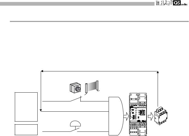
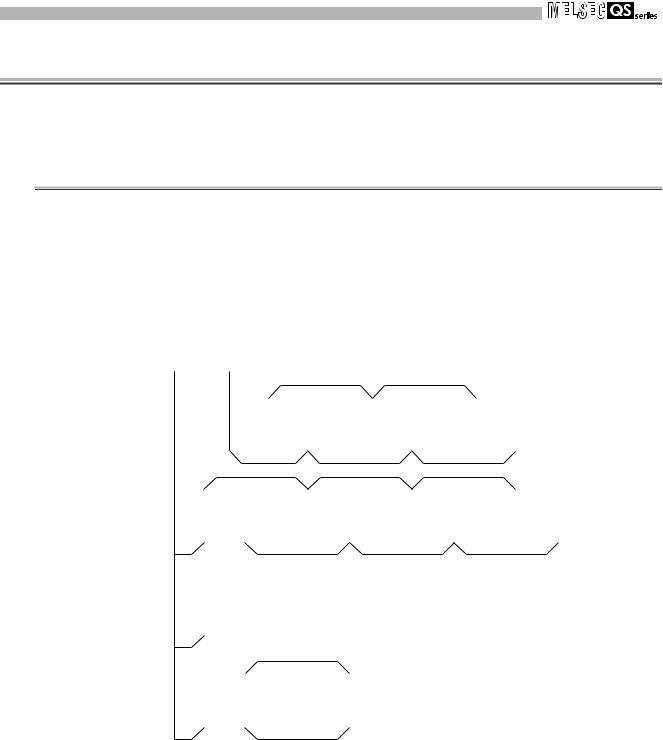
The safety relay module achieves basic safety functions for emergency stop only by wiring, without programming.
It is safety check type module whose output does not turn ON until all conditions of the safety input (normally closed contact), off check input (normally closed contact), and startup switch (normally open contact) are met.
Using the module helps to reduce the man-hour taken for configuring a safety check system.
Safety input
(Emergency stop switch, light curtain, etc.)
Safety input |
Off check input |
|
|
||
|
Start-up switch |
|
Start-up input |
Such as |
|
electromagnetic |
||
|
||
|
switch |
|
|
Safety relay module |
|
|
Figure 1.1 Safety relay module |
1 - 2 |
1.2 About Safety Relay Module |

1 OVERVIEW
1
1.3Features
This section explains features of the safety relay module.
(1)Obtaining the highest level of safety approval
The safety relay module obtained the highest safety approval (Category 4 of EN ISO13849-1/performance level E) that the programmable controller can be gained (In some conditions, Category 3/performance level D can be gained).
A system ensuring higher safety can be configured.
(2)Category 3 and Category 4 compliant
A system complying with Category 3 or Category 4 of EN ISO13849-1 can be configured depending on the safety input device to be connected and rated current.
Table 1.2 Conditions for complying with each category |
|
||||
|
|
|
|
|
|
|
Safety input device to be |
Rated current |
|||
|
connected |
||||
Condition |
|
|
|||
Contact-type |
Type 4 light |
|
|
||
|
5.0A max. |
3.6A max. |
|||
|
input device |
curtain |
|||
|
|
|
|||
Dual input with positive |
|
|
|
Category 3 or |
|
commons |
Category 3 |
Category 4 |
Category 3 |
||
Category 4 |
|||||
(Input P type) |
|
|
|
||
|
|
|
|
||
Dual input with positive |
|
Not |
|
|
|
common and negative common |
Category 4 |
Category 3 |
Category 4 |
||
connectable |
|||||
(Input N type) |
|
|
|
||
|
|
|
|
||
(3)Safety standards
Use this product according to the following safety standards.
|
Table 1.3 Safety standards |
|
|
|
|
Region |
Standard |
|
Global |
ISO13849-1: 2006, IEC60204-1/A1: 2008, IEC61496-1: 2012 |
|
Europe |
EN ISO13849-1: 2008, EN60204-1/A1: 2009, EN61496-1: 2013, |
|
EN50178: 1997, EN55011/A1: 2010, EN61000-6-2: 2005 |
||
|
||
North America |
UL508 |
(4)Monitoring safety control with the MELSEC-Q series is possible.
Mounting/connecting the safety relay module on/to existing MELSEC-Q series programmable controller allows monitoring operating status of the whole safety relay module and error status of the module.
|
|
OVERVIEW |
|
|
|
|
|
2 |
|
||
|
SYSTEM |
CONFIGURATION |
|
|
|
|
|
|
3 |
|
|
|
|
SPECIFICATIONS |
|
|
|
|
|
|
4 |
|
|
|
|
FUNCTIONS |
|
|
|
|
|
|
5 |
|
|
|
SETTINGS AND PROCEDURES BEFORE |
OPERATION |
|
|
|
|
|
|
6 |
|
|
|
|
TROUBLESHOOTING |
|
APPENDIX
|
|
|
|
|
|
|
|
|
|
1.3 Features |
1 - 3 |
|
|
|
1 OVERVIEW
(5)Small-scale safety control
The safety relay module is suited for small-scale safety control whose number of I/O points is around 10.
(a)Programming is unnecessary.
Safety circuits can be easily created only by wiring, without programming and settings.
Since an inspection on programming by safety certification organization is unnecessary, the man-hour taken for obtaining the safety approval can be omitted.
(b)Extension of safety circuit with extension module
By connecting extension safety relay modules, maximum 4 points of safety input and maximum 4 points of safety output can be controlled.
(c)Safety control can be performed by itself.
Since a communication circuit for Q series programmable controller and CC-Link is separated from a circuit for achieving the safety function, the safety relay module can perform safety control by itself, independent of a failure of the Q series programmable controller or CC-Link communication status.
(6)Fail safe
Fail safe can be achieved by inhibiting the safety relay module from starting when an error occurs in safety input, start-up input, and/or internal circuit of the safety relay module.
(7)Improvement of efficiency in wiring work
Using spring clamp terminal block allows to skip screw tightening work and to reduce wiring work significantly.
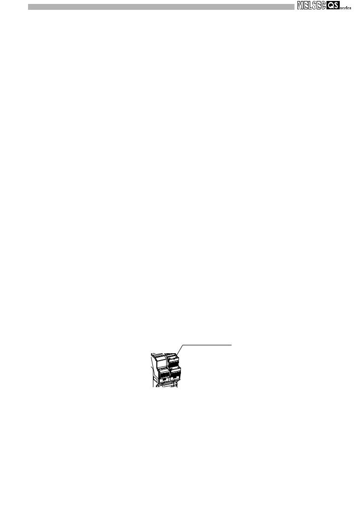
(8)Connector insertion check
Using terminal block cover for connector insertion check prevents poor connection. If the terminal block is not inserted securely, the terminal block cover does not close.
Terminal block cover
Figure 1.2 Terminal block cover
1 - 4 |
1.3 Features |
1 OVERVIEW
1.4Checking the Safety Relay Module Model
This section explains how to check the safety relay module model.
QS90SR2S P - Q
Q: For Q series
CC: For CC-Link
EX: For extension
P: Input P type (dual input with positive commons)
N: Input N type (dual input with positive common and negative common)
Figure 1.3 Checking the safety relay module model
1
|
|
OVERVIEW |
|
|
|
|
|
2 |
|
||
|
SYSTEM |
CONFIGURATION |
|
|
|
|
|
|
3 |
|
|
|
|
SPECIFICATIONS |
|
|
|
|
|
|
4 |
|
|
|
|
FUNCTIONS |
|
|
|
|
|
|
5 |
|
|
|
SETTINGS AND PROCEDURES BEFORE |
OPERATION |
|
|
|
|
|
|
6 |
|
|
|
|
TROUBLESHOOTING |
|
|
|
|
|
|
|
|
|
|
|
APPENDIX |
|
|
|
|
|
|
|
|
|
|
|
1.4 Checking the Safety Relay Module Model |
1 - 5 |
|
|
|
2 SYSTEM CONFIGURATION
CHAPTER 2 SYSTEM CONFIGURATION
This chapter explains the system configuration, precautions for use, and system equipment of the safety relay module.
2.1System Configuration
Figure 2.1 shows system configuration using the safety relay module.
module supply Power |
module CPU |
station Master |
|
relay safety series Q module |
|
|
|
|
|
|
|
|
|
|
|
|
|
|
|
|
|
|
|
|
|
|
|
|
|
|
|
|
|
|
|
|
|
|
|
Safety part |
|||
|
|
|
|
|
|
|
|
|
|
|
|
|
|
|
|
|
|
||||
|
|
|
|
|
|
|
|
|
|
|
|
|
|
|
|
|
|
|
|
|
|
|
|
|
|
|
|
Extension |
|
|
Extension |
|
|
Extension |
|
|
|||||||
|
|
|
|
|
|
|
safety |
|
|
|
safety |
|
|
|
safety |
|
|
||||
|
|
|
|
|
relay module |
|
|
relay module |
|
relay module |
|
|
|||||||||
|
|
|
|
|
|
|
|
|
|
|
|
|
|
|
|
|
|
|
|
|
|
|
|
|
|
|
|
|
|
|
|
|
|
|
|
|
|
|
|
|
Communication part |
||
|
|
|
|
|
|
|
|
|
|
|
|
|
|
|
|
|
|
|
Safety part |
||
|
|
|
|
|
|
|
|
|
|
|
|
|
|
|
|
|
|
||||
|
|
|
CC-Link safety |
|
|
|
Extension |
|
|
Extension |
|
|
|
Extension |
|
||||||
|
|
|
|
|
|
safety |
|
|
safety |
|
|
|
safety |
|
|||||||
|
|
|
relay module |
|
|
|
|
|
|
|
|
|
|||||||||
|
|
|
|
|
|
relay module |
|
|
relay module |
|
|
relay module |
|
||||||||
|
|
|
|
|
|
|
|
|
|
|
|
|
|
||||||||
|
|
|
|
|
|
|
|
|
|
|
|
|
|
|
|
|
|
|
|
|
|
|
|
|
|
|
|
|
|
|
|
|
|
|
|
|
|
|
|
|
|
Communication part |
|
|
|
|
|
|
|
|
|
|
|
|
|
|
|
|
|
|
|
|
|
|
|
|
|
|
|
Remote I/O |
|
|
|
|
|
|
|
|
|
|
|
|
|
|
|
|
|
|
|
|
|
station |
|
|
|
|
|
|
|
|
|
|
|
|
|
|
|
|
|
|
|
|
|
|
|
|
|
|
|
|
|
|
|
|
|
|
|
|
|
|
|
CC-Link safety |
|
Extension |
|
safety |
|
relay module |
|
|
|
relay module |
|
|
|
|
|
|
|
Figure 2.1 System configuration
2 - 1 |
2.1 System Configuration |
2 SYSTEM CONFIGURATION
2.2Applicable Systems
(1)Mountable modules, the number of mountable modules, and mountable base units
(a)Q series safety relay module
1)When mounting to CPU module
The following table shows the mountable CPU modules, the number of mountable modules, and mountable base units of the Q series safety relay module.
Shortage of power capacity may occur depending on the combination with other mounted modules or the number of mounted modules.
When mounting modules, pay attention to the power capacity.
When shortage of power capacity occurs, review the combination of modules
to be mounted.
Table 2.1 Applicable modules and the number of mountable modules
|
Mountable CPU module |
Number of |
Mountable base unit*2 |
|||
|
|
|
mountable |
|
|
|
CPU type |
CPU model |
Main base unit |
Extension base |
|||
modules*1 |
unit |
|||||
|
|
|
|
|||
|
|
Q00JCPU |
Up to 8 |
|
|
|
|
Basic model QCPU |
Q00CPU |
Up to 12 |
|
|
|
|
|
Q01CPU |
|
|
||
|
|
|
|
|
||
|
|
Q02(H)CPU |
|
|
|
|
|
High Performance |
Q06HCPU |
Up to 32 |
|
|
|
|
model QCPU |
Q12HCPU |
|
|
||
|
|
|
|
|||
|
|
Q25HCPU |
|
|
|
|
|
|
Q02PHCPU |
|
|
|
|
|
Process CPU |
Q06PHCPU |
Up to 32 |
|
|
|
|
Q12PHCPU |
|
|
|||
|
|
|
|
|
||
|
|
Q25PHCPU |
|
|
|
|
|
|
Q00UJCPU |
Up to 8 |
|
|
|
Programmable |
|
Q00UCPU |
Up to 12 |
|
|
|
controller CPU |
|
Q01UCPU |
|
|
||
|
|
|
|
|||
|
|
Q02UCPU |
Up to 18 |
|
|
|
|
|
Q03UD(E)CPU |
|
|
|
|
|
Universal model |
Q04UD(E)HCPU |
|
|
|
|
|
Q06UD(E)HCPU |
|
|
|
||
|
QCPU |
|
|
|
||
|
Q10UD(E)HCPU |
|
|
|
||
|
|
|
|
|
||
|
|
Q13UD(E)HCPU |
Up to 32 |
|
|
|
|
|
Q20UD(E)HCPU |
|
|
|
|
|
|
Q26UD(E)HCPU |
|
|
|
|
|
|
Q50UDEHCPU |
|
|
|
|
|
|
Q100UDEHCPU |
|
|
|
|
|
Redundant CPU |
Q12PRHCPU |
Up to 31 |
|
|
|
|
Q25PRHCPU |
|
|
|||
|
|
|
|
|
||
|
|
Q06CCPU-V |
|
|
|
|
C Controller module |
Q06CCPU-V-B |
Up to 32 |
|
|
||
|
|
Q12DCCPU-V |
|
|
|
|
 : Mountable,
  : Not mountable
*1: Limited within the range of the number of I/O points for the CPU module.
*2: Mountable on any I/O slots of the mountable base unit.
2.2 Applicable Systems |
2 - 2 |
1
|
|
OVERVIEW |
|
|
|
|
|
2 |
|
||
|
SYSTEM |
CONFIGURATION |
|
|
|
|
|
|
3 |
|
|
|
|
SPECIFICATIONS |
|
|
|
|
|
|
4 |
|
|
|
|
FUNCTIONS |
|
|
|
|
|
|
5 |
|
|
|
SETTINGS AND PROCEDURES BEFORE |
OPERATION |
|
|
|
|
|
|
6 |
|
|
|
|
TROUBLESHOOTING |
|
|
|
|
|
|
|
|
|
|
|
APPENDIX |
|
|
|
|
|
|
|
|
|
|
|
|
|
2 SYSTEM CONFIGURATION
2)When mounting to remote I/O station in MELSECNET/H connection
The following table shows the mountable network modules, the number of mountable modules, and mountable base units of the Q series safety relay module.
Shortage of power capacity may occur depending on the combination with other mounted modules or the number of mounted modules.
When mounting modules, pay attention to the power capacity.
When shortage of power capacity occurs, review the combination of modules to be mounted.
Table 2.2 Network modules and the number of mountable modules
|
Number of |
Mountable base unit*2 |
||
Mountable network |
mountable |
Main base unit on |
Extension base unit |
|
module |
on remote I/O |
|||
modules*1 |
remote I/O station |
|||
|
station |
|||
|
|
|
||
QJ72LP25-25 |
|
|
|
|
QJ72LP25G |
Up to 32 |
|
|
|
QJ72BR15 |
|
|
|
|
|
|
: Mountable, : Not mountable |
||
*1: Limited within the range of the number of I/O points for the network module.
*2: Mountable on any I/O slots of the mountable base unit.
(b)CC-Link safety relay module
The CC-Link safety relay module is used as remote I/O station.
For system configuration of the CC-Link system, refer to the Control & Communication Link System Master/Local Module User's Manual.
(c)Extension safety relay module
Up to three extension safety relay modules can be added to a Q series safety relay module or CC-Link safety relay module.
For extension method, refer to Section 5.3.
2 - 3 |
2.2 Applicable Systems |
2 SYSTEM CONFIGURATION
1
2.3Module Replacement
Replace the product according to the replacement cycle shown in the table below.
Table 2.3 Module replacement cycle
Module |
Module replacement cycle |
Q series/CC-Link/Extension safety relay module |
10 years |
2.4Precautions for Use
Users must prove that their entire safety system complies with the safety standards and the Machinery Directive. The third-party certification organization will validate the safety of product for the entire safety system, including a safety relay module and safety components.
To establish a safety system, calculate the target performance level (PL) for each safety application (safety function) based on the MTTFd and DCavg values of the safety relay module and connected safety components. The calculation equation is shown in ISO13849-1:2006.
MTTFd and DCavg of the safety relay module are shown in following.
|
Table 2.4 MTTFd and DCavg of the safety relay module |
|
||
|
|
|
|
|
Module |
|
MTTFd |
DCavg |
|
Safety relay module |
|
>100 years |
|
99% |
|
|
OVERVIEW |
|
|
|
|
|
2 |
|
||
|
SYSTEM |
CONFIGURATION |
|
|
|
|
|
|
3 |
|
|
|
|
SPECIFICATIONS |
|
|
|
|
|
|
4 |
|
|
|
|
FUNCTIONS |
|
|
|
|
|
|
5 |
|
|
|
SETTINGS AND PROCEDURES BEFORE |
OPERATION |
|
|
|
|
|
|
6 |
|
|
|
|
TROUBLESHOOTING |
|
APPENDIX
|
|
|
|
|
|
|
|
|
|
2.3 Module Replacement |
2 - 4 |
|
|
|
3 SPECIFICATIONS
CHAPTER 3 SPECIFICATIONS
3.1General Specifications
Table 3.1 shows the general specifications of the safety relay module.
|
|
Table 3.1 General specifications |
|
|
|
|
|
||
|
|
|
|
|
|
|
|
|
|
Item |
|
|
|
Specifications |
|
|
|||
Operating ambient |
|
|
|
0 to 55 |
|
|
|
|
|
temperature |
|
|
|
|
|
|
|
||
|
|
|
|
|
|
|
|
|
|
Storage ambient |
|
|
|
-25 to 75 |
*3 |
|
|
|
|
temperature |
|
|
|
|
|
|
|||
|
|
|
|
|
|
|
|
|
|
Operating ambient humidity |
|
|
|
30 to 85%RH, non-condensing |
|
|
|||
Storage ambient humidity |
|
|
|
|
|
||||
|
|
|
|
|
|
|
|
|
|
|
|
|
|
Frequency |
|
Constant |
|
Half |
Sweep count |
|
|
|
|
acceleration |
|
amplitude |
|||
|
|
|
|
|
|
|
|||
|
JIS B 3502, |
Under |
|
5 to 8.4Hz |
|
- |
|
3.5mm |
10 times each |
|
intermittent |
|
|
|
(0.14inch) |
in X, Y, Z |
|||
Vibration resistance |
IEC 61131-2 |
|
|
|
|
|
|||
vibration |
|
8.4 to 150Hz |
|
9.8m/s2 |
|
- |
directions |
||
|
compliant |
|
|
|
|||||
|
Under |
|
5 to 8.4Hz |
|
- |
|
1.75mm |
|
|
|
|
|
|
|
|
||||
|
|
continuous |
|
|
|
(0.069inch) |
- |
||
|
|
|
|
|
|
|
|||
|
|
vibration |
|
8.4 to 150Hz |
|
4.9m/s2 |
|
- |
|
|
|
|
JIS B 3502, IEC 61131-2 compliant |
|
|
||||
Shock resistance |
(147m/s2, duration of action 11ms, 3 times each in 3 directions X, Y, Z by sine half-wave |
||||||||
|
|
|
|
pulse) |
|
|
|
|
|
Operating ambience |
|
|
|
No corrosive gases |
|
|
|||
Operating altitude*4 |
|
|
|
0 to 2000m |
|
|
|||
Installation location |
|
Inside of control panel of IP standard 54 or more |
|
||||||
Overvoltage category*1 |
|
|
|
III or less |
|
|
|||
Pollution degree*2 |
|
|
|
2 or less |
|
|
|||
Equipment class |
|
|
|
Class I |
|
|
|||
*1: This indicates the section of the power supply to which the equipment is assumed to be connected between the public electrical power distribution network and the machinery within the premises.
Category III applies to devices in fixed equipment such as a switching device and industrial machine.
The surge voltage withstand level of equipment for up to the rated voltage of 300V is 4000V.
*2: This index indicates the degree to which a conductive material is generated in the environment where the equipment is used.
Pollution degree 2 is when only non-conductive pollution occurs. However, temporary conductivity may be produced due to incidental condensation.
*3: The storage ambient temperature is -20 to 75 if the system includes any CC-Link safety relay modules or extension safety relay modules.
*4: Do not use or store the programmable controller under pressure higher than the atmospheric pressure of altitude 0m.
Doing so may cause a malfunction.
When using the programmable controller under pressure, please contact your local Mitsubishi office.
3 - 1 |
3.1 General Specifications |
3 SPECIFICATIONS
1
3.2Q Series Safety Relay Module Specifications
This section explains the specifications of the Q series safety relay module.
3.2.1QS90SR2SP-Q Q series safety relay module
Table 3.2 Performance specifications of QS90SR2SP-Q (1/2)
|
Item |
|
|
|
Q series safety relay module |
|
|
|
|
|
|
QS90SR2SP-Q |
|
||
|
|
|
|
|
|
||
|
|
Input specifications |
|
Output specifications |
|||
|
|
|
|
|
|
|
|
Number of safety input points |
1 safety input point (2 inputs) |
|
Number of safety output points |
1 safety output point (3 outputs) |
|||
Number of other input points |
1 start-up input point |
|
Insulation method |
Relay insulation |
|||
Insulation method |
|
Relay insulation |
|
Rated load current |
Category 3: 5.0A/point or less |
||
Safety input rated input voltage |
24VDC (ripple ratio: within 5%) |
|
Category 4: 3.6A/point or less*1 |
||||
|
|
||||||
Safety input rated input current |
4.6mA (300mA at relay start-up) |
|
Minimum switching load |
5VDC/5mA |
|||
Operating voltage range |
|
20.4 to 26.4VDC |
|
Maximum allowable voltage of |
250VAC, 30VDC |
||
|
|
contact |
|||||
|
|
|
|
|
|
||
|
|
Type |
P type |
|
|
|
|
Input format |
|
X0 |
Positive common |
|
Resistance load |
250VAC/5A, 30VDC/5A |
|
|
|
X1 |
Positive common |
|
|
|
|
Relay life |
|
Mechanical |
Five million times or more |
|
|
|
|
|
Electrical |
Hundred thousand times or more |
|
|
|
||
|
|
|
|
|
|||
Maximum switching frequency |
1,200 times/hour based on the rated control capacity |
|
|||||
Response |
Time until output ON |
50ms or less (safety input ON |
safety output ON)*2 |
|
|||
time |
Time until output OFF |
20ms or less (safety input OFF |
safety output OFF) |
|
|||
Common wiring method |
|
All safety inputs and safety outputs are independent. |
|
||||
Number of extension modules |
Up to three extension safety relay modules can be connected. |
|
|||||
Number of occupied I/O points |
32 points, 2 slots (I/O assignment: Input) |
|
|||||
Internal current consumption (5VDC) |
0.09A |
|
|
|
|||
Module power supply |
Voltage |
24VDC (ripple ratio: within 5%) (allowable voltage range: 20.4 to 26.4VDC) |
|
||||
Current |
35mA (when not using extension module), 110mA (when using three extension modules) |
||||||
|
|
||||||
Safety power supply |
Voltage |
24VDC (ripple ratio: within 5%) (allowable voltage range: 20.4 to 26.4VDC) |
|
||||
Current |
85mA (when not using extension module), 325mA (when using three extension modules) |
||||||
|
|
||||||
Noise durability |
|
DC type noise voltage: 500Vp-p, noise width: 1 s, |
|
||||
|
noise frequency: 25 to 60Hz (noise simulator condition) |
|
|||||
|
|
|
|
||||
|
|
|
2,500VAC/1mA or less for 1 minute between safety outputs |
|
|||
Dielectric withstand voltage |
2,500VAC/1mA or less for 1 minute between safety input and safety output |
|
|||||
|
|
|
2,500VAC/1mA or less for 1 minute between power supply and safety output |
|
|||
|
|
|
100M or more, measured with a 500VDC insulation resistance tester between safety outputs |
||||
Insulation resistance |
|
100M or more, measured with a 500VDC insulation resistance tester between safety input and safety output |
|||||
|
|
|
100M or more, measured with a 500VDC insulation resistance tester between power supply and safety output |
||||
Level of protection |
|
IP1X |
|
|
|
||
Weight |
|
|
0.37kg |
|
|
|
|
External connection method |
Two-piece spring clamp terminal block |
|
|||||
|
Safety input part |
|
|
|
|
||
|
Start-up input part |
|
|
|
|
||
|
Safety power supply part |
|
|
|
|
||
|
Module power supply |
AWG: 24 to 18, 0.2 to 0.75mm2 |
|
|
|
||
Applicable |
part |
|
|
|
|
||
|
|
|
|
|
|||
wire size |
Extension |
|
|
|
|
|
|
|
communication part |
|
|
|
|
||
|
terminal block |
|
|
|
|
||
|
Safety output part |
AWG: 24 to 14, 0.2 to 2.5mm2 |
|
|
|
||
|
terminal block |
|
|
|
|||
|
|
|
|
|
|||
Applicable |
solderless terminal (bar |
Refer to Section 5.4. |
|
|
|
||
terminal) |
|
|
|
|
|
||
|
|
|
|
|
|
||
|
|
|
|
|
|
|
|
*1: Category 4 is complied only when connecting a light curtain of Type 4.
*2: Manual operation such as start-up switch operation is excluded.
|
|
OVERVIEW |
|
|
|
|
|
2 |
|
||
|
SYSTEM |
CONFIGURATION |
|
|
|
|
|
|
3 |
|
|
|
|
SPECIFICATIONS |
|
|
|
|
|
|
4 |
|
|
|
|
FUNCTIONS |
|
|
|
|
|
|
5 |
|
|
|
SETTINGS AND PROCEDURES BEFORE |
OPERATION |
|
|
|
|
|
|
6 |
|
|
|
|
TROUBLESHOOTING |
|
APPENDIX
3.2 Q Series Safety Relay Module Specifications |
3 - 2 |
3.2.1 QS90SR2SP-Q Q series safety relay module

3 SPECIFICATIONS |
|
|
|
|
|
|
||
|
Table 3.2 Performance specifications of QS90SR2SP-Q (2/2) |
|
|
|||||
External connection diagram |
|
|
Connector |
Pin |
Signal name |
|||
|
|
number |
||||||
|
|
|
|
|
|
|
|
|
|
|
|
|
|
|
|
1 |
+24V |
|
|
|
|
|
|
|
2 |
|
|
|
|
|
|
|
Module power |
|
|
|
|
|
|
TH |
|
3 |
|
|
|
|
|
Fuse |
|
supply part |
24G |
||
|
|
|
|
4 |
||||
|
|
+24V |
5A |
0.9A |
|
|
|
|
24VDC (Module |
|
|
|
|
5 |
FG |
||
|
|
|
DC/DC |
|
||||
power supply) |
|
|
|
|
1 |
EA |
||
24G |
|
|
|
|
||||
|
|
|
|
|
Extension |
2 |
EB |
|
|
|
|
|
|
|
|||
|
|
FG |
|
|
|
communication |
3 |
EG |
|
|
|
|
|
|
part |
4 |
SLD |
|
|
EA |
|
|
|
|
5 |
EP |
|
|
Monitor |
Q bus |
|
1 |
+24V (SAFETY) |
||
|
|
EB |
|
|||||
|
|
circuit |
I/F |
|
2 |
24G (SAFETY) |
||
Connected to an |
|
EG |
circuit |
|
||||
|
|
|
|
|||||
extension module |
|
SLD |
|
|
|
|
3 |
XS0*3*4 |
|
|
|
|
|
|
|||
|
|
EP |
|
|
|
Safety input |
4 |
XS1*3*4 |
|
|
|
|
|
|
|||
Safety circuit part |
|
|
|
|
part |
5 |
COM0*5 |
|
extension cable |
OUT |
|
|
|
|
6 |
X0*4 |
|
or |
|
|
|
|
|
|||
safety part terminating |
|
|
|
|
|
7 |
COM1*6 |
|
connector |
|
Fuse |
TH |
|
|
|||
|
|
|
|
|
8 |
X1*4 |
||
|
|
|
0.9A |
24VDC |
|
|||
|
|
+24V |
5A |
|
||||
|
|
|
|
|
|
1 |
Z00 |
|
24VDC (Safety |
(SAFETY) |
|
|
|
|
|||
power supply) |
24G |
|
|
|
|
2 |
Z01 |
|
|
|
|
|
|
|
|||
Start-up |
|
(SAFETY) |
|
|
GND |
Safety output |
3 |
Z10 |
|
|
|
|
|||||
switch |
|
XS0 |
|
|
|
part |
4 |
Z11 |
|
|
|
|
|
||||
MC0 |
MC1 |
XS1 |
|
|
|
|
5 |
Z20 |
COM0 |
|
Internal |
|
|
||||
|
Control |
|
|
|
6 |
Z21 |
||
24V IN |
X0 |
|
safety circuit |
|
||||
|
output 1 |
COM1 |
|
|
|
|
|
|
|
Control |
|
|
|
|
|
|
|
0V IN |
X1 |
|
|
|
|
|
|
|
|
output 2 |
|
|
|
|
|
|
|
Safety light curtain |
|
|
K0 |
K1 |
|
|
|
|
MC0 |
|
Z00 |
|
|
|
|
|
|
|
Z01 |
|
|
|
|
|
|
|
|
|
|
|
|
|
|
|
|
MC1 |
|
Z10 |
|
|
|
|
|
|
|
Z11 |
|
|
|
|
|
|
|
|
|
|
|
|
|
|
|
|
Safety relay |
|
Z20 |
|
|
|
|
|
|
Motor M |
|
Z21 |
|
|
|
|
|
|
|
|
|
|
|
|
|
|
|
*3: When connecting an electromagnetic switch and such for output, connect its normally closed contacts in series between XS0 and XS1.
*4: Do not connect equipment other than a switch or sensor to each terminal of X0, X1, XS0, and XS1.
*5: Common terminals for X0 and X1 differ. Connect X0 to COM0.
*6: Common terminals for X0 and X1 differ. Connect X1 to COM1.
3 - 3 |
3.2 Q Series Safety Relay Module Specifications |
|
3.2.1 QS90SR2SP-Q Q series safety relay module |
3 SPECIFICATIONS
1
3.2.2QS90SR2SN-Q Q series safety relay module
Table 3.3 Performance specifications of QS90SR2SN-Q (1/2)
|
Item |
|
|
|
Q series safety relay module |
|
|
|
|
|
|
QS90SR2SN-Q |
|
||
|
|
|
|
|
|
||
|
|
Input specifications |
|
Output specifications |
|||
Number of safety input points |
1 safety input point (2 inputs) |
|
Number of safety output points |
1 safety output point (3 outputs) |
|||
Number of other input points |
1 start-up input point |
|
Insulation method |
Relay insulation |
|||
Insulation method |
|
Relay insulation |
|
Rated load current |
Category 4: 3.6A/point or less |
||
Safety input rated input voltage |
24VDC (ripple ratio: within 5%) |
|
(Category 3: 5.0A/point or less) |
||||
|
|
||||||
Safety input rated input current |
4.6mA (300mA at relay start-up) |
|
Minimum switching load |
5VDC/5mA |
|||
Operating voltage range |
|
20.4 to 26.4VDC |
|
Maximum allowable voltage of |
250VAC, 30VDC |
||
|
|
contact |
|||||
|
|
|
|
|
|
||
|
|
Type |
N type |
|
|
|
|
Input format |
|
X0 |
Positive common |
|
Resistance load |
250VAC/5A, 30VDC/5A |
|
|
|
X1 |
Negative common |
|
|
|
|
Relay life |
|
Mechanical |
Five million times or more |
|
|
|
|
|
Electrical |
Hundred thousand times or more |
|
|
|
||
|
|
|
|
|
|||
Maximum switching frequency |
1,200 times/hour based on the rated control capacity |
|
|||||
Response |
Time until output ON |
50ms or less (safety input ON |
safety output ON)*1 |
|
|||
time |
Time until output OFF |
20ms or less (safety input OFF |
safety output OFF) |
|
|||
Common wiring method |
|
All safety inputs and safety outputs are independent. |
|
||||
Number of extension modules |
Up to three extension safety relay modules can be connected. |
|
|||||
Number of occupied I/O points |
32 points, 2 slots (I/O assignment: Input) |
|
|||||
Internal current consumption (5VDC) |
0.09A |
|
|
|
|||
Module power supply |
Voltage |
24VDC (ripple ratio: within 5%) (allowable voltage range: 20.4 to 26.4VDC) |
|
||||
Current |
35mA (when not using extension module), 110mA (when using three extension modules) |
||||||
|
|
||||||
Safety power supply |
Voltage |
24VDC (ripple ratio: within 5%) (allowable voltage range: 20.4 to 26.4VDC) |
|
||||
Current |
85mA (when not using extension module), 325mA (when using three extension modules) |
||||||
|
|
||||||
Noise durability |
|
DC type noise voltage: 500Vp-p, noise width: 1 s, |
|
||||
|
noise frequency: 25 to 60Hz (noise simulator condition) |
|
|||||
|
|
|
|
||||
|
|
|
2,500VAC/1mA or less for 1 minute between safety outputs |
|
|||
Dielectric withstand voltage |
2,500VAC/1mA or less for 1 minute between safety input and safety output |
|
|||||
|
|
|
2,500VAC/1mA or less for 1 minute between power supply and safety output |
|
|||
|
|
|
100M or more, measured with a 500VDC insulation resistance tester between safety outputs |
||||
Insulation resistance |
|
100M or more, measured with a 500VDC insulation resistance tester between safety input and safety output |
|||||
|
|
|
100M or more, measured with a 500VDC insulation resistance tester between power supply and safety output |
||||
Level of protection |
|
IP1X |
|
|
|
||
Weight |
|
|
0.37kg |
|
|
|
|
External connection method |
Two-piece spring clamp terminal block |
|
|||||
|
Safety input part |
|
|
|
|
||
|
Start-up input part |
|
|
|
|
||
|
Safety power supply part |
|
|
|
|
||
|
Module power supply |
AWG: 24 to 18, 0.2 to 0.75mm2 |
|
|
|
||
Applicable |
part |
|
|
|
|
||
|
|
|
|
|
|||
wire size |
Extension |
|
|
|
|
|
|
|
communication part |
|
|
|
|
||
|
terminal block |
|
|
|
|
||
|
Safety output part |
AWG: 24 to 14, 0.2 to 2.5mm2 |
|
|
|
||
|
terminal block |
|
|
|
|||
|
|
|
|
|
|||
Applicable solderless terminal (bar |
Refer to Section 5.4. |
|
|
|
|||
terminal) |
|
|
|
|
|
||
|
|
|
|
|
|
||
* 1: Manual operation such as start-up switch operation is excluded.
|
|
OVERVIEW |
|
|
|
|
|
2 |
|
||
|
SYSTEM |
CONFIGURATION |
|
|
|
|
|
|
3 |
|
|
|
|
SPECIFICATIONS |
|
|
|
|
|
|
4 |
|
|
|
|
FUNCTIONS |
|
|
|
|
|
|
5 |
|
|
|
SETTINGS AND PROCEDURES BEFORE |
OPERATION |
|
|
|
|
|
|
6 |
|
|
|
|
TROUBLESHOOTING |
|
APPENDIX
3.2 Q Series Safety Relay Module Specifications |
3 - 4 |
3.2.2 QS90SR2SN-Q Q series safety relay module
Loading...