


MODEL L75–A81
MODEL L75–A91
®
Owner’s Guide
CAUTION
RISK OF ELECTRIC SHOCK
DO NOT OPEN
CAUTION: TO REDUCE THE RISK OF ELECTRIC SHOCK, DO NOT REMOVE COVER (OR BACK). NO USER SERVICEABLE PARTS INSIDE. REFER SERVICING TO QUALIFIED SERVICE PERSONNEL.
The lightning flash with arrowhead symbol within an equilateral triangle is intended to alert the user of the presence of uninsulated “dangerous voltage” within the product’s
enclosure that may be of sufficient magnitude to constitute a risk of electric shock to persons.
The exclamation point within an equilateral triangle is intended to alert the user to the presence of important operating and maintenance (servicing) instructions in the literature accompanying the product.
MAINS DISCONNECTION: The mains plug is used as the disconnect device. The mains plug shall remain readily operable.
WARNING: To reduce the risk of fire or electric shock, do not expose this apparatus to rain or moisture.
This apparatus shall not be exposed to dripping or splashing and no objects filled with liquids, such as vases, shall be placed on the apparatus.
Cet appareil ne doit pas être exposé à des gouttes ou à des éclaboussures et aucun objet rempli d’un liquide, comme un vase, ne doit être placé sur l’appareil.
WARNING: This product contains chemicals known to the State of California to cause cancer and/or birth defects or other reproductive harm.
TV WEIGHT: This TV is heavy. Exercise extreme care when lifting or moving it. Lift or move the TV with a minimum of two adults. To prevent damage to the TV, avoid jarring or moving it while it is turned on. Always power off your TV, unplug the power cord, and disconnect all cables before moving it.
Stand Requirement
Mitsubishi does not design, manufacture or sell matching bases for L75-A81 and L75-A91 model televisions. When selecting a stand, base, or other furniture to support the TV, please make sure it is designed with the appropriate dimensions for stability and to support the TV’s weight plus the weight of any additional equipment you plan to store.
Children and Television Viewing
The American Academy of Pediatrics discourages television viewing for children younger than two years of age.
FCC Declaration of Conformity
Product: |
Projection Television Receiver |
Models: |
L75-A81, L75-A91 |
Responsible |
Mitsubishi Digital Electronics |
Party: |
America, Inc. |
|
9351 Jeronimo Road |
|
Irvine, CA 92618-1904 |
Telephone: |
(800) 332-2119 |
This device complies with Part 15 of the FCC Rules. Operation is subject to the following two conditions:
(1)This device may not cause harmful interference, and
(2)This device must accept any interference received, including interference that may cause undesired operation.
Note: This equipment has been tested and found to comply with the limits for a Class B digital device, pursuant to part 15 of the FCC Rules. These limits are designed to provide reasonable protection against harmful interference in a residential installation. This equipment generates, uses and can radiate radio frequency energy and, if not installed and used in accordance with the instructions, may cause harmful interference to radio communications. However, there is no guarantee that interference will not occur in a particular installation. If this equipment does cause harmful interference to radio or television reception, which can be determined by turning the equipment off and on, the user is encouraged to try to correct the interference by one or more of the following measures:
-- Reorient or relocate the receiving antenna.
-- Increase the separation between the equipment and the receiver.
-- Connect the equipment into an outlet on a circuit different from that to which the receiver is connected.
-- Consult the dealer or an experienced radio/ TV technician for help.
Changes or modifications not expressly approved by Mitsubishi could cause harmful interference and would void the user’s authority to operate this equipment.
Canadian Notice
For Model L75-A81
This Class B digital apparatus complies with Canadian ICES-003.
Note: Features and specifications described in this owner’s guide are subject to change without notice.
In the U.S. call 1(877) 675-2224 for assistance.
2
Important Safety Instructions |
|
|
Please read the following safeguards for your TV and |
E XAMP LE OF ANTE NNA GR OUNDING |
|
retain for future reference. Always follow all warnings |
||
|
||
and instructions marked on the television. |
|
1)Read these instructions.
2)Keep these instructions.
3)Heed all warnings.
4)Follow all instructions.
5)Do not use this apparatus near water.
6)Clean only with dry cloth.
7)Do not block any ventilation openings. Install in accordance with the manufacturer’s instructions.
8)Do not install near any heat sources such as radiators, heat registers, stoves, or other apparatus (including amplifiers) that produce heat.
9)Do not defeat the safety purpose of the polarized or grounding-type plug. A polarized plug has two blades with one wider than the other. A grounding type plug has two blades and a third grounding prong. The wide blade or the third prong are provided for your safety. If the provided plug does not fit into your outlet, consult an electrician for replacement of the obsolete outlet.
10)Protect the power cord from being walked on or pinched particularly at plugs, convenience
receptacles, and the point where they exit from the apparatus.
11)Only use attachments/accessories specified by the manufacturer.
12)Use only with the cart, stand, tripod, bracket, or table specified
by the manufacturer, or sold with the apparatus. When
a cart is used, use caution when moving the cart/apparatus combination to avoid injury from tip-over.
13)Unplug this apparatus
during lightning storms or when unused for long periods of time.
14)Refer all servicing to qualified service personnel. Servicing is required when the apparatus has been damaged in any way, such as power-supply cord or plug is damaged, liquid has been spilled or objects have fallen into the apparatus, the apparatus has been exposed to rain or moisture, does not operate normally, or has been dropped.
In Canada call 1(800) 450-6487 for assistance.
|
|
|
|
|
|
|
ANTE NNA |
|
|
|
|
|
|
|
|
|
|
|
|
|
|
|
LE AD IN WIR E |
GR OUND C LAMP |
|
|
|
||||
|
|
|
|
|
|
|
ANTE NNA |
|
|
|
|
|
|
|
DIS C HAR GE UNIT |
E LE C TR IC |
|
|
(NE C AR TIC LE 810-20) |
||||
|
|
|
|||||
S E R VIC E |
|
GR OUNDING |
|||||
E QUIP ME NT |
|
||||||
|
C ONDUC TOR S |
||||||
|
|
|
|
|
|
||
|
|
|
|
|
|
(NE C AR TIC LE 810-21) |
|
|
|
|
|
|
|
GR OUND C LAMP S |
|
|
|
|
|
|
|
||
|
|
|
|
|
|||
|
|
|
|
|
|
P OWE R S E R VIC E GR OUNDING |
|
|
|
|
|
|
|
E LE C TR ODE S YS TE M |
|
NE C — NATIONAL E LE C TR IC AL C ODE |
|
(NE C AR T 250, P AR T H) |
|||||
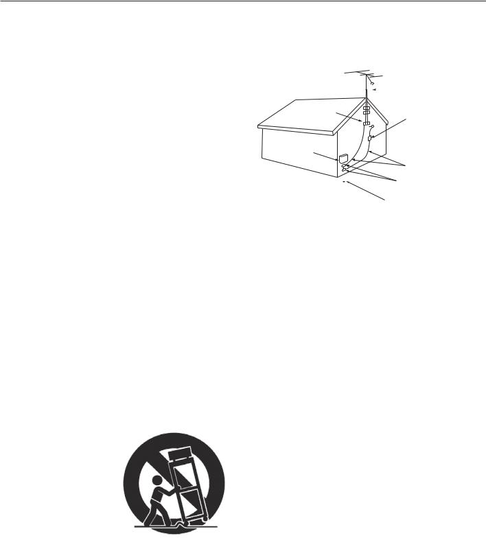
Outdoor Antenna Grounding
If an outside antenna or cable system is connected to the TV, be sure the antenna or cable system is grounded so as to provide some protection against voltage surges and built-up static charges.
Replacement Parts
When replacement parts are required, be sure the service technician has used replacement parts specified by the manufacturer or have the same characteristics as the original part. Unauthorized substitutions may result in fire, electric shock or other hazards.

3
Laser Safety
Laser Safety
•This TV is in compliance with the requirements of IEC 60825-1 Ed. 2(2007).
•This TV is a CLASS 1 laser product. This TV poses no risk to eyes or skin during normal use. An exposure hazard may exist only if the protective housing is removed.
•This TV contains a CLASS 4 laser device, which by itself may be hazardous. However, this TV incorporates a protective housing, optics and electronics such that there should be no exposure to unsafe levels of laser light during normal operation and proper service.
•Do not open this product. No consumer controls inside. Only a trained LASERVUE® technician should service this TV. Please call Mitsubishi for assistance.
-- In the U.S.A. call 1-877-675-2224. -- In Canada call 1-800-450-6487.
Safe Operation
•Always inspect the TV for damage after moving it. If the cabinet or screen is physically damaged, DO NOT connect the TV to an AC outlet.
-- In the U.S.A. call 1-877-675-2224 for assistance. -- In Canada call 1-800-450-6487.
DO NOT power on the TV until it has been repaired by qualified service personnel authorized by Mitsubishi. See “Service” on the next page.
•Caution. Use of controls or adjustments or performance of procedures other than those specified herein may result in hazardous radiation exposure.
•Use external or remote controls to operate the product. Connection to signal sources and power are accomplished through the external connectors.
Damage and Repair
•There are no user serviceable components in this TV. Do not attempt to disassemble any part of the TV.
•If damaged, the device must not be powered on or used until it is repaired by qualified service personnel authorized by Mitsubishi. See “Service” on the next page.
•Under no circumstances shall attempts be made to operate this device without the screen in place or if any portion of the enclosure, including the screen, is cracked, broken, a liquid is spilled onto the TV or is otherwise damaged.
This label is located on the right lower back of the television set.
CAUTION |
|
ATTENTION |
CLASS 4 LASER LIGHT WHEN |
|
LUMIÈRE LASER DE CLASSE 4 - EN CAS |
OPEN AVOID EYE OR SKIN |
|
D’OUVERTURE EXPOSITION DANGERE- |
EXPOSURE TO DIRECT OR |
|
USE AU RAYONNEMENT DIRECT OU |
SCATTERED RADIAITON |
|
DIFFUS DES YEUX OU DE LA PEAU |
|
|
|
This class-4 label and similar service warning labels are located inside the back cover of the television in an area that should not be accessed by the user under any circumstances.
An additional class-4 label is located at the lower front access panel under the front decorative bezel.
This class-4 label is located at the center back of the TV under the outer cover.
In the U.S. call 1(877) 675-2224 for assistance.

For Your Records
Record the model number, serial number, and purchase date of your TV. The model and serial numbers are on the back of the TV. Refer to this page when requesting assistance with the TV.
MODEL NUMBER
SERIAL NUMBER
PURCHASE DATE
RETAILER NAME LOCATION
Installation and Operating Notes
Custom cabinet installation must allow for proper circulation around the television.
NOTE TO CATV SYSTEM INSTALLER: THIS REMINDER PROVIDED TO CALL THE CATV SYSTEM INSTALLER’S ATTENTION TO ARTICLE 820-40 OF THE NEC THAT PROVIDES GUIDELINES FOR THE PROPER GROUNDING AND, PARTICULAR, SPECIFIES THAT THE CABLE GROUND SHALL BE CONNECTED TO THE GROUNDING SYSTEM OF
BUILDING, AS CLOSE TO THE POINT OF CABLE ENTRY PRACTICAL.
Software
not attempt to update the software of this TV with software or USB drives not provided by or authorized by Mitsubishi Digital Electronics America, Inc. (U.S.A.) or Mitsubishi Electric Sales Canada Inc. Non-authorized software may damage the TV and will not be covered by the warranty.
Internal Fans
Internal cooling fans maintain proper operating temperatures inside the TV. It is normal to hear the fans when you first turn on the TV and during quiet scenes while viewing the TV.
Contact Us
For Questions:
U.S.A. www.mitsubishi-tv.com |
Canada www.MitsubishiElectric.ca |
MDEAservice@mdea.com |
support@MitsubishiElectric.ca |
877-675-2224 |
800-450-6487 |
Service
If you are unable to correct a problem with your TV:
U.S.A. 877-675-2224 |
Canada 800-450-6487 |
•DO NOT adjust any controls other than those described in this Owner’s Guide.
•DO NOT remove the protective back cover of your TV.
Customer Support
•This Owner’s Guide is available in electronic format at www.mitsubishi-tv.com.
•To order replacement or additional remote controls, Owner’s Guides, or NetCommand IR emitters:
U.S.A. www.mitsuparts.com |
Canada www.MitsubishiElectric.ca |
800-553-7278 |
800-450-6487 |
In Canada call 1(800) 450-6487 for assistance.

Contents |
|
|
Important Information About Your TV |
|
|
|
Important Safety Instructions. . . . . . . . . . . . . . . . |
2 |
|
Laser Safety. . . . . . . . . . . . . . . . . . . . . . . . . . . . |
3 |
|
Installation and Operating Notes. . . . . . . . . . . . . . |
4 |
1 |
Basic Setup and Operation |
|
|
Package Contents. . . . . . . . . . . . . . . . . . . . . . . . |
6 |
|
Special Features of Your TV. . . . . . . . . . . . . . . . . |
7 |
|
TV Controls and Indicators. . . . . . . . . . . . . . . . . . |
8 |
|
First-Time Power-On.. . . . . . . . . . . . . . . . . . . . . |
11 |
|
Setting Up TV Inputs. . . . . . . . . . . . . . . . . . . . . |
12 |
|
Basic TV Operation. . . . . . . . . . . . . . . . . . . . . . |
14 |
|
Using the TV with a Personal Computer. . . . . . . . |
16 |
2 |
TV Connections |
|
|
Before You Begin.. . . . . . . . . . . . . . . . . . . . . . . |
18 |
|
Cable Management. . . . . . . . . . . . . . . . . . . . . . |
18 |
|
Inputs and Outputs. . . . . . . . . . . . . . . . . . . . . . |
19 |
|
Y Pb Pr Component Video Device. . . . . . . . . . . . |
21 |
|
HDMI Device.. . . . . . . . . . . . . . . . . . . . . . . . . . . . . |
21 |
|
DVI Video Device. . . . . . . . . . . . . . . . . . . . . . . . |
22 |
|
Antenna or Cable TV Service.. . . . . . . . . . . . . . . |
22 |
|
Composite Video Device.. . . . . . . . . . . . . . . . . . |
22 |
|
VCR or DVD Recorder to an Antenna or |
|
|
Wall Outlet Cable. . . . . . . . . . . . . . . . . . . . . . . |
23 |
|
VCR or DVD Recorder to a Cable Box .. . . . . . . . |
23 |
|
A/V Receiver. . . . . . . . . . . . . . . . . . . . . . . . . . . |
24 |
|
A/V Receiver with HDMI Output.. . . . . . . . . . . . . |
24 |
3 |
Using TV Features |
|
|
Selecting an Input .. . . . . . . . . . . . . . . . . . . . . . |
25 |
|
Sleep Timer.. . . . . . . . . . . . . . . . . . . . . . . . . . . |
25 |
|
ChannelView Channel Listings.. . . . . . . . . . . . . . |
26 |
|
Redirecting Audio Output. . . . . . . . . . . . . . . . . . |
26 |
|
Controlling A/V Receiver Sound Volume.. . . . . . . |
26 |
|
Status Display. . . . . . . . . . . . . . . . . . . . . . . . . . |
27 |
|
TV Signals and Display Formats. . . . . . . . . . . . . |
28 |
|
3D Video.. . . . . . . . . . . . . . . . . . . . . . . . . . . . . |
29 |
|
Camera and Music Files. . . . . . . . . . . . . . . . . . . |
31 |
|
Streaming Internet Movies with VUDU. . . . . . . . . |
34 |
|
Introduction to Home-Theater Control. . . . . . . . . |
36 |
4 TV Menus |
|
Main Menu. . . . . . . . . . . . . . . . . . . . . . . . . . . . |
37 |
Menu Navigation. . . . . . . . . . . . . . . . . . . . . . . . |
37 |
Adjust.. . . . . . . . . . . . . . . . . . . . . . . . . . . . . . . |
38 |
Captions. . . . . . . . . . . . . . . . . . . . . . . . . . . . . . |
42 |
Initial.. . . . . . . . . . . . . . . . . . . . . . . . . . . . . . . . |
43 |
Inputs. . . . . . . . . . . . . . . . . . . . . . . . . . . . . . . . |
45 |
Lock.. . . . . . . . . . . . . . . . . . . . . . . . . . . . . . . . |
47 |
5 NetCommand IR Control |
|
About NetCommand IR Control.. . . . . . . . . . . . . |
50 |
IR Emitter Placement. . . . . . . . . . . . . . . . . . . . . |
51 |
Initial NetCommand Setup. . . . . . . . . . . . . . . . . |
52 |
Operating NetCommand-Controlled Devices. . . . |
53 |
6NetCommand IR Control of an A/V Receiver
Controlling an A/V Receiver after
NetCommand Setup.. . . . . . . . . . . . . . . . . . . . 56 Setting Up A/V Receiver Control
Power and Volume. . . . . . . . . . . . . . . . . . . . 57 Automatic Audio or Audio/Video Switching.. . 58
Appendices
Appendix A: Programming the Remote Control. . 64
Appendix B: Bypassing the Parental Lock. . . . . . 71
Appendix C: HDMI Control of CEC Devices. . . . . 73
Appendix D: TV Care.. . . . . . . . . . . . . . . . . . . . 76
Appendix E: Troubleshooting. . . . . . . . . . . . . . . 77
Trademark and License Information. . . . . . . . . . . 84
Mitsubishi TV Software. . . . . . . . . . . . . . . . . . . . 85
Warranty. . . . . . . . . . . . . . . . . . . . . . . . . . . . . . . 88
Index. . . . . . . . . . . . . . . . . . . . . . . . . . . . . . . . . . 92
In the U.S. call 1(877) 675-2224 for assistance.
6 1 Basic Setup and Operation
Package Contents
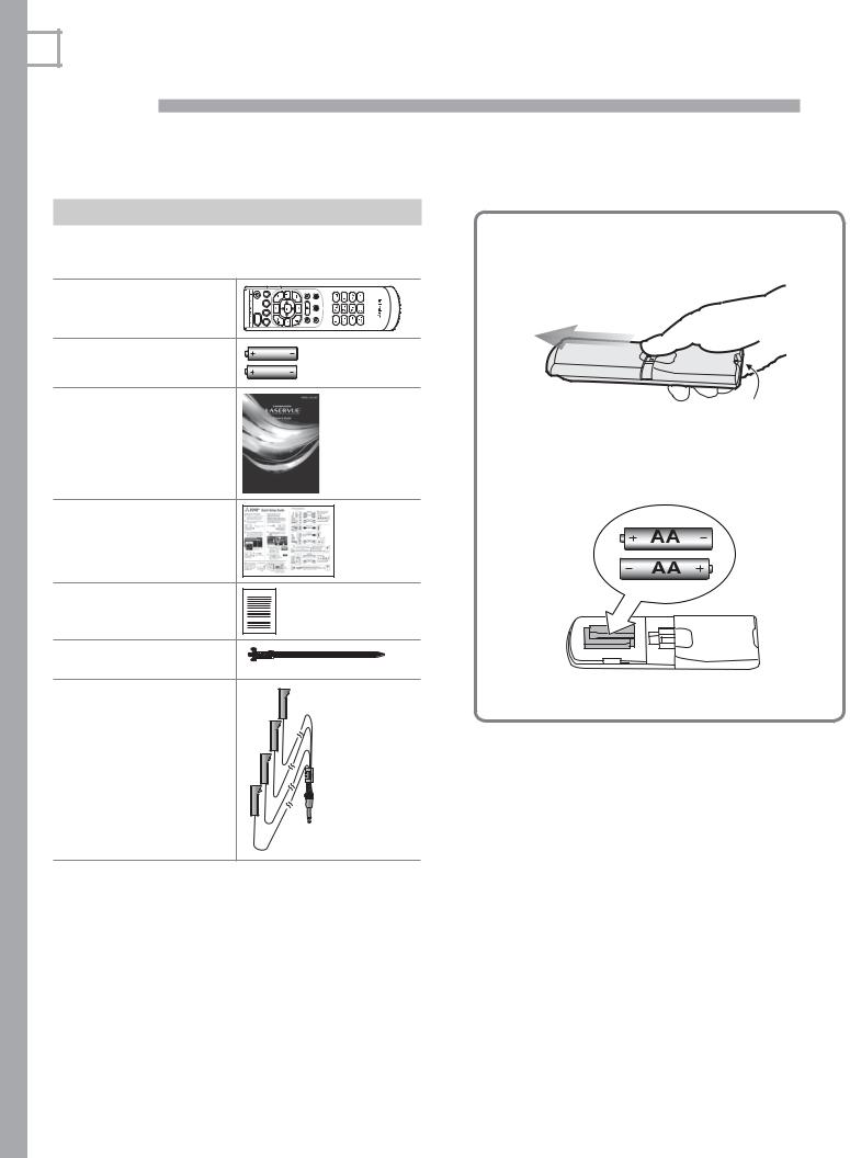
Please take a moment to review the following list of items to ensure that you have received everything.
1. Remote Control
|
ACTIVITY |
2. Two AA Batteries |
AA |
|
AA |
3.Owner’s Guide
4.Quick Setup Guide
5.Product Registration Card
6.Cable Tie
7.L75-A91: Four-ended IR emitter cable
Remote Control Batteries
1. Remove the remote control back cover.
Emitter bulb
2.Load the batteries, making sure the polarities
(+) and (-) are correct. Insert the negative (-) end first.
3. Slide the cover back into place.
In Canada call 1(800) 450-6487 for assistance.

1. Basic Setup and Operation |
7 |
Special Features of Your TV
Welcome to LASERVUE® TV! Mitsubishi has created a new category of television with laser technology. Laser beams provide the widest range of rich, complex colors, along with the most clarity and depth of field. Precise and focused, the purity of laser light far surpasses current high-definition technologies and sets a new standard for premium large-screen television.
Your new high-definition widescreen television has many special features that make it the perfect center of your home entertainment system, including:
1080p High-Definition DLP Display System
Your Mitsubishi HDTV uses Texas Instruments Digital Light Processing™ technology for rear-projection TVs to create the picture you see on screen. All images are displayed at 1080p. The TV uses Plush 1080p® 5G to convert lower-resolution signals to 1080p for display. The TV can also accept 1080p original signals and main-
tain them at 1080p through all processing until displayed.
3D Ready
All Mitsubishi 1080p LASERVUE HDTV’s are 3D Ready. This feature lets you experience the new 3D technologies applied to many recent movies and video games. Immerse yourself in your favorite video game, movie, or sporting event displayed in 3D.
Integrated HDTV Tuner
Your widescreen Mitsubishi LASERVUE HDTV has an internal HDTV tuner able to receive both over-the-air HDTV broadcasts (received via an antenna) and nonscrambled digital cable broadcasts, including nonscrambled HDTV cable programming.
High-Definition Video Inputs
•Component Video Inputs. Also called Y/Pb/Pr inputs, these inputs receive standard analog video formats of 480i, 480p, plus 720p and 1080i highdefinition signals. This provides a high level of flexibility when connecting DVD players/recorders, cable boxes, and satellite receivers.
•HDMI Inputs. These inputs accept digital 480i, 480p, 720p, 1080i, and 1080p video signals plus PCM digital stereo signals. The HDMI™ inputs can also accept a variety of PC signals and resolutions. These inputs support HDMI 1.3 Deep Color (up to 36 bits) and the x.v.Color extended color gamut.
Used with an adapter, these HDMI inputs also accept compatible digital DVI video signals. HDMI inputs provide additional high-performance, high-definition connections for maximum flexibility in your choice of home theater products. The HDMI inputs are HDCP copy-protection compatible.
Easy Connect Auto Input Sensing
Easy Connect™ Auto Input Sensing automatically recognizes when you plug in a device and prompts you to assign a name to it. The TV ignores any unused inputs, so the result is an uncluttered menu where you can easily find and select connected devices by name.
Home-Theater Control
HDMI Control
HDMI devices with Consumer Electronics Control (CEC) capabilities may be compatible with the TV’s HDMI Control feature. Compatible devices can receive control signals through the HDMI connection, allowing the TV’s remote control to operate some functions of these devices.
NetCommand with IR Learning
Model L75-A91. Your Mitsubishi HDTV offers a new level of networking that seamlessly integrates selected older A/V products with new and future digital products. NetCommand® supports IR (infrared) control of products such as VCRs, DVD players, cable boxes, and satellite receivers. NetCommand can “learn” remote control signals directly from many devices, allowing you to create a customized NetCommand-controlled hometheater system.
Internet-Video Ready
Model L75-A91. Built-in VUDU™ connectivity lets you stream high-definition internet video content directly to your TV. Access to VUDU’s fee-based movie service is through menus displayed on the TV. VUDU offers the largest on-demand HD movie selection anywhere, featuring full 1080p and 5.1 surround sound. VUDU allows you to enjoy movies with no store visits, no mailing, no late fees and no subscriptions.
ENERGY STAR®
This is an ENERGY STAR® qualified TV. Products that earn the ENERGY STAR prevent greenhouse gas emissions by meeting strict energy efficiency guidelines set by the U.S. Environmental Protection Agency and the U.S. Department of Energy.
This TV consumes energy in excess of ENERGY STAR guidelines for a powered-down device under the following conditions:
Model TV Condition
L75-A81 TV powered off, Fast Power On mode L75-A91 enabled
L75-A91 TV powered off, External Controller Input enabled
In the U.S. call 1(877) 675-2224 for assistance.
8 |
1. Basic Setup and Operation |
TV Controls and Indicators
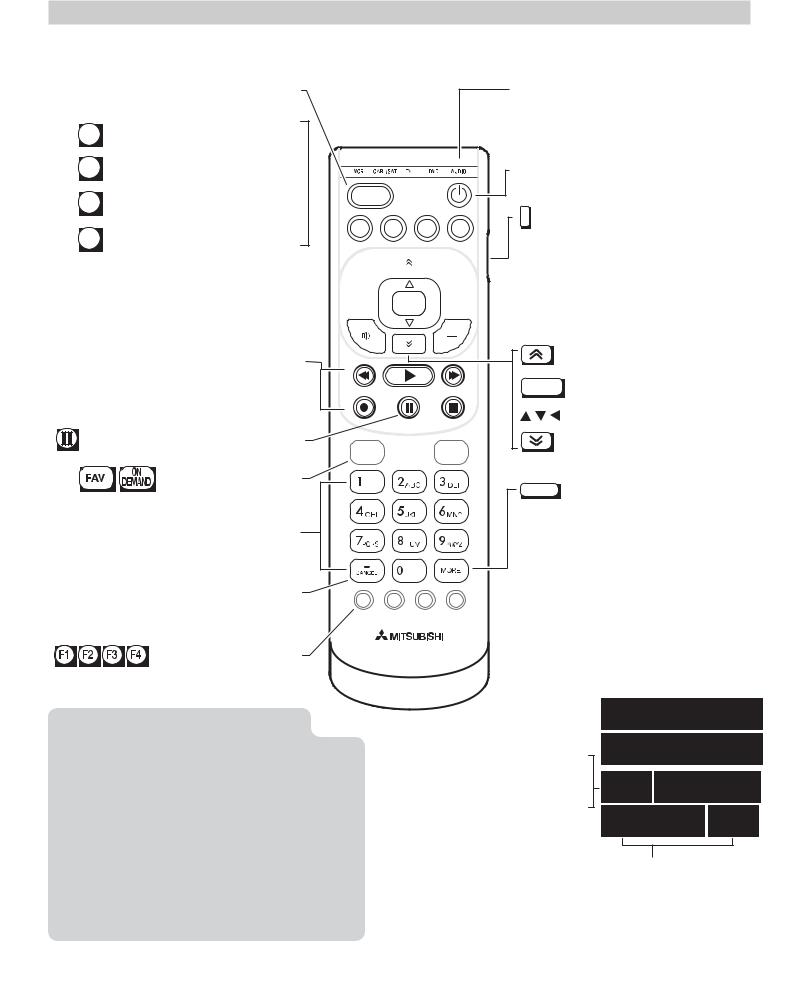
Remote Control
Press to select a TV activity and input. See page 25.
GUIDE ChannelView listings, page 26.
MENU TV main menu, page 37
INFO TV status (page 27) or TV help.
BACK Steps back one menu; clears  the top menu or Status Display.
ACTIVITY
GUIDE |
MENU |
INFO |
BACK |
VCR CABL/SAT TV DVD AUDIO
Control-mode indicator for device type to control. Use the side button to change.
Powers TV on or off
Side button sets the control mode for the type of device to operate. Set mode to TV for normal TV viewing.
Volume Up
MUTE
VOLUME DOWN 
Record/Playback controls for external devices
When remote control is programmed, page 64
HDMI control, page 75
L75-A91: NetCommand, page 55
(Pause) Freezes a broadcast TV picture.
FAV
L75-A91. See page 64. |
Number/letter keys |
Channel tuning, page 14 |
Adds a separator when entering digital |
F1 |
|
channel numbers. Clears some menu entries. |
||
|
||
L75-A91. See page 64. |
|
Note: To operate other audio/video devices using the TV’s remote control:
•See Appendix A, “Programming the Remote Control.”
•For HDMI devices compatible with the TV’s
HDMI Control feature, see Appendix C.
•L75-A91. With NetCommand
-- See page 50 for NetCommand IR “Learning” of device keys.
-- For use of specific keys with NetCom- mand-controlled devices, see “Special Operation Methods,” page 53.


 CHANNEL UP


 LAST. Returns to the previously tuned channel.
 CHANNEL DOWN
ENTER
ON
DEMAND
MORE
PAGE UP
Selects a channel number or menu item.
 Navigation controls
PAGE DOWN
Displays a menu showing additional functions for the number keys.
•For the MORE menu in TV mode, see below.
|
• |
With remote control programmed |
|
|
for another device, the MORE menu |
F2 F3 F4 |
|
is specific to the device. See page |
|
|
64. |
|
• |
For CEC-enabled devices, page 75 |
The
CC Closed captions, page
VIDEO Video adjustments, page
AUDIO Audio adjustments, page
SLEEP Sleep
FORMAT Picture
MORE Clears the MORE menu.
1. Basic Setup and Operation |
9 |
TV Controls and Indicators, continued
TV Control Panel
Buttons on the control panel duplicate some keys on the remote control.
•Refer to left labels when no TV menus are displayed.
•Refer to right labels when using TV menus or after activating a special function.
System Reset
If the TV fails to respond to the remote control, the control-panel buttons, or will not power on/off, perform System Reset. Recent setting changes made before using System Reset may be lost.
To perform System Reset, press and hold the POWER button on the control panel for ten seconds.
Panel-Lock Release
•To release the Panel Lock using the TV control panel, press and hold the ACTIVITY button on the control panel for ten seconds. If the TV is off, press the POWER button to make it power on.
•To activate the Panel Lock, use the Lock menu, page 49.
In the U.S. call 1(877) 675-2224 for assistance.
10 |
1. Basic Setup and Operation |
TV Controls and Indicators, continued
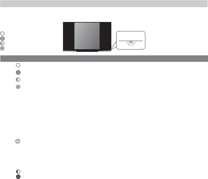
POWER Indicator
Key |
|
|
Off |
POWER |
|
Steady On |
||
|
||
Slow Blinking |
|
|
Fast Blinking |
|
LED Color |
TV Condition |
Additional Information |
|
|
|
None |
TV is powered off. |
Normal operation. |
|
|
|
|
|
|
Green |
TV is powered on. |
Normal operation. |
|
|
|
|
|
|
Green |
TV powered off, auto-on TV Timer is set. |
Normal operation. TV can be turned on at any time. |
|
|
|
Green |
TV power just turned on. |
Normal operation. A picture will appear shortly. |
|
|
|
|
|
|
|
• TV just plugged into AC outlet. |
Wait approximately two minutes for blinking to stop before |
|
• AC just restored after power failure. |
turning on. Normal operation. |
|
|
|
|
• TV is rebooting after power fluctua- |
|
|
tion or receiving abnormal digital |
|
|
signals from a digital channel or |
|
|
digital device. |
|
|
• You have begun the procedure to |
|
|
update software from an authorized |
|
|
flash memory device. |
|
|
|
|
Yellow |
TV is too hot. |
The TV will display a warning message and shut off if it over- |
|
heats. |
|
|
|
|
|
|
• Ambient room temperature may be too high. Turn off |
|
|
the TV and let the room temperature drop. |
|
|
• Clear blocked air vents. Ensure at least a four-inch |
|
|
clearance on all sides of the TV. |
|
|
|
Red |
TV may require service. |
Turn off the TV and unplug the set from the AC power |
|
source. Wait one minute and then plug the set back in. See |
|
|
|
|
|
|
Appendix E. |
|
|
If the LED is still on, contact Mitsubishi to receive Authorized |
|
|
Service Center information: |
|
|
U.S.A. Go to www.mitsubishi-tv.com or call 1-877-675-2224. |
|
|
Canada. Go to www.MitsubishiElectric.ca or call |
|
|
1-800-450-6487. |
|
|
|
In Canada call 1(800) 450-6487 for assistance.
1. Basic Setup and Operation |
11 |
First-Time Power-On
Before You Begin
1.Review the important safety, installation, and operating information at the beginning of this book.
2.Choose a location for your TV.
•Allow at least four inches of space on all sides of the TV to help prevent overheating. Overheating may cause premature failure of the TV.
•Avoid locations where light may reflect off the screen.
•See the stand requirements on page 1.
3.Install the batteries in the remote control.
4.Plug the TV into an AC power outlet.
TV Tips
Turning the TV On or Off
•Point the remote control at the front of the TV and press the POWER button.
•Press the POWER button on the TV control panel.
Controlling Sound Volume
•Press VOLUME UP/VOLUME DN to adjust the sound level from the TV speakers.
•See also “Controlling A/V Receiver Sound Volume” on page 26.
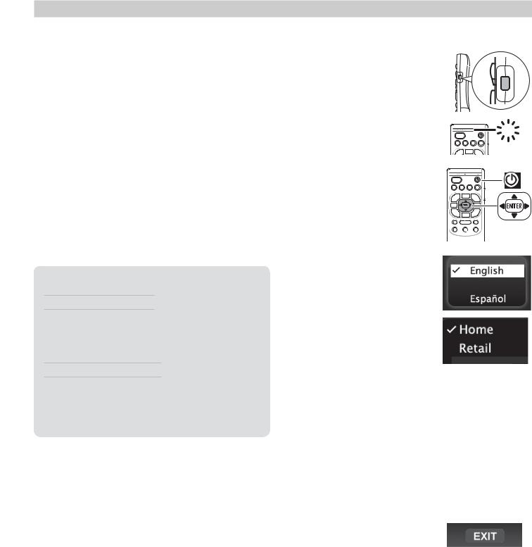
Power-On
1.Confirm that the remote control is in TV mode.
•Press the side button once to light the mode indicator and confirm that TV mode is active.
•To change, press the side button additional times to activate TV mode.
2.Aim the remote control
at the TV and press the POWER key  . Wait for the
Welcome screen.
3.Press if you wish to change the menu language to Español.
Press to move to the
Home/Retail selections. Here you can choose a picture mode suited to your viewing conditions.
TV
GUIDE MENU INFO BACK
GUIDE MENU INFO BACK
•Mitsubishi recommends the Home setting. The Home setting selects the Brilliant Picture Mode.
•The Retail setting selects the Super Brilliant Picture Mode. The Super Brilliant Picture Mode is designed to compensate for the harsh, bright lighting used in retail settings and is not recommended for home use. Prolonged use of the Super Brilliant Picture Mode will age the lasers faster, reducing picture brightness as the TV ages.
•For more on Picture Modes, see page 38.
5.Press to highlight EXIT. Press ENTER to clear the menu.
In the U.S. call 1(877) 675-2224 for assistance.
12 |
1. Basic Setup and Operation |
Setting Up TV Inputs
Using the ANT (Antenna) Input
If using an antenna or direct cable service (no cable box), connect the incoming coaxial cable to the TV’s ANT input. Refer to page 22.
You must save channels to memory with a channel scan to enable reception of all available high-definition and standard-definition digital channels. The channel scan will search for channels available locally. If you skip this step, the TV can receive only analog channels.
Memorizing Channels with Channel Scan
For the ANT input
To start channel memorization
1.Power on the TV.
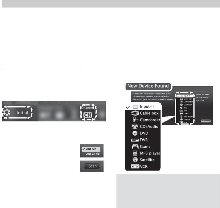
2.Press MENU and open the Initial > Channel menu.
Start channel memorization from the Initial > Channel menu.
3.Press ENTER to enter the menu.
4.Select Ant Air if connected to an over-the-air antenna. Select Ant Cable for direct cable.
5.Highlight Scan and press ENTER. Channel memorization may take up to 15 minutes to complete.
To stop channel memorization before completion, press CANCEL.
Use the Initial > Channel > Edit menu (page 44) for additional channel options, such as adding or deleting channels from memory.
Setting Up Other Inputs
1.Connect your devices to the TV, making note of which TV input jack is used for each device. See “TV Connections,” page 18, for recommendations.
2.Power on the devices to ensure detection.
3.Power on the TV.
The TV will display the New Device Found screen for each new connection it detects Learn more about Auto Input/Auto Output Sensing on the opposite page.
4.Select the device type from the list on screen.
Sample New Device
Found screen.
Important Note for NetCommand IR Users
L75-A91. Be sure to select the correct device type here. Although you can change the device type later in the Inputs > Name menu, any “learned” NetCommand IR codes will be erased when you make the change.
5.L75-A91. You can perform NetCommand IR “learning” after selecting the device type or at a later time when convenient. To perform now, high-
light NetCommand and press ENTER. See “Initial NetCommand Setup,” page 52 or “Setting Up A/V Receiver Control,” page 57.
6.Press BACK to close the New Device Found screen. The TV will then display the New Device Found screen for the next connection it finds.
In Canada call 1(800) 450-6487 for assistance.
1. Basic Setup and Operation |
13 |
Setting Up TV Inputs, continued
About Auto Sensing
This TV’s Easy Connect™ Auto Sensing feature detects most connections automatically. The exceptions are:
•A connection on the ANT input
•An HDMI device that is powered off. Power on the device to ensure detection.
Auto Input/Auto Output Sensing for Most Devices
When you first connect a device, the TV will:
a.Detect the connected device and automatically switch to it.
b.Prompt you to identify the device type.
c.L75-A91. Prompt you to perform NetCommand set-up for the device, if available.
d.Repeat these steps for other newly detected devices.
When You First Connect a Device
•Most Device Types. Select the device type from the on-screen list. The device type you select here will appear as a device icon in the Activity menu.
•A/V Receiver
-- The TV can detect audio connections on the
DIGITAL AUDIO OUTPUT jack (orange) and the right (red) AVR AUDIO OUTPUT jack.
-- For an HDMI A/V receiver, select AVR from the list of device types if the A/V receiver is not recognized automatically.
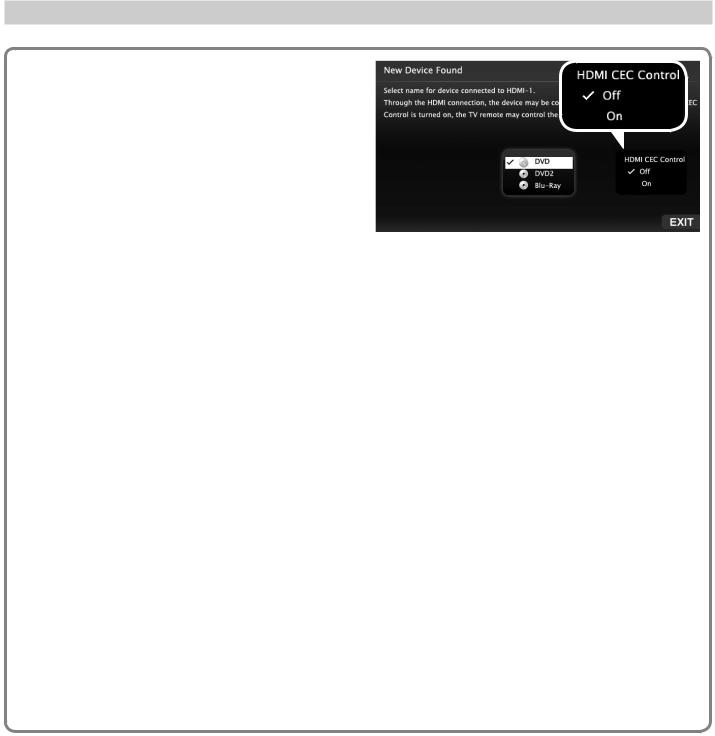
•HDMI CEC Devices Compatible with the TV’s HDMI Control Feature. Compatible CECenabled HDMI devices are often recognized automatically by the TV. HDMI Control may allow you to control some functions of a CEC-enabled device. See Appendix C, “HDMI Control of CEC Devices.”
New Device Found screen for a device with HDMI control enabled. Select On to enable the TV’s CEC control of the device. In some cases, as in the example above, you will also be prompted to select a device name.
Tips on Auto Sensing
•Choose a different name for each input.
•The antenna input (ANT) is never detected, although you can turn off the unused antenna input in the Inputs > Name menu.
•Change the device type displayed in the Activity menu by using the Inputs > Name menu (page 45).
•L75-A91. Any “learned” NetCommand IR codes will be erased if you change the device type in the Inputs > Name menu.
Reactivating Auto Input Sensing for an HDMI Input
When you disconnect an HDMI device, Auto Input Sensing is disabled until you perform these steps.
1.Disconnect the HDMI device.
2.Delete the removed HDMI device in the Inputs > Name menu (see “Removing an HDMI Device,” page 75).
3.Connect the new device and the New Device Found screen will display.
In the U.S. call 1(877) 675-2224 for assistance.
14 |
1. Basic Setup and Operation |
Basic TV Operation
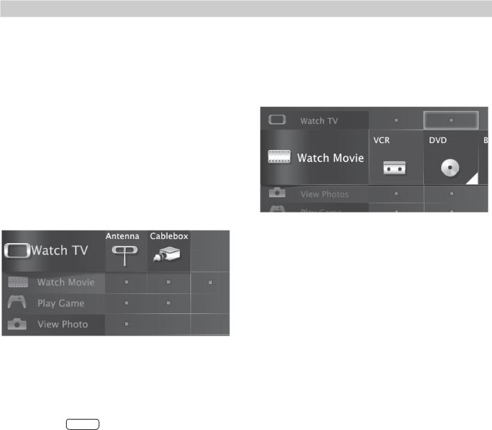
Selecting an Input to Watch
1.Press ACTIVITY.
2.Press and
and to highlight an input.
3.Press ENTER to switch to the input.
Watching Broadcast TV
TV Connected to an Antenna, Direct Cable, Cable Box, Set-Top Box, or Satellite Receiver
1.Press ACTIVITY.
2.Press and
and to select a broadcast source. If you named devices during Auto Input Sensing, select an input from the Watch TV group. Note: Your TV may have only one group (Watch TV).
Note: For more about the Activity menu, see page 25.
Activity menu, antenna input selected
3.Tune to a channel on the ANT input using any of these methods.
•Enter the channel number using the number keys on the remote control and press ENTER.
For a two-part digital channel, such as 3-1, |
||
press 3 |
— |
1 to enter a dash (separator). |
CANCEL |
||
•Press CHANNEL UP /CHANNEL DN (+/–) to change channels one channel at a time.
•Press  (LAST) to switch back to the previously tuned channel.
•Antenna or Direct Cable Only. Press GUIDE to display ChannelView channel listings, highlight a channel number, and press ENTER to tune.
Note: Program information is provided by broadcasters and may not be available in all areas.
Watching DVDs or Videos
TV Connected to a DVD Player, DVR, or VCR
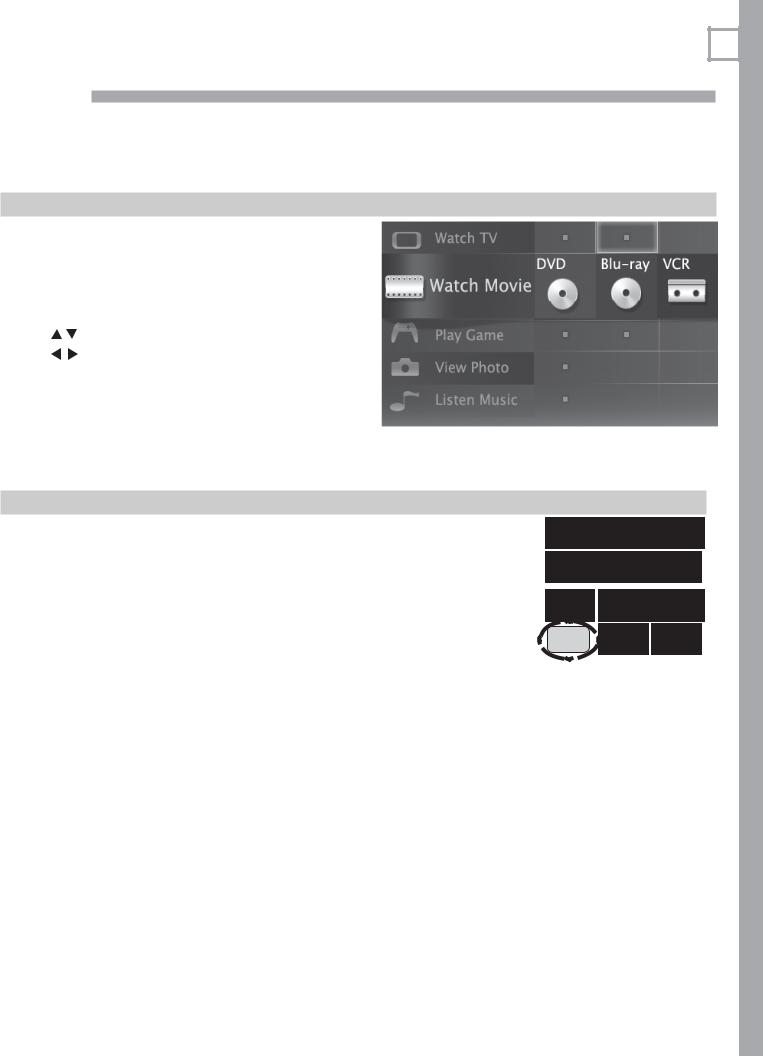
Press ACTIVITY and select a movie source from the Activity menu. If you named devices during Auto Input Sensing, select the input from the Watch Movie group.
Activity menu, DVD input selected
In Canada call 1(800) 450-6487 for assistance.

1. Basic Setup and Operation |
15 |
Basic TV Operation, continued
Making Picture Adjustments
1.To get the best picture under different viewing conditions, set the Picture Mode before changing other video settings. See page 38 for more.
a.Press MORE.
b.Press 8 (VIDEO).
c.Press 
 to make one of these Picture Mode selections:
Name |
|
When to Use |
Super |
|
Under harsh retail lighting; not |
|
||
Brilliant |
|
recommended for home use |
|
|
|
Brilliant |
|
Under bright light |
|
|
|
Game |
|
With gaming consoles |
|
|
|
Bright |
|
For most daytime viewing |
|
|
|
Natural |
|
For most nighttime viewing |
|
|
|
Cinema |
|
For recreating theater colors |
|
|
|
2.Press 
 to display the name of the next adjustment you want.
3.Press 
 to make the adjustment.
Additional picture adjustments are described on pages 40 and 41.
Audio Settings
Changing the Audio Output
To switch audio output from the internal TV speakers to a connected external sound system or headphones:
1.Press MORE.
2.Press 9 (AUDIO).
3.Press 
 until the Speakers option is displayed. The Speakers option will display only if a connection has been detected on one of the TV’s audio outputs.
4.Press  to switch between TV and either AV Receiver or Headphones.
Changing Audio Settings
1.Press MORE.
2.Press 9 (AUDIO).
3.Press 
 to display the name of the adjustment you want.
4.Press 
 to change the setting.
Other TV Features
•Activate Audio Lock to control your sound system with the TV’s remote control left in TV mode. See page 65.
•To set the TV Clock see page 43. Set the TV Clock if you plan to use the TV Timer (page 43) or ChannelView (page 26) features.
•To set parental controls, see the Lock menu, page 47.
Note: L75-A91. To set parental controls for VUDUmenu.™ service, use the VUDU Info & Settings
•To change the input names that appear in the Activity menu, see Inputs > Name options, page 45.
•3D Video. See page 29.
•To program the remote control to operate other A/V devices, see Appendix A, “Programming the Remote Control,” page 64.
•To control compatible devices using HDMI CEC control, see Appendix C, “HDMI Control of CEC Devices,” page 73.
•To view still and moving digital camera images on the TV, see “Camera and Music Files,” page 31.
•L75-A91. To control A/V devices with NetCommand, see chapter 5, “NetCommand IR Control for Most Devices” on (page 50).
•L75-A91. See page 34 for internet video streaming with VUDU™.
Other Information
TV Care
•Remote Control. See “Care of the Remote Control” on page 76
•General Cleaning. See “Cleaning Recommendations,” page 76.
Assistance
•For basic troubleshooting, see Appendix E, page 77.
•For service, and product support, see page 4.
•For warranty information, see the TV warranty on page 88.
In the U.S. call 1(877) 675-2224 for assistance.
16 |
1. Basic Setup and Operation |
Using the TV with a Personal Computer
Connecting a Computer to the TV
Use one of the connection methods listed below based on your computer’s video output.
Computer |
Video Connection |
Audio |
|
Video Output |
Connection |
||
|
|||
|
|
|
|
Digital DVI |
DVI-to-HDMI cable |
Stereo audio |
|
|
or an HDMI cable |
cables |
|
|
with an HDMI-to- |
|
|
|
DVI adapter |
|
|
|
|
|
|
|
Note: If the computer’s audio output |
||
|
is a single mini jack, a mini audio-to- |
||
|
RCA-male “Y” adapter cable is also |
||
|
required. |
|
|
|
|
|
|
HDMI |
HDMI-to-HDMI |
No additional |
|
|
cable |
audio connec- |
|
|
|
tion is required. |
|
|
|
|
|
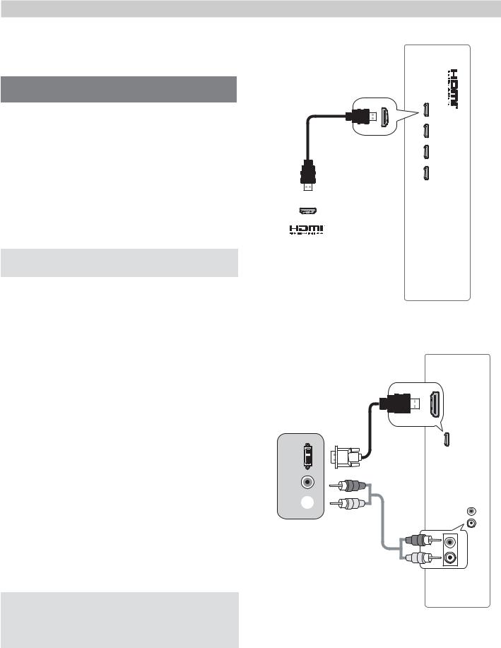
IMPORTANT
This TV accepts digital computer signals only.
1.Connect the computer’s digital signal output to one of the TV’s HDMI jacks. See the connection diagrams for the method suited to your equipment.
2.Connect the computer’s audio output using one of these options:
•For digital DVI signals, connect analog left/right audio to the TV’s DVI/PC INPUT AUDIO jacks.
•For HDMI signals, no additional audio connection is required.
3.Power on the TV and computer. The TV will detect the connection and display the New Device Found screen.
4.In the New Device Found screen, press 
 to highlight PC in the list of device types. It is important to use the name PC so that the TV processes the computer signal correctly.
5.Press BACK to close the New Device Found screen.
TV panel
Computer with
HDMI output
An HDMI-to-HDMI connection carries all video and audio on a single cable.
TV
DVI
OUT
R
AUDIO
L 
Computer with DVI and analog stereo outputs
INPUT DVI/PC
L R
INPUT DVI/PC
L R
Note: If your computer provides digital audio output (coaxial or optical), you can connect it directly to a digital A/V receiver and bypass the TV.
In Canada call 1(800) 450-6487 for assistance.
A DVI connection from a personal computer requires a separate audio connection.
1. Basic Setup and Operation |
17 |
Using the TV with a Personal Computer, continued
Computer Video Adjustments
1.Power on the computer.
2.Select PC from the Activity menu. To do this, press ACTIVITY to open the Activity menu, move the highlight to the PC icon, and press ENTER.
Tip
Set the computer’s screen saver to display a pattern after several minutes of inactivity. This acts as a reminder that the TV is powered on.
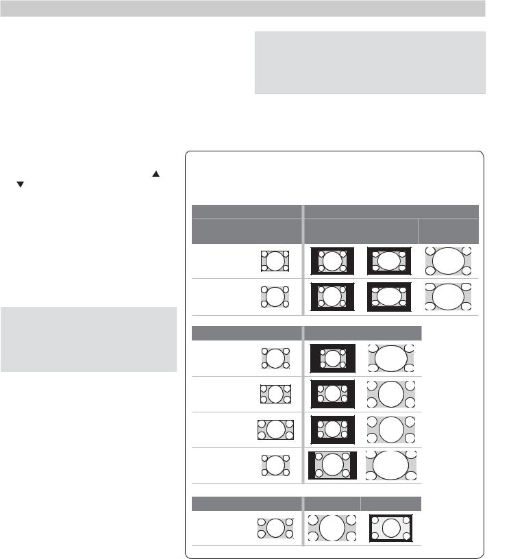
3.Working from the computer, change the resolution of the computer image. View the computer image on the TV and maximize the computer resolution while maintaining a suitable aspect ratio for the image.
4. Perform TV video adjustments. Press |
Computer Display Formats |
|
||
MORE then press 8 (VIDEO). Use |
|
|
|
|
to cycle through video-adjustment |
|
|
|
|
options. |
|
|
|
|
5. Press MORE then press 0 (FORMAT |
Computer Signal |
As Displayed on TV Screen |
||
repeatedly to find the picture format |
Original Format |
4 X 3 |
16 X 9 |
|
(aspect ratio) best suited to the image |
||||
Standard |
Standard |
|||
See the chart on this page showing |
|
|||
|
|
|
||
how different computer resolutions |
VGA |
|
|
|
can be displayed on the TV. |
640 X 480 |
|
|
|
SVGA
Distortion in Computer Images
Computer images may show distortion when viewed on the TV, e.g., lines that should be straight may appear slightly curved.
Image Resolution
Your Mitsubishi TV can display the resolutions shown in the chart from standard VGA (640 x 480) through 1920 x 1080 signals at a refresh rate of 60 Hz.
In most cases, the computer will select the best resolution match to display on the TV. You can override this setting if you wish. Refer to your computer operating system’s instructions for information on changing the screen resolution.
You may need to restart the computer for changes to take effect.
Original Format |
Standard |
Zoom |
XGA
1024 X 768
PC 720p
1280 X
WXGA 1360 X 768
SXGA
Original Format |
Standard |
Reduce |
PC 1080p
1920 X 1080
In the U.S. call 1(877) 675-2224 for assistance.
18 2 TV Connections
Before You Begin
Auto Input Sensing
The TV’s Auto Input Sensing feature automatically recognizes most connections and prompts you to identify the type of device connected. See page 13 for more on Auto Input Sensing.
Connection Types
Use the connection types available on your input devices that will give the best video quality. For example, choose HDMI over component video, and choose component video over composite video.
Picture Quality
For best picture quality, route signals directly from the input device to the TV whenever possible.
Surround Sound
For best surround sound audio quality, route audiosignal cables or HDMI cables from the source device directly to your A/V receiver or sound system.
IMPORTANT
Accessory items such as cables, adapters, splitters, or combiners required for TV connections are not supplied with the TV. These items are available at most electronics stores.
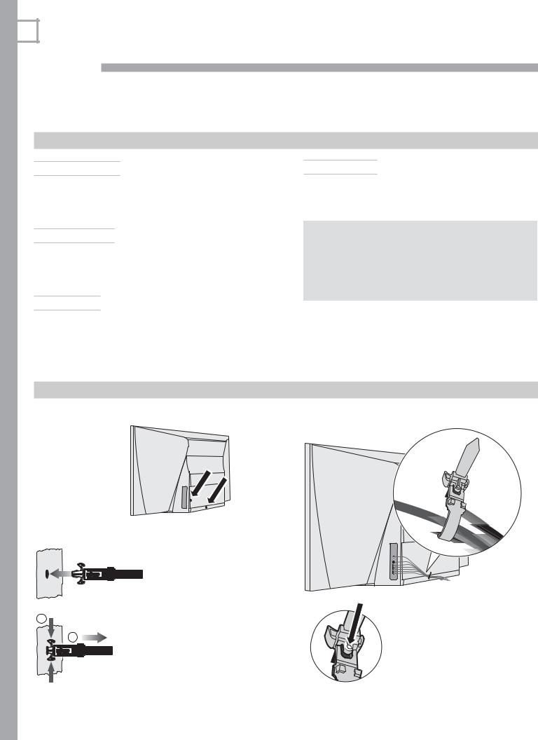
Cable Management
Install the cable tie (supplied) in one of the mounting holes on the back.
Lock the cable tie in place by pushing the end into the mounting hole.
1
2
To remove the cable tie, squeeze the side tabs and pull out.
Sample cable routing. Secure the cable bundle with the release tab facing out.
Press the release tab to loosen the cable tie.
In Canada call 1(800) 450-6487 for assistance.
2. TV Connections |
19 |
Inputs and Outputs
1. ANT (Antenna)
Connect your main antenna or direct cable service (no cable box) to ANT. The ANT input can receive digital and analog over-the-air channels from a VHF/UHF antenna or non-scrambled digital/analog cable source.
2. 3D GLASSES EMITTER
Use this jack for the special IR emitter supplied with 3D glasses. The emitter will send a signal that
synchronizes your 3D glasses with the screen display. See page 29
3. IR–NetCommand Output/External Controller Input
Connect IR emitters to this jack to send control signals to external IR-controlled devices. This jack can also serve as the input for an external controller.
4. Y Pb Pr (Component Video)
Connect devices with component video outputs to this jack. Use the adjacent INPUT 1/INPUT 2 audio R and L jacks if you wish to send audio to the TV.
5. Video (Composite Video)
Connect a VCR, DVD player, standard satellite receiver, or other A/V device to the TV. Use the adjacent INPUT 1/INPUT 2 audio R and L jacks if you wish to send audio to the TV.
USBa and LAN jacks
offered on L75-A91. |
|
14 |
USBa (power |
only, page 34) |
|
13 |
LAN (page 34) |
11 |
USB (page 31) |
1 |
|
2 |
232C-RS |
HDMI |
|
3 |
|
RS-232 control jack is offered on L75-A91.
12 RS-232
7 |
HDMI (page 21) |
|
HDMI 4 offered |
4 |
on L75-A91. |
6. L/R (Left/Right Analog Stereo Inputs)
Use with INPUT 1/INPUT 2 video inputs, items |
6 |
|
|
4 and 5 . |
|
|
|
|
VIDEO |
|
|
IR-NetCommand |
(composite video, |
5 |
|
page 23) |
|
||
Output/External |
|
|
|
|
|
|
|
Controller offered |
Y Pb Pr |
|
|
on L75-A91. |
(component video, |
4 |
|
|
page 21) |
|
|
|
IR–NetCommand |
|
-IR Controller |
|
Output/External Con- |
3 |
|
|
troller Input (page 51) |
|
Output/External Input |
|
|
|
|
|
3D GLASSES EMITTER |
|
NetCommand |
|
2 |
|
|
|
(page 29) |
|
|
|
|
|
|
R |
OUTPUT |
DIGITAL |
|
AUDIO |
|
L |
DVI/PC |
|
R |
VIDEOY/ |
INPUT |
|
L |
|
AVR |
Pb |
R |
AUDIO |
|
Pr |
OUTPUT |
|
L |
INPUT 1 |
INPUT 2 |
|
GLASSES EMITTER |
|
3D |
ANT (page 22) 1 |
ANT |
DIGITAL Audio
8OUTPUT
(page 24)
DVI/PC INPUT
9(audio input, page 22)
AVR Audio
10OUTPUT
(page 24)
In the U.S. call 1(877) 675-2224 for assistance.

20 |
2. TV Connections |
Inputs and Outputs, continued
7. HDMI™ Inputs (High-Definition Multimedia Interface)
The HDMI inputs support uncompressed standard and high-definition digital video formats and PCM digital stereo audio.
Mitsubishi recommends you use category 2 HDMI cables, also called high-speed HDMI cables, to connect HDMI 1.3 source devices. High-speed category 2 cables bring you the full benefits of Deep Color and x.v.Color.
These HDMI inputs can also accept digital DVI video signals. To connect a device’s DVI output to the TV’s HDMI input, use an HDMI-to-DVI adapter or cable plus analog audio cables. Connect the analog audio cables to the DVI/PC INPUT AUDIO jacks on the TV to receive left and right stereo audio from your DVI device.
Use the HDMI inputs to connect to CEA-861 HDMI compliant devices such as a high-definition receiver or DVD player. These inputs support 480i, 480p, 720p, 1080i, and 1080p video formats.
The TV’s HDMI inputs are compatible with many DVI-D and HDMI computer signals.
These inputs are HDCP (High-Bandwidth Digital Copy Protection) compliant.
8. DIGITAL AUDIO OUTPUT
This output sends Dolby Digital or PCM digital audio to your digital A/V surround sound receiver. Incoming
analog audio is converted by the TV to PCM digital audio. If you have a digital A/V receiver, in most cases this is the only audio connection needed between the TV and your A/V receiver.
HDMI Cable Categories
HDMI cables are available as Standard and High-Speed types.
•High-Speed HDMI Cables (also called Category 2 Cables). Newer DVD players, video games, and set-top boxes require High-Speed HDMI cables, suitable for clock frequencies up to 340 MHz or data rates of up to 10.2 gigabits per second. Use high-speed cables for 1080p HD signals carrying extended color encodings (i.e., 30 or more bits, also called Deep Color). HighSpeed HDMI cables are also suitable for standard HDTV signals.
•Standard HDMI Cables (also called Category 1 Cables). Standard HDMI cables may be unmarked. They are suitable for standard HDTV 720p, 1080i, and 1080p signals with 8-bit color depth. Use category 1 cables for clock frequencies up to 74.25 MHz or data rates of up to 2.23 gigabits per second.
In Canada call 1(800) 450-6487 for assistance.
9. DVI/PC INPUT AUDIO
When connecting a DVI device to one of the TV’s HDMI inputs, use these jacks for left and right analog audio.
10. AVR AUDIO OUTPUT
Use AVR AUDIO OUTPUT to send analog audio of the current program to an analog A/V surround sound receiver or stereo system. Digital audio from digital channels and HDMI devices is converted to analog audio by the TV for output on this jack. This is the only audio connection needed to the TV if using an analog A/V receiver or stereo system.
Headphones. These jacks can also be used for headphones that accept standard line level audio signals. An adapter may be required.
11. USB
The TV can read JPEG photo files and mp3 music files from a USB device connected to the USB port.
12. RS-232C
L75-A91. Use the RS-232C interface to receive control signals from compatible home-theater control devices. See www.mitsubishi-tv.com for a list of control signals for this interface.
13. LAN
L75-A91. Use the LAN Ethernet jack for streaming internet video to the TV. See page 34 for setup. Visit www.VUDU.com for details about VUDU™ service.
14. USBa
L75-A91. Standard USB 5-volt, 500-milliamp power output you can use to supply power to an accessory device. For use with the VUDU wireless adapter, see page 34.
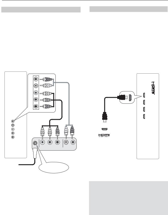
Y Pb Pr Component Video Device
HDTV Cable Box, Satellite Receiver, DVD/
Blu-ray Player
If your source device has an HDMI output, use the connections for HDMI devices described on this page instead of Y Pb Pr component video.
Required:
1.RCA-type component video cables
2.Left/right analog audio cables.
Note: To hear digital surround sound, connect the digital audio output from the device directly to your digital A/V receiver.
R
L |
2. |
VIDEO Y/ |
|
Pb |
|
Pr |
|
|
1. |
R |
TV |
|
panel |
L |
|
VIDEO Y/ |
|
Pb |
|
Pr |
|
AUDIOR
Any device with component video output
CABLE IN or Incoming from SATELLITE IN cable service or
satellite dish
2. TV Connections |
21 |
HDMI Device
HDTV Cable Box, Satellite Receiver, DVD/ Blu-ray Player
Required: HDMI-to-HDMI cable.
Connect an HDMI cable from the TV back panel to the HDMI device output. HDMI devices provide video and audio through the single cable.
Mitsubishi recommends you use category 2 (highspeed) HDMI cables to connect HDMI 1.3 source devices. High-speed category 2 cables bring you the full benefits of Deep Color and x.v.Color. See “HDMI Cable Categories” on the opposite page for more on HDMI cable types.
TV panel
Any device with
HDMI output
IMPORTANT
HDMI and Audio Signals
Digital Surround Sound: The TV’s HDMI inputs can receive digital stereo audio signals only. To hear digital surround sound from an HDMI device, connect the device’s HDMI or digital audio output directly to your A/V receiver. See the Owner’s Guides for those devices for instructions.
In the U.S. call 1(877) 675-2224 for assistance.
22 |
2. TV Connections |
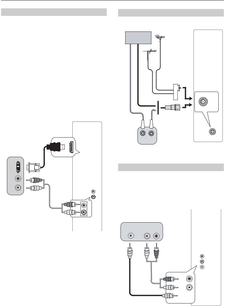
DVI Video Device
Cable Box, Satellite Receiver, DVD Player
Connect DVI devices (digital only) to the TV’s HDMI input jacks.
Required:
1.DVI-to-HDMI cable or DVI/HDMI adapter and HDMI cable
2.Analog stereo audio cables
If you are using a DVI/HDMI adapter, it is important to connect the adapter to the DVI device for best performance.
Some devices require connection to an analog input first in order to view on-screen menus and to select DVI as the ouput. Please review your equipment instructions for DVI connectivity and compatibility.
Note: The HDMI connection supports copy protection (HDCP).
TV panel
|
1. |
|
DVI |
|
|
OUT |
|
|
R |
|
|
|
|
DVI/PC |
|
|
R |
|
|
INPUT |
Digital DVI |
|
L |
2. |
|
|
device |
R |
|
|
|
DVI/PC |
|
|
INPUT |
|
|
L |
Antenna or Cable TV Service
Connect the incoming cable to the TV’s ANT input.
Cable TV
service UHF/VHF antenna
Direct cable (no cable box)
or
Older cable
box IN OUT
300-ohm-to75- ohm combiner (side view)
or
Not recommeded. |
|
|
Other connection |
|
|
types provide better |
|
|
quality audio and |
TV panel |
|
video. |
||
|
ANT
Composite Video Device
VCR or other device with composite video output
Required:
1.Composite video cable (usually yellow)
2.Analog stereo audio cables.
VCR or other device with composite video output
COMPOSITE |
L |
R |
VIDEO OUT |
AUDIO OUT |
|
|
|
|
1.
In Canada call 1(800) 450-6487 for assistance.
2.
TV panel
 VIDEO Y/ L R
VIDEO Y/ L R
2. TV Connections |
23 |
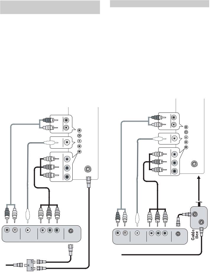
VCR or DVD Recorder to an Antenna or Wall Outlet Cable
Required:
1.Video cables
1a. Component video cables (red/blue/green) or
1b. Composite video cable (usually yellow)
2.Left/right analog audio cables.
3.Two-way RF splitter
4.Two coaxial cables
Note:
•Use composite video only if component video or HDMI are unavailable. For an HDMI connection between the TV and recorder, see page 21.
•If your recording device has an analog-only tuner, you must use a digital converter box to enable recording of digital broadcasts.
VCR or DVD Recorder to a Cable Box
Required:
1.Video cables
1a. Component video cables (red/blue/green) or
1b. Composite video cable (usually yellow)
2.Left/right analog audio cables.
3.One coaxial cable
4.Video and audio cables required to connect the TV to the cable box.
Notes: Use composite video only if component video or HDMI are unavailable. For an HDMI connection between the TV and recorder, see page 21.
When using this connection configuration, it is possible to view live cable programs through the recording device. For best picture quality always view live cable programs directly from the TV input connected to the cable box device.
|
|
|
|
|
|
|
|
R |
|
|
|
|
|
R |
|
|
|
|
|
|
|
2. |
|
|
|
|
2. |
|
|
L |
|
|
|
|
L |
|
|
|
|
|
|
|
|
|
|
|
|
|
|
|
|
|
L |
|
|
|
|
VIDEO Y/ |
VIDEO Y/ L |
|
|
|
VIDEO Y/ |
Pb VIDEO Y/ |
|
|
|
|
|
Pb |
|
|
|
|
Pr |
|
|
|
|
|
Pr |
|
|
|
|
|
|
|
|
|
|
|
|
|
|
Pb |
|
ANT |
|
|
|
Pb |
|
ANT |
|
|
|
|
|
|
|
|
|
|
|
|
|
Pr |
|
|
|
|
|
Pr |
|
|
|
|
|
TV |
|
|
|
|
|
TV |
|
|
|
Audio and video |
4. |
|
|
|
|
|
|
|
1b. |
or |
|||
|
|
|
|
|
|
1a. |
from cable box |
|
||
|
1b. |
or |
1a. |
|
|
|
|
|
directly to TV, |
|
|
|
|
|
|
preferably HDMI or |
|
||||
|
|
|
|
|
|
|
|
|
componenet |
|
|
|
|
|
|
2. |
|
|
|
connections. |
|
|
|
|
|
|
|
|
|
|
|
|
|
|
|
|
|
|
|
|
|
3. |
OUT |
|
|
|
|
|
|
|
|
|
|
|
|
|
|
|
|
|
|
|
|
IN |
|
R |
COMPOSITE |
COMPONENT |
ANTENNA |
R |
|
|
|
|
|
|
AUDIO OUT |
|
|
VIDEO OUT |
IN |
COMPOSITE |
COMPONENT |
ANTENNA |
|
||
|
|
|
|
|
AUDIO OUT |
|
|
VIDEO OUT |
IN |
|
DVD Recorder or VCR |
DVD Recorder or VCR |
|
3. |
RF Splitter |
4. |
Incoming cable |
|
|
||
|
|
|
4. |
Incoming |
|
|
|
cable |
|
|
|
In the U.S. call 1(877) 675-2224 for assistance.
24 |
2. TV Connections |
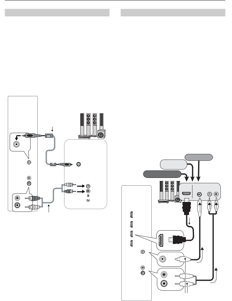
A/V Receiver
Most setups require either a digital audio cable or analog stereo audio cables. To send audio from TV channels received on the ANT input or devices connected directly to the TV, you must use one of the connections shown below. Usually, only one of these connections is required.
The TV makes all audio available in digital and analog formats:
•Analog audio coming into the TV is available as output in digital stereo format on the DIGITAL AUDIO OUTPUT jack.
•Digital incoming audio is available as analog output on the AVR AUDIO OUTPUT L and R jacks.
Digital coaxial cable (for a digital A/V receiver)
OUTPUT |
DIGITAL |
AUDIO |
|
DIGITAL OUTPUT |
|
AUDIO |
|
AVR |
TV |
R |
|
AUDIO |
|
OUTPUT |
|
L |
|
OUTPUT AUDIO AVR
L R
Stereo analog cables (for an analog A/V receiver)
COAXIAL
INPUT
A/V receiver back panel
Note:
•On rare occasions, an HDMI signal may be copy-restricted and cannot be output from the TV as a digital signal. To hear these copy-
protected signals through the A/V receiver, use the connection for an analog A/V receiver.
•Check the A/V receiver’s Owner’s Guide for information concerning use of the digital input and switching between digital sound and analog stereo sound from the TV.
In Canada call 1(800) 450-6487 for assistance.
A/V Receiver with HDMI Output
Required: One HDMI-to-HDMI cable
Optional: One digital coaxial audio cable or analog stereo audio cables
This option allows you to view content from devices connected to an A/V receiver. The A/V receiver can send audio and video to the TV over a single HDMI cable.
•In addition to the HDMI connection, you can use an audio connection from one of the TV’s audio outputs. The optional audio connection allows you to hear, through the A/V receiver, devices connected to the TV only, e.g., an antenna on the ANT input.
•You may be able to use the TV’s remote control (in TV mode) to operate connected CEC-enabled HDMI devices. See Appendix C, page 73.
•L75-A91. This setup allows you to use NetCom- mand-controlled audio and video switching over the HDMI cable. See “Case 3: Automatic Audio and Video Switching via HDMI” on page 60.
•L75-A91. To use NetCommand to supplement HDMI control of a CEC-enabled A/V receiver, note the recommendations under “More About Using an HDMI Connection,” page 60.
|
|
VCR |
|
Cable box |
Any connec- |
|
|
tion types |
DVD player |
(can be HD or |
|
|
|
SD video) |
|
HDMI |
DIGITAL |
|
OUT |
IN |
A/V receiver |
|
|
with HDMI |
|
|
output |
|
|
|
HDMI |
|
|
cable |
|
|
|
or |
DIGITAL OUTPUT |
DIGITAL OUTPUT |
|
AUDIO |
AUDIO |
|
|
|
|
AVR |
|
|
R |
|
|
AUDIO |
R |
|
OUTPUT |
|
|
L |
|
|
|
L |
|
|
Optional audio |
|
TV |
|
connection |
(analog or digital) |
||
3 Using TV Features
25 |
Selecting an Input
The Activity menu lets you switch TV inputs. If you named devices during Auto Input Sensing, the inputs are organized into groups based on possible ways to use each device.
Dots indicate the number of devices in each group. Note: Your setup may have only one group (Watch TV).
1. |
Press the Activity key. |
|
2. |
Use |
to move through groups of TV inputs. |
3. |
Use |
to select an input. |
4. |
Press ENTER to switch to the input. |
|
•To change the list of inputs shown in each activity group, see Inputs > Activity, page 45.
•To assign or change the names of input icons, use the Inputs > Name menu, page 45.
Sleep Timer
The Sleep Timer turns the TV off after the length of time you set.
To set the TV to turn on at a certain time of day, see the Initial > Timer menu on page 43.
Setting the Sleep Timer
1.Press MORE on the remote control. The TV’s MORE menu will display.
2.Press CANCEL (SLEEP) repeatedly to increase the time in 30-minute increments. The maximum is 120 minutes.
3.Press BACK or wait five seconds without pressing any keys for the message to appear.
Viewing the Sleep Timer
Press INFO to see the time remaining on the Sleep Timer.
SLEEP
With the MORE menu displayed, press the CANCEL key on the remote control to activate/deactivate the Sleep feature.
In the U.S. call 1(877) 675-2224 for assistance.
26 |
3. Using TV Features |
ChannelView Channel Listings
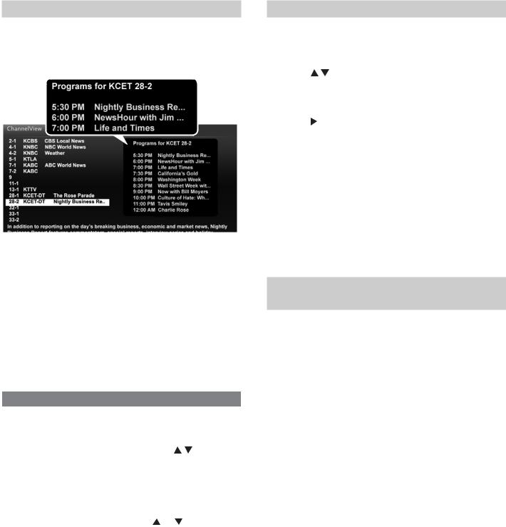
ChannelView displays program descriptions sent by broadcasters. This information may be unavailable in some areas.
ChannelView. Programs for the tuned channel are listed on right side of screen.
ChannelView™ shows memorized channels on the ANT input. It displays channel names and program information for digital channels as sent by broadcasters or your local cable service provider (information may be unavailable in some areas). No program information is displayed for analog channels.
Note: You must set the TV Clock (page 43) to receive ChannelView listings for the current channel.
Using ChannelView
Feature |
Instructions |
|
|
|
|
|
|
Display/hide ChannelView |
GUIDE |
|
|
listings from the ANT |
|
|
|
input. |
|
|
|
|
|
|
|
Receive updates for a |
1. |
Press |
to |
digital channel. |
|
highlight a channel |
|
|
|
number. |
|
|
2. |
Press the INFO key |
|
|
|
(the screen may |
|
|
|
briefly go blank). |
|
Scan channels one by one. |
Hold or |
|
|
|
|
||
Scan channels quickly. |
Hold PAGE UP/PAGE DN |
||
|
|
|
|
Jump to listings for a spe- |
1. |
Enter the channel |
|
cific channel. |
|
number. |
|
|
2. |
Press ENTER. |
|
|
|
|
|
See more of the program |
INFO |
|
|
description for the current |
|
|
|
channel (if available). |
|
|
|
|
|
|
|
Tune to the highlighted |
ENTER |
|
|
channel. |
|
|
|
|
|
|
|
In Canada call 1(800) 450-6487 for assistance.
Redirecting Audio Output
Selecting an Audio Output Device
1. |
Press MORE and then 9 (AUDIO). |
|
2. |
Press |
to show the Speakers option. The |
|
Speakers option will display only if there is a rec- |
|
|
ognized audio device on an audio output or HDMI |
|
|
input. |
|
3. |
Press |
to select either AV Receiver, Head- |
phones, or TV.
Note: The Headphones option displays only if you selected the name Headphones in the New Device Found screen.
Disconnecting an Analog A/V Receiver
When you disconnect an analog A/V receiver, change the Speakers setting to TV to hear sound from the TV speakers. Change the setting using the remote control’s MORE > 9 (AUDIO )key or the Adjust > Audio > Speakers menu.
Controlling A/V Receiver Sound Volume
Use one of the methods below to control sound volume from an A/V receiver.
With a Standard TV Setup
•Recommended Method: Program the TV’s remote control for your A/V receiver and enable the Audio Lock feature. See page 65.
•Program the TV’s remote control for your A/V receiver and set the TV remote control’s mode to AUDIO. Return the control mode to TV to control the TV.
•Use the remote control that came with the A/V receiver.
With HDMI Control (CEC-Enabled HDMI A/V Receiver)
The TV’s remote control may control some functions of the A/V receiver. See Appendix C, “HDMI Control of CEC Devices,” page 73.
With NetCommand IR Control
Model L75-A91. Set up NetCommand control of the A/V receiver’s volume functions in the Inputs > AVR menu. The TV’s remote will then control A/V receiver volume. See page 57.
3. Using TV Features |
27 |
Status Display
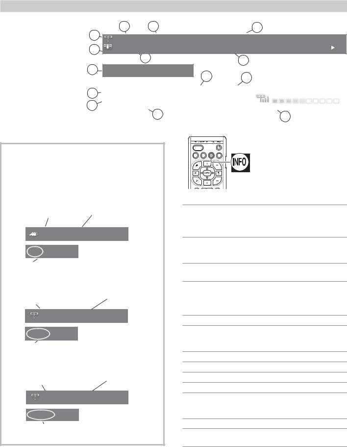
Press the INFO key to see the on-screen status display. The most common displays are shown here.
|
3 |
4 |
|
6 |
1 |
402-101 KABC |
Monday Night Football |
||
|
||||
2 |
TV-PG DLSV |
St. Louis vs. Tampa Bay, played in Tampa for |
||
|
|
|
|
|
|
5 |
|
|
7 |
|
|
|
|
|
8 Sleep 30 min |
|
12 |
13 |
|
|
|
|
||
Sample information |
|
|
|
|
|
9 |
Tuesday 9:10 PM |
Surround |
English |
||
from the on-screen |
|||||
|
HD 1080i Standard |
|
|
||
status display 10 |
|
|
|||
|
|
|
|||
11
About Channel Numbers
Channel Numbers for Over-the-Air Reception or Reception by Direct Cable
Note: All signals are automatically converted to 1080p for display.
Standard-Definition Analog Channels
Cable Reception |
|
Channel 3 |
Cable |
3 |
|
480i Stretch
Receiving Standard-Definition
Analog Signal (480i)
Standard-Definition Digital Channels
Over-the-Air |
|
Main Channel 7 |
Antenna Reception |
|
Sub-Channel 1 |
Ant |
7-1 KABC-SD |
|
SD 4:3 Stretch
Receiving Standard-Definition
Digital Signal (SD)
High-Definition Digital Channels
Over-the-Air |
|
Main Channel 7 |
Antenna Reception |
|
Sub-Channel 1 |
Ant |
7-1 KABC-HD |
|
HD 16:9 Stretch
Receiving High-Definition
Digital Signal (HD)
14
ACTIVITY
GUIDE MENU INFO BACK
1.Current Input
2.Audio Indicator.
 TV speakers
  External sound system
  Headphones
  Mute
Mute
3.Channel number (antenna source only)
Digital channel includes major and sub-channel numbers.
4.Digital channel name (if broadcast); antenna source only.
5.V-Chip rating
•Antenna source only for digital signal
•Antenna or VIDEO composite jack for analog signal
6.Program name (if broadcast); digital source only
7.Program description (if broadcast); digital source, antenna only. Press the INFO key additional times to see more of the description.
8.Sleep Timer remaining time
9.Day and time
10.Signal type being received
11.Screen format in use
12.Program Audio indicator (antenna source only)
•Digital source: Stereo, Surround
•Analog source: Stereo, Stereo SAP, SAP
13.Available language (digital source, antenna only)
14.Signal-strength indicator (digital source, antenna only)
In the U.S. call 1(877) 675-2224 for assistance.
28 |
3. Using TV Features |
TV Signals and Display Formats
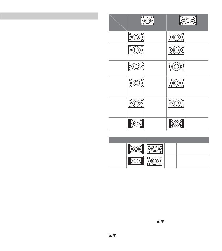
This is a 16:9 widescreen TV suitable for images available from HDTV and many DVDs. You can view older-style, squarish images (4:3 aspect ratio) using one of the display formats described on this page. Press the MORE key and then the
0 key (FORMAT) to cycle through available display formats. The TV remembers the format you last used for each input.
DVD Image Definitions
Image information may be stated on the DVD case. Some DVDs support both of the formats described below.
Anamorphic (or Enhanced for WideScreen TV)
Indicates DVDs recorded to show widescreen images properly on 16:9 TV sets using the TV’s Standard format mode (recommended).
Non-Anamorphic (or 4:3, 1.33:1, Letter Box, or Full Screen)
Indicates DVDs recorded for viewing on squarish TV screens. They may be full screen (4:3 or 1.33:1) which crops movies to fit the narrow TV, or letter box, which adds black top and bottom bars.
Signal Definitions
480i: Older type of interlaced signals from the ANT input, composite VIDEO, component Y Pb Pr, or HDMI jacks.
480p: Progressive-scan DVD signals on component Y Pb Pr or HDMI jacks.
720p and 1080i: High-definition signals received through component Y Pb Pr or HDMI jacks. These signals are always 16:9 (widescreen).
1080p: High-definition signals from a PC or Blu-ray player, HDMI inputs only.
SD 4:3: Standard-definition squarish-screen-format signals from digital channels on the ANT input.
SD 16:9: Standard-definition widescreen-format signals from digital channels on the ANT input.
HD 16:9: High-definition 16:9 widescreen signals from digital channels on the ANT input.
TV Display Format Definitions
Standard: The full-screen format used by HDTV signals. Use this format to display anamorphic DVDs with a 1.78:1 or 1.85:1 aspect ratio. Anamorphic DVDs with a 2.35:1 aspect ratio are displayed correctly but with top and bottom black bars. Squarish (4:3) images are stretched evenly from side to side. Available for all signals.
Expand: Enlarges the picture to fill the screen by cropping the top and bottom; useful for reducing the letter box top and bottom bars of non-anamorphic DVD images.
Zoom: Enlarges the picture to fill the screen by cropping the sides, top, and bottom to eliminate black bars.
•480i/480p and SD 4:3 signals: Eliminates top and bottom bars on anamorphic DVDs with a 2.35:1 aspect ratio.
•720p, 1080i, SD 16:9, and HD signals: Eliminates bars added to squarish 4:3 images.
In Canada call 1(800) 450-6487 for assistance.
Original
Signal
TV |
|
|
Display |
Non-anamorphic or SD 4:3 |
Anamorphic DVD |
Standard |
Distorted. |
Recommended |
|
Not recom- |
|
|
mended. |
|
Expand |
Recom- |
Distorted; not |
|
mended for |
recommended. |
|
letterbox. See |
See Note 1. |
|
Note 1. |
|
Zoom |
Distorted. |
Recommended |
|
Not recom- |
for anamorphic |
|
mended. See |
2.35:1 images. |
|
Note 1. |
See Note 1. |
Stretch |
Recom- |
Distorted; not |
|
mended for |
recommended. |
|
standard |
See Note 1. |
|
broadcasts. |
|
|
See Note 1. |
|
Stretch |
Recom- |
Distorted; not |
Plus |
mended for |
recommended. |
|
standard |
See Note 1. |
|
broadcasts. |
|
|
See Note 1. |
|
Narrow |
See Note 1 |
Distorted; not |
|
|
recommended. |
|
|
See Note 1. |
Note 1: Available for 480i, 480p, and digital SD 4:3 signals only.
Original Signal |
Display Formats |
|
SD 16:9 or |
Wide |
Recommended to re- |
HD Digital |
Expand move side bars. |
|
720p, 1080i, |
|
|
1080p Signal |
Zoom |
Recommended to re- |
|
||
|
|
move bars from the top, |
|
|
bottom, and sides. |
TV Display Formats. Press the MORE key and then repeatedly press the 0 key (FORMAT) to see the displays available for the current program. Press the INFO key to see the name of the display format in use.
Stretch: Stretches a squarish 4:3 image across the screen to display the entire image with less distortion than the Standard format.
Stretch Plus: Similar to Stretch, but minimizes distortion on the sides by expanding the picture to crop off portions of the top and bottom. Use to adjust the vertical position of the picture. L75-A91. Position adjustment may be unavailable if your NetCommand setup reassigned the
keys for the current device.
Narrow: Displays narrow 4:3 images in their original shape. Adds black side bars to fill the screen.
Wide Expand: Enlarges the picture, cropping the image on both sides. Removes or reduces black side bars added to narrow images converted to 16:9 signals for digital broadcast.
Note: All high-definition channels send widescreen (16:9) signals, but not all programming was created for the widescreen format. The broadcaster may stretch the image or add side bars to fill the widescreen area.
 Loading...