


 Loading...
MELSEC is registered trademark of Mitsubishi Electric Corporation.
Other company and product names that appear in this manual are trademarks or registered trademarks of the respective company.
Introduction
These specifications are the programming manual used when creating the sequence program for the EZMotion-NC E60/E68 with the onboard PLC development tool or PLC development software.
The PLC (Programmable Logic Controller) is largely divided into the basic commands, function commands and exclusive commands, and ample command types are available.
The commands can be used according to the purpose and application such as the PLC support function used when supporting the user PLCs.
Details described in this manual
 CAUTION
 For items described in "Restrictions" or "Usable State", the instruction manual issued by the machine maker takes precedence over this manual.
 Items not described in this manual must be interpreted as "not possible".
 This manual is written on the assumption that all option functions are added. Refer to the specifications issued by the machine maker before starting use.
 Refer to the Instruction Manual issued by each machine maker for details in each machine tool.
 Some screens and functions may differ or may not be usable depending on the NC version.
General precautions
(1)This Instruction Manual does not explain the operation procedures for programming the sequence program with onboard or personal computer. Refer to the related material listed below for details.
EZMotion-NC E60/E68 PLC Onboard Instruction Manual |
..... IB-1500179(ENG) |
|
EZMotion-NC E60/E68 |
PLC Interface Manual |
..... IB-1500176(ENG) |
EZMotion-NC E60/E68 |
PLC Development Software Manual |
..... IB-1500177(ENG) |
|
(MELSEC Tool Section) |
|

Precautions for Safety
Always read the specifications issued by the machine maker, this manual, related manuals and attached documents before installation, operation, programming, maintenance or inspection to ensure correct use.
Understand this numerical controller, safety items and cautions before using the unit.
This manual ranks the safety precautions into "DANGER", "WARNING" and "CAUTION".
|
|
|
When there is a great risk that the user could be subject to |
|
|
DANGER |
fatalities or serious injuries if handling is mistaken. |
|
|
|
When the user could be subject to fatalities or serious injuries |
|
|
|
|
|
|
WARNING |
|
|
|
if handling is mistaken. |
|
|
|
|
When the user could be subject to injuries or when physical |
|
|
|
|
|
|
|
|
|
|
CAUTION |
damage could occur if handling is mistaken. |
|
|
|
|
Note that even items ranked as "  CAUTION", may lead to major results depending
on the situation. In any case, important information that must always be observed is described.
 DANGER
Not applicable in this manual.
 WARNING
Not applicable in this manual.
 CAUTION
1. Items related to product and manual
For items described as "Restrictions" or "Usable State" in this manual, the instruction manual issued by the machine maker takes precedence over this manual.
An effort has been made to describe special handling of this machine, but items that are not described must be interpreted as "not possible".
This manual is written on the assumption that all option functions are added. Refer to the specifications issued by the machine maker before starting use.
Refer to the Instruction Manual issued by each machine maker for details on each machine tool.
Some screens and functions may differ or some functions may not be usable depending on the NC version.
2. Items related to start up and maintenance
Read this manual carefully and confirm the safety enough before executing the operation of the program change, forced output, RUN, STOP, etc. during operation. Operation mistakes may cause damage of the machine and accidents.
CONTENTS
1. |
System Configuration .................................................................................... |
1 |
||
|
1.1 |
System Configuration for PLC Development ............................................. |
1 |
|
|
1.2 |
User PLC (Ladder) Development Procedure.............................................. |
2 |
|
2. |
PLC Processing Program .............................................................................. |
3 |
||
|
2.1 |
PLC Processing Program Level and Operation ......................................... |
3 |
|
|
2.2 |
User Memory Area Configuration .............................................................. |
3 |
|
3. |
Input/Output Signals ...................................................................................... |
4 |
||
|
3.1 |
Input/Output Signal Types and Processing ............................................... |
4 |
|
|
3.2 |
Handling of Input Signals Designated for High-Speed Input ..................... |
5 |
|
|
3.3 |
High-Speed Input/output Designation Method ........................................... |
6 |
|
|
3.4 |
Limits for Using High Speed Processing Program ..................................... |
7 |
|
|
3.4.1 |
Separation of Main Processing and High Speed Processing Bit |
|
|
|
|
|
Operation Areas................................................................................... |
7 |
|
3.4.2 |
Separation of Remote I/O Output......................................................... |
8 |
|
4. |
Parameters ...................................................................................................... |
10 |
||
|
4.1 |
PLC Constants .......................................................................................... |
10 |
|
|
4.2 |
Bit Selection Parameters ........................................................................... |
11 |
|
5. |
Explanation of Devices .................................................................................. |
15 |
||
|
5.1 |
Devices and Device Numbers ................................................................... |
15 |
|
|
5.2 |
Device List ................................................................................................. |
15 |
|
|
5.3 |
Detailed Explanation of Devices ................................................................ |
16 |
|
|
5.3.1 |
Input/output X, Y ................................................................................. |
16 |
|
|
5.3.2 |
Internal Relays M and F, Latch Relay L .............................................. |
17 |
|
|
5.3.3 |
Special Relays SM .............................................................................. |
17 |
|
|
5.3.4 |
Timer T ................................................................................................ |
18 |
|
|
5.3.5 Counter C ............................................................................................ |
20 |
||
|
5.3.6 |
Data Register D ................................................................................... |
20 |
|
|
5.3.7 |
File Register R .................................................................................... |
21 |
|
|
5.3.8 |
Index Registers Z ................................................................................ |
22 |
|
|
5.3.9 |
Nesting N ............................................................................................ |
23 |
|
|
5.3.10 Pointer P ............................................................................................ |
24 |
||
|
5.3.11 Decimal Constant K ............................................................................ |
25 |
||
|
5.3.12 Hexadecimal Constant H .................................................................... |
25 |
||
6. |
Explanation of Commands ............................................................................ |
26 |
||
|
6.1 |
Command List ........................................................................................... |
26 |
|
|
6.1.1 Basic Commands ................................................................................ |
26 |
||
|
6.1.2 Function Commands ........................................................................... |
27 |
||
|
6.1.3 Exclusive commands ........................................................................... |
33 |
||
|
6.2 |
Command Formats ................................................................................... |
34 |
|
|
6.2.1 How to Read the Command Table ...................................................... |
34 |
||
|
6.2.2 |
No. of Steps ........................................................................................ |
35 |
|
|
6.2.3 END Command ................................................................................... |
36 |
||
|
6.2.4 Index Ornament .................................................................................. |
36 |
||
|
6.2.5 |
Digit Designation ................................................................................. |
37 |
|
7. Basic Commands |
|
||
|
(LD, LDI, AND, ANI, OR, ORI, ANB, ORB .....) ............................................... |
41 |
|
8. |
Function Commands |
|
|
|
(=, >, <, +, –, *, /, BCD, BIN, MOV .....) ............................................................ |
73 |
|
9. |
Exclusive Commands .................................................................................... |
190 |
|
|
9.1 ATC Exclusive Command ......................................................................... |
191 |
|
|
9.1.1 |
Outline of ATC Control ........................................................................ |
191 |
|
9.1.2 ATC Operation .................................................................................... |
191 |
|
|
9.1.3 |
Explanation of Terminology ................................................................. |
191 |
|
9.1.4 |
Relationship between Tool Registration Screen and Magazines ........ |
192 |
|
9.1.5 Use of ATC and ROT Commands ....................................................... |
193 |
|
|
9.1.6 Basic Format of ATC Exclusive Command ......................................... |
194 |
|
|
9.1.7 Command List ..................................................................................... |
195 |
|
|
9.1.8 |
Control Data Buffer Contents .............................................................. |
195 |
|
9.1.9 |
File Register (R Register) Assignment and Parameters ...................... |
196 |
|
9.1.10 Details of Each Command................................................................... |
198 |
|
|
9.1.11 Precautions for Using ATC Exclusive Instructions .............................. |
207 |
|
|
9.1.12 Examples of Tool Registration Screen ............................................... |
207 |
|
|
9.1.13 Display of Spindle Tool and Standby Tool .......................................... |
209 |
|
|
9.2 S.ROT Commands .................................................................................... |
210 |
|
|
9.2.1 Command List ...................................................................................... |
210 |
|
|
9.3 Tool Life Management Exclusive Command ............................................. |
216 |
|
|
9.3.1 Tool Life Management System ............................................................ |
216 |
|
|
9.3.2 Tool Command System ....................................................................... |
216 |
|
|
9.3.3 |
Spare Tool Selection System .............................................................. |
217 |
|
9.3.4 |
Interface .............................................................................................. |
217 |
|
9.3.5 User PLC Processing When the Tool Life Management Function |
|
|
|
|
Is Selected .......................................................................................... |
218 |
|
9.3.6 Examples of Tool Life Management Screen ........................................ |
226 |
|
|
9.4 DDB (Direct Data Bus) ... Asynchronous DDB .......................................... |
227 |
|
|
9.4.1 Basic Format of Command .................................................................. |
227 |
|
|
9.4.2 |
Basic Format of Control Data .............................................................. |
227 |
|
9.5 External Search ......................................................................................... |
230 |
|
|
9.5.1 |
Function .............................................................................................. |
230 |
|
9.5.2 |
Interface .............................................................................................. |
230 |
|
9.5.3 |
Search Start Instruction ....................................................................... |
232 |
|
9.5.4 |
Timing Charts and Error Causes ......................................................... |
232 |
|
9.5.5 Sequence Program Example .............................................................. |
234 |
|
|
9.6 Chopping..................................................................................................... |
235 |
|
|
9.6.1 |
Chopping operation start ...................................................................... |
236 |
|
9.6.2 |
Chopping operation stop ...................................................................... |
238 |
|
9.6.3 Chopping compensation....................................................................... |
239 |
|
|
9.6.4 |
Chopping interface ............................................................................... |
242 |
|
9.6.5 |
Parameters (DDB function instructions from PLC) ............................... |
243 |
|
9.6.6 Example of chopping control by program command ............................ |
249 |
|
10. PLC Help Function......................................................................................... |
252 |
||
10.1 |
Alarm Message Display............................................................................ |
253 |
|
10.1.1 |
Interface ............................................................................................. |
253 |
|
10.1.2 |
Screen Display ................................................................................... |
255 |
|
10.1.3 Message Creation .............................................................................. |
256 |
||
10.1.4 |
Parameters......................................................................................... |
259 |
|
10.2 |
Operator Message Display....................................................................... |
261 |
|
10.2.1 |
Interface ............................................................................................. |
261 |
|
10.2.2 |
Operator Message Preparation .......................................................... |
262 |
|
10.2.3 |
Operator Message Display Validity Parameter................................... |
262 |
|
10.3 |
PLC Switches........................................................................................... |
263 |
|
10.3.1 |
Explanation of Screen ........................................................................ |
263 |
|
10.3.2 |
Explanation of Operation.................................................................... |
264 |
|
10.3.3 |
Signal Processing............................................................................... |
265 |
|
10.3.4 |
Switch Name Preparation................................................................... |
269 |
|
10.4 |
Key Operation by User PLC ..................................................................... |
270 |
|
10.4.1 Key Data Flow.................................................................................... |
270 |
||
10.4.2 Key Operations That Can Be Performed............................................ |
270 |
||
10.4.3 |
Key Data Processing Timing .............................................................. |
271 |
|
10.4.4 |
Layout of Keys on Setting and Display Unit ....................................... |
272 |
|
10.4.5 |
List of Key Codes ............................................................................... |
273 |
|
10.5 |
Load Meter Display .................................................................................. |
274 |
|
10.5.1 |
Interface ............................................................................................. |
274 |
|
10.6 |
External Machine Coordinate System Compensation .............................. |
276 |
|
10.7 |
User PLC Version Display........................................................................ |
277 |
|
10.7.1 |
Interface ............................................................................................. |
277 |
|
11. PLC Axis Control ........................................................................................... |
279 |
|||
11.1 |
Outline...................................................................................................... |
|
279 |
|
11.2 |
Specifications ........................................................................................... |
279 |
||
11.2.1 |
Basic Specifications ........................................................................... |
279 |
||
11.2.2 |
Other Restrictions .............................................................................. |
280 |
||
11.3 |
PLC Interface ........................................................................................... |
281 |
||
11.3.1 S.DDBS Function Command.............................................................. |
281 |
|||
11.3.2 |
Control Information Data .................................................................... |
282 |
||
11.3.3 |
Control Information Data Details ........................................................ |
283 |
||
|
11.3.3.1 Commands ................................................................................ |
283 |
||
|
11.3.3.2 |
Status ........................................................................................ |
284 |
|
|
11.3.3.3 Alarm No.................................................................................... |
291 |
||
|
11.3.3.4 |
Control Signals (PLC axis control information data) .................. |
292 |
|
|
11.3.3.5 |
Axis Designation........................................................................ |
294 |
|
|
11.3.3.6 |
Operation Mode......................................................................... |
294 |
|
|
11.3.3.7 |
Feedrate .................................................................................... |
295 |
|
|
11.3.3.8 Movement Data ......................................................................... |
295 |
||
|
11.3.3.9 |
Machine Position ....................................................................... |
296 |
|
|
11.3.3.10 Remaining Distance.................................................................. |
296 |
||
11.3.4 |
Reference Point Return Near Point Detection.................................... |
297 |
||
11.3.5 |
Handle Feed Axis Selection ............................................................... |
298 |
||
12. Appendix ....................................................................................................... |
299 |
12.1 Example of Faulty Circuit ......................................................................... |
299 |
1. System Configuration
1. System Configuration
1.1 System Configuration for PLC Development
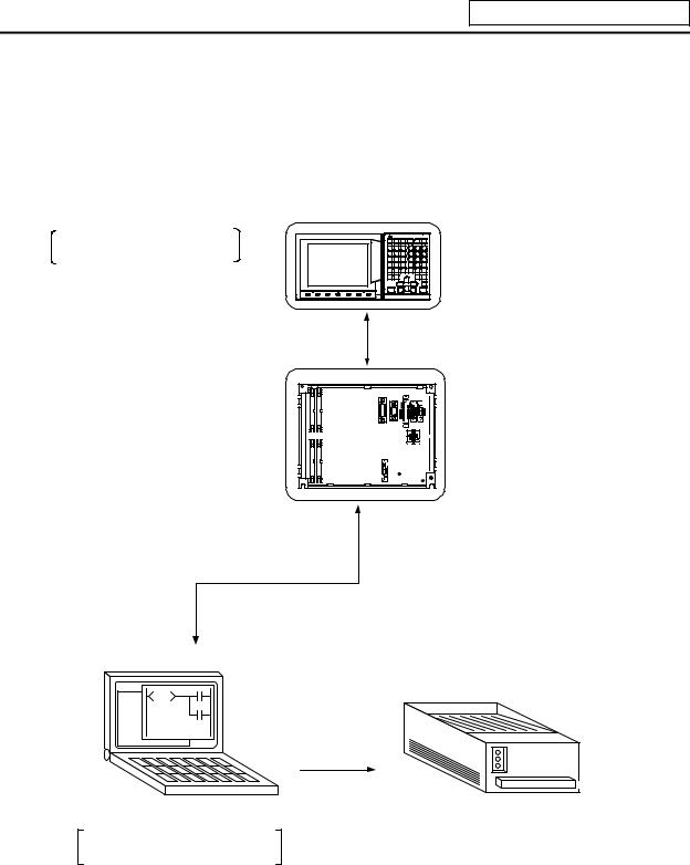
The system configuration for PLC development is shown below.
Ladder editing, ladder monitor and PLC RUN/STOP, etc.
A new development is possible with the personal computer.
and |
Unit |
Settinging and DisplaDisplayUnit |
|
The ladder is developed using the setting and display unit. (Onboard development)
BaseI/OI/OUnitUnit
To connector RS-232C
RS-232C
Up/downloading is carried out with the personal computer's development tool.
Personal computer
General printer
Used for ladder development, creating message, ladder monitor and saving data.
(Note) Refer to the "PLC Onboard Instruction Manual" (IB-1500179) for edition using the setting and display unit (onboard edition), and the "PLC Development Software Manual (MELSEC Tool Section)" (IB-1500177) for development using the personal computer.
- 1 -
1. System Configuration
1.2 User PLC (Ladder) Development Procedure
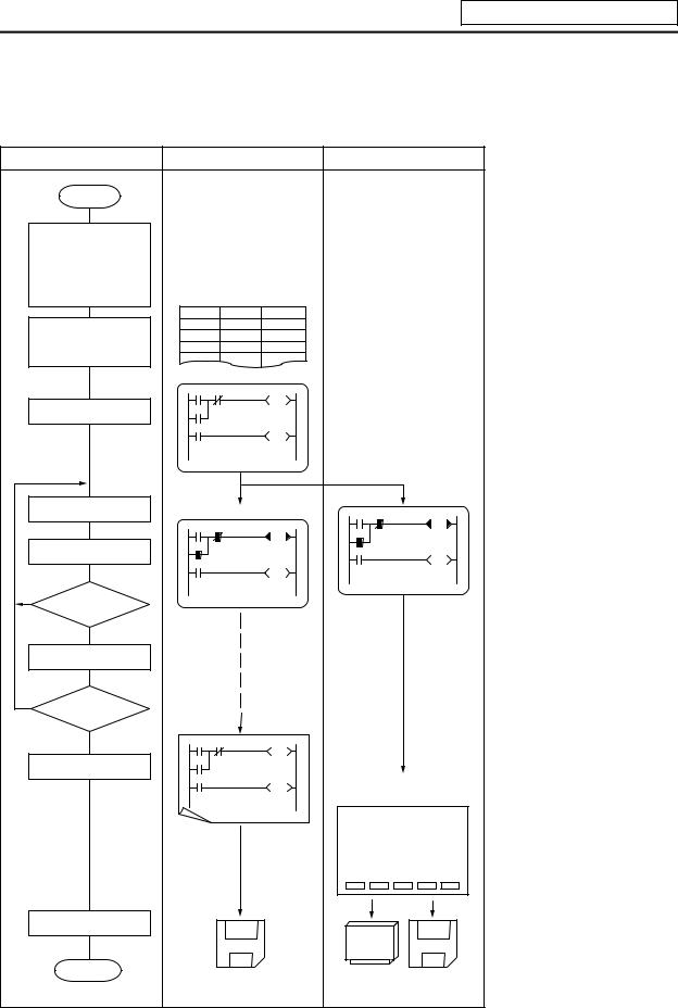
The procedure for creating the user PLC, used to control the control target (machine) built into the control unit, is shown below.
|
Procedure |
Personal |
Computer |
CNC Unit |
|
|||
|
Start |
|
|
|
|
|
|
|
|
Determination of |
|
|
|
|
|
|
|
|
machine |
|
|
|
|
|
|
|
|
Determination of |
|
|
|
|
|
|
|
|
CNC and PLC |
|
|
|
|
|
|
|
|
specifications |
Commercially available |
|
|
|
|||
|
Determination of the |
|
|
|
||||
|
numbers of I/O points |
spreadsheet tool |
|
|
|
|||
|
Assignment of I/O |
Device |
Name |
Comment |
|
|
|
|
|
X0 |
X-OT |
|
X-axis OT |
|
|
|
|
|
signals |
X1 |
Y-OT |
|
Y-axis OT |
|
|
|
|
Assignment of |
X2 |
Z-OT |
|
Z-axis OT |
|
|
|
|
internal relays |
GX Developer |
|
|
|
|
||
|
|
|
|
|
|
|||
|
Programming |
|
|
|
|
|
|
|
|
Debugging operation |
GX Developer |
|
Onboard |
|
|
||
|
|
|
|
|
||||
|
|
|
|
|
|
|
|
|
|
Program correction |
|
|
|
|
|
|
|
|
Is debugging |
|
|
|
|
|
|
|
NO |
complete? |
|
|
|
|
|
|
|
|
YES |
|
|
|
|
|
|
|
|
Test operation by |
|
|
|
|
|
|
|
|
CNC unit |
|
|
|
|
|
|
|
|
Is test operation |
|
|
|
|
|
|
|
NO |
OK? |
GX Developer |
|
|
|
|
|
|
|
YES |
|
|
|
|
|
|
|
|
Printout |
|
|
|
|
|
|
|
|
|
|
|
|
|
BACKUP screen |
|
|
|
|
|
|
|
|
DATA IN/OUT screen |
||
|
|
|
|
|
|
[BACKUP] |
PARAM 3.2/2 |
|
|
|
|
|
|
|
|
|
|
|
|
|
|
|
|
#1 BACKUP |
####### |
|
|
|
|
|
|
|
#2 RESTORE |
######### |
|
|
|
|
|
|
|
#( ) ( |
) |
|
|
Data save |
|
|
|
|
|
|
|
|
Com pletion |
Program data |
Memory cassette Binary |
|
||||
|
|
data |
||||||
|
|
|
|
|
|
(F-ROM) |
|
|
|
|
|
|
|
|
- 2 - |
|
|
The data created with the commercially available spreadsheet tool can be used as ladder comment data.
Use GX Developer for programming.
After completion, download the data through RS-232C.
Perform monitoring/correction with GX Developer's online function or onboard function.
Printout to a commercial printer connected with the personal computer from GX Developer.
Excute the ROM backup operation on the BACKUP screen.
Excute the binary data output on the DATA IN/OUT screen.
Program data:
Saved using GX Developer
Binary data:
Saved using DATA IN/OUT screen
2. PLC Processing Program
2. PLC Processing Program
2.1 PLC Processing Program Level and Operation
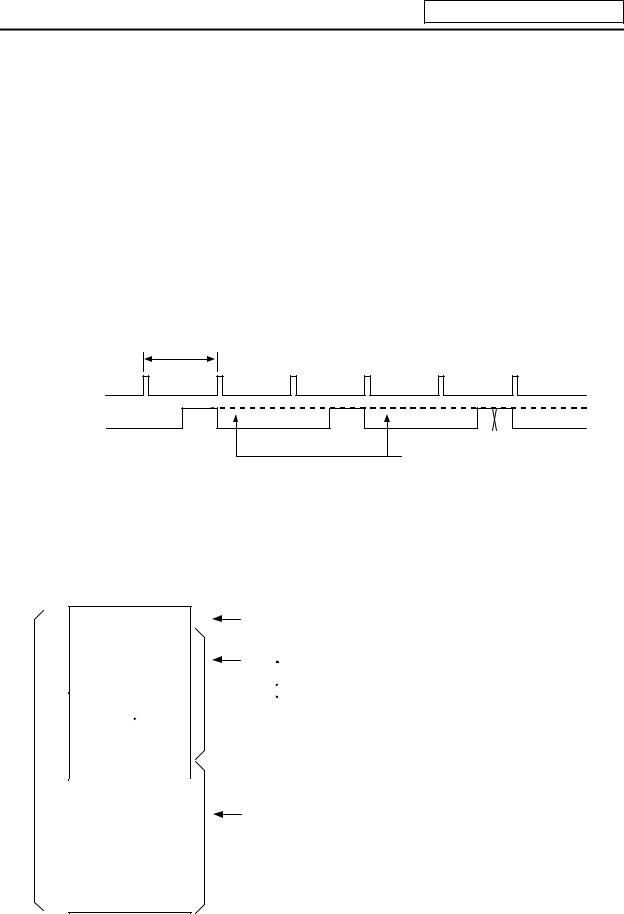
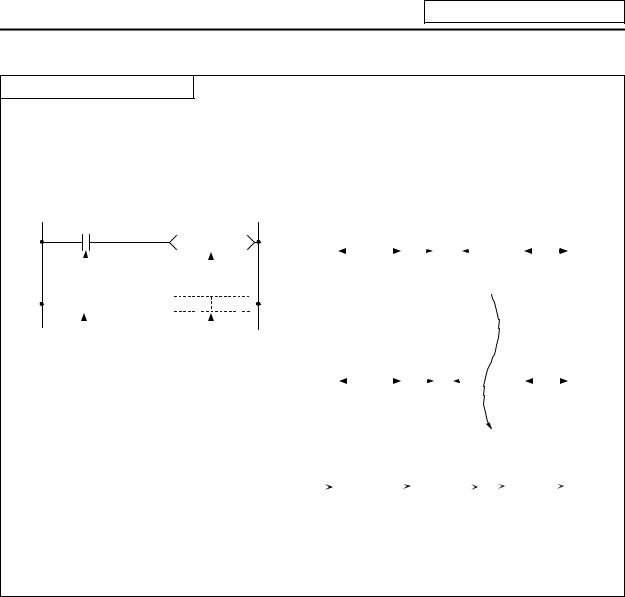
Table 2.1-1 explains the contents of users PLC processing level and Fig. 2.1-1 shows the timing chart.
|
Table 2.1-1 PLC processing level |
|
|
Program name |
Description (frequency, level, etc.) |
|
|
High-speed processing |
This program starts periodically with a time interval of 7.1ms. |
program |
This program has the highest level as a program that starts periodically. |
|
It is used in signal processing where high-speed processing is required. |
|
Processing time of this program shall not exceed 0.5ms. |
|
Application example: |
|
Position count control of turret and ATC magazine |
Main processing |
This program runs constantly. When one ladder has been executed from |
program (ladder) |
the head to END, the cycle starts again at the head. |
7.1ms
High-speed processing
Main processing
(Note 1)
This section is used by the controller.
(Note 1) The section from the END command to the next scan is done immediately as shown with the X section. Note that the min. scan time will be 14.2ms.
Fig. 2.1-1 PLC processing program operation timing chart
2.2 User Memory Area Configuration
The user memory area approximate configuration and size are shown below.
|
|
|
|
Control information |
|
|
|
|
|
|
|
|
|
|
|
Message data |
|
|
|
|
|
|
|
|
|
|
Contact coil |
|
|
User PLC |
|
|
|||
code area |
|
|
comment data |
|
|
|
|
|
|
|
|
|
|
|
|
|
|
P251 |
|
|
|
||
|
High-speed processing |
||||
P252 |
|
|
|||
Main Processing
Max. 256Kbyte from control information to messages.
Internal information table of User PLC (The table is automatically generated.)
Data excepting the ladder program Alarm messages
 Operator messages PLC switches
Load meter
 Contact
  coil comment data, etc.
(Each of them can be stored in two languages.)
Total 127Kbyte
Program with the ladder language
Programs excepting the main processing are not necessary.
The program order of initial, high-speed and main processing is random.
Total 4000 steps
- 3 -
3. Input/Output Signals
3. Input/Output Signals
3.1 Input/Output Signal Types and Processing
The input/output signals handled in user PLC are as follows:
(1)Input/output from/to controller
(2)Input/output from/to operation board (Note 1)
(3)Input/output from/to machine
The user PLC does not directly input or output these signals from or to hardware or controller; it inputs or outputs the signals from or to input/output image memory. For the reading and writing with the hardware or controller, the controller will perform the input/output according to the level of the main process or high-speed process.
Controller |
|
|
|
|
|
|
|
|
|
|
|
|
|
|
|
|
|
|
|
|
|
|
|
|
|
Input/output image |
|
|
|
|
|
|
|
|
|
|
|
|
|
Operation |
|
|
|
Controller |
|
|
|
User PLC |
|
|
|
|
|
memory |
|
|
|||
board |
|
|
|
|
|
|
|||
|
|
|
|
|
(device X, Y) |
|
|
|
|
|
|
|
|
|
|
|
|
|
|
|
|
|
|
|
|
|
|
|
|
Machine |
|
|
|
|
|
|
|
|
|
|
|
|
|
|
|
|
|
|
|
|
|
|
|
|
|
|
|
|
|
|
|
|
|
|
|
|
|
|
|
(Note 1) The operation board here refers to when the remote I/O unit is installed on the communication terminal.
Fig. 3.1-1 Concept of input/output processing
High-speed processing input/output
The controller reads the high-speed input designation input, and
sets in the im age m em ory.
P251
User PLC high -speed processing
The controller outputs the high-speed output designation output from the im age mem ory to the m achine.
Main processing input/output
The controller reads the
input other than the high-speed input designation,
and sets in the im age memory.
P252
User PLC m ain processing
The controller outputs the output other than the high-speed output designation from the
image m em ory to the m achine.
Fig. 3.1-2 Input/output processing conforming to program level
- 4 -
3. Input/Output Signals
Table 3.1-1 lists whether or not high-speed input/output, interrupt input and initial processing can be performed.
Table 3.1-1 Whether or not high-speed input/output, interrupt input and initial can be performed
|
|
High-speed input |
High-speed output |
|
|
specification |
specification |
|
|
|
|
Input signal from control unit |
x |
x |
|
|
|
|
|
Output signal to control unit |
x |
x |
|
|
|
|
|
Input signal from machine |
(2-byte units) |
x |
|
|
|
|
|
Output signal to machine |
x |
(2-byte units) |
|
|
|
|
|
Input signal from operation board |
x |
x |
|
Output signal to operation board |
x |
x |
|
: Possible |
x : Not possible |
|
|
The operation board in Table 3.1-1 is applied when control is performed by operation board input/output card that can be added as NC option.
3.2 Handling of Input Signals Designated for High-Speed Input
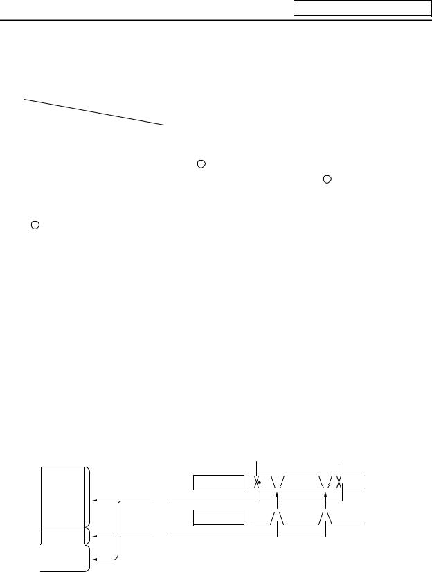
The input/output signals used in user PLC are input/output for each program level as shown in Fig. 3.1-2.
In high-speed processing, input/output signal for which high-speed input or output designation (parameter) is made is input or output each time the high-speed processing program runs. In main processing, signals other than interrupt input signals or high-speed input/output designation are input/output.
When high-speed input designation signal is used in main processing, the input signal may change within one scan because high-speed processing whose level is higher than main processing interrupts. Input signal which must not change within one scan should be saved in temporary memory (M), etc., at the head of main processing and the temporary memory should be used in the main program, for example.
Input image memory
 PLC one scan
Main |
A |
B |
A |
processing |
|
|
|
(1) |
|
|
|
High-speed processing
(2)
(1) Set at the head of main processing.
(2) Set at the head of high-speed processing.
The hatched area is high-speed input designation part. Whenever the high-speed processing program runs, data is reset in the hatched area. Thus, the signal in the hatched area may change in main processing (A) and (B) because the high-speed process interrupts between (A) and (B) and re-reads the input signal in the hatched area.
- 5 -
3. Input/Output Signals
3.3 High-Speed Input/output Designation Method
High-speed input/output is designated by setting the corresponding bit of the bit selection parameter as shown below.
(1) High-speed input designation
(2) High-speed output designation
·As listed above, one bit corresponds to two bytes (16 points).
·Input or output in which 1 is set in the table is not performed at the main processing program level.
·Although the number of bits set to 1 is not limited, set only necessary ones from viewpoint of overhead.
·High-speed input/output designation corresponds to the bit selection parameter and can be set in the parameter. However, it is recommended to set in a sequence program to prevent a parameter setting error, etc.
Example: —[MOV H3 R2928]— ..... To designate X00~X0F, X10~X1F (bit 0 and 1 for H3)
- 6 -
3. Input/Output Signals
3.4 Limits for Using High Speed Processing Program
3.4.1Separation of Main Processing and High Speed Processing Bit Operation Areas
(1)Bit operation area
When using high speed processing, the bit operation range such as the temporary memory is separated from the main process.
(Method 1) When using the same M or G code, the bit operation area for high speed processing and the bit operation area for main processing are separated by 64 points or more and used.
For example, the following is used |
|
M0 to M4735 for main processing |
Separate by 64 points or more |
M4800 to M5120 for high speed processing |
(M4736 to M4799 are not used) |
(Method 2) M is used for the main processing temporary memory and G is used for the high speed processing temporary memory.
(Note 1) The output devices handled with high speed processing must be limited to M or Y, D and R.
(Note 2) These limits apply not only to the OUT command, but also to the PLF, PLS, SET, RST and MOV command, etc., outputs. The devices apply to all devices including M, F, L, SM, T and C.
Interlock
Output to NC
Separated by 64 points or mpre during the MOV command.
- 7 -
3. Input/Output Signals
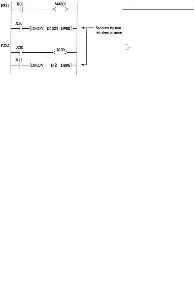
(2)Data area
Even with commands that handle data (numerical values) during the MOV command, etc., the bit area must be separated by 64 points or more and the data register (D) and file register (R) separated by four registers or more.
Example) Use D0 to D896 for main processing |
Separate by four registers or more |
|
Use D900 to D1023 for high speed processing |
||
|
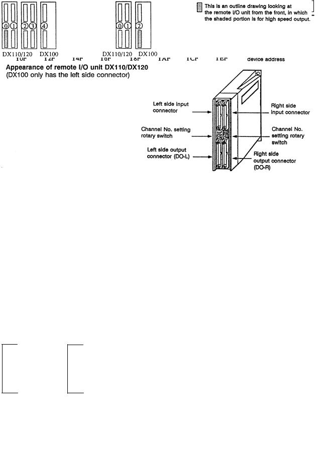
3.4.2 Separation of Remote I/O Output
When handling high speed output during the high speed process, the main processing output and high speed processing output cannot be used together in the same remote I/O unit (32 points in channel No. setting rotary switch). A separate 32 points for high speed processing output or a 16-point remote I/O unit will be required.
MOV commands, etc., that extend over differing remote I/O units must not be enforced during either main processing or high speed processing. If these must be enforced, the channel No. setting rotary switch for the output unit used in the main processing and the output unit used for the high speed processing must be set 1 or more apart.
M10
- 8 -
3. Input/Output Signals
(Usage example 1) Avoid interference with the main process by assigning 7 (last channel) for the channel No. rotary switch for high speed processing output.
For example, use YE0 to YFF (for 32-point DO-L) or YE0 to YEF (for 16-point DO-R) as the high speed processing output.
(Refer to <Usage examples 1-1, 1-2 and 1-3> below.)
(Usage example 2) Assign Y0 to Y1F (32-point) for high speed processing, and use Y20 and following for the main process.
(Refer to <Usage example 2> below.)
(Usage example 3) Assign the device after the device used for main processing for the high speed process.
For example, if the devices up to Y2D are used for the main process, use Y40 to Y5F (channel No. setting rotary switch No.: 2) for the high speed process. (Refer to <Usage example 3> below.)
Relation of channel No. setting switch and device No.
<Usage example 1-1> |
<Usage example 1-2> |
(Devices are YE0 and following)
Usage examples 1-2 show the assignment for the 16-point unit as the No. of high speed output points is relatively low.
|
|
|
|
|
|
|
|
|
|
|
|
|
|
|
DX35*/45* DX100 |
|
DX35*/45* DX110/120 |
|
|||||||||
|
|
|
|
|
|
|
|
|
|
|
|
|
|
<Usage example 2> |
|
|
<Usage example 3> |
||||||||||
|
|
|
|
|
|
|
|
|
|
|
|
|
|
|
|
|
|
|
|
|
|
|
|
|
|
|
|
|
|
|
|
|
|
|
|
|
|
|
|
|
|
|
|
|
|
|
|
|
|
|
|
|
|
|
|
|
|
|
|
|
|
|
|
|
|
|
|
|
|
DX35*/45* DX100 DX100 |
|
DX35*/45* DX100 |
/120 |
|
|
|
|
|
- 9 -
4. Parameters
4. Parameters
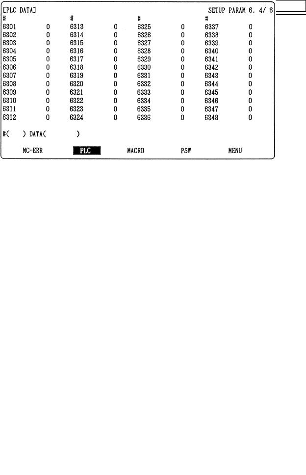
4.1 PLC Constants
The parameters that can be used in user PLC include PLC constants set in the data type.
Set up data is stored in a file register and is backed up. In contrast, if data is stored in the file register corresponding to PLC constant by using sequence program MOV instruction, etc., it is backed up. However, display remains unchanged. Display another screen once and then select the screen again.
48 PLC constants are set (the setting range is ±8 digits). (Signed 4-byte binary data)
The correspondence between the PLC constants and file registers is listed below. The setting and display screens are also shown.
# |
Corresponding file registers |
|
# |
Corresponding file registers |
|
# |
Corresponding file registers |
|||
High order |
Low order |
|
High order |
Low order |
|
High order |
Low order |
|||
|
|
|
|
|
||||||
6301 |
R2801 |
R2800 |
|
6321 |
R2841 |
R2840 |
|
6341 |
R2881 |
R2880 |
6302 |
R2803 |
R2802 |
|
6322 |
R2843 |
R2842 |
|
6342 |
R2883 |
R2882 |
6303 |
R2805 |
R2804 |
|
6323 |
R2845 |
R2844 |
|
6343 |
R2885 |
R2884 |
6304 |
R2807 |
R2806 |
|
6324 |
R2847 |
R2846 |
|
6344 |
R2887 |
R2886 |
6305 |
R2809 |
R2808 |
|
6325 |
R2849 |
R2848 |
|
6345 |
R2889 |
R2888 |
6306 |
R2811 |
R2810 |
|
6326 |
R2851 |
R2850 |
|
6346 |
R2891 |
R2890 |
6307 |
R2813 |
R2812 |
|
6327 |
R2853 |
R2852 |
|
6347 |
R2893 |
R2892 |
6308 |
R2815 |
R1814 |
|
6328 |
R2855 |
R2854 |
|
6348 |
R2895 |
R2894 |
6309 |
R2817 |
R2816 |
|
6329 |
R2857 |
R2856 |
|
|
|
|
6310 |
R2819 |
R2818 |
|
6330 |
R2859 |
R2858 |
|
|
|
|
6311 |
R2821 |
R2820 |
|
6331 |
R2861 |
R2860 |
|
|
|
|
6312 |
R2823 |
R2822 |
|
6322 |
R2863 |
R2862 |
|
|
|
|
6313 |
R2825 |
R2824 |
|
6333 |
R2865 |
R2864 |
|
|
|
|
6314 |
R2827 |
R2826 |
|
6334 |
R2867 |
R2866 |
|
|
|
|
6315 |
R2829 |
R2828 |
|
6335 |
R2869 |
R2868 |
|
|
|
|
6316 |
R2831 |
R2830 |
|
6336 |
R2871 |
R2870 |
|
|
|
|
6317 |
R2833 |
R2832 |
|
6337 |
R2873 |
R2872 |
|
|
|
|
6318 |
R2835 |
R2834 |
|
6338 |
R2875 |
R2874 |
|
|
|
|
6319 |
R2837 |
R2836 |
|
6339 |
R2877 |
R2876 |
|
|
|
|
6320 |
R2839 |
R2838 |
|
6340 |
R2879 |
R2878 |
|
|
|
|
PLC constant screen
- 10 -

4. Parameters
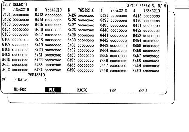
4.2 Bit Selection Parameters
The parameters that can be used in user PLC include bit selection parameters set in the bit type. Set up data is stored in a file register and is backed up.
For use in bit operation in a sequence program, the file register contents are transferred to temporary memory (M) using the MOV command. In contrast, if data is stored in the file register corresponding to bit selection by using the MOV command etc., it is backed up. However, display remains unchanged. Once display another screen and again select screen.
The corresponding between the bit selection parameters and file registers is listed below. The setting and display screens are also shown.
# |
Corresponding |
|
# |
Corresponding |
|
# |
Corresponding |
|
# |
Corresponding |
file register |
|
file register |
|
file register |
|
file register |
||||
|
|
|
|
|
|
|
||||
6401 |
R2900-LOW |
|
6433 |
R2916-LOW |
|
6449 |
R2924-LOW |
|
6481 |
R2940-LOW |
6402 |
R2900-HIGH |
|
6434 |
R2916-HIGH |
|
6450 |
R2924-HIGH |
|
6482 |
R2940-HIGH |
6403 |
R2901-L |
|
6435 |
R2917-L |
|
6451 |
R2925-L |
|
6483 |
R2941-L |
6404 |
R2901-H |
|
6436 |
R2917-H |
|
6452 |
R2925-H |
|
6484 |
R2941-H |
6405 |
R2902-L |
|
6437 |
R2918-L |
|
6453 |
R2926-L |
|
6485 |
R2942-L |
6406 |
R2902-H |
|
6438 |
R2918-H |
|
6454 |
R2926-H |
|
6486 |
R2942-H |
6407 |
R2903-L |
|
6439 |
R2919-L |
|
6455 |
R2927-L |
|
6487 |
R2943-L |
6408 |
R2903-H |
|
6440 |
R2919-H |
|
6456 |
R2927-H |
|
6488 |
R2943-H |
6409 |
R2904-L |
|
6441 |
R2920-L |
|
6457 |
R2928-L |
|
6489 |
R2944-L |
6410 |
R2904-H |
|
6442 |
R2920-H |
|
6458 |
R2928-H |
|
6490 |
R2944-H |
6411 |
R2905-L |
|
6443 |
R2921-L |
|
6459 |
R2929-L |
|
6491 |
R2945-L |
6412 |
R2905-H |
|
6444 |
R2921-H |
|
6460 |
R2929-H |
|
6492 |
R2945-H |
6413 |
R2906-L |
|
6445 |
R2922-L |
|
6461 |
R2930-L |
|
6493 |
R2946-L |
6414 |
R2906-H |
|
6446 |
R2922-H |
|
6462 |
R2930-H |
|
6494 |
R2946-H |
6415 |
R2907-L |
|
6447 |
R2923-L |
|
6463 |
R2931-L |
|
6495 |
R2947-L |
6416 |
R2907-H |
|
6448 |
R2923-H |
|
6464 |
R2931-H |
|
6496 |
R2947-H |
6417 |
R2908-L |
|
Use bit selection |
|
6465 |
R2932-L |
|
Bit selection parameter |
||
6418 |
R2908-H |
|
parameters |
|
6466 |
R2932-H |
|
#6449~#6496 are PLC |
||
|
|
|
#6401~#6448 freely. |
|
|
|
|
operation selection |
||
6419 |
R2909-L |
|
|
6467 |
R2933-L |
|
||||
|
|
|
|
|
parameters used by the |
|||||
6420 |
R2909-H |
|
|
|
|
6468 |
R2933-H |
|
||
|
|
|
|
|
machine manufacturer |
|||||
6421 |
R2910-L |
|
|
|
|
6469 |
R2934-L |
|
and MITSUBISHI. The |
|
6422 |
R2910-H |
|
|
|
|
6470 |
R2934-H |
|
contents are fixed. |
|
6423 |
R2911-L |
|
|
|
|
6471 |
R2935-L |
|
|
|
6424 |
R2911-H |
|
|
|
|
6472 |
R2935-H |
|
|
|
6425 |
R2912-L |
|
|
|
|
6473 |
R2936-L |
|
|
|
6426 |
R2912-H |
|
|
|
|
6474 |
R2936-H |
|
|
|
6427 |
R2913-L |
|
|
|
|
6475 |
R2937-L |
|
|
|
6428 |
R2913-H |
|
|
|
|
6476 |
R2937-H |
|
|
|
6429 |
R2914-L |
|
|
|
|
6477 |
R2938-L |
|
|
|
6430 |
R2914-H |
|
|
|
|
6478 |
R2938-H |
|
|
|
6431 |
R2915-L |
|
|
|
|
6479 |
R2939-L |
|
|
|
6432 |
R2915-H |
|
|
|
|
6480 |
R2939-H |
|
|
|
- 11 -
4. Parameters
Bit selection screen
- 12 -

4. Parameters
Contents of bit selection parameters #6449~#6496
|
Symbol |
|
7 |
6 |
5 |
|
4 |
3 |
2 |
|
1 |
0 |
|
name |
|
|
|
||||||||
|
|
|
|
|
|
|
|
|
|
|
|
|
|
#6449 |
|
NC card |
Setting |
|
|
Counter C |
Integrating |
PLC counter |
PLC timer |
||
|
|
|
Controller |
display unit |
|
|
||||||
0 |
R2924 |
L |
thermal |
thermal |
- |
|
retention |
timer T |
program on |
program on |
||
|
|
|
alarm on |
alarm on |
|
|
|
|
retention |
|
|
|
|
|
|
|
|
|
|
|
1 |
0 |
|
||
|
#6450 |
|
|
External |
Alarm/ |
Full screen |
|
Operator |
|
|||
|
R2924 |
H |
|
alarm |
- |
R |
F |
Alarm |
||||
1 |
|
operator |
display of |
message |
||||||||
|
message |
system system message on |
||||||||||
|
|
|
|
change |
message |
|
on |
|||||
|
|
|
|
display |
|
|
|
|
||||
|
|
|
|
|
|
|
|
|
|
|
|
|
|
#6451 |
|
|
|
GX-Developer |
PLC |
|
|
Onboard |
|
|
|
2 |
R2925 |
L |
- |
- |
communi- |
development |
|
editing not |
|
- |
Onboard on |
|
environment |
|
possible |
|
|||||||||
|
|
|
|
|
cation on |
|
|
|
|
|||
|
|
|
|
|
selection |
|
|
|
|
|
||
|
|
|
|
|
|
|
|
|
|
|
||
|
#6452 |
|
|
|
GOT |
|
Counter |
Integrating |
|
|
|
|
|
R2925 |
H |
|
|
communi- |
|
timer |
|
|
|
||
3 |
- |
|
|
(fixed) |
|
|
- |
|||||
|
cation |
|
(fixed) |
|
|
|||||||
|
|
|
|
|
|
retention |
|
|
|
|||
|
|
|
|
|
connection |
|
retention |
|
|
|
||
|
|
|
|
|
|
|
|
|
|
|
||
|
#6453 |
|
|
|
|
|
|
|
|
|
Message |
|
|
R2926 |
L |
|
|
|
|
|
|
|
|
||
4 |
- |
- |
- |
|
- |
- |
|
|
language |
|||
|
|
|
|
|
|
|
|
|
|
|
change code |
|
|
#6454 |
|
|
|
|
|
|
|
|
Equivalent of |
|
|
5 |
R2926 |
H |
|
|
|
|
|
|
|
|
||
|
|
|
|
|
|
|
remote I/O 2ch |
|
||||
|
|
|
|
|
|
|
|
|
|
|
||
|
#6455 |
|
|
|
|
|
|
|
|
|
|
|
6 |
R2927 |
L |
- |
- |
- |
|
- |
- |
- |
|
- |
- |
|
|
|
|
|||||||||
|
#6456 |
|
|
|
|
|
|
|
|
|
|
|
7 |
R2927 |
H |
- |
- |
- |
|
- |
- |
- |
|
- |
- |
|
#6457 |
|
|
|
|
|
|
|
|
|
|
|
8 |
R2928 |
L |
|
High-speed input specification 1 |
|
|
|
|
|
|
||
|
#6458 |
|
|
|
|
|
|
|
|
|
|
|
9 |
R2928 |
H |
|
High-speed input specification 2 |
|
|
|
|
|
|
||
|
#6459 |
|
|
|
|
|
|
|
|
|
|
|
A |
R2929 |
L |
|
High-speed input specification 3 |
(Spare) |
|
|
|
|
|
||
|
#6460 |
|
|
|
|
|
|
|
|
|
|
|
B |
R2929 |
H |
|
High-speed input specification 4 |
(Spare) |
|
|
|
|
|
||
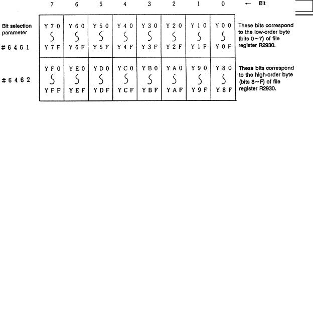
|
#6461 |
|
|
|
|
|
|
|
|
|
|
|
C |
R2930 |
L |
|
High-speed output specification 1 |
|
|
|
|
|
|
||
|
#6462 |
|
|
|
|
|
|
|
|
|
|
|
D |
R2930 |
H |
|
High-speed output specification 2 |
|
|
|
|
|
|
||
|
#6463 |
|
|
|
|
|
|
|
|
|
|
|
E |
R2931 |
L |
|
High-speed output specification 3 |
(Spare) |
|
|
|
|
|
||
|
#6464 |
|
|
|
|
|
|
|
|
|
|
|
F |
R2931 |
H |
|
High-speed output specification 4 |
(Spare) |
|
|
|
|
|
||
|
|
|
|
|
|
|
- 13 - |
|
|
|
|
|
4. Parameters
|
Symbol |
7 |
6 |
5 |
|
4 |
|
3 |
2 |
1 |
0 |
||
|
name |
|
|
|
|||||||||
|
|
|
|
|
|
|
|
|
|
|
|
|
|
0 |
#6465 |
|
- |
- |
- |
|
- |
|
- |
- |
- |
- |
|
R2932 |
L |
|
|
||||||||||
|
|
|
|
|
|
|
|
|
|
|
|
||
|
|
|
|
|
|
|
|
|
|
|
|
|
|
1 |
#6466 |
|
- |
- |
- |
|
- |
|
- |
- |
- |
- |
|
R2932 |
H |
|
|
||||||||||
|
|
|
|
|
|
|
|
|
|
|
|
||
|
|
|
|
|
|
|
|
|
|
|
|
|
|
2 |
#6467 |
|
- |
- |
- |
|
- |
|
- |
- |
- |
- |
|
R2933 |
L |
|
|
||||||||||
|
|
|
|
|
|
|
|
|
|
|
|
||
|
|
|
|
|
|
|
|
|
|
|
|
|
|
3 |
#6468 |
|
|
|
|
|
|
|
|
|
|
|
|
R2933 |
H |
|
|
|
|
|
|
|
|
|
|
|
|
|
|
|
|
|
|
|
|
|
|
|
|
||
|
|
|
|
|
|
|
|
|
|
|
|
|
|
|
#6469 |
|
|
|
|
|
|
|
|
|
|
|
|
|
|
|
|
|
|
|
|
|
|
|
|
MC alarm 4 |
|
4 |
|
|
|
Standard |
PLC |
|
|
- |
|||||
R2934 |
L |
|
|
|
|
parameter |
|
|
|
output off |
|||
|
|
|
|
|
|
|
|
|
|||||
5 |
#6470 |
|
|
|
|
|
|
|
|
|
|
|
|
R2934 |
H |
|
|
|
|
|
|
|
|
|
|
|
|
|
|
|
|
|
|
|
|
|
|
|
|
||
|
|
|
|
|
|
|
|
|
|
|
|
|
|
|
|
|
|
|
|
|
|
|
|
|
|
|
|
|
#6471 |
|
|
|
|
|
|
|
|
|
|
|
|
6 |
|
- |
- |
- |
|
- |
|
- |
- |
- |
- |
||
R2935 |
L |
|
|
||||||||||
|
|
|
|
|
|
|
|
|
|
|
|
||
|
|
|
|
|
|
|
|
|
|
|
|
|
|
|
|
|
|
|
|
|
|
|
|
|
|
|
|
|
#6472 |
|
|
|
|
|
|
|
|
|
|
|
|
7 |
|
- |
- |
- |
|
- |
|
- |
- |
- |
- |
||
R2935 |
H |
|
|
||||||||||
|
|
|
|
|
|
|
|
|
|
|
|
||
|
|
|
|
|
|
|
|
|
|
|
|
|
|
|
|
|
|
|
|
|
|
|
|
|
|
|
|
8 |
#6473 |
|
- |
|
|
|
|
|
|
|
|
|
- |
R2936 |
L |
|
|
|
|
|
|
|
|
|
|||
|
|
|
|
|
|
|
|
|
|
|
|
||
|
|
|
|
|
|
|
|
|
|
|
|
|
|
9 |
#6474 |
|
|
|
|
|
|
|
|
|
|
|
|
R2936 |
H |
|
|
|
|
|
|
|
|
|
|
|
|
|
|
|
|
|
|
|
|
|
|
|
|
||
|
|
|
|
|
|
|
|
|
|
|
|
|
|
A |
#6475 |
|
|
|
|
|
|
|
|
|
|
|
|
R2937 |
L |
|
|
|
|
|
|
|
|
|
|
|
|
|
|
|
|
|
|
|
|
|
|
|
|
||
|
|
|
|
|
|
|
|
|
|
|
|
|
|
B |
#6476 |
|
|
|
|
|
|
|
|
|
|
|
|
R2937 |
H |
|
|
|
|
|
|
|
|
|
|
|
|
|
|
|
|
|
|
|
|
|
|
|
|
||
|
|
|
|
|
|
|
|
|
|
|
|
|
|
C |
#6477 |
|
|
|
|
|
|
|
|
|
|
|
|
R2938 |
L |
|
|
|
|
|
|
|
|
|
|
|
|
|
|
|
|
|
|
|
|
|
|
|
|
||
|
|
|
|
|
|
|
|
|
|
|
|
|
|
D |
#6478 |
|
|
|
|
|
|
|
|
|
|
|
|
R2938 |
H |
|
|
|
|
|
|
|
|
|
|
|
|
|
|
|
|
|
|
|
|
|
|
|
|
||
|
|
|
|
|
|
|
|
|
|
|
|
|
|
E |
#6479 |
|
|
|
|
|
|
|
|
|
|
|
|
R2939 |
L |
|
|
|
|
|
|
|
|
|
|
|
|
|
|
|
|
|
|
|
|
|
|
|
|
||
|
|
|
|
|
|
|
|
|
|
|
|
|
|
F |
#6480 |
|
|
|
|
|
|
|
|
|
|
|
|
R2939 |
H |
|
|
|
|
|
|
|
|
|
|
|
|
|
|
|
|
|
|
|
|
|
|
|
|
||
|
|
|
|
|
|
|
|
|
|
|
|
|
|
(Note 1) Be sure to set the bits indicated - and blanks to 0.
(Note 2) Parameters #6481 to #6496 are reserved for debugging by Mitsubishi.
- 14 -

5. Explanation of Devices
5. Explanation of Devices
5.1 Devices and Device Numbers
The devices are address symbols to identify signals handled in PLC. The device numbers are serial numbers assigned to the devices. The device numbers of devices X, Y and H are represented in hexadecimal notation. The device numbers of other devices are represented in decimal notation.
5.2 Device List
Device |
Device No. |
Unit |
Details |
|
X* |
X0~XABF |
(2752 points) |
1 bit |
Input signal to PLC. Machine input, etc. |
Y* |
Y0~YDEF |
(3584 points) |
1 bit |
Output signal from PLC. |
|
|
|
|
Machine output, etc. |
M |
M0~M8191 |
(8192 points) |
1 bit |
Temporary memory |
F |
F0~F127 |
(128 points) |
1 bit |
Temporary memory, alarm message |
|
|
|
|
interface |
L |
L0~L255 |
(256 points) |
1 bit |
Latch relay (backup memory) |
SM* |
SM0~SM127 (128 points) |
1 bit |
Special relay |
|
T |
T0~T15 |
(16 points) |
1 bit or 16 bits |
10ms unit timer |
|
T16~T95 |
(80 points) |
1 bit or 16 bits |
100ms unit timer |
|
T96~T103 |
(8 points) |
1 bit or 16 bits |
100ms unit integrating timer |
C |
C0~C23 |
(24 points) |
1 bit or 16 bits |
Counter |
D |
D0~D1023 |
(1024 points) |
16 bits or 32 bits |
Data register for arithmetic operation |
R* |
R0~R8191 |
(8192 points) |
16 bits or 32 bits |
File register. R500 to R549 and R1900 to |
|
|
|
|
R2799 are released to the user for interface |
|
|
|
|
between the PLC and controller. R1900 to |
|
|
|
|
R2799 are backed up by the battery. |
Z |
Z0~Z1 |
(2 points) |
16 bits |
Index of D or R address (±n) |
N |
N0~N7 |
(8 points) |
— |
Master control nesting level |
P* |
P0~P255 |
(256 points) |
— |
Label for conditional jump and subroutine |
|
|
|
|
call |
K |
K-32768~K32767 |
— |
Decimal constant for 16-bit command |
|
|
K-2147483648~ |
— |
Decimal constant for 32-bit command |
|
|
K2147483647 |
|
|
|
H |
H0~HFFFF |
|
— |
Hexadecimal constant for 16-bit command |
|
H0~HFFFFFFFF |
— |
Hexadecimal constant for 32-bit command |
|
(Note 1) The applications of the devices having a * in the device column are separately determined. Do not use the undefined device Nos., even if they are open.
(Note 2) When using temporary memory such as M device, separate READ and WRITE every 8bits.
- 15 -
5. Explanation of Devices
5.3 Detailed Explanation of Devices
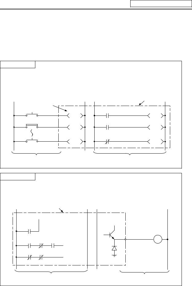
5.3.1 Input/output X, Y
Input/output X and Y are a window for executing communication with the PLC and external device or CNC.
Input X
(a)This issued commands or data from an external device such as a push-button, changeover switch, limit switch or digital switch to the PLC.
(b)Assuming that there is a hypothetical relay Xn built-in the PLC per input point, the program uses the "A" contact and "B" contact of that Xn.
(c)There is no limit to the No. of "A" contacts and "B" contacts of the input Xn that can be used in the program.
Hypothetical |
relay |
PLC |
|
||
PB1 |
X10 |
X10 |
LS2 |
X11 |
X11 |
PB16 |
X1F |
X1F |
|
Input circuit |
Program |
(d) The input No. is expressed with a hexadecimal.
Output Y
(a)This outputs the results of the program control to the solenoid, magnetic switch, signal lamp or digital indicator, etc.
(b)The output can be retrieved with the equivalent of one "A" contact.
(c)There is no limit to the No. of "A" contacts and "B" contacts of the output Yn that can be used in the program.
PLC
Y10


 24V Y10
Load
Y10
Y10
Program |
Output circuit |
(d)The output No. is expressed with a hexadecimal.
-16 -

5. Explanation of Devices
5.3.2 Internal Relays M and F, Latch Relay L
The internal relay and latch relay are auxiliary relays in the PLC that cannot directly output to an external source.
Internal relays M
(a)These relays are cleared when the power is turned OFF.
(b)There is no limit to the No. of "A" contacts and "B" contacts of the internal relays that can be used in the program.
(c)The internal relay No. is expressed with a decimal.
Internal relay F
Internal relay F is an interface for the alarm message display.
Use the bit selection parameter to determine whether to use this relay for the alarm message interface. The target will be F0 to F127. This internal relay can be used in the same manner as the internal relay M when not used as the alarm message interface.
Latch relay L
(a)The original state is held even when the power is turned OFF.
(b)There is no limit to the No. of "A" contacts and "B" contacts of the latch relay that can be used in the program.
(c)The latch No. is expressed with a decimal.
5.3.3 Special Relays SM
The special relays are relays having fixed applications such as the carrier flag for operation results and the display request signal to the setting and display unit. Even the relays of SM0 to SM127 that are not currently used must not be used as temporary memory.
Special relays SM
(a)This relay is cleared when the power is turned OFF.
(b)There is no limit to the No. of "A" contacts and "B" contacts of the special relays that can be used in the program.
(c)The special relay No. is expressed with a decimal.
- 17 -
5. Explanation of Devices
5.3.4Timer T
(1)The 100ms timer, 10ms timer and 100ms integrated timer are available for this count-up type timer.
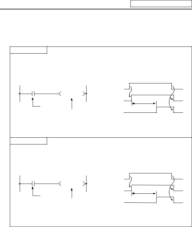
100ms Timer T
(a)When the input conditions are set, the count starts. When the set value is counted, that timer contact will turn ON.
(b)If the input conditions are turned OFF, the 100ms timer count value will be set to 0, and the contact will turn OFF.
|
|
|
ON |
|
X5 |
X5 |
OFF |
ON |
|
T57 K50 |
|
|
||
|
T57 coll |
OFF |
5 seconds |
|
Input conditions |
|
|||
|
|
ON |
||
100ms timer |
T57 contact |
OFF |
||
|
(c)When #6449 bit0=1, the value is set with a decimal (Kn), and can be designated from 1 to 32767 (0.1 to 3276.7 s). The data register (D) data can also be used as the setting value. File register (R) cannot be used.
10ms Timer T
(a)When the input conditions are set, the count starts. When the set value is counted, that timer contact will turn ON.
(b)If the input conditions are turned OFF, the 10ms timer count value will be set to 0, and the contact will turn OFF.
|
|
|
|
|
ON |
X5 |
|
|
X5 |
OFF |
ON |
|
T1 |
K500 |
|
|
|
|
|
|
|
||
|
|
|
T1 coll |
OFF |
5 seconds |
Input |
conditions |
|
|
|
ON |
|
10ms timer |
T1 contact |
OFF |
||
|
|
|
|
||
(c)When #6449 bit0=1, the value is set with a decimal (Kn), and can be designated from 1 to 32767 (0.01 to 327.67 s). The data register (D) data can also be used as the setting value. File register (R) cannot be used.
- 18 -
5. Explanation of Devices
100ms integrated timer T
(a)When the input conditions are set, the count starts. When the set value is counted, that timer contact will turn ON.
(b)Even the input conditions are turned OFF, the 100ms integrated timer current value (count value) will be held, and the contact state will not change.
(c)The 100ms integrated timer count value will be set to 0 and the contact will turn OFF when the RST command is executed.
X5 |
|
|
|
|
|
|
|
|
|
|
|
ON |
|
|
|
|
|
|
|
|
|
|
|
|
|
|
|
|
|
|
|
|
|
|
|
|
|
||||||
|
|
|
T233 K100 |
X5 OFF |
|
|
9 seconds |
|
|
|
|
|
|
|
|
|
|
|
|
|
|
|
|
|
|
|
|
|
|
||||||||||||||
|
|
|
|
|
|
|
|
|
|
|
|
|
|
|
|
|
|
|
|
|
|
|
|
|
|
|
|
|
|
|
|||||||||||||
|
|
|
|
|
|
|
|
|
|
|
|
|
|
|
|
|
|
|
|
|
|
|
|
|
|
|
|||||||||||||||||
|
|
|
|
|
|
|
|
|
|
|
|
|
|
|
|
|
|
|
|
|
|
|
|
|
|
|
|
|
|
|
|
|
|
|
|
|
|
|
|
|
|
|
|
|
|
|
|
Input conditions |
|
|
|
|
|
|
|
|
|
|
|
|
|
|
|
|
|
|
|
|
|
|
|
|
|
|
seconds |
|
|
|
|
|
|
||||||
|
|
|
|
|
|
|
|
|
|
|
|
|
|
|
|
|
|
|
1.5 seconds |
6 |
|
|
|
||||||||||||||||||||
|
|
|
|
|
|
|
|
|
|
|
|
|
|
|
|
||||||||||||||||||||||||||||
X7 |
|
100ms cumulative |
timer |
|
|
|
|
|
|
|
|
|
|
|
|
|
|
|
ON |
|
|
|
|
|
|
|
|
|
|
|
|
|
|
||||||||||
|
|
|
RST T233 |
|
|
|
X7 OFF |
|
|
|
|
|
|
|
|
|
|
|
|
|
|
|
|
|
|
|
|
|
|
|
|
|
|
|
|
|
|||||||
|
|
|
|
|
|
|
|
|
|
|
|
|
|
|
|
|
|
|
|
|
|
|
|
|
|
|
|
|
|
|
|
|
|
|
|
|
|
|
|||||
|
|
|
|
|
|
|
|
|
|
|
|
|
|
|
|
|
|
|
|
|
|
|
|
|
|
|
|
|
|
|
|
|
|
|
|
|
|
|
|||||
|
|
|
|
|
|
|
|
|
|
|
|
|
|
|
|
|
|
|
|
|
|
|
|
|
|
|
|
|
|
|
|
|
|
|
|
|
|
|
|
|
|||
|
|
|
|
|
|
|
|
|
|
|
|
|
|
|
|
|
|
|
|
|
|
|
|
|
|
|
|
|
|
|
|
|
|
|
|
|
|
|
|
|
|||
Reset input |
T233 reset command |
|
|
|
ON |
|
|
|
|
|
|
|
|
|
|
|
|
|
|
|
|
|
|
|
|
|
|
|
|
|
|||||||||||||
|
|
|
|
|
|
|
|
|
|
|
|
|
|
|
|
|
|
|
|
|
|
|
|
|
|
|
|
|
|
|
|
|
|||||||||||
|
|
|
|
|
|
|
|
T233 coll |
OFF |
|
|
9 seconds |
|
|
|
|
|
|
|
|
|
|
|
|
|
|
|
|
|
|
|
|
|
|
|||||||||
|
|
|
|
|
|
|
|
|
|
|
|
|
|
|
|
|
|
|
|
|
|
|
|
|
|
|
|
|
|
|
|
|
|
|
|
|
|||||||
|
|
|
|
|
|
|
|
|
|
|
|
|
|
|
|
|
|
|
|
|
|
1 |
|
|
|
|
6 |
|
seconds |
|
|
|
|
||||||||||
|
|
|
|
|
|
|
|
|
|
|
|
|
|
|
|
|
|
|
|
|
|
seconds |
|
|
|
||||||||||||||||||
|
|
|
|
|
|
|
|
|
|
|
|
|
|
|
|
|
|
|
|
|
|
|
|
|
ON |
|
|
|
|
|
|
|
|
|
|
|
|
|
|
||||
|
|
|
|
|
|
|
|
T233 contact OFF |
|
|
|
|
|
|
|
|
|
|
|
|
|
|
|
|
|
|
|
|
|
|
|
|
|
|
|
|
|
||||||
|
|
|
|
|
|
|
|
|
|
|
|
|
|
|
|
|
|
|
|
|
|
|
|
|
|
|
|
|
|
|
|
|
|
|
|
|
|||||||
|
|
|
|
|
|
|
|
|
|
|
|
|
|
|
|
|
|
|
|
|
|
|
|
|
|
||||||||||||||||||
|
|
|
|
|
|
|
T233 current value |
0 |
|
1 |
~ 90 |
|
91~ 100 |
|
0 |
|
|
1 ~ 60 |
|
|
|
|
|
|
|
|
|||||||||||||||||
|
|
|
|
|
|
|
|
|
|
|
|
|
|
|
|
|
|
|
|
||||||||||||||||||||||||
(d)When #6449 bit0=1, the value is set with a decimal (Kn), and can be designated from 1 to 32767 (0.1 to 3267.7 s). The data register (D) data can also be used as the setting value. File register (R) cannot be used.
(e)When the bit selection parameter (#6449 bit2=1) is set, the 100ms integrated timer current value (count value) will be held even when the power is turned OFF.
(2)With the device T, the contact • coil is handled as bit device, and the current value is handled as word device. In the function commands described after, the word device T indicates the current value even if there is no description about it.
(3)When #6449 bit0=0 is set, timer value can be specified with the parameter set in the setting and display unit. At this time, the relationship between timer device and parameter is as shown below.
Device |
Parameter |
T0 to T15 |
#6000 to #6015 |
T56 to T135 |
#6016 to #6095 |
T232 to T239 |
#6096 to #6103 |
(Note 1) T16 to T55, T136 to T231, and T240 to T255 are specified with a program (Kn) regardless of #6449 bit0.
(Note2) Even when #6449 bit0=0, Kn is required for a sequence program. Note that, however, the Kn value is invalid.
(Note 3) When the data register (D) is used as setting value, the data register (D) details will be the setting value regardless of #6449 bit0.
- 19 -
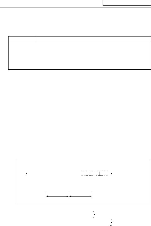
5. Explanation of Devices
5.3.5Counter C
(1)The counter counts up and detects the rising edge of the input conditions. Thus, the count will not take place when the input conditions are ON.
Counter C
(a)The value is set with a decimal, and can be designated from 1 to 32767. The data register (D) data can also be used as the setting value. File register (R) cannot be used.
(b)The counter count value will not be cleared even if the input conditions turn OFF. The counter count value must be cleared with the RST command.
(c)When the bit selection parameter is set, the counter current value (count value) will be held even when the power is turned OFF. Note that some can not be held depending on the version of CNC.
(2)With the device C, the contact • coil is handled as bit device, and the current value (counter value) is handled as word device. In the function commands described after, the word device C indicates the current value (counter value) even if there is no description about it.
(3)The counter setting value can be set with the setting and display unit using device C. (Variable counter)
Whether the setting value (Kn) programmed with the sequence program or the setting value set from the setting and display unit is valid is selected with the bit selection parameters. The changeover is made in a group for C0 to C23. Even when set from the setting and display unit, the setting value (Kn) program will be required in the sequence program. However, the Kn value will be ignored. When the data register (D) is used for the setting value, the data register (D) details will be used as the setting value regardless of the parameter.
(Note) The setting value for device C24 to C127 of counter C cannot be set from the setting and display unit.
5.3.6Data Register D
(1)The data register is the memory that stores the data in the PLC.
(2)The data register has a 1-point 16-bit configuration, and can be read and written in 16-bit units. To handle 32-bit data, two points must be used. The data register No. designated with the 32-bit command will be the low-order 16-bit, and the designated data register No. +1 will be the high-order 16-bit.
|
Circuit example |
|
|
|
|
|
|
|
|
|
|
|
||||
|
|
|
|
|
|
|
|
|
|
|
|
|
|
|
The X0 to 1F data is |
|
|
|
|
|
|
|
|
|
|
|
|
|
|
|
|
|
|
|
|
|
|
|
|
|
|
|
|
|
|
|
|
|
|
|
|
0 |
|
|
|
|
|
|
|
DMOV K8X0 |
D0 |
|
|
||||
|
|
|
|
|
|
|
|
|
stored in D0,1. |
|
||||||
|
|
|
|
|
|
|
|
|
|
|
|
|
|
|
|
|
|
|
|
|
|
|
|
|
|
|
|
|
|
|
|
|
|
|
|
|
|
|
|
|
|
|
|
|
|
|
|
|
|
|
|
Data storage |
|
|
|
|
|
|
|
|
|
|
|
||||
|
|
|
D1 |
D0 |
|
|
|
|
|
|
||||||
|
|
|
|
|
|
|
|
|
|
|
|
|
||||
|
|
|
|
|
|
|
|
|
|
|
||||||
|
|
|
|
|
|
|
|
|
|
|
|
|
|
|
|
|
Higth-order 16-bit Low-order 16-bit
(X1F~X10) (XF~X0)
(3)The data that is stored once in the sequence program is held until other data is stored.
(4)The data stored in the data register is cleared when the power is turned OFF.
(5) Values that can be stored: Decimal -32768 to 32767 |
For 16-bit command |
|
Hexadecimal 0 to FFFF |
(Using Dn) |
|
Decimal -2147483648 to 2147483647 |
For 32-bit command |
|
Hexadecimal 0 to FFFFFFFF |
|
(Using Dn+1, Dn) |
(6)Data registers D0 to D1023 are all user release data registers.
-20 -
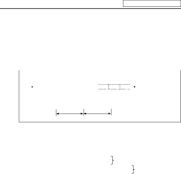
5. Explanation of Devices
5.3.7File Register R
(1)As with the data registers, the file registers are memories used to store data. However, there are some that have fixed applications, and those that are released.
(2)The file register has a 1-point 16-bit configuration, and can be read and written in 16-bit units. To handle 32-bit data, two points must be used. The file register No. designated with the 32-bit command will be the low-order 16-bit, and the designated file register No. +1 will be the high-order 16-bit.
(Example) Use of the DMOV command is shown below.
|
Circuit example |
|
|
|
|
|
|
|
|
|
|
|||
|
|
|
|
|
|
|
|
|
|
|
|
|
|
The X0 to 1F data is |
|
|
|
|
|
|
|
|
|
|
|
|
|
|
|
|
|
|
|
|
|
|
|
|
|
|
|
|
|
|
|
0 |
|
|
|
|
|
|
DMOV K8X0 |
R0 |
|
||||
|
|
|
|
|
|
|
|
stored in R0,1. |
||||||
|
|
|
|
|
|
|
|
|
|
|
|
|
|
|
|
|
|
|
|
|
|
|
|
|
|
|
|
|
|
|
|
|
|
|
|
|
|
|
|
|
|
|
|
|
|
Data storage |
|
|
|
|
|
|
|
|
|
|
|||
|
|
R1 |
R0 |
|
|
|
|
|
||||||
|
|
|
|
|
|
|
|
|
|
|
||||
|
|
|
|
|
|
|
|
|
||||||
|
|
|
|
|
|
|
|
|
|
|
|
|
|
|
Higth-order 16-bit Low-order 16-bit
(X1F~X10) (XF~X0)
(3)The data that is stored once in the sequence program is held until other data is stored.
(4)With the file registers, the following registers are the user release.
R500 to R549, R1900 to R2799
The following registers of the registers above are not cleared when the power is turned OFF. R1900 to R2799
The other file registers have fixed applications such as interface of the PLC and CNC, parameter
interface, etc. |
|
|
(5) Values that can be stored: Decimal -32768 to 32767 |
For 16-bit command |
|
Hexadecimal 0 to FFFF |
(Using Dn) |
|
Decimal -2147483648 to 2147483647 |
For 32-bit command |
|
Hexadecimal 0 to FFFFFFFF |
|
(Using Dn+1, Dn) |
- 21 -
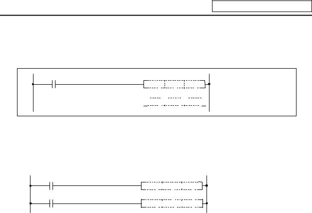
5. Explanation of Devices
5.3.8Index Registers Z
(1)The index registers are used as ornaments for the device (T, C, D, R).
159 |
MOV K3 Z0 |
165 


 MOV
MOV

 K4X0
K4X0

 D5Z0
D5Z0
 D5Z0 Indicates D (5+Z) = D8
(2)The index register has a 1-point 16-bit configuration, and can be read and written in 16-bit units.
(3)The data stored in the index register is cleared when the power is turned OFF.
(4)Values that can be stored: Decimal -32768 to 32767
Hexadecimal 0 to FFFF
(Note) The CRT display of the index registers Z is as shown below.
MOV  K3
K3  Z0
Z0
K4 Z0
MOV  X0
X0  D5
D5
- 22 -
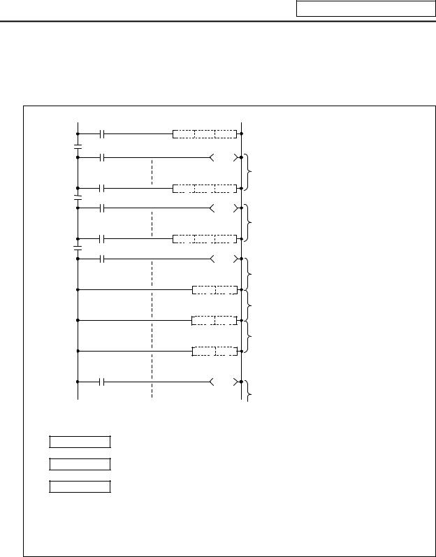
5. Explanation of Devices
5.3.9Nesting N
(1)This indicates the master control nesting structure.
(2)The master control nesting (N) is used in order from smallest number.
|
A |
|
|
|
MC N0 |
M15 |
|
N0 |
M15 |
|
|
|
B |
|
Execute when A conditions are set. |
|
|
|
|
|
MC N1 M16 |
|
|
N1 |
M16 |
|
|
|
C |
|
Execute when A,B conditions are set. |
|
|
|
|
N2 |
MC N2 M17 |
|
|
M17 |
|
|
|
|
|
|
Execute when A,B,C conditions are set. |
|
MCR |
N2 |
Reset MC2 to 7 |
|
|
|
|
|
|
|
Execute when A,B conditions are set. |
|
MCR |
N1 |
Reset MC1 to 7 |
|
|
|
|
|
|
|
Execute when A conditions are set. |
|
MCR |
N0 |
Reset MC0 to 7 |
|
|
|
|
|
|
|
Execute regardless of A,B,C conditions. |
(a)The conditions for each master control to turn ON are as follow. MC N0 M15 .......... ON when condition A is ON
MC N1 M16 .......... ON when conditions A, B are ON MC N2 M17 .......... ON when conditions A, B, C are ON
(b)The timer and counter when the master control is OFF is as follows.
· 100ms timer, 10ms timer |
: The count value is set to 0. |
· 100ms integrated timer |
: The current count value is retained. |
· Counter |
: The current counter value is retained. |
· OUT command |
: All turn OFF. |
- 23 -
Loading...