


English
Deutsch
Español
Français
Italiano
Nederlands
English
Deutsch
Español
Français
Nederlands Italiano

Index
Important Information ................................................................................................................................... |
English-2 |
Safety Precautions, Maintenance & Recommended Use ............................................................................ |
English-4 |
Contents ....................................................................................................................................................... |
English-5 |
Parts Name and Functions .......................................................................................................................... |
English-6 |
Control Panel .................................................................................................................................. |
English-6 |
Terminal Panel ................................................................................................................................ |
English-7 |
Wireless Remote Control ............................................................................................................... |
English-8 |
Operating Range for the Remote Control ....................................................................................... |
English-9 |
Handling the remote control ........................................................................................................... |
English-9 |
Setup Procedure .......................................................................................................................................... |
English-10 |
How to Mount and Attach Options to the LCD Monitor ................................................................................ |
English-12 |
Connections ................................................................................................................................................. |
English-13 |
Wiring Diagram ............................................................................................................................... |
English-13 |
Connecting a Personal Computer .................................................................................................. |
English-14 |
Connecting with Digital Interface Equipment .................................................................................. |
English-15 |
Connecting a DVD Player with component out ............................................................................... |
English-16 |
Connecting to a Stereo Amplifier .................................................................................................... |
English-17 |
Basic Operation ............................................................................................................................................ |
English-18 |
Power ON and OFF Modes ............................................................................................................ |
English-18 |
Power Indicator ............................................................................................................................... |
English-19 |
Using Power Management ............................................................................................................. |
English-19 |
Selecting a video source ................................................................................................................ |
English-19 |
Picture Size .................................................................................................................................... |
English-19 |
Picture Mode .................................................................................................................................. |
English-19 |
Information OSD ............................................................................................................................. |
English-19 |
OSD (On-Screen-Display) Controls ............................................................................................................. |
English-20 |
PICTURE ........................................................................................................................................ |
English-20 |
SCREEN ......................................................................................................................................... |
English-21 |
AUDIO ............................................................................................................................................ |
English-22 |
PICTURE IN PICTURE .................................................................................................................. |
English-23 |
CONFIGURATION 1 ....................................................................................................................... |
English-23 |
CONFIGURATION 2 ....................................................................................................................... |
English-25 |
ADVANCED OPTION ..................................................................................................................... |
English-26 |
NOTE .............................................................................................................................................. |
English-27 |
Controlling the LCD monitor via RS-232C Remote Control ......................................................................... |
English-29 |
Features ....................................................................................................................................................... |
English-31 |
Troubleshooting ........................................................................................................................................... |
English-32 |
Specifications (LDT321V) ............................................................................................................................ |
English-33 |
Specifications (LDT371V) ............................................................................................................................ |
English-34 |
Pin Assignment ............................................................................................................................................ |
English-35 |
English
English-1
Important Information
DECLARATION OF CONFORMITY
This device complies with Part 15 of FCC Rules. Operation is subject to the following two conditions. (1) This device may not cause harmful interference, and (2) this device must accept any interference received, including interference that may cause undesired operation.
U.S. Responsible Party: |
Mitsubishi Digital Electronics America, Inc. |
Address: |
9351 Jeronimo Road, |
|
Irvine, California 92618 U.S.A. |
Tel. No.: |
+1 - (949) 465-6000 |
|
|
Type of Product: |
Computer Monitor |
Equipment Classification: |
Class B Peripheral |
Model: |
LDT321V (BH548) / LDT371V (BJ544) |
We hereby declare that the equipment specified above
conforms to the technical standards as specified in the FCC Rules.
Windows is a registered trademark of Microsoft Corporation. All other brands and product names are trademarks or registered trademarks of their respective owners.
Canadian Department of Communications Compliance Statement
DOC: This Class B digital apparatus meets all requirements of the Canadian Interference-Causing Equipment Regulations.
C-UL: Bears the C-UL Mark and is in compliance with Canadian Safety Regulations according to CAN/CSA C22.2 No. 60950-1.
FCC Information
1.Use the attached specified cables with the LDT321V (BH548) / LDT371V (BJ544) color monitor so as not to interfere with radio and television reception.
(1)Please use the supplied power cord or equivalent to ensure FCC compliance.
(2)Please use the supplied shielded video signal cable, 15-pin mini D-SUB to 15-pin mini D-SUB.
2.This equipment has been tested and found to comply with the limits for a Class B digital device, pursuant to part 15 of the FCC Rules.
These limits are designed to provide reasonable protection against harmful interference in a residential installation. This equipment generates, uses, and can radiate radio frequency energy, and, if not installed and used in accordance with the instructions, may cause harmful interference to radio communications. However, there is no guarantee that interference will not occur in a particular installation. If this equipment does cause harmful interference to radio or television reception, which can be determined by turning the equipment off and on, the user is encouraged to try to correct the interference by one or more of the following measures:
• Reorient or relocate the receiving antenna.
• Increase the separation between the equipment and receiver.
• Connect the equipment into an outlet on a circuit different from that to which the receiver is connected.
• Consult your dealer or an experienced radio/TV technician for help.
If necessary, the user should contact the dealer or an experienced radio/television technician for additional suggestions. The user may find the following booklet, prepared by the Federal Communications Commission, helpful: “How to Identify and Resolve Radio-TV Interference Problems.” This booklet is available from the U.S. Government Printing Office, Washington, D.C., 20402, Stock No. 004-000-00345-4.
English-2
Important Information
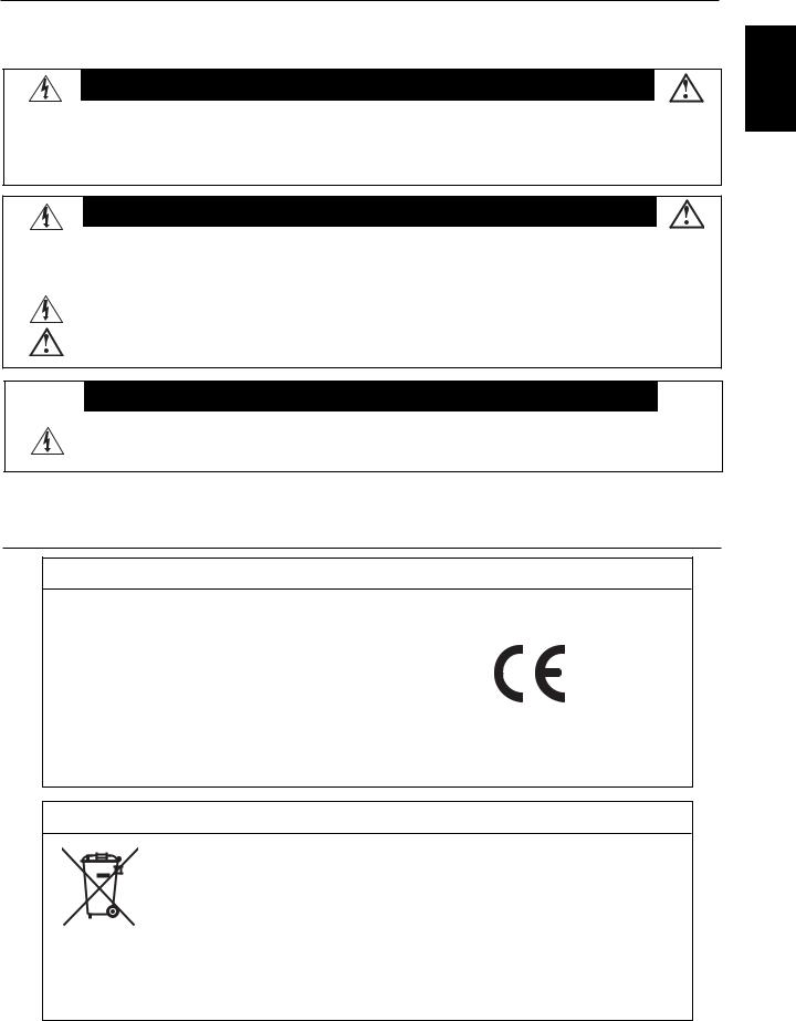
WARNING
TO PREVENT FIRE OR SHOCK HAZARDS, DO NOT EXPOSE THIS UNIT TO RAIN OR MOISTURE. ALSO, DO NOT USE THIS UNIT’S POLARIZED PLUG WITH AN EXTENSION CORD RECEPTACLE OR OTHER OUTLETS UNLESS THE PRONGS CAN BE FULLY INSERTED.
REFRAIN FROM OPENING THE CABINET AS THERE ARE HIGH VOLTAGE COMPONENTS INSIDE. REFER SERVICING TO QUALIFIED SERVICE PERSONNEL.
CAUTION
CAUTION |
TO REDUCE THE RISK OF ELECTRIC SHOCK, MAKE SURE POWER CORD IS UNPLUGGED FROM |
|
|
|
WALL SOCKET. TO FULLY DISENGAGE THE POWER TO THE UNIT, PLEASE DISCONNECT THE |
|
POWER CORD FROM THE AC OUTLET. DO NOT REMOVE COVER (OR BACK). NO USER |
|
SERVICEABLE PARTS INSIDE. REFER SERVICING TO QUALIFIED SERVICE PERSONNEL. |
|
This symbol warns user that uninsulated voltage within the unit may have sufficient magnitude to cause |
|
electric shock. Therefore, it is dangerous to make any kind of contact with any part inside this unit. |
|
This symbol alerts the user that important literature concerning the operation and maintenance of this unit |
|
has been included. Therefore, it should be read carefully in order to avoid any problems. |
CAUTION
This LCD Monitor uses a lamp that contains mercury. Disposal of the lamp or the LCD Monitor with the lamp may be regulated due to environmental considerations. For disposal or recycling information, please contact your local authorities or the Electronic Industries Alliance: www.eiae.org. (For US only).
Declaration
Declaration of the Manufacturer
We hereby certify that the color monitor LDT321V(BH548)/ LDT371V(BJ544) is in compliance with
Council Directive 73/23/EEC:
– EN 60950-1
Council Directive 89/336/EEC:
–EN 55022
–EN 61000-3-2
–EN 61000-3-3
–EN 55024
and marked with
Mitsubishi Electric Corporation
2-7-3, Marunouchi,
Chiyoda-Ku
Tokyo 100-8310, Japan
Declaration of the Manufacturer
Note: This symbol mark is EU countries only.
This symbol mark is according to the directive 2002/96/EC Article 10 Information for users and Annex IV.
Your MITSUBISHI ELECTRIC product is designed and manufactured with high quality materials and components which can be recycled and reused.
This symbol means that electrical and electronic equipment, at their end-of-life, should be disposed of separately from your household waste.
Please, dispose of this equipment at your local community waste collection/recycling center.
In the European Union there are separate collection systems for used electrical and electronic product. Please, help us to conserve the environment we live in!
English
English-3

Safety Precautions, Maintenance & Recommended Use
FOR OPTIMUM PERFORMANCE, PLEASE NOTE THE FOLLOWING WHEN SETTING UP AND USING THE LCD COLOR MONITOR:
•DO NOT OPEN THE MONITOR. There are no user serviceable parts inside and opening or removing covers may expose you to dangerous shock hazards or other risks.
Refer all servicing to qualified service personnel.
•Do not spill any liquids into the cabinet or use your monitor near water.
•Do not insert objects of any kind into the cabinet slots, as they may touch dangerous voltage points, which can be harmful or fatal or may cause electric shock, fire or equipment failure.
•Do not place any heavy objects on the power cord. Damage to the cord may cause shock or fire.
•Do not place this product on a sloping or unstable cart, stand or table, as the monitor may fall, causing serious damage to the monitor.
•When operating the LCD monitor with an AC 100-120V power supply in North America, use a power supply cord provided with this monitor.
•When operating the LCD monitor with an AC 220-240V power supply in Europe, use a power supply cord provided with this monitor.
•In UK, use a BS-approved power cord with molded plug having a black (10A) fuse installed for use with this monitor.
If a power cord is not supplied with this monitor, please contact your supplier.
•When operating the LCD monitor with a 220-240V AC power supply in Australia, use the power cord provided with this monitor.
If a power cord is not supplied with this monitor, please contact your supplier.
•For all othercase, use a power cord that matches the AC voltage of the power outlet and has been approved by and complies with the safety standard of your particular country.
•Do not place any objects onto the monitor and do not use the monitor outdoors.
•The inside of the fluorescent tube located within the LCD monitor contains mercury. Please follow the laws or rules of your municipality to dispose of the tube properly.
•Do not bend power cord.
•Do not use monitor in high temperature, humid, dusty, or oily areas.
•If monitor or glass is broken, do not come in contact with the liquid crystal and handle with care.
•Allow adequate ventilation around the monitor, so that heat can properly dissipate. Do not block ventilated openings or place the monitor near a radiator or other heat sources.
Do not put anything on top of the monitor.
•The power cable connector is the primary means of detaching the system from the power supply. The monitor should be installed close to a power outlet, which is easily accessible.
•Handle with care when transporting. Save packaging for transporting.
•Please clean the holes of back cabinet to reject dirt and dust at least once a year because of set reliability.
•If using the cooling fan continuously, it’s recommended to wipe holes a minimum of once a month.
•When installing the remote control batteries;
-Align the batteries according to the (+) and (-) indications inside the case.
-Align the (-) indication of the battery first inside the case.
CAUTION
Immediately unplug your monitor from the wall outlet and refer servicing to qualified service personnel under the following conditions:
•When the power supply cord or plug is damaged.
•If liquid has been spilled, or objects have fallen into the monitor.
•If the monitor has been exposed to rain or water.
•If the monitor has been dropped or the cabinet damaged.
•If the monitor does not operate normally by following operating instructions.
Recommended Use
CAUTION
•For optimum performance, allow 20 minutes for warm-up.
•Rest your eyes periodically by focusing on an object at least 5 feet away. Blink often.
•Position the monitor at a 90° angle to windows and other light sources to minimize glare and reflections.
•Clean the LCD monitor surface with a lint-free, nonabrasive cloth. Avoid using any cleaning solution or glass cleaner!
•Adjust the monitor’s brightness, contrast and sharpness controls to enhance readability.
•Avoid displaying fixed patterns on the monitor for long periods of time to avoid image persistence (after image effects).
•Get regular eye checkups.
Ergonomics
To realize the maximum ergonomic benefits, we recommend the following:
•Use the preset Size and Position controls with standard signals.
•Use the preset Color Setting.
•Use non-interlaced signals.
•Do not use primary color blue on a dark background, as it is difficult to see and may produce eye fatigue due to insufficient contrast.
English-4
Contents
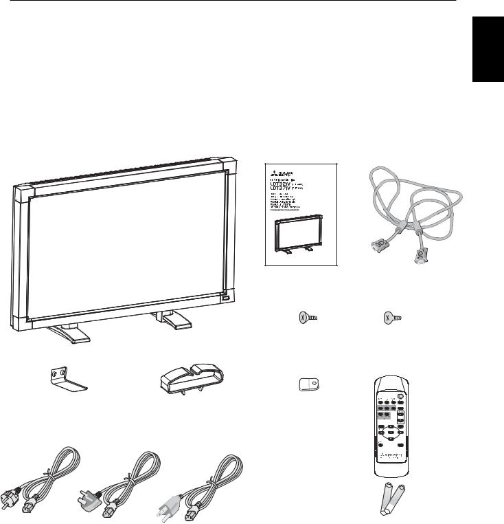
Your new LDT321V/LDT371V monitor box* should contain the following:
• |
LCD monitor |
Main switch cover |
|
• |
|
• |
Power Cord (3m) |
Screw for Main Switch cover x 2 |
|
• |
|
• |
Video Signal Cable (4m) |
Cable Holder |
|
• |
•User’s Manual
•Wireless Remote Control and AAA Batteries
•Clamper x 2
•Screw for Clamper x 2
English
Main switch cover |
Cable Holder |
* The supplied power cord varies depending on destination.
User’s Manual |
Video Signal Cable |
|
(D-SUB to D-SUB Cable) |
Screw for Main switch cover |
Screw for Clamper |
(M3 x 10) x 2 |
(M4 x 8) x 2 |
Clamper x 2
For EU |
For UK |
For North |
|
|
America |
Power cord
*For all other case, use a power cord that matches the AC voltage of the power outlet and has been approved by and complies with the safety standard of your particular country.
* Remember to save your original box and packing material to transport or ship the monitor.
The following components are prepared as option.
• External Speakers
Wireless Remote Control
and AAA Batteries
English-5
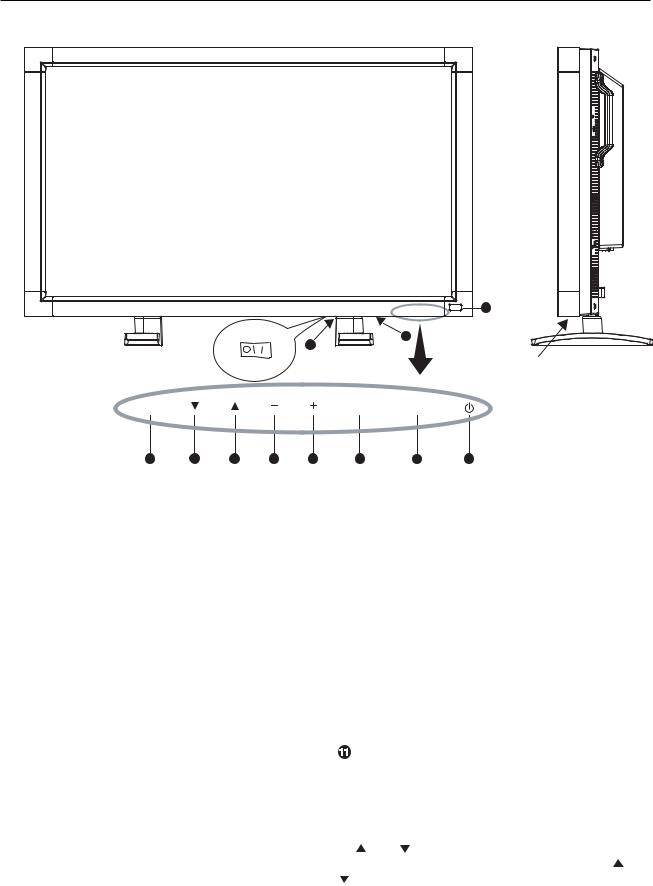
Parts Name and Functions
Control Panel
OFF |
ON |
11 |
|
EXIT
8 |
7 |
6 |
5 |
4 |
 POWER button (
 )
)
Switches the power on/off. See also page 18.
 MUTE button
Switches the audio mute ON/OFF.
 INPUT button
Acts as SET button with OSD menu.
(Toggle switches between [RGB1], [RGB2], [RGB3], [DVD/HD], [VIDEO<S>] and [VIDEO] .)
 PLUS (+) button
Acts as (+) button to increase the adjustment with OSD menu. Increase the audio output level when the OSD menu is turned off.
 MINUS (-) button
Acts as (-) button to decrease the adjustment with OSD menu. Decreases the audio output level when the OSD menu is turned off.
 UP (
UP ( ) button
Activates the OSD menu when the OSD menu is turned-off. Acts as  button to move the highlighted area up to select the adjustment with OSD menu.
 DOWN (
 ) button
Activates the OSD menu when the OSD menu is turned-off. Acts as  button to move the highlighted area down to select the adjustment with OSD menu.
9
10
Button Location
INPUT MUTE
3 |
2 |
1 |
 EXIT button
Activates the OSD menu when the OSD menu is turned-off. Acts as EXIT button to move to previous menu with OSD menu.
 Remote control sensor and Power indicator
Receives the signal from the remote control (when using the wireless remote control). See also page 9.
Glows green when the LCD monitor is in active and glows red when the LCD is in POWER OFF mode. When the LCD is in power save mode, it will glow both green and red. When SCHEDULE is enabled, it willl blink green and glow red. See page 19. In the case of where a failure is detected, it will blink red.
 Main Power Switch (LDT371V)
Main Power Switch (LDT321V)
On/Off Switch to turn main power on/off.
NOTE: Control Key Lock Mode
This control completely locks out access to all Control Key functions. To activate the control key lock function, press both of “ “ and “ “ and hold down simultaneously for more than 3 seconds. To resume back to user mode, press both of “ “ and
““ and hold simultaneously for three (3) seconds.
English-6
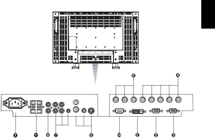
Terminal Panel
AC IN |
Speaker |
AUDIO |
OUT |
|
|
OUT |
|
||
|
OUT 3 2 |
|
||
|
|
|
||
|
|
|
S-VIDEO |
|
|
|
|
1 IN |
|
|
|
|
IN IN |
|
|
R L |
|
|
VIDEO |
 AC IN connector
Connects with the supplied power cord.
 RGB 1 IN (DVI-D)
To input digital RGB signals from a computer.
* This connector does not support analog input.
 RGB 2 IN (mini D-Sub 15 pin)
To input a analog RGB signals from a computer or other RGB equipment.
 RGB 3 IN [R, G, B, H, V] (BNC)
To input the analog RGB signals from a computer or other RGB equipment.
 RGB OUT (mini D-Sub 15 pin)
To output the signal from RGB 2 IN or 3 IN.
 DVD/HD IN [Y, Pb/Cb, Pr/Cr] (BNC)
Connecting equipment such as a DVD player, HDTV device, or Laser disc player.
English
Y Pb/Cb Pr/Cr |
R |
G |
B |
H |
V |
DVD/HD |
|
|
RGB3 |
|
|
RS-232C |
RGB1 |
RGB OUT |
RGB2 |
|
|
 AUDIO IN 1, 2, 3
To input audio signal from external equipment such as a computer, VCR or DVD player.
 AUDIO OUT
To output the audio signal from the AUDIO IN 1,2 and 3 jack.
 VIDEO IN/OUT
VIDEO IN connector (BNC and RCA): To input a composite video signal. BNC and RCA are not available at the same time.
(Use only one input).
VIDEO OUT connector (BNC): To output the composite video signal from VIDEO IN connector.
S-VIDEO IN connector (MINI DIN 4 pin): To input the S-
video (Y/C separate signal).
 EXTERNAL CONTROL (mini D-Sub 9 pin)
Use when operating the LCD monitor from RGB equipment like a computer. See page 29.
 EXTERNAL SPEAKER TERMINAL
To output the audio signal for external speakers from AUDIO 1, 2 or 3 jack.
English-7
Wireless Remote Control
 POWER button
Switches the power on/off.
* If Power Indicator is not glowing, then no controls will work.
 INPUT button
Selects from input signal, [RGB1], [RGB2], [RGB3], [DVD/ HD], [VIDEO<S>] and [VIDEO].
 AUDIO INPUT button
Selects from input audio signal, [AUDIO1], [AUDIO2], [AUDIO3]
 SIZE button
Selects picture size, [FULL], [NORMAL], [CUSTOM] , [DYNAMIC] and [REAL]. See page 19.
 PICTURE MODE button
Selects from picture mode, [HIGHBRIGHT], [STANDARD], [sRGB], [CINEMA]. See page 19.
HIGHBRIGHT: for moving image such as DVD STANDARD: for images (Factory setting) sRGB: for text based images
CINEMA: for movies.
 MUTE button
To switch the mute function on/off.
 VOLUME UP button
Increase the audio output level.
 VOLUME DOWN button
Decrease the audio output level.
PIP (Picture In Picture) button
ON/OFF button: PIP-ON/OFF.
See page 23.
INPUT button: Select the ‘picture in picture’ input signal. CHANGE button: Replaces to the main picture and sub picture.
Note: The "PIP" and "POP" modes do not function when the screen size is "CUSTOM" or "REAL"
 STILL button
ON/OFF button: To switch the still picture mode on/off. CAPTURE button: Updates the still picture.
 DISPLAY button
To switch the information OSD on/off. See page 19.
AUTO SETUP button
To enter the auto setup menu. See page 23.
 MENU button
To switch the menu mode on/off.
UP button
Acts as  button to move the highlighted area up to select the adjustment with OSD menu.
Small screen which adjusted “PIP” mode moves up.
DOWN button
Acts as  button to move the highlighted area down to select the adjustment with OSD menu.
Small screen which adjusted “PIP” mode moves down.
MINUS button decrease
Acts as (-) button to decrease the adjustment with OSD menu.
Small screen which adjusted “PIP” mode moves left.
PLUS button increase
Acts as (+) button to increase the adjustment with OSD menu.
Small screen which adjusted “PIP” mode moves right.
 SET button
Acts as SET button with OSD menu.
EXIT button
Turn to previous menu with OSD menu.
English-8
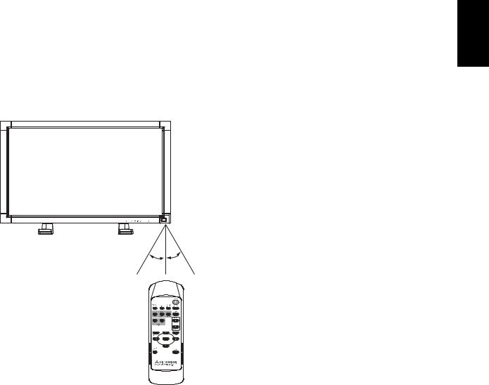
Operating Range for the Remote Control Handling the remote control
Point the top of the remote control toward the LCD monitor's remote sensor during button operation.
Use the remote control within a distance of about 7 m/23 ft. from the front of the LCD monitor's remote control sensor and at a horizontal and vertical angle of within 30° within a distance of about 3 m/10 ft.
*Do not subject to strong shock.
*Do not allow water or other liquid to splash the remote control. If the remote control gets wet, wipe it dry immediately.
*Avoid exposure to heat and steam.
*Other than to install the batteries, do not open the remote.
English
30o 30o
Caution
Important, the remote control system may not function when direct sunlight or strong illumination strikes the remote control sensor of the LCD monitor, or when there is an object in the path.
English-9
 Loading...