


 Loading...
Mitsubishi Electronics A1SD75M1, AD75M1, A1SD75P1-S3, AD75P1-S3, AD75P1 User Manual
...
• SAFETY PRECAUTIONS •
(Always read these instructions before using this equipment.)
Before using this product, please read this manual and the relevant manuals introduced in this manual carefully and pay full attention to safety to handle the product correctly.
The instructions given in this manual are concerned with this product. For the safety instructions of the programmable controller system, please read the CPU module User's Manual.
In this manual, the safety instructions are ranked as "DANGER" and "CAUTION".
!DANGER
!CAUTION
Indicates that incorrect handling may cause hazardous conditions, resulting in death or severe injury.
Indicates that incorrect handling may cause hazardous conditions, resulting in medium or slight personal injury or physical damage.
Note that the ! CAUTION level may lead to a serious consequence according to the circumstances. Always follow the instructions of both levels because they are important to personal safety.
Please save this manual to make it accessible when required and always forward it to the end user.
[Startup/Maintenance Instructions]
!CAUTION
•Before performing the Original Position Return, JOG operation, positioning data or other test in the test mode, read the manual carefully, fully ensure safety, and set the programmable controller CPU to STOP.
Not doing so can damage the machine or cause an accident due to misoperation.
A - 1 |
A - 1 |

REVISIONS
|
|
|
|
* The manual number is given on the bottom left of the back cover. |
|
Print Date |
* Manual Number |
|
|
|
Revision |
Mar., 1999 |
IB (NA)-66900-A |
First edition |
|||
Jun., 2000 |
IB (NA)-66900-B |
|
|
|
|
Correction |
|||||
|
|
Packing List, Section 12.8.2 |
|||
Jun., 2001 |
IB (NA)-66900-C |
The product name has been changed to GX Configurator-AP. |
|||
|
|
Correction |
|
|
|
|
|
About the Generic Terms and Abbreviations, Packing List |
|||
Aug., 2001 |
IB (NA)-66900-D |
|
|
|
|
Correction |
|||||
|
|
CONTENTS, About the Generic Terms and Abbreviations, Packing List, |
|||
|
|
Chapter 1, Section 2.1, Section 2.2, Section 3.1, Chapter 4 to 6, |
|||
|
|
Section 7.2, Section 8.2, Section 12.4.5, Section 12.11, Appendix 1, |
|||
|
|
INDEX |
|||
Nov., 2001 |
IB (NA)-66900-E |
|
|
|
|
Correction |
|||||
|
|
Section 8.2.3, Appendix 2.3, Appendix 2.4 |
|||
Feb., 2003 |
IB (NA)-66900-F |
|
|
|
|
New addition |
|||||
|
|
SOFTWARE USER REGISTRATION |
|||
|
|
Correction |
|
||
|
|
INTRODUCTION, CONTENTS, Section 2.2, Section 4.1, Section 4.2, |
|||
|
|
Section 4.3, Appendix 2.3, Appendix 2.4, INDEX |
|||
Feb., 2004 |
IB (NA)-66900-G |
|
|
|
|
Correction |
|||||
|
|
SOFTWARE USER REGISTRATION, Section 2.1 |
|||
Jan., 2008 |
IB(NA)- 66900-H |
|
|
|
|
Correction |
|||||
|
|
About the Generic Terms and Abbreviations, Section 2.2, Section 4.1, |
|||
|
|
Section 4.3, Appendix 2.4 |
|||
|
|
|
|
|
|
|
|
|
|
|
Japanese Manual Version IB-80031-I |
This manual confers no industrial property rights or any rights of any other kind, nor does it confer any patent licenses. Mitsubishi Electric Corporation cannot be held responsible for any problems involving industrial property rights which may occur as a result of using the contents noted in this manual.
♥ 1999 MITSUBISHI ELECTRIC CORPORATION
A - 2 |
A - 2 |
—— SOFTWARE USER REGISTRATION ——
After agreeing to the terms of the Software License Agreement included in the package, please access the MELFANSweb Home Page (http://www.MitsubishiElectric.co.jp/melfansweb) and make a software user registration. (User registration is free of charge.)
You can also make a registration by faxing or mailing the "Software Registration Card" packed with the product.
1.Software Registration
You can make a software registration by accessing the MELFANSweb Home Page or faxing or mailing the "Software Registration Card" packed with the product.
After you have made a software registration, we will register the user and send the "Software registration confirmation" together with the user ID.
We will also provide the latest information, such as the new product release, version upgrade information and event information, by direct mail.
2.Notes on Contact
Please ask questions concretely and clearly using terms listed in the manual.
When requesting us to solve a problem, provide us with detailed information for reproducing the problem.
In addition, contact the respective manufacturers when asking questions about the operating system (OS) or the other vender's software products
User registration is valid only in Japan.
A - 3 |
A - 3 |
INTRODUCTION
Thank you for choosing the Mitsubishi MELSOFT Series Integrated FA software.
Read this manual and make sure understand the functions and performance of MELSOFT series thoroughly in advance to ensure correct use.
|
CONTENTS |
|
|
SAFETY PRECATIONS ................................................................................................................................ |
A- 1 |
||
REVISIONS.................................................................................................................................................... |
A- 2 |
||
SOFTWARE USER REGISTRATION........................................................................................................... |
A- 3 |
||
INTRODUCTION............................................................................................................................................ |
A- 4 |
||
CONTENTS.................................................................................................................................................... |
A- 4 |
||
About Manuals ............................................................................................................................................... |
A- 8 |
||
How to Use This Manual................................................................................................................................ |
A- 9 |
||
About the Generic Terms and Abbreviations ................................................................................................ |
A-11 |
||
Packing List .................................................................................................................................................... |
A-11 |
||
|
|
||
1. OVERVIEW |
1- 1 to 1- 8 |
||
1.1 |
Features ................................................................................................................................................... |
1- |
2 |
1.2 Manual Makeup........................................................................................................................................ |
1- 7 |
||
|
|
||
2. SYSTEM CONFIGURATION |
2- 1 to 2- 5 |
||
2.1 |
System Configuration............................................................................................................................... |
2- |
1 |
2.2 |
Operating Environment............................................................................................................................ |
2- 4 |
|
|
|
||
3. FUNCTION LIST |
3- 1 to 3- 3 |
||
3.1 |
Function List ............................................................................................................................................. |
3- |
1 |
|
|
||
4. INSTALLATION AND UNINSTALLATION |
4- 1 to 4-12 |
||
4.1 |
Installation ................................................................................................................................................ |
4- |
1 |
4.2 |
Uninstallation............................................................................................................................................ |
4- |
8 |
4.3 |
Starting GX Configurator-AP ................................................................................................................... |
4-10 |
|
4.4 |
Ending GX Configurator-AP..................................................................................................................... |
4-11 |
|
|
|
||
5. SCREEN MAKEUP AND BASIC OPERATIONS |
5- 1 to 5- 4 |
||
5.1 |
Screen Makeup ........................................................................................................................................ |
5- 1 |
|
5.2 |
Basic Operations...................................................................................................................................... |
5- |
2 |
A - 4 |
A - 4 |
6. PROJECT CREATION |
6- 1 to 6-11 |
||
6.1 |
Creating a New Project ............................................................................................................................ |
6- |
2 |
6.2 |
Opening the Existing Project ................................................................................................................... |
6- |
4 |
6.3 |
Saving the Project .................................................................................................................................... |
6- |
5 |
6.4 |
Deleting the Project.................................................................................................................................. |
6- |
6 |
6.5 |
Reading the Other Format File (Import file) ............................................................................................ |
6- |
7 |
6.5.1 Reading the SW1 -AD75P format file.............................................................................................. |
6- 7 |
||
6.5.2 Reading the CSV format file ............................................................................................................. |
6- |
8 |
|
6.6 |
Write to Other Format File (Export file) ................................................................................................... |
6-10 |
|
6.6.1 Saving in SW1 -AD75P format file................................................................................................... |
6-10 |
||
6.6.2 Saving in CSV format file .................................................................................................................. |
6-11 |
||
|
|
||
7. SYSTEM CHECKING FROM PERIPHERAL DEVICE |
7- 1 to 7-16 |
||
7.1 |
Checking the AD75 Module Version (OS Information)........................................................................... |
7- 2 |
|
7.2 AD75P Checking Connect....................................................................................................................... |
7- 3 |
||
7.3 |
AD75M Servo Starting Up ....................................................................................................................... |
7- 6 |
|
7.3.1 Servo initial check ............................................................................................................................. |
7- |
7 |
|
7.3.2 Servo model name check ................................................................................................................. |
7- 9 |
||
7.3.3 Servo upper/lower limit check........................................................................................................... |
7-11 |
||
7.3.4 Servo speed check............................................................................................................................ |
7-14 |
||
|
|
||
8. PARAMETER SETTING |
8- 1 to 8-12 |
||
8.1 |
Parameters............................................................................................................................................... |
8- 1 |
|
8.1.1 Basic parameter 1 setting screen ..................................................................................................... |
8- |
3 |
|
8.1.2 Basic parameter 2 setting screen ..................................................................................................... |
8- |
4 |
|
8.1.3 Extended parameter 1 setting screen .............................................................................................. |
8- |
5 |
|
8.1.4 Extended parameter 2 setting screen .............................................................................................. |
8- |
6 |
|
8.1.5 OPR basic parameter setting screen ............................................................................................... |
8- |
7 |
|
8.1.6 OPR extended parameter setting screen......................................................................................... |
8- 8 |
||
8.2 |
Servo Parameters .................................................................................................................................... |
8- 9 |
|
8.2.1 Servo basic parameter setting screen.............................................................................................. |
8-10 |
||
8.2.2 Servo adjustment parameter setting screen .................................................................................... |
8-11 |
||
8.2.3 Servo extension parameter setting screen....................................................................................... |
8-12 |
||
|
|
||
9. SETTING OF POSITIONING DATA AND START BLOCK DATA |
9- 1 to 9-14 |
||
9.1 |
Positioning Data Setting........................................................................................................................... |
9- |
1 |
9.2 |
Positioning Data Checking....................................................................................................................... |
9- |
4 |
9.2.1 Error check ........................................................................................................................................ |
9- |
4 |
|
9.2.2 Offline simulation............................................................................................................................... |
9- |
6 |
|
9.3 |
Start Block Data Setting........................................................................................................................... |
9- |
8 |
9.4 |
Condition Data Setting ............................................................................................................................. |
9-10 |
|
9.5 |
Indirect Data Setting................................................................................................................................. |
9-12 |
|
9.6 M Code Comment Setting ....................................................................................................................... |
9-13 |
||
A - 5 |
A - 5 |
|
|
10. POSITIONING MODULE DATA WRITE/READ/VERIFY |
10- 1 to 10- 5 |
|||
10.1 Write to AD75/Read from AD75/Verify AD75 Data............................................................................. |
10- 1 |
|||
10.2 |
Flash ROM write/read request to AD75 .............................................................................................. |
10- 5 |
||
|
|
|||
11. POSITIONING DEBUGGING |
11- 1 to 11-48 |
|||
11.1 |
Monitor.................................................................................................................................................. |
11- |
2 |
|
11.1.1 Monitoring the positioning data/start block data........................................................................... |
11- |
2 |
||
11.1.2 Operation monitor (main screen).................................................................................................. |
11- |
4 |
||
11.1 3 |
History monitor .............................................................................................................................. |
11- |
6 |
|
11.1.4 Signal monitor ............................................................................................................................... |
11- |
8 |
||
11.1.5 Operation monitor (dialog) ............................................................................................................ |
11-11 |
|||
11.1.6 Servo monitor ................................................................................................................................ |
11-17 |
|||
11.1.7 Sampling monitor .......................................................................................................................... |
11-21 |
|||
11.2 |
Test....................................................................................................................................................... |
11-23 |
||
11.2.1 Positioning data-specified operation ............................................................................................ |
11-23 |
|||
11.2.2 Start block data-specified operation ............................................................................................. |
11-28 |
|||
11.2.3 Positioning start test (Current value change test) ........................................................................ |
11-31 |
|||
11.2.4 Speed change test ........................................................................................................................ |
11-33 |
|||
11.2.5 OPR test ........................................................................................................................................ |
11-36 |
|||
11.2.6 JOG operation test ........................................................................................................................ |
11-38 |
|||
11.2.7 MPG operation test ....................................................................................................................... |
11-41 |
|||
11.2.8 Torque control test ........................................................................................................................ |
11-43 |
|||
11.3 |
Position Control Gain Adjustment ....................................................................................................... |
11-45 |
||
11.4 |
Servo Off .............................................................................................................................................. |
11-48 |
||
|
|
|||
12. USEFUL FUNCTIONS |
12- 1 to 12-43 |
|||
12.1 |
Useful Functions for Project Execution ............................................................................................... |
12- |
1 |
|
12.1.1 Verifying the project data .............................................................................................................. |
12- |
1 |
||
12.1.2 Changing the AD75 model after data setting ............................................................................... |
12- |
3 |
||
12.1.3 Changing the view......................................................................................................................... |
12- 4 |
|||
12.2 |
Edit Functions for Data Setting............................................................................................................ |
12- |
5 |
|
12.2.1 Cut/copy/paste .............................................................................................................................. |
12- |
5 |
||
12.2.2 Jump .............................................................................................................................................. |
12- 9 |
|||
12.2.3 Clearing the rows/columns ........................................................................................................... |
12-10 |
|||
12.2.4 Initializing the data......................................................................................................................... |
12-11 |
|||
12.3 |
Copying the Data ................................................................................................................................. |
12-12 |
||
12.3.1 Copying the data on an axis basis (Axis copy) ............................................................................ |
12-12 |
|||
12.3.2 Copying the data on a start block basis (Start block copy).......................................................... |
12-13 |
|||
12.4 |
Auxiliary Functions for Data Input........................................................................................................ |
12-14 |
||
12.4.1 Parameter initializing wizard ......................................................................................................... |
12-14 |
|||
12.4.2 Servo parameter initializing wizard............................................................................................... |
12-16 |
|||
12.4.3 Positioning data input auxiliary function ....................................................................................... |
12-18 |
|||
12.4.4 Start block data input auxiliary function........................................................................................ |
12-19 |
|||
12.4.5 Registering the servo model names............................................................................................. |
12-20 |
|||
A - 6 |
|
A - 6 |
|
|
12.5 GX Configurator-AP Option Function.................................................................................................. |
|
12-23 |
12.6 Printing the Project Data...................................................................................................................... |
|
12-25 |
12.6.1 Printer setting ................................................................................................................................ |
|
12-25 |
12.6.2 Printing........................................................................................................................................... |
|
12-26 |
12.7 Teaching............................................................................................................................................... |
|
12-30 |
12.8 Wavy Display........................................................................................................................................ |
|
12-32 |
12.8.1 Wavy display condition setting...................................................................................................... |
|
12-32 |
12.8.2 Wavy display execution ................................................................................................................ |
|
12-34 |
12.9 Tracks Display...................................................................................................................................... |
|
12-36 |
12.9.1 Tracks display condition setting.................................................................................................... |
|
12-36 |
12.9.2 Tracks display execution............................................................................................................... |
|
12-38 |
12.10 Initializing the AD75 ........................................................................................................................... |
|
12-40 |
12.11 Help .................................................................................................................................................... |
|
12-41 |
|
|
|
APPENDICES |
Appendix- 1 to Appendix - 6 |
|
APPENDIX 1 SAMPLING MONITOR AND TRACE SCREEN PRINTING PROCEDURE........... |
Appendix - 1 |
|
APPENDIX 2 COMPARISON OF THE AD75 VERSIONS ............................................................ |
|
Appendix - 3 |
Appendix 2.1 Comparison between AD75P1/2/3 and AD75P1-S3/2-S3/3-S3.......................... |
|
Appendix - 3 |
Appendix 2.2 Comparison between Older and Newer Versions of A1SD75P1-S3/P2-S3/P3-S3 and |
||
AD75P1-S3/P2-S3/P3-S3..................................................................................... |
|
Appendix - 4 |
Appendix 2.3 Comparison between Older and Newer Versions of A1SD75M1/M2/M3 and |
|
|
AD75M1/M2/M3 .................................................................................................... |
|
Appendix - 5 |
Appendix 2.4 Comparison of GX Configurator-AP Versions ...................................................... |
|
Appendix - 5 |
APPENDIX 3 REFERENCE PROCESSING TIME FOR READ FROM/WRITE TO AD75........... |
Appendix - 6 |
|
|
|
|
INDEX |
Index - 1 to Index - 8 |
|
Index ....................................................................................................................................................... |
|
Index - 1 |
Menu-based Index ................................................................................................................................. |
|
Index - 6 |
A - 7 |
A - 7 |
About Manuals
The following manuals are also related to this product.
In necessary, order them by quoting the details in the tables below.
Related Manuals
Manual Name |
|
Manual Number |
|
|
(Model Code) |
||
|
|
||
Positioning Module Type A1SD75P1-S3/P2-S3/P3-S3, AD75P1-S3/P2-S3/P3 User's Manual |
|
||
Describes the system configuration, performance specifications, functions, handling, pre-operation |
IB-66716 |
||
procedure and troubleshooting of Type A1SD75P1-S3/P2-S3/P3-S3 and AD75P1-S3/P2-S3/P3-S3. |
(13J871) |
||
|
(Sold separately) |
|
|
|
|
||
Positioning Module Type A1SD75M1/M2/M3, AD75M1/M2/M3 User's Manual |
IB-66715 |
||
Describes the system configuration, performance specifications, functions, handling, pre-operation |
|||
(13J870) |
|||
procedure and troubleshooting of Type A1SD75M1/M2/M3 and AD75M1/M2/M3. |
(Sold separately) |
||
|
|||
|
|
|
|
AJ65BT-D75P2-S3 Positioning Module User's Manual |
|
IB-66824 |
|
Describes the system configuration, performance specifications, functions, handling, pre-operation |
|||
(13JL46) |
|||
procedure and troubleshooting of Type AJ65BT-D75P2-S3. |
(Sold separately) |
||
|
|||
|
|
|
|
CAUTION
 Please note that we do not guarantee the MicrosoftR WindowsR Operating System corresponding commercially available software products that we introduce.
 The software copyright of this product belongs to Mitsubishi Electric Corporation.
 No part of the contents of this manual may be reproduced or transmitted in any form or by any means without the permission of our company.
 Some part of the contents of this manual may not follow the revisions of the software and hardware.
 In principle, the software of this product should be purchased per computer as a set or under license.
 This product (including the manual) may only be used under the software using agreement.
 Please note that we are not responsible for any influence resulting from the operation of this product (including the manual).
 The contents of this manual are subject to change without notice.
A - 8 |
A - 8 |
How to Use This Manual
|
|
|
|
|
|
|
|
|
|
|
BASIC OPERATION |
|
|
|
|
|
|
|
|
|
|
|
|
|
|
|
|
|
|
|
|
|
|
|
|
|
|
|
|
|
|
|
|
|
|
|
|
|
|
|
|
|
|
PURPOSE |
|
|
|||
|
|
|
|
|
|
|
|
|
|||
|
|
|
|
|
|
|
|||||
|
|
|
|
|
|
|
|||||
Purpose of operation explained in each chapter, section and paragraph.
Operation to be performed until the actual operation screen appears.
7.1 Checking the AD75 Module Version (OS Information)
PURPOSE
Depending on the software version of the AD75 module, the parameters and some functions cannot be used.
Before setting various data, check the software version of the module on the peripheral device.
 BASIC OPERATION
1. Click the [Online] → [OS information] menu.
2. Check the software version in the OS information dialog box. 3. To exit, click the "Close" button.
DISPLAY/SETTING SCREEN
DISPLAY/SETTING DATA
|
|
|
|
|
|
|
|
|
|
|
|
Item |
|
|
|
|
|
|
|
|
|
|
|
|
|
|
|
|
|
|
|
|
|
|
|
|
|
|
|
|
Description |
|
||||||||||||||||||||||||||||||||||||||||||||||||||||||||||||||||||||||
Current connected module |
Indicates the model of the AD75 connected. |
|
||||||||||||||||||||||||||||||||||||||||||||||||||||||||||||||||||||||||||||||||||||||||||||||||||||||||||||||
|
|
|
|
|
|
|
|
|
|
|
|
|
|
|
|
|
|
|
|
|
|
|
|
|
|
|
|
|
|
|
|
|
|
|
|
|
|
|
|
|
|
|
|
|
|
|
|
|
|
|
|
|
|
|
|
|
|
|
|
|
|
|
|
|
|
|
|
|
|
|
|
|
|
|
|
|
|
|
|
|
|
|
|
|
|
|
|
|
|
|
|
|
|
|
|
|
|
|
|
|
|
|
|
|
|
|
|
|
|
|
|
|
Current OS |
Indicates the OS name of the AD75 connected. |
|
||||||||||||||||||||||||||||||||||||||||||||||||||||||||||||||||||||||||||||||||||||||||||||||||||||||||||||||
|
|
|
|
|
|
|
|
|
|
|
|
|
|
|
|
|
|
|
|
|
|
|
|
|
|
|
|
|
|
|
|
|
|
|
|
|
|
|
|
|
|
|
|
|
|
|
|
|
|
|
|
|
|
|
|
|
|
|
|
|
|
|
|
|
|
|
|
|
|
|
|
|
|
|
|
|
|
|
|
|
|
|
|
|
|
|
|
|
|
|
|
|
|
|
|
|
|
|
|
|
|
|
|
|
|
|
|
|
|
|
|
|
|
|
|
|
|
|
|
|
|
|
|
|
|
|
|
|
|
|
|
|
|
|
|
|
|
|
|
|
|
|
|
|
|
|
|
Indicates the software version of the AD75 connected. |
|
||||||||||||||||||||||||||||||||||||||||||||||||||||||||||||||||||||||||||||
Current version |
The parameters and some functions cannot be used |
|
||||||||||||||||||||||||||||||||||||||||||||||||||||||||||||||||||||||||||||||||||||||||||||||||||||||||||||||
depending on the software version of the AD75. |
|
|||||||||||||||||||||||||||||||||||||||||||||||||||||||||||||||||||||||||||||||||||||||||||||||||||||||||||||||
|
|
|
|
|
|
|
|
|
|
|
|
|
|
|
|
|
|
|
|
|
|
|
|
|
|
|
|
|
|
|
|
|
|
|
|
|||||||||||||||||||||||||||||||||||||||||||||||||||||||||||||||||||||||||||||
|
|
|
|
|
|
|
|
|
|
|
|
|
|
|
|
|
|
|
|
|
|
|
|
|
|
|
|
|
|
|
|
|
|
|
Refer to Appendix 2 for differences between the |
|
||||||||||||||||||||||||||||||||||||||||||||||||||||||||||||||||||||||||||||
|
|
|
|
|
|
|
|
|
|
|
|
|
|
|
|
|
|
|
|
|
|
|
|
|
|
|
|
|
|
|
|
|
|
|
software versions of the AD75. |
|
||||||||||||||||||||||||||||||||||||||||||||||||||||||||||||||||||||||||||||
|
|
|
|
|
|
|
|
|
|
|
|
|
|
|
|
|
|
|
|
|
|
|
|
|
|
|
|
|
|
|
|
|
|
|
|
|
|
|
|
|
|
|
|
|
|
|
|
|
|
|
|
|
|
|
|
|
|
|
|
|
|
|
|
|
|
|
|
|
|
|
|
|
|
|
|
|
|
|
|
|
|
|
|
|
|
|
|
|
|
|
|
|
|
|
|
|
|
|
|
|
|
|
|
|
|
|
|
|
|
|
|
|
DISPLAY/SETTING SCREEN 
 DISPLAY/SETTING DATA
Screen used to make setting or provide display for the purpose.
Explains the display/setting screen items.
A - 9 |
A - 9 |
In addition, there are also the following explanations.
 HELPFUL OPERATION
Describes application operation if there are multiple purposes and the basic operation and display/setting data do not provide enough information.


 HELPFUL CORRECTIVE ACTIONS
Explains corrective actions if monitored data is abnormal or a test cannot be made.
Provides information relevant to that page, e.g. the items you should be careful of and the functions you should know.
The following table lists the symbols used in this manual and their definitions.
Symbol |
|
Description |
|||
|
|
Represents the name of the menu bar. |
|
||
[ |
] |
→ [ |
] indicates a drop-down menu. |
|
|
|
|
Example: [Project] → [New Project] menu |
|
||
( |
) |
Represents the tool button on the toolbar corresponding to the drop-down menu. |
|||
Example: [Project] → [Save Project] menu ( |
) |
||||
|
|
||||
|
|
|
|||
" |
" |
Represents the command button in the dialog box. |
|||
Example: "OK" button |
|
||||
|
|
|
|||
<< |
>> |
Represents the tab in the dialog box. |
|
||
Example: <<Basic Parameter 1>> tab |
|
||||
|
|
|
|||
A - 10 |
A - 10 |
About the Generic Terms and Abbreviations
The following abbreviations and generic names for type AD75 positioning module software, type AD75 positioning modules, etc. are used in this manual.
Generic Term/Abbreviation |
|
|
Description |
||
GX Configurator-AP |
Generic product name for type SW0D5C-AD75P-E and SW0D5C-AD75P-EA means a |
||||
multiple license product. |
|||||
|
|
||||
SW1 -AD75P |
|
Abbreviation for type SW1IVD-AD75P positioning module software package |
|||
|
|
Generic name for type AD75P1, AD75P2, AD75P3, A1SD75P1, A1SD75P2, A1SD75P3, |
|||
AD75P |
|
AD75P1-S3, AD75P2-S3, AD75P3-S3, A1SD75P1-S3, A1SD75P2-S3, A1SD75P3-S3 |
|||
|
|
and AJ65BT-D75P2-S3 positioning modules |
|||
AD75M |
|
Generic name for type AD75M1, AD75M2, AD75M3, A1SD75M1, A1SD75M2 and |
|||
|
A1SD75M3 positioning modules |
||||
|
|
||||
AD75 |
|
Generic name for positioning modules that may be used with GX Configurator-AP. |
|||
Peripheral device |
Generic name for personal computers on which GX Configurator-AP may be used. |
||||
|
|
Generic name for the following relevant manuals |
|||
|
|
• Positioning Module Type A1SD75P1-S3/P2-S3/P3-S3, AD75P1-S3/P2-S3/P3 User's |
|||
AD75 User's Manual |
Manual |
|
|
||
|
|
• Positioning Module Type A1SD75M1/M2/M3, AD75M1/M2/M3 User's Manual |
|||
|
|
• AJ65BT-D75P2-S3 Positioning Module User's Manual |
|||
Servo amplifier |
|
Generic name for pulse input processing drive units that may be connected to the AD75 |
|||
Servomotor |
|
Generic name for motors connected to the drive unit (servo amplifier) |
|||
Positioning system |
Generic name for an equipment set which exercises positioning control, including the |
||||
positioning module, servo amplifiers, servomotors and external switches |
|||||
|
|
||||
Personal computer |
Abbreviation for IBM PC/AT R or compatible DOS/V personal computer |
||||
1-license product |
Abbreviation for 1-license product of GX Configurator-AP |
||||
Maltiple-license product |
Abbreviation for multiple-license product of GX Configurator-AP |
||||
|
|
Generic term for the following: |
|||
|
|
Microsoft R |
Windows Vista R Home Basic Operating System, |
||
Windows Vista |
R |
Microsoft R |
Windows Vista R Home Premium Operating System, |
||
|
Microsoft R |
Windows Vista R Business Operating System, |
|||
|
|
Microsoft R |
Windows Vista R Ultimate Operating System, |
||
|
|
Microsoft R |
Windows Vista R Enterprise Operating System |
||
|
|
Generic term for the following: |
|||
Windows R XP |
|
Microsoft R |
Windows R |
XP Professional Operating System, |
|
|
|
Microsoft R |
Windows R |
XP Home Edition Operating System |
|
Packing List
The GX Configurator-AP consists of the following products.
Type |
Product Name |
|
Quantity |
|
GX Configurator-AP Version 1 (1-license product) |
(CD-ROM) |
1 |
SW0D5C-AD75P-E |
End-user software license agreement |
|
1 |
Software registration card |
|
1 |
|
|
|
||
|
License agreement |
|
1 |
|
GX Configurator-AP Version 1 (Multiple license product) |
(CD-ROM) |
1 |
SW0D5C-AD75P-EA |
End-user software license agreement |
|
1 |
Software registration card |
|
n 1 |
|
|
|
||
|
License agreement |
|
1 |
1 : The same number of software registration cards as that of licenses are packed with the product.
A - 11 |
A - 11 |

MEMO
A - 12 |
A - 12 |

1. OVERVIEW |
|
MELSOFT |
|
|
|
|
|
||
1. OVERVIEW |
|
|
|
|
This manual describes the functions and operating procedures of |
|
1 |
||
|
|
|||
|
|
|
||
|
"GX Configurator-AP" (hereinafter referred to as GX Configurator-AP). |
|
|
|
|
|
|
||
|
GX Configurator-AP is a positioning module software package which can perform the |
|
||
|
following functions. |
|
||
•Setting of positioning data and parameters
•Read/write of data from/to positioning module
•Monitoring of positioning control status
•Test operation of positioning control
•Initial operation test of servo amplifiers and motors
GX Configurator-AP can be used with any of the following positioning modules.
|
|
Number of control axis |
|
|
Positioning |
Building block type |
Compact building |
CC-Link intelligent |
|
Module Type |
block type |
device station |
||
|
||||
|
AD75P1, |
A1SD75P1, |
|
|
1 axis |
AD75P1-S3, |
A1SD75P1-S3, |
- |
|
|
AD75M1 |
A1SD75M1 |
|
|
|
AD75P2, |
A1SD75P2, |
|
|
2 axis |
AD75P2-S3, |
A1SD75P2-S3, |
AJ65BT-D75P2-D3 |
|
|
AD75M2 |
A1SD75M2 |
|
|
|
AD75P3, |
A1SD75P3, |
|
|
3 axis |
AD75P3-S3, |
A1SD75P3-S3, |
- |
|
|
AD75M3 |
A1SD75M3 |
|
1 - 1 |
1 - 1 |
|
|
|
1. OVERVIEW |
|
MELSOFT |
|
|
|
|
|
|
|
|
1.1 Features |
|
|
|
1 |
|
This section explains the features of GX Configurator-AP. |
|||
|
|
|
|||
|
|
|
|||
|
|
|
|
|
|
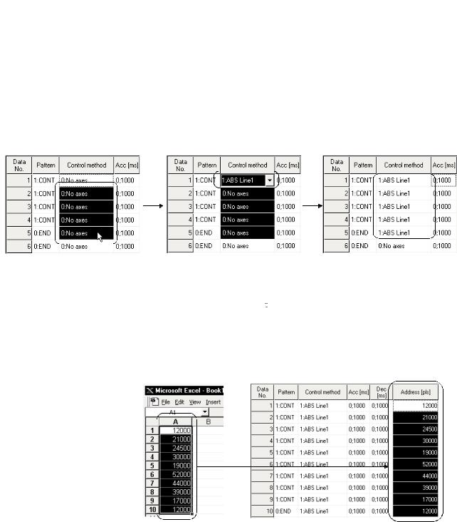
(1)Outstanding operability
1)Positioning data and start block data can be cut, copied and pasted efficiently.
[Useful drag range batch setting operation example]
Drag the batch setting range! |
Typing "1" sets "1: ABS Line 1" in the top cell! |
Pressing the Enter key batch-sets "1: |
|
|
ABS Line 1" in all cells in the dragged |
|
|
range! |
2) Data created with MicrosoftR Excel or Word can be copied and utilized as positioning data.
[Example of utilizing Excel data as positioning data]
Excel worksheet |
Positioning setting screen |
Copy the address data |
Choose and paste the |
created with Excel ! |
utilized data No. column! |
1 - 2 |
1 - 2 |
1. OVERVIEW |
MELSOFT |
|
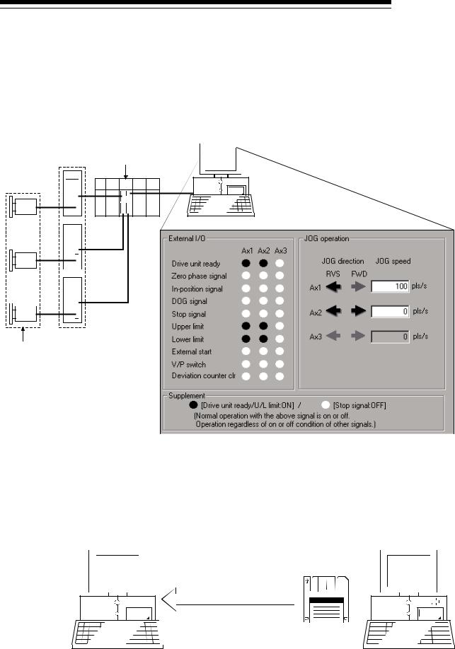
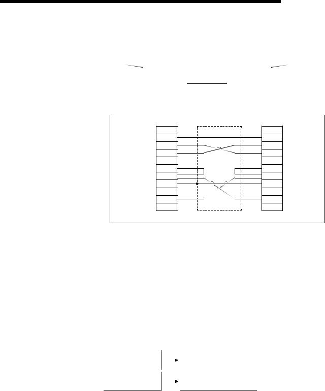
(3) Checking connect of general-purpose servo system
In a general-purpose servo system which uses the AD75P(S3) positioning module, the checking connect function of GX Configurator-AP allows the AD75P(S3) to be initialized, I/O signals to/from external devices to be monitored, and JOG operation to be performed.
The connection of the positioning system can be checked by monitoring signals from the external devices, and the rotation directions of servomotors can be checked by performing JOG operation.
Servo amplifiers AD75P
External devices such as servomotors and limit switches
(4) Utilization of SW1RX/IVD/NX-AD75P data
Since the data created with type SW1RX/IVD/NX-AD75P positioning module software package can be utilized on GX Configurator-AP, valuable resources can be used efficiently.
GX Configurator-AP may also be saved as SW1RX/IVD/NX-AD75P format data.
[Data utilization example]
GX Configurator-AP SW1IVD-AD75P
Open other format file.
Existing data created with SW1IVD-AD75P
1 - 3 |
1 - 3 |
1. OVERVIEW |
MELSOFT |
|
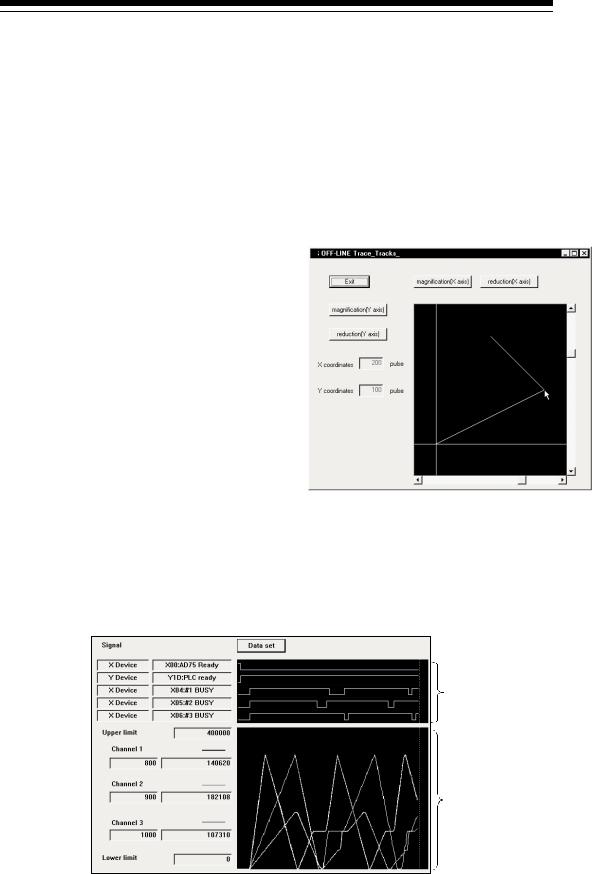
(5) Enhanced functions assist debugging and maintenance
Functions have been enhanced the offline simulation function displays a virtual positioning result which has been calculated from the addresses and command speeds set in positioning data and the monitor function is useful for debugging and maintenance of the positioning system, e.g. sampling monitor which shows the positioning module's I/O signal, external I/O signal and buffer memory states with a line graph.
[Offline simulation example]
This example assumes that the following positioning data was offline simulated.
Positioning data #1
Data |
Pattern |
Control |
Address |
Command |
|
No. |
Method |
Speed |
|||
|
|
||||
1 |
CONT |
ABS |
200 |
150,000 |
|
Line 2 |
pls/s |
||||
|
|
|
|||
2 |
END |
ABS |
100 |
150,000 |
|
Line 2 |
pls/s |
||||
|
|
|
Positioning data #2
Data |
Pattern |
Control |
Address |
Command |
|
No. |
Method |
Speed |
|||
|
|
||||
1 |
- |
- |
100 |
- |
|
2 |
- |
- |
200 |
- |
2-axis interpolation simulation screen
Locus data is displayed for 2-axis interpolation control. Waveform data of speed is displayed for 1-axis control. When positioning data is set, offline simulation allows you to pre-assume axis operation in advance, reducing debugging time.
[Sampling monitor example]
Out of AD75's I/O signals, external I/O signals and status signals, up to 5 points can be monitored.
In a line graph, up to 3 points can be monitored from buffer memory.
1 - 4 |
1 - 4 |

1. OVERVIEW |
MELSOFT |
|
|
(6) Real-time checking of error and warning factors |
|
With the online help function, you can instantaneously check the occurrence |
|
factor and corrective action of the error or warning code displayed on the |
|
operation monitor, error history monitor or other screen of the positioning system. |
<Online help function> |
<Operation monitor> |
Error occurrence!
(7) Simultaneous start of GX Configurator-AP and GX Developer
GX Configurator-AP can be started simultaneously with the GX Developer. (Two COM ports are required to make communication with the programmable controller CPU and positioning module at the same time.)
[Example of starting GX Configurator-AP and GX Developer simultaneously]
1 - 5 |
1 - 5 |
1. OVERVIEW |
MELSOFT |
|
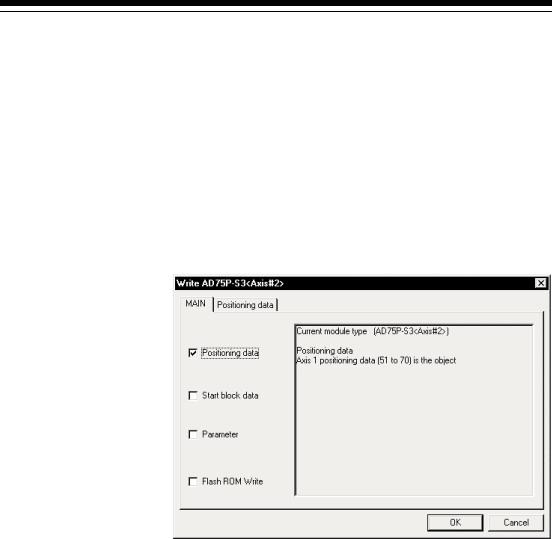
(8) Read from AD75/write to AD75/verify AD75 data can be performed axis-by-axis on a data basis
GX Configurator-AP allows each of the positioning data, start block data and parameters to be specified as the object of read from AD75/write to AD75/verify AD75 data axis-by-axis.
Further, positioning data can be specified on a data No. basis, and block No. 0 of start block data can be specified independently.
Hence, during debugging when data is written frequently for modification, wasteful waiting time is greatly reduced to improve working efficiency.
[Write range is set to 2-axis positioning data No. 51 to 70]
1 - 6 |
1 - 6 |
1. OVERVIEW |
MELSOFT |
|
1.2 Manual Makeup
This manual is made up of 12 chapters and appendices.
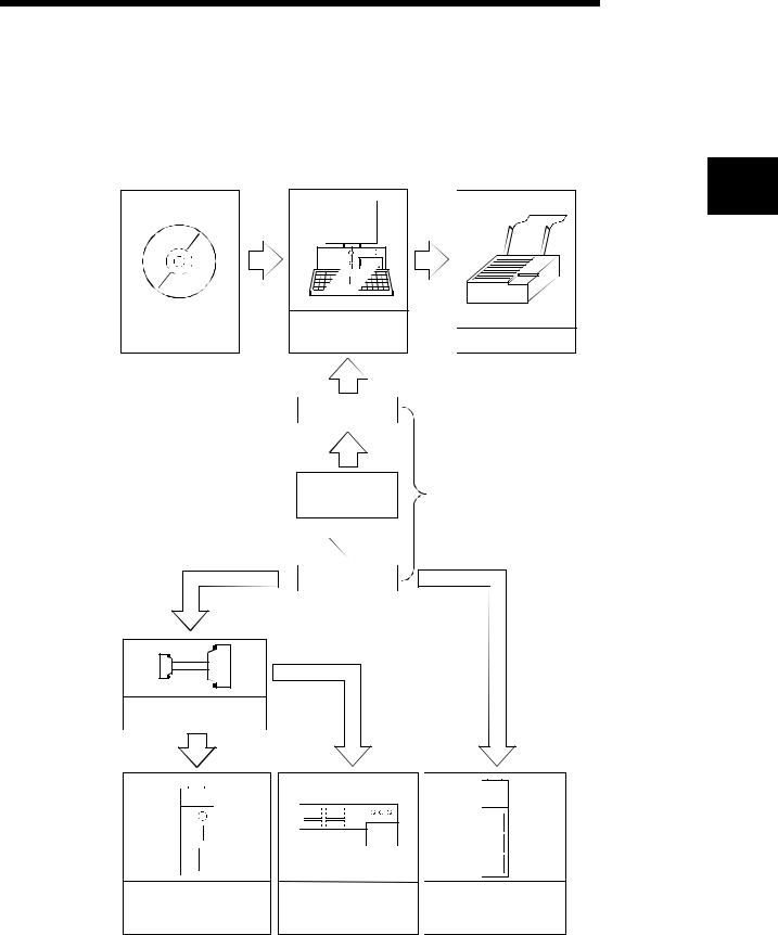
This manual assumes that GX Configurator-AP is used to perform steps from positioning system connection checking to operation in the following procedure.
<Sequence of steps taken by the user up to positioning system operation>
Step 1: Install and wire the positioning system. |
Refer To |
• Install and wire the programmable controller (such as the programmable controller CPU, |
|
positioning module and I/O modules), servo amplifiers, motors, external switches and other |
AD75 User's Manual |
external devices. |
|
Step 2: Check the GX Configurator-AP functions and learn the basic operation. |
Refer To |
• Check the system with which GX Configurator-AP can be used. |
Chapter 2 |
• Check the functions that can be performed by GX Configurator-AP. |
Chapter 3 |
• Install GX Configurator-AP in the peripheral device and start the program. |
Chapter 4 |
• Learn the GX Configurator-AP screen makeup and basic operation. |
Chapter 5 |
Step 3: Start operation of GX Configurator-AP. |
Refer To |
• Create a project which will be the object of operation performed on GX Configurator-AP. |
Chapter 6 |
Step 4: Check the connection and initial operation of the positioning system. |
Refer To |
|
• Check the version of the positioning module. |
|
|
• Check connection according to the signal states from the external devices.. |
|
|
• Check the alarm or warning of the positioning module. |
|
|
• Check the alarm or warning of the servo amplifiers (AD75M only) |
|
|
• Check that the initial settings are the same on the peripheral device and servo amplifiers. |
Chapter 7 |
|
(AD75M only) |
||
|
||
• Check that the servomotors are run by JOG operation. |
|
|
• Check that the upper/lower limit, DOG and zero point signals turned on/off by JOG operation. |
|
|
(AD75M only) |
|
|
• Check that the servomotor speed does not exceed the maximum speed. (AD75M only) |
|
(To the next page)
1 - 7 |
1 - 7 |
1. OVERVIEW |
|
MELSOFT |
|
|
|
|
(From the preceding page) |
|
Step 5: Set and write data to the positioning module. |
Refer To |
• Set the parameters appropriate for the positioning system and control. |
|
• Set the servo parameters appropriate for the specifications of the servo amplifiers and motors |
Chapter 8 |
used. |
|
•Set the positioning data.
•Check the parameter, positioning data and start block data settings on the error check screen.
• Check the positioning data on the offline simulation (virtual positioning) screen. |
Chapter 9 |
•Make the corresponding setting if start block data, condition data, indirect data or M code comment is required.
• Write the set data to the positioning module. |
Chapter 10 |
Step 6: Perform test operation and check and adjust the settings. |
Refer To |
|
• Check positioning control and test on the monitor screen. |
|
|
• Specify the positioning data and perform test operation. |
|
|
• Specify the start block data and perform test operation. |
|
|
• Make software limit test and error compensation by current value change, JOG operation or |
|
|
manual pulse generator operation. |
Chapter 11 |
|
• Perform original position return test. |
||
|
||
• Perform speed change test to find proper speed. |
|
|
• If motor torque is not proper, perform torque control test to change the setting. |
|
|
• Check undershoot, settling time and oscillation width in the test of position control gain 1 of servo |
|
|
parameters. (AD75M only) |
|
Step 7: Positioning system operation. |
Refer To |
• Operate the positioning system with the programmable controller CPU program. |
AD75 User's Manual |
1 - 8 |
1 - 8 |
2. SYSTEM CONFIGURATION
2. SYSTEM CONFIGURATION
2.1System Configuration
(1)Overall configuration of this system
|
Peripheral device |
|
|
GX Configurator-AP |
(Refer to Section 2.2) |
RS-232 cable
RS-232/RS-422 |
Refer to (2) |
|||||
converter |
||||||
|
||||||
|
|
|
|
|
|
|
|
|
|
|
|
|
|
RS-422 cable
Conversion cable (A1SD75-C01HA)
MELSOFT
2
AD75P1/P2/P3
AD75P1-S3/P2-S3/P3-S3
AD75M1/M2/M3
2 - 1 |
2 - 1 |
2. SYSTEM CONFIGURATION |
MELSOFT |
|
(2) About the RS-232 cable
For use of the FX-232AW(C) (Mitsubishi Electric make)
|
|
|
|
|
|
|
RS-232 |
RS-422 |
|||||
|
|
Peripheral |
|
|
|
|
FX-232AW(C) |
|
|
|
|
AD75 side |
|
|
|
|
|
|
|
|
|
|
|
||||
|
|
|
|
|
|
|
|
||||||
|
|
device side |
|
|
|
|
|
|
|
|
|||
|
|
|
|
|
|
|
|
|
|
|
|
||
2 |
|
|
|
|
|
|
|
|
|
|
|
|
|
|
|
|
|
|
|
|
|
|
|
||||
|
|
RS-232 cable wiring |
|
|
|
|
|
||||||
|
|
|
|
|
|
|
|||||||
|
|
|
|
|
|
|
|
||||||
|
|
|
|
|
|
Peripheral device side |
Converter side |
||||||
|
Pin No. |
Pin No. |
|
FG |
1 |
1 |
FG |
TXD |
2 |
2 |
TXD |
RXD |
3 |
3 |
RXD |
RTS |
4 |
4 |
RTS |
CTS |
5 |
5 |
CTS |
DSR |
6 |
6 |
DSR |
SG |
7 |
7 |
SG |
DTR |
20 |
20 |
DTR |
|
|
Shield |
|
The following products of RS-232 and RS-422 cables are recommended.
Cable |
Maker |
FX-232AW(C) (RS-232/RS-422 converter) |
|
F2-232CAB*1 (when peripheral device has D-sub 25-pin connector) |
|
F2-232CAB-1*1 (when peripheral device has D-sub 9-pin connector) |
Mitsubishi |
FX-422CAB (0.3m) |
Electric |
FX-422CAB-150 (1.5m) |
|
AC30N2A (when peripheral device has D-sub 25-pin connector) |
|
*1: To identify compatible products, check the type indicated on the cable's type label.
Incompatible product |
|
Compatible product (with F/FX/A) |
F2-232CAB |
|
F2-232CAB(F/FX/A) |
Y990C***** |
|
Y990C***** |
F2-232CAB-1 |
|
F2-232CAB-1(F/FX/A) |
Y990C***** |
|
Y990C***** |
2 - 2 |
2 - 2 |
2. SYSTEM CONFIGURATION |
MELSOFT |
|
•Before handling the RS-422 interface conversion cable/converter, please read its specifications, precautions, etc. carefully in the manual of the corresponding product and handle it correctly.
•When disconnecting or reconnecting the conversion cable/converter that receives 5VDC power from the RS-422 interface, switch power off on the programmable controller side before starting work.
•When disconnecting or reconnecting the peripheral device or conversion cable that does not receive 5VDC power from the RS-422 interface (whose power is supplied from an external power supply), be sure to use an earth band or touch a grounded metal object, etc. before starting work to discharge static electricity from the cable, human body, etc. After that, handle it in the following procedure.
1)Switch power off on the personal computer side.
2)Power off the conversion cable/converter. When it has an FG terminal, ground it.
3)Connect/disconnect the conversion cable/converter between the personal computer and programmable controller CPU.
4)Power on the conversion cable/converter.
5)Power on the personal computer.
6)Start up GX Configurator-AP
2 - 3 |
2 - 3 |

2. SYSTEM CONFIGURATION |
MELSOFT |
|
2.2 Operating Environment
The operating environment of GX Configurator-AP is indicated below.
|
Item |
|
|
|
Description |
Peripheral device |
Personal computer on which Windows R operates. |
||||
Computer main unit |
Refer to the following table "Used operating system and performance required for |
||||
|
CPU |
||||
|
personal computer". |
|
|
||
|
Required memory |
|
|
||
|
|
|
|
|
|
Hard disk free space |
10MB or more 1 |
|
|
||
Disk drive |
CD-ROM disk drive |
|
|
||
Display |
800 × 600 dot or more resolution 2 |
||||
|
|
Microsoft R |
Windows R |
95 Operating System |
|
|
|
Microsoft R |
Windows R |
98 Operating System |
|
|
|
Microsoft R |
Windows R |
Millennium Edition Operating System |
|
|
|
Microsoft R |
Windows NTR Workstation Operating System Version 4.0 |
||
|
|
Microsoft R |
Windows R |
2000 Professional Operating System |
|
Operating system |
Microsoft R |
Windows R |
XP Professional Operating System |
||
Microsoft R |
Windows R |
XP Home Edition Operating System |
|||
|
|
Microsoft R |
Windows Vista R |
Home Basic Operating System |
|
|
|
Microsoft R |
Windows Vista R |
Home Premium Operating System |
|
|
|
Microsoft R |
Windows Vista R |
Business Operating System |
|
|
|
Microsoft R |
Windows Vista R |
Ultimate Operating System |
|
|
|
Microsoft R |
Windows Vista R |
Enterprise Operating System |
|
 1: At minimum, free space of 15GB is required for Windows Vista R .
 2: Resolution 1024 × 768 pixels or higher is recommended for Windows Vista R .
Used operating system and performance required for personal computer
|
|
Operating system |
Performance Required for Personal Computer |
||
|
|
|
CPU |
Required memory |
|
|
|
|
|
||
Windows R |
95 (Service Pack 1 or more) |
PentiumR |
133MHz or more |
32MB or more |
|
Windows R |
98 |
|
PentiumR |
133MHz or more |
32MB or more |
Windows R |
Me |
|
PentiumR |
150MHz or more |
32MB or more |
Windows NTR Workstation 4.0 (Service Pack 3 or more) |
PentiumR |
133MHz or more |
32MB or more |
||
Windows R |
2000 Professional |
PentiumR |
133MHz or more |
64MB or more |
|
Windows R |
XP Professional |
PentiumR |
300MHz or more |
128MB or more |
|
Windows R |
XP Home Edition |
PentiumR |
300MHz or more |
128MB or more |
|
Windows Vista R |
Home Basic |
PentiumR |
1GHz or more |
1GB or more |
|
Windows Vista R |
Home Premium |
Pentium R |
1GHz or more |
1GB or more |
|
Windows Vista R |
Business |
PentiumR |
1GHz or more |
1GB or more |
|
Windows Vista R |
Ultimate |
PentiumR |
1GHz or more |
1GB or more |
|
Windows Vista R |
Enterprise |
PentiumR |
1GHz or more |
1GB or more |
|
2 - 4 |
2 - 4 |
2. SYSTEM CONFIGURATION |
MELSOFT |
|
The functions shown below are not available for Windows R XP and Windows Vista R .
If any of the following functions is attempted, this product may not operate normally.
Start of application in Windows R compatible mode
Fast user switching
Remote desktop
Large fonts (Details setting of Display Properties)
Also, 64-bit version WindowsR XP and Windows VistaR are not supported.
Use a USER authorization or higher in Windows Vista R .
2 - 5 |
2 - 5 |

3. FUNCTION LIST |
MELSOFT |
|
3. FUNCTION LIST
3.1 Function List
(1) Function list
GX Configurator-AP functions are listed below mode-by-mode.
|
|
Mode |
Main Screen |
Function |
Description |
|
|
|
|
|
Set the basic parameters1, basic parameters2, extended |
|
|
|
Parameter |
Parameter setting |
parameters1, extended parameters2, OPR basic parameters and |
|
|
|
|||
3 |
|
|
|
|
OPR extended parameters on an axis basis. |
|
|
Servo parameter |
Servo parameter |
Set the servo basic parameters, servo adjustment parameters and |
|
|
|
|
|||
|
|
|
(AD75M only) |
setting |
servo extension parameters on an axis basis. |
|
|
|
|||
|
|
|
|
Positioning data |
Set the positioning data, such as pattern, control method, |
|
|
|
|
setting |
accel/decel time and address, on an axis basis. |
|
|
|
|
Positioning data |
Monitor the positioning data during execution on an axis basis. |
|
|
|
Positioning data |
monitor |
|
|
|
|
|
||
|
|
|
axis #1 |
Positioning data test |
Perform test operation of positioning control on an axis or |
|
|
|
Positioning data |
positioning data basis. |
|
|
|
|
|
||
|
|
|
axis #2 |
Teaching |
Set the feed address of the moved axis to the address of |
|
|
|
Positioning data |
positioning data by JOG operation or the like. |
|
|
|
|
|
||
|
|
Edit |
axis #3 |
M code comment |
Set comments to the M codes assigned to the positioning data on |
|
|
|
|
setting |
an axis basis. |
|
|
|
|
Offline simulation |
Assume axis operation from the set positioning data on an axis |
|
|
|
|
basis. |
|
|
|
|
|
|
|
|
|
|
|
Start block data |
Set the starting mode, etc. of the positioning data specified for |
|
|
|
|
setting |
points on an axis basis. |
|
|
|
Start block axis |
Start block data |
Monitor the point at which positioning control is being executed on |
|
|
|
#1 |
monitor |
an axis basis. |
|
|
|
Start block axis |
Start block data test |
Perform test operation of positioning control from the point of the |
|
|
|
#2 |
specified block on an axis basis. |
|
|
|
|
|
||
|
|
|
Start block axis |
Condition data |
Set the data which is used as the starting condition of the start |
|
|
|
#3 |
setting |
block data on an axis basis. |
|
|
|
|
Indirect data setting |
Set the positioning data numbers set to the indirect designating |
|
|
|
|
buffer memory of the AD75 on an axis basis. |
|
|
|
|
|
|
|
|
|
|
|
Operation monitor |
Monitor the operating states, such as addresses, axis speeds, axis |
|
|
|
|
(main screen) |
statuses and executed positioning data numbers, of all axes. |
|
|
|
|
History monitor |
Monitor the error, warning, start or error-time start history of all |
|
|
|
|
axes. |
|
|
|
|
|
|
|
|
|
|
|
Signal monitor |
Monitor the X/Y devices, external signals or status signals of all |
|
|
|
Operation |
axes. |
|
|
|
Monitor |
|
||
|
|
monitor (test) |
Operation monitor |
Monitor the control states, AD75 parameter settings or others of all |
|
|
|
|
|||
|
|
|
|
(dialog) |
axes. |
|
|
|
|
Servo monitor |
Monitor the servo amplifier and servomotor states of all axes. |
|
|
|
|
|
Test the positioning data number-specified start, current value |
|
|
|
|
Operation test |
change, speed change, original position return, JOG operation and |
|
|
|
|
|
manual pulse generator operation of all axes. |
3 - 1 |
3 - 1 |

|
3. FUNCTION LIST |
|
|
MELSOFT |
|
||
|
|
|
|
|
|
||
|
|
|
|
|
|
||
|
|
|
|
|
|
|
|
|
Mode |
Main Screen |
Function |
Description |
|
|
|
Monitor |
Sampling |
Sampling monitor |
Monitor the specified signals and buffer memory data while |
|
|
||
monitor |
simultaneously sampling them. |
|
|
||||
|
|
|
|
|
|||
|
|
AD75P checking |
AD75P checking |
Display signals from external devices. Also test initial operation by |
|
|
|
|
|
connect |
|
|
|||
|
|
connect |
JOG operation. |
|
|
||
|
|
(AD75P only) |
|
|
|||
|
|
|
|
|
|
|
|
|
|
|
Initial check |
Monitor the error/warning history of the AD75M or servo amplifiers. |
|
|
|
|
|
|
Module name |
Compare the servo parameters read from the servo amplifiers to |
|
|
|
|
|
AD75M servo |
check |
the AD75M with the servo parameters on the peripheral device. |
|
|
|
Diagnosis |
starting up |
Upper/lower limit |
Judge the upper and lower limit switch operations by JOG |
|
3 |
||
|
|
(AD75M only) |
check |
operation. |
|
||
|
|
|
RPM check |
Display the motor speeds for JOG operation and the motor speeds |
|
|
|
|
|
|
|
|
|||
|
|
|
set to the servo basic parameters. |
|
|
||
|
|
|
|
|
|
||
|
|
AD75M position |
AD75M position |
Adjust the servomotor characteristics such as response level and |
|
|
|
|
|
control gain |
|
|
|||
|
|
control gain |
settling time. |
|
|
||
|
|
(AD75M only) |
|
|
|||
|
|
|
|
|
|
|
|
|
|
|
|
Trace the specified data (position instruction, servomotor speed, |
|
|
|
|
|
Wavy display |
Wavy display |
etc.) for a given time and display the waveform data relative to the |
|
|
|
Trace*1 |
|
|
time axis. |
|
|
||
|
|
Tracks displays |
Tracks displays |
Trace the position command or real value for a given time and |
|
|
|
|
|
display the track data of the axes. |
|
|
|||
|
|
|
|
|
|
||
*1 The following positioning modules do not have the trace mode.
•AD75P1/P2/P3
•A1SD75P1/P2/P3
3 - 2 |
3 - 2 |

3. FUNCTION LIST |
MELSOFT |
|
(2) Menu list
The menu bar drop-down menus are listed below.
Project |
|
|
|
New Project |
|||
|
|
|
|||||
|
|
|
|
Open Project |
|||
|
|
|
|
||||
|
|
|
|
Save Project |
|||
|
|
|
|
||||
|
|
|
|
Save as Project |
|||
|
|
|
|
||||
|
|
|
|
Delete Product |
|||
|
|
|
|
||||
|
|
|
|
Verify Project |
|||
|
|
|
|
||||
|
|
|
|
Import file |
|||
|
|
|
|
||||
|
|
|
|
|
|
|
File reading of SW1RX/IVD/NX-AD75P |
|
|
|
|
|
|
|
|
|
|
|
|
|
|
|
|
|
|
|
|
|
|
|
File reading of CSV form positioning data |
|
|
|
|
|
|
|
|
|
|
|
|
|
|
|
File reading of trace data |
|
|
|
|
|
|
|
|
|
|
|
|
Export file |
|||
|
|
|
|
||||
|
|
|
|
|
|
|
File writing of SW1RX/IVD/NX-AD75P |
|
|
|
|
|
|
|
|
|
|
|
|
|
|
|
|
|
|
|
|
|
|
|
File writing of CSV form positioning data |
|
|
|
|
|
|
|
|
|
|
|
|
|
|
|
File writing of trace data |
|
|
|
|
|
|
|
|
|
|
|
|
Change AD75 model |
|||
|
|
|
|
||||
|
|
|
|
||||
|
|
|
|
||||
|
|
|
|
Printer setup |
|||
|
|
|
|
||||
|
|
|
|
Latest file |
|||
|
|
|
|
||||
|
|
|
|
Exit |
|||
|
|
|
|
||||
Edit |
|
|
|
Cut |
|||
|
|
||||||
|
|
|
|
Copy |
|||
|
|
|
|||||
|
|
|
|
Paste |
|||
|
|
|
|||||
|
|
|
|
Select all |
|||
|
|
|
|||||
|
|
|
|
Jump |
|||
|
|
|
|||||
|
|
|
|
Clear row |
|||
|
|
|
|||||
|
|
|
|
Clear column |
|||
|
|
|
|||||
|
|
|
|
Axis copy |
|||
|
|
|
|||||
|
|
|
|
Start block copy |
|||
|
|
|
|||||
|
|
|
|
Positioning data input |
|||
|
|
|
|||||
|
|
|
|
Start block data input |
|||
|
|
|
|||||
|
|
|
|
Parameter data input |
|||
|
|
|
|||||
|
|
|
|
Servo parameter |
|||
|
|
|
|||||
|
|
|
|
M code comment |
|||
|
|
|
|||||
|
|
|
|
Condition data edit |
|||
|
|
|
|||||
|
|
|
|
Indirect data edit |
|||
|
|
|
|||||
|
|
|
|
Offline simulator |
|||
|
|
|
|||||
View |
|
|
|
Toolbar |
|||
|
|
|
|||||
|
|
|
|
|
|
|
Project toolbar |
|
|
|
|
|
|
||
|
|
|
|
|
|
|
Edit toolbar |
|
|
|
|
|
|
||
|
|
|
|
|
|
|
Online toolbar |
|
|
|
|
|
|
||
|
|
|
|
Status bar |
|||
|
|
|
|
||||
|
|
|
|
Change menu |
|||
|
|
|
|
||||
|
|
|
|
Move upward |
|||
|
|
|
|
||||
|
|
|
|
Select Axis |
|||
|
|
|
|
||||
|
|
|
|
|
|
|
Axis #1 |
|
|
|
|
|
|
|
|
|
|
|
|
|
|
||
|
|
|
|
|
|
|
Axis #2 |
|
|
|
|
|
|
||
|
|
|
|
|
|
|
Axis #3 |
|
|
|
|
|
|
||
|
|
|
|
Select start block |
|||
|
|
|
|
||||
|
|
|
|
Edit property dialog |
|||
|
|
|
|
||||
|
|
|
|
Large Icons |
|||
|
|
|
|
||||
|
|
|
|
Small Icons |
|||
|
|
|
|
||||
|
|
|
|
List view |
|||
|
|
|
|
||||
|
|
|
|
Detailed view |
|||
|
|
|
|
||||
Online |
|
|
|
|
Read from AD75 |
|||||
|
|
|
||||||||
|
|
|
|
|
Write to AD75 |
|||||
|
|
|
|
|||||||
|
|
|
|
|
Verify AD75 data |
|||||
|
|
|
|
|||||||
|
|
|
|
OS information |
||||||
|
|
|
|
|||||||
|
|
|
|
Flash-ROM request |
||||||
|
|
|
|
|||||||
|
|
|
|
Initialize AD75 |
||||||
|
|
|
|
|||||||
|
|
|
|
Monitor |
||||||
|
|
|
|
|||||||
|
|
|
|
|
|
|
|
Monitor start |
||
|
|
|
|
|
|
|
||||
|
|
|
|
|
|
|
|
History monitor |
||
|
|
|
|
|
|
|
||||
|
|
|
|
|
|
|
|
Signal monitor |
||
|
|
|
|
|
|
|
||||
|
|
|
|
|
|
|
|
Operation monitor |
||
|
|
|
|
|
|
|
||||
|
|
|
|
|
|
|
|
Servo monitor |
||
|
|
|
|
|
|
|
||||
|
|
|
|
Test |
||||||
|
|
|
|
|||||||
|
|
|
|
|
|
|
|
Test start |
||
|
|
|
|
|
|
|
||||
|
|
|
|
|
|
|
|
Start condition |
||
|
|
|
|
|
|
|
||||
|
|
|
|
|
|
|
|
Operation Test |
||
|
|
|
|
|
|
|
||||
|
|
|
|
|
|
|
|
Teaching |
||
|
|
|
|
|
|
|
|
|||
|
|
|
|
|
|
|
|
All axis On/Off |
||
|
|
|
|
|
|
|
||||
|
|
|
|
|
|
|
|
Designate Off |
||
|
|
|
|
|
|
|
||||
|
|
|
|
|
|
|
|
|
|
Designate #1 Off |
|
|
|
|
|
|
|
|
|
|
|
|
|
|
|
|
|
|
|
|
|
Designate #2 Off |
|
|
|
|
|
|
|
|
|
|
|
|
|
|
|
|
|
|
|
|
|
Designate #3 Off |
|
|
|
|
|
|
|
|
|
|
|
|
|
|
|
Error Reset |
||||||
|
|
|
|
|||||||
|
|
|
|
|
|
|
|
Error Reset #1 |
||
|
|
|
|
|
|
|
|
|||
|
|
|
|
|
|
|
|
Error Reset #2 |
||
|
|
|
|
|
|
|
|
|||
|
|
|
|
|
|
|
|
Error Reset #3 |
||
|
|
|
|
|
|
|
|
|||
|
|
|
|
M code Off |
||||||
|
|
|
|
|||||||
|
|
|
|
|
|
|
|
M code #1 Off |
||
|
|
|
|
|
|
|
|
|||
|
|
|
|
|
|
|
|
M code #2 Off |
||
|
|
|
|
|
|
|
|
|||
|
|
|
|
|
|
|
|
M code #3 Off |
||
|
|
|
|
|
|
|
|
|||
Tool |
|
|
|
Initialize data |
||||||
|
|
|||||||||
|
|
|
|
|
Initialize parameter |
|||||
|
|
|
|
|||||||
|
|
|
|
|
Initialize servo parameter |
|||||
|
|
|
|
|||||||
|
|
|
|
|
Register servo name |
|||||
|
|
|
|
|||||||
|
|
|
|
|
Error check |
|||||
|
|
|
|
|||||||
|
|
|
|
|
Option |
|||||
|
|
|
|
|||||||
Help |
|
|
|
Error/Warning Help |
||||||
|
|
|
||||||||
|
|
|
|
|
List of Buffer memory |
|||||
|
|
|
|
|
||||||
|
|
|
|
|
About |
|||||
|
|
|
|
|
||||||
|
|
|
|
|
Connection to MELFANSweb |
|||||
|
|
|
|
|
||||||
3 - 3 |
3 - 3 |
Loading...