


 Loading...
MOTION CONTROLLER
User’s Manual
type A173UHCPU,A172SHCPUN, A171SHCPUN
MITSUBISHI  ELECTRIC

INTORODUCTION
Thank you for purchasing the Mitsubishi Motion Controller/A173UHCPU/A172SHCPUN/A171SHCPUN. This instruction manual describes the handing and precautions of this unit. Incorrect handing will lead to unforeseen events, so we ask that you please read this manual thoroughly and use the unit correctly.
Please make sure that this manual is delivered to the final user of the unit and that it is stored for future reference.
Precautions for Safety
Please read this instruction manual and enclosed documents before starting installation, operation, maintenance or inspections to ensure correct usage. Thoroughly understand the machine, safety information and precautions before starting operation.
The safety precautions are ranked as "Warning" and "Caution" in this instruction manual.
 WARNING
 CAUTION
When a dangerous situation may occur if handling is mistaken leading to fatal or major injuries.
When a dangerous situation may occur if handling is mistaken leading to medium or minor injuries, or physical damage.
Note that some items described as cautions may lead to major results depending on the situation. In any case, important information that must be observed is described.
− I −
For Sate Operations
1. Prevention of electric shocks
 WARNING
Never open the front case or terminal covers while the power is ON or the unit is running, as this may lead to electric shocks.
Never run the unit with the front case or terminal cover removed. The high voltage terminal and charged sections will be exposed and may lead to electric shocks.
Never open the front case or terminal cover at times other than wiring work or periodic inspections even if the power is OFF. The insides of the control unit and servo amplifier are charged and may lead to electric shocks.
When performing wiring work or inspections, turn the power OFF, wait at least ten minutes, and then check the voltage with a tester, etc. Failing to do so may lead to electric shocks.
Always ground the control unit, servo amplifier and servomotor with Class 3 grounding. Do not ground commonly with other devices.
The wiring work and inspections must be done by a qualified technician.
Wire the units after installing the control unit, servo amplifier and servomotor. Failing to do so may lead to electric shocks or damage.
Never operate the switches with wet hands, as this may lead to electric shocks.
Do not damage, apply excessive stress, place heavy things on or sandwich the cables, as this may lead to electric shocks.
Do not touch the control unit, servo amplifier or servomotor terminal blocks while the power is ON, as this may lead to electric shocks.
Do not touch the internal power supply, internal grounding or signal wires of the control unit and servo amplifier, as this may lead to electric shocks.
2. For fire prevention
 CAUTION
Install the control unit, servo amplifier, servomotor and regenerative resistor on inflammable material. Direct installation on flammable material or near flammable material may lead to fires.
If a fault occurs in the control unit or servo amplifier, shut the power OFF at the servo amplifier’s power source. If a large current continues to flow, fires may occur.
When using a regenerative resistor, shut the power OFF with an error signal. The regenerative resistor may abnormally overheat due to a fault in the regenerative transistor, etc., and may lead to fires.
Always take heat measures such as flame proofing for the inside of the control panel where the servo amplifier or regenerative resistor is installed and for the wires used. Failing to do so may lead to fires.
− II −
3. For injury prevention
 CAUTION
Do not apply a voltage other than that specified in the instruction manual on any terminal. Doing so may lead to destruction or damage.
Do not mistake the terminal connections, as this may lead to destruction or damage. Do not mistake the polarity (+/-), as this may lead to destruction or damage.
The servo amplifier's heat radiating fins, regenerative resistor and servo amplifier, etc., will be hot while the power is ON and for a short time after the power is turned OFF. Do not touch these parts as doing so may lead to burns.
Always turn the power OFF before touching the servomotor shaft or coupled machines, as these parts may lead to injuries.
Do not go near the machine during test operations or during operations such as teaching. Doing so may lead to injuries.
4. Various precautions
Strictly observe the following precautions.
Mistaken handling of the unit may lead to faults, injuries or electric shocks.
(1) System structure
 CAUTION
Always install a leakage breaker on the control unit and servo amplifier power source.
If installation of a magnetic contactor for power shut off during an error, etc., is specified in the instruction manual for the servo amplifier, etc., always install the magnetic contactor.
Install an external emergency stop circuit so that the operation can be stopped immediately and the power shut off.
Use the control unit, servo amplifier, servomotor and regenerative resistor with the combinations listed in the instruction manual. Other combinations may lead to fires or faults.
If safety standards (ex., robot safety rules, etc.,) apply to the system using the control unit, servo amplifier and servomotor, make sure that the safety standards are satisfied.
If the operation during a control unit or servo amplifier error and the safety direction operation of the control unit differ, construct a countermeasure circuit externally of the control unit and servo amplifier.
In systems where coasting of the servomotor will be a problem during emergency stop, servo OFF or when the power is shut OFF, use dynamic brakes.
Make sure that the system considers the coasting amount even when using dynamic brakes.
In systems where perpendicular shaft dropping may be a problem during emergency stop, servo OFF or when the power is shut OFF, use both dynamic brakes and magnetic brakes.
The dynamic brakes must be used only during emergency stop and errors where servo OFF occurs. These brakes must not be used for normal braking.
The brakes (magnetic brakes) assembled into the servomotor are for holding applications, and must not be used for normal braking.
Construct the system so that there is a mechanical allowance allowing stopping even if the stroke end limit switch is passed through at the max. speed.
Use wires and cables that have a wire diameter, heat resistance and bending resistance compatible with the system.
− III −
 CAUTION
Use wires and cables within the length of the range described in the instruction manual.
The ratings and characteristics of the system parts (other than control unit, servo amplifier, servomotor) must be compatible with the control unit, servo amplifier and servomotor.
Install a cover on the shaft so that the rotary parts of the servomotor are not touched during operation.
There may be some cases where holding by the magnetic brakes is not possible due to the life or mechanical structure (when the ball screw and servomotor are connected with a timing belt, etc.). Install a stopping device to ensure safety on the machine side.
(2) Parameter settings and programming
CAUTION
Set the parameter values to those that are compatible with the control unit, servo amplifier, servomotor and regenerative resistor model and the system application. The protective functions may not function if the settings are incorrect.
The regenerative resistor model and capacity parameters must be set to values that conform to the operation mode, servo amplifier and servo power unit. The protective functions may not function if the settings are incorrect.
Set the mechanical brake output and dynamic brake output validity parameters to values that are compatible with the system application. The protective functions may not function if the settings are incorrect.
Set the stroke limit input validity parameter to a value that is compatible with the system application. The protective functions may not function if the setting is incorrect.
Set the servomotor encoder type (increment, absolute position type, etc.) parameter to a value that is compatible with the system application. The protective functions may not function if the setting is incorrect.
Set the servomotor capacity and type (standard, low-inertia, flat, etc.) parameter to values that are compatible with the system application. The protective functions may not function if the settings are incorrect.
Set the servo amplifier capacity and type parameters to values that are compatible with the system application. The protective functions may not function if the settings are incorrect.
Use the program commands for the program with the conditions specified in the instruction manual.
Set the sequence function program capacity setting, device capacity, latch validity range, I/O assignment setting, and validity of continuous operation during error detection to values that are compatible with the system application. The protective functions may not function if the settings are incorrect.
Some devices used in the program have fixed applications, so use these with the conditions specified in the instruction manual.
The input devices and data registers assigned to the link will hold the data previous to when communication is terminated by an error, etc. Thus, an error correspondence interlock program specified in the instruction manual must be used.
Use the interlock program specified in the special function unit's instruction manual for the program corresponding to the special function unit.
− IV −
(3) Transportation and installation
 CAUTION
Transport the product with the correct method according to the weight.
Use the servomotor suspension bolts only for the transportation of the servomotor. Do not transport the servomotor with machine installed on it.
Do not stack products past the limit.
When transporting the control unit or servo amplifier, never hold the connected wires or cables.
When transporting the servomotor, never hold the cables, shaft or detector.
When transporting the control unit or servo amplifier, never hold the front case as it may fall off.
When transporting, installing or removing the control unit or servo amplifier, never hold the edges.
Install the unit according to the instruction manual in a place where the weight can be withstood. Do not get on or place heavy objects on the product.
Always observe the installation direction.
Keep the designated clearance between the control unit or servo amplifier and control panel inner surface or the control unit and servo amplifier, control unit or servo amplifier and other devices.
Do not install or operate control units, servo amplifiers or servomotors that are damaged or that have missing parts.
Do not block the intake/outtake ports of the servomotor with cooling fan.
Do not allow conductive matter such as screw or cutting chips or combustible matter such as oil enter the control unit, servo amplifier or servomotor.
The control unit, servo amplifier and servomotor are precision machines, so do not drop or apply strong impacts on them.
Securely fix the control unit and servo amplifier to the machine according to the instruction manual. If the fixing is insufficient, these may come off during operation.
Always install the servomotor with reduction gears in the designated direction. Failing to do so may lead to oil leaks.
Store and use the unit in the following environmental conditions.
|
Environment |
|
Conditions |
|
|
|
|
|
|
|
|
|
Control unit/servo amplifier |
|
Servomotor |
|
|
|
|
|
|
||
|
|
|
|
|
|
|
Ambient |
0° C to + 55° C |
|
0° C to + 40° C |
|
|
temperature |
(With no freezing) |
|
(With no freezing) |
|
|
Ambient humidity |
According to each instruction |
|
80% RH or less |
|
|
manual. |
|
(With no dew condensation) |
|
|
|
|
|
|
||
|
Storage |
According to each instruction |
|
− 20° C to + 65° C |
|
|
temperature |
manual. |
|
|
|
|
|
|
|
||
|
Atmosphere |
Indoors (where not subject to direct sunlight). |
|
||
|
No corrosive gases, flammable gases, oil mist or dust must exist |
|
|||
|
|
|
|||
|
Altitude |
1000m (3278.69ft.) or less above sea level |
|
||
|
|
|
|
||
|
Vibration |
According to each instruction manual |
|
||
|
|
|
|
|
|
|
|
|
|
|
|
− V −
 CAUTION
When coupling with the synchronization encoder or servomotor shaft end, do not apply impact such as by hitting with a hammer. Doing so may lead to detector damage.
Do not apply a load larger than the tolerable load onto the servomotor shaft. Doing so may lead to shaft breakage.
When not using the unit for a long time, disconnect the power line from the control unit or servo amplifier.
Place the control unit and servo amplifier in static electricity preventing vinyl bags and store. When storing for a long time, please consult our sales representative.
(4) Wiring
 CAUTION
Correctly and securely wire the wires. Reconfirm the connections for mistakes and the terminal screws for tightness after wiring. Failing to do so may lead to run away of the servomotor.
After wiring, install the protective covers such as the terminal covers to the original positions.
Do not install a phase advancing capacitor, surge absorber or radio noise filter (option FRBIF) on the output side of the servo amplifier.
Correctly connect the output side (terminals U, V, W). Incorrect connections will lead the servomotor to operate abnormally.
Do not connect a commercial power supply to the servomotor, as this may lead to trouble.
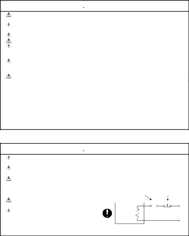
Do not mistake the direction of the surge absorbing diode installed on the DC relay for the control signal output of brake signals, etc. Incorrect installation may lead to signals not being output when trouble occurs or the protective functions not functioning.
Do not connect or disconnect the connection cables between each unit, the encoder cable or sequence expansion cable while the power is ON.
Servo amplifier
VIN |
|
(24VDC) |
|
Control output |
|
signal |
RA |
Securely tighten the cable connector fixing screws and fixing mechanisms. Insufficient fixing may lead to the cables combing off during operation.
Do not bundle the power line or cables.
(5) Trial operation and adjustment
 CAUTION
Confirm and adjust the program and each parameter before operation. Unpredictable movements may occur depending on the machine.
Extreme adjustments and changes may lead to unstable operation, so never make them.
When using the absolute position system function, on starting up, and when the controller or absolute value motor has been replaced, always perform a home position return.
− VI −
(6) Usage methods
 CAUTION
Immediately turn OFF the power if smoke, abnormal sounds or odors are emitted from the control unit, servo amplifier or servomotor.
Always execute a test operation before starting actual operations after the program or parameters have been changed or after maintenance and inspection.
The units must be disassembled and repaired by a qualified technician. Do not make any modifications to the unit.
Keep the effect or magnetic obstacles to a minimum by installing a noise filter or by using wire shields, etc. Magnetic obstacles may affect the electronic devices used near the control unit or servo amplifier.
When using the CE Mark-compliant equipment, refer to the "EMC Installation Guidelines" (data number IB(NA)-67339) for the motion controllers and refer to the corresponding EMC guideline information for the servo amplifiers, inverters and other equipment.
Use the units with the following conditions.
|
|
Conditions |
|
|||
Item |
A1S61PN |
A1S62PN |
CPU module's built- |
|||
|
in power supply |
|||||
|
|
|
|
|
|
|
Input power |
|
100 to 240VAC+10% |
|
|||
|
(85 to 264VAC)-15% |
|
||||
|
|
|
||||
Input frequency |
|
50/60Hz |
|
|
5% |
|
|
|
|
|
|||
|
|
|
|
|||
|
|
|
|
|||
Tolerable momentary |
|
Within 20ms |
|
|||
power failure |
|
|
||||
|
|
|
|
|
|
|
|
|
|
|
|
|
|
(7) Remedies for errors
 CAUTION
If an error occurs in the self diagnosis of the control unit or servo amplifier, confirm the check details according to the instruction manual, and restore the operation.
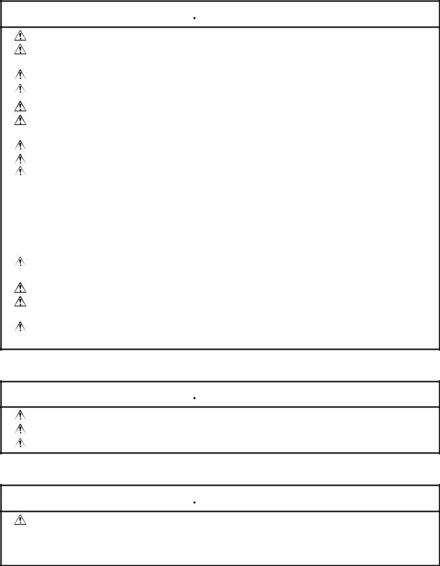
If a dangerous state is predicted in case of a power failure or product failure, use a servomotor with magnetic brakes or install a brake mechanism externally.
Use a double circuit construction so that the magnetic brake operation circuit can be operated by emergency stop signals set externally.
If an error occurs, remove the cause, secure the safety and then resume operation.
The unit may suddenly resume operation after a power failure is restored, so do not go near the machine. (Design the machine so that personal safety can be ensured even if the machine restarts suddenly.)
Shut off with servo ON signal OFF, alarm, magnetic brake signal.
Servo motor |
RA1 |
|
Magnetic brakes
Shut off with the emergency stop signal(EMG).
EMG
24VDC
− VII −
(8) Maintenance, inspection and part replacement
 CAUTION
Perform the daily and periodic inspections according to the instruction manual.
Perform maintenance and inspection after backing up the program and parameters for the control unit and servo amplifier.
Do not place fingers or hands in the clearance when opening or closing any opening. Periodically replace consumable parts such as batteries according to the instruction manual.
Do not touch the lead sections such as ICs or the connector contacts.
Do not place the control unit or servo amplifier on metal that may cause a power leakage or wood, plastic or vinyl that may cause static electricity buildup.
Do not perform a megger test (insulation resistance measurement) during inspection. When replacing the control unit or servo amplifier, always set the new unit settings correctly.
When the controller or absolute value motor has been replaced, carry out a home position return operation using one of the following methods, otherwise position displacement could occur.
1)After writing the servo data to the PC using peripheral device software, switch on the power again, then perform a home position return operation.
2)Using the backup function of the peripheral device software, load the data backed up before replacement.
After maintenance and inspections are completed, confirm that the position detection of the absolute position detector function is correct.
Do not short circuit, charge, overheat, incinerate or disassemble the batteries.
The electrolytic capacitor will generate gas during a fault, so do not place your face near the control unit or servo amplifier.
The electrolytic capacitor and fan will deteriorate. Periodically change these to prevent secondary damage from faults. Replacements can be made by our sales representative.
(9) Disposal
 CAUTION
Dispose of this unit as general industrial waste.
Do not disassemble the control unit, servo amplifier or servomotor parts.
Dispose of the battery according to local laws and regulations.
(10) General cautions
 CAUTION
All drawings provided in the instruction manual show the state with the covers and safety partitions removed to explain detailed sections. When operating the product, always return the covers and partitions to the designated positions, and operate according to the instruction manual.
− VIII −

Revisions
|
|
|
|
*The manual number is given on the bottom left of the back cover. |
||
|
|
|
|
|
|
|
Print Date |
*Manual Number |
|
|
|
|
Revision |
Apr.1998 |
IB(NA)-67395-B |
First edition |
||||
Sep.2000 |
IB(NA)-67395-C |
|
|
|
|
|
|
Addition |
|
|
|||
|
|
|
Addition of information on the A173UHCPU |
|||
|
|
|
|
|
|
|
|
|
|
Correction |
|
||
|
|
|
For Sate Operations (4. Various precautions (3), (6), (8)), CONTENTS, 1.1, |
|||
|
|
1.2.1, 1.2.2, 1.3, 1.4, 1.5.1, 1.5.2 (1), 1.5.3, 1.5.4, 1.5.5, 1.5.6, 2.1, 2.3, 2.3.1, |
||||
|
|
|
2.3.2 (2), 4.3, 4.4, 5.4.1, 5.4.1(3), 5.4.1 (4), 5.4.1 (5), APPENDICES |
|||
|
|
|
|
|
||
|
|
|
Delete |
|
||
|
|
1.5.7 (2), 5.3.1 (2) |
||||
|
|
|
|
|
|
|
This manual confers no industrial property rights or any rights of any other kind, nor does it confer any patent licenses. Mitsubishi Electric Corporation cannot be held responsible for any problems involving industrial property rights which may occur as a result of using the contents noted in this manual.
© 2000 Mitsubishi Electric Corporation
CONTENTS
1. SPECIFICATIONS OF MOTION SYSTEM COMPONENTS..................................................... |
1- 1 to 1-57 |
|
1.1 |
Overview of the Motion System ......................................................................................................... |
1- 1 |
1.2 |
Overall Configuration of Motion System ............................................................................................ |
1- 3 |
1.2.1 A172SHCPUN/A171SHCPUN System Overall Configuration .................................................... |
1- 3 |
|
1.2.2 A173UHCPU System Overall Configuration ............................................................................... |
1- 5 |
|
1.3 |
Equipment in System ......................................................................................................................... |
1- 7 |
1.4 |
General Specifications ...................................................................................................................... |
1-10 |
1.5 |
Specifications and Settings of Components ..................................................................................... |
1-11 |
1.5.1 A173UHCPU/A172SHCPUN/A171SHCPUN............................................................................. |
1-11 |
|
1.5.2 Extension Base Power Supply Module ...................................................................................... |
1-25 |
|
1.5.3 Base Units and Extension Cables.............................................................................................. |
1-28 |
|
1.5.4 Manual Pulse Generator/Synchronous Encoder Interface Module............................................ |
1-38 |
|
1.5.5 Teaching Unit ............................................................................................................................. |
1-49 |
|
1.5.6 SSCNET Cables and Termination Resistor and Their Connection Method .............................. |
1-53 |
|
1.5.7 Battery ........................................................................................................................................ |
1-57 |
|
2. DESIGN...................................................................................................................................... |
2- 1 to 2-22 |
|
2.1 |
System Designing Procedure ............................................................................................................ |
2- 1 |
2.2 |
System Design ................................................................................................................................... |
2- 4 |
2.3 |
External Circuit Design....................................................................................................................... |
2- 5 |
2.3.1 Power Supply Circuit Design...................................................................................................... |
2-10 |
|
2.3.2 Safety Circuit Design.................................................................................................................. |
2-12 |
|
2.3.3 Instructions for External Circuit Wiring Design........................................................................... |
2-16 |
|
2.4 |
Layout Design within Enclosure........................................................................................................ |
2-17 |
2.4.1 Location Environment................................................................................................................. |
2-17 |
|
2.4.2 Installing the Base Units............................................................................................................. |
2-18 |
|
2.4.3 Installation .................................................................................................................................. |
2-19 |
|
2.4.4 Calculating Heat Generated by A173UHCPU/A172SHCPUN/A171SHCPUN .......................... |
2-20 |
|
2.5 |
Design Checklist ............................................................................................................................... |
2-22 |
3. MOUNTING AND WIRING......................................................................................................... |
3- 1 to 3-12 |
|
3.1 |
Mounting and Wiring Methods ........................................................................................................... |
3- 1 |
3.2 |
Mounting the Base Unit...................................................................................................................... |
3- 1 |
3.2.1 Mounting without DIN Rail........................................................................................................... |
3- 2 |
|
3.2.2 Mounting with DIN Rail................................................................................................................ |
3- 2 |
|
3.3 |
Mounting and Removing Modules ..................................................................................................... |
3- 4 |
3.4 |
Mounting the Serial Absolute Synchronous Encoder ........................................................................ |
3- 7 |
3.5 Wiring ................................................................................................................................................. |
3- 9 |
|
3.5.1 How to Run the Power Supply and I/O Wires ............................................................................. |
3- 9 |
|
3.5.2 Example of Routing the Power Supply and I/O Wires ............................................................... |
3-11 |
|
3.6 |
Mounting/Wiring Checklist ................................................................................................................ |
3-12 |
4. TRIAL RUN AND ADJUSTMENT ............................................................................................... |
4- 1 to 4- 8 |
|
4.1 |
Checklist before Trial Operation ........................................................................................................ |
4- 1 |
4.2 |
Trial Run and Adjustment Procedure................................................................................................. |
4- 3 |
− I −
4.3 |
Operating System Installation Procedure .......................................................................................... |
4- 7 |
|
4.4 |
Trial Run and Adjustment Checklist................................................................................................... |
4- 8 |
|
5. INSPECTION AND MAINTENANCE ......................................................................................... |
5- 1 to 5-23 |
||
5.1 |
Maintenance Works ........................................................................................................................... |
5- 1 |
|
5.2 |
Daily Inspections ................................................................................................................................ |
5- 3 |
|
5.3 Scheduled Inspections....................................................................................................................... |
5- 4 |
||
5.3.1 Replacing the Battery .................................................................................................................. |
5- 5 |
||
5.4 |
Troubleshooting ................................................................................................................................. |
5- 7 |
|
5.4.1 Troubleshooting for CPU Module and I/O Modules .................................................................... |
5- 9 |
||
APPENDICES ...................................................................................................................... |
|
APP- 1 to APP-26 |
|
Appendix 1 Cables ............................................................................................................................. |
APP- 1 |
||
Appendix 1.1 SSCNET Cables........................................................................................................ |
APP- 1 |
||
Appendix 1.2 Encoder Cables......................................................................................................... |
APP- 5 |
||
Appendix 1.3 A31TU-E Teaching Unit Cable................................................................................. |
APP-12 |
||
Appendix 2 Outside Dimensions....................................................................................................... |
APP-14 |
||
Appendix 2.1 CPU Modules .......................................................................................................... |
APP-14 |
||
Appendix 2.2 Pulse Generator/Synchronous Encoder Interface Module (A172SENC)................ |
APP-16 |
||
Appendix 2.3 Main Base Unit ........................................................................................................ |
APP-17 |
||
Appendix 2.4 Extension Base Units .............................................................................................. |
APP-19 |
||
Appendix 2.5 Teaching Unit .......................................................................................................... |
APP-21 |
||
Appendix 2.6 Connector................................................................................................................ |
APP-23 |
||
Appendix 2.7 |
Manual Pulse Generator Specifications.................................................................. |
APP-25 |
|
Appendix 2.8 |
Serial Absolute Synchronous Encoder Specifications ............................................ |
APP-26 |
|
− II −
1. SPECIFICATIONS OF MOTION SYSTEM COMPONENTS
1. SPECIFICATIONS OF MOTION SYSTEM COMPONENTS
This chapter provides the system configuration of the motion system and the specifications, functions, setting methods, external equipment connection methods, part names and other information of the related modules for those who are involved in the design, installation, wiring, trial run, adjustment and maintenance of the motion system.
1.1 Overview of the Motion System
A173UHCPU/A172SHCPUN/A171SHCPUN are CPUs which incorporate the positioning control CPU (hereinafter referred to as PCPU) and the sequence control CPU (hereinafter referred to as SCPU) and perform the following functions:
• |
PCPU.......... |
Carries out the positioning control, home position return, servo |
|
|
amplifier control status monitoring using a servo program or |
• |
|
motion program. |
SCPU.......... |
Carries out the sequence control, start-up of servo program or |
|
|
|
motion program, enabling and disabling manual pulse generator |
|
|
operation, and jog operation. |
Positioning data setting and programming of A173UHCPU/A172SHCPUN/ A171SHCPUN is performed using the following peripheral devices and positioning software package.
(1)Peripheral device
•IBM PC/AT compatible running DOS/V5.0 or higher(hereinafter abbreviated as "IBM PC")
(2)Positioning software package
•For IBM PC .........SW SRX-GSV
 PE, SW
 RN-GSV
 PE
PE
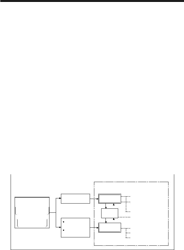
The following diagram outlines the peripheral devices and programs using a positioning software package, data creation, and A173UHCPU/A172SHCPUN/ A171SHCPUN processing.
IBM PC
+
 SW
SW SRX-GSV
 PE,
PE, SW
SW RN-GSV
 PE
PE
+
 SW
SW SRX-SV

 ,
, SW
SW RN-SV
RN-SV


1 − 1
1.SPECIFICATIONS OF MOTION SYSTEM COMPONENTS
•The sequence program written into the SCPU, the servo program or motion program written into the PCPU, and the positioning parameters are created after starting up corresponding positioning software package by the peripheral device.
•The peripheral device started up by the positioning software package can monitor the positioning control conditions of A173UHCPU/A172SHCPUN/ A171SHCPUN, execute the servo program or motion program, and perform a test such as JOG operation.
REMARKS
For information about a peripheral device and programming information for producing a sequence program and a special function unit, refer to each manual pertaining to the individual unit.
For information about creating motion programs, refer to the programming manual of the operating system used. For information about the operation of each peripheral software package, refer to each individual operating manuals.
In this manual, the following abbreviations are used.
Description |
Abbreviation |
|
|
A173UHCPU/A172SHCPUN/ A171SHCPUN Module |
A173UHCPU/A172SHCPUN/ |
||
A171SHCPUN or CPU module |
|||
|
|||
MR-H-BN,MR-J2S-B,MR-J2-B servo amplifier |
MR-H-BN/MR-J2S-B/MR-J2-B |
||
A172SENC manual pulse generator/synchronous encoder interface unit/module |
A172SENC |
||
Fast serial communication between motion controller and servo amplifier |
SSCNET*1 |
||
*1 SSCNET: Servo System Controller NETwork
1 − 2
1. SPECIFICATIONS OF MOTION SYSTEM COMPONENTS
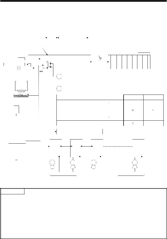
1.2 Overall Configuration of Motion System
1.2.1 A172SHCPUN/A171SHCPUN System Overall Configuration
|
|
|
|
|
|
|
|
|
|
|
|
|
|
|
*1 |
|
|
|
|
|
|
|
|
|
|
|
|
|
|
|
|
|
|
|
|
|
|
|
Motion slot |
Sequence module slot |
|
|
|||||||||||
|
|
|
|
|
|
|
|
|
|
|
|
|
|
|
|
|
|
|
|
|
|
|
|
|
|
|
|
Manual pulse generator/ |
|
|
|
switchLimit moduleoutput |
|
|
|
|
|
|
|
|
|
|
Extension cable |
||||||||||
|
synchronous encoder |
|
|
|
|
|
|
|
|
|
|
|
|
|
|
|||||||||||
|
interface module |
|
|
|
|
|
|
|
|
|
|
|
|
|
|
(A1SC |
B for |
|||||||||
|
|
|
|
|
|
|
|
|
|
|
|
|
|
|
|
|
|
|
|
|
|
|
|
|
A1S6 |
B |
Battery |
|
Motion CPU |
|
A172 |
|
A1S |
|
|
|
|
|
|
|
|
|
|
and A168B) |
|||||||||
|
|
|
|
|
|
|
|
|
|
|
|
|
||||||||||||||
|
|
|
|
|
|
|
|
|
|
|
|
|
(A1S |
NB |
||||||||||||
|
A6BAT |
|
|
|
|
|
|
|
|
SENC |
|
Y42 |
|
|
|
|
|
|
|
|
|
|
for A6 |
B) |
||
|
|
|
|
|
|
|
|
|
|
A1S input module or |
|
|
|
|||||||||||||
|
|
|
|
|
|
|
|
|
|
|
|
|
|
|
|
|
|
|
||||||||
|
|
|
|
|
|
|
|
|
|
|
|
|
|
|
|
|
|
|
|
|
||||||
Emergency stop input |
|
|
|
|
|
|
|
|
|
|
|
|
|
special function module |
|
|
|
|
|
|||||||
|
|
|
|
|
|
|
|
|
|
|
|
|
|
|
|
|
|
|
|
|
|
|
||||
|
|
|
|
|
|
|
|
|
|
|
|
|
|
|
|
|
|
|
|
|
|
|
|
|
|
|
|
|
|
|
|
|
|
|
|
|
|
|
|
|
|
|
|
|
|
|
|
|
|
|
|
|
|
100/200VAC
IBM PC (DOS)
 RS422
RS422
Teaching unit
A31TU-E/A30TU-E
RS422
Communication cable (A270CDCBL M/ A270BDCBL
  M)
M)
IBM PC (DOS,Windows)
SSCNET2
Main base unit(A178B-S1/A17 B)
B)
PManual pulse generator 1 (MR-HDP01)
Serial absolute synchronous encoder cable
E(MR-HSCBL M)
M)
Serial absolute synchronous encoder  1 (MR-HENC)
External input signals
 FLS upper stroke limit
 RLS lower stroke limit
 STOP signal
 DOG/CHANGE near-zero point dog/ changeover between speed and position
 TRA tracking
Electromagnetic brake command output
SSCNET cable |
|
|
d1 |
d2 |
d3 |
SSC I/F card/board (A30CD-PCF/A30BD-PCF) SSCNET1
GOT
Power supply module
Sequence extension base
 Up to one extension base unit for A1S6
 B
B
 Up to one extension base unit for A168B (GOT compatible)
 Up to one extension base unit for A6
 B
B
A171SHCPUN A172SHCPUN
4 |
8 |
1 |
1 |
|
|
dn |
*2 |
|
Termination |
|
resistance |
*1:No. of motion slots |
|
|
|
|
||||
|
|
|
|
|
|
|
|
|
|
A17 B |
1 |
|
M |
M |
M |
M |
|
|
A178B-S1 |
2 |
|
|||||
|
|
E |
E |
E |
E |
|||
|
|
|
|
|||||
*2:n:No. of control axes (max.) |
||||||||
|
|
|
|
|||||
|
|
|
|
|
|
MR-H-BN/MR-J2S-B/MR-J2-B model |
|
|
|
A171SHCPUN |
4 |
|
|
|
|
||
|
|
|
|
Servo amplifier |
|
|||
|
|
|
|
|
|
|
||
|
A172SHCPUN |
8 |
|
|
|
|
||
|
|
|
|
|
|
|||
|
|
|
|
|
|
|
|
|
SSCNET:Servo System Controller NETwork
POINTS
(1)When using the sequence extension base and bus connection type GOT, select the A168B as the sequence extension base. When not using the sequence extension base, you can connect the bus connection type GOT directly to the extension connector of the main base unit.
(2)When using a teaching unit A31TU-E with a dead-man switch, a dedicated connecting cable A31TUCBL03M is required between the CPU unit and A31TU-E connector. If the A31TU-E is connected directly to the RS422 connector of the CPU without using a dedicated cable, the A31TU-E will not operate at all. After disconnecting the A31TU-E, attach a short-circuit connector A31SHORTCON for A31TUCBL.
(3)In a motion module, a sequence A1S I/O modules can also be installed.
(4)Though the external input signals of A172SENC are reserved for eight axes, for A171SHCPUN, set those for the first half four axes (PX0 to PX0F).
1 − 3
1. SPECIFICATIONS OF MOTION SYSTEM COMPONENTS
 CAUTION
Configure safety circuits external to the controller or servo amplifier if their abnormal operation could cause axis motion in a direction other than the safe operating direction for the system. Ensure that the characteristics of other components used in a system match those of the controllers, servo amplifiers, and servo motors.
Set the parameters to values appropriate for the controllers, servo amplifiers, servo motors, regenerative resistor types, and system application. The protective functions may not work if the parameters are set incorrectly.
1 − 4
1. SPECIFICATIONS OF MOTION SYSTEM COMPONENTS
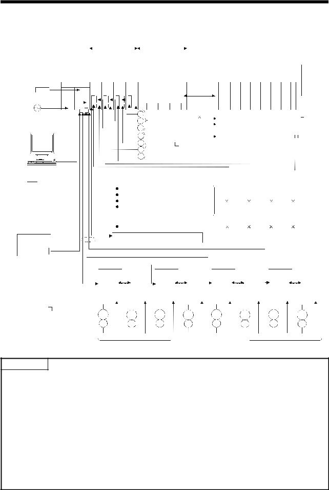
1.2.2 A173UHCPU System Overall Configuration
Battery A173UHCPU
A6BAT
Emergency stop input 
100/200VAC
IBM PC (DOS)
 RS422
RS422
Teaching unit
A31TU-E/A30TU-E
RS422
Communication cable (A270CDCBL  M/ A270BDCBL
  M)
M)
IBM PC (DOS,Windows)
*2
SSCNET4
SSC I/F card/board (A30CD-PCF/A30BD-PCF)
|
*1 |
|
|
|
|
|
|
|
|
Motion slot |
|
Sequence module slot |
|||||||
Manual pulse |
|
|
|
Main base unit |
|||||
|
|
|
(A178B-S3/ |
||||||
generator/ |
|
|
|
|
|||||
|
|
|
|
A178B-S2/ |
|||||
synchronous encoder |
|
|
|||||||
|
|
A178B-S1/ |
|||||||
interface module |
|
|
|
||||||
|
|
|
A17 B) |
||||||
|
|
|
|
|
|||||
A172 A172 |
A172 |
A172 |
|
|
|
|
|
|
|
|
|
|
|
|
|
|
|||
SENC SENC SENC SENC |
|
|
|
|
|
|
|||
A1S |
input |
module |
or |
|
|
||||
|
|
|
|
special function module |
|
||||
|
|
|
|
|
|
|
|
|
|
Extension cable (A1SC B for A1S6
 B
B
and A168B)
(A1S NB for A6
 B)
B)
GOT
Power supply module
|
P |
Manual pulse generator 3 |
Sequence extension base |
|
|
|
|
|||||||
|
P |
Up to one extension base unit for A1S6 B |
||||||||||||
|
(MR-HDP01) |
|
||||||||||||
|
|
Up to one extension base unit for A168B |
||||||||||||
|
|
|
||||||||||||
|
P |
|
|
|
||||||||||
|
|
|
|
(GOT compatible) |
|
|
|
|
||||||
|
|
Serial absolute synchronous |
|
|
|
|
||||||||
|
E |
Up to one extension base unit for A6 |
B |
|||||||||||
|
encoder cable |
|
||||||||||||
|
|
M) |
|
|
|
|
|
|
|
|
|
|
||
|
E |
(MR-HSCBL |
|
|
|
|
|
|
|
|
|
|
||
|
E |
Serial absolute synchronous encoder 4 |
|
|
|
|
|
|
||||||
|
E |
(MR-HENC) |
|
|
|
|
|
|
|
|
|
|
|
|
|
|
|
|
|
|
|
|
|
|
|
|
|
|
|
|
External input signals |
|
|
|
|
|
|
|
|
|
|
|
|
|
|
|
|
|
|
|
|
|
|
|
|
|
|
|
|
|
FLS upper stroke limit |
|
|
|
|
|
|
|
|
|
|
|
|
|
|
RLS lower stroke limit |
|
|
|
|
|
|
|
|
|
|
|
|
|
|
STOP signal |
|
|
|
8 |
|
8 |
|
8 |
|
8 |
|
||
|
DOG/CHANGE near-zero point dog/ |
|
|
|
|
|
|
|
|
|
|
|||
|
speed-position change |
|
|
|
|
|
|
|
|
|
|
|
|
|
|
|
|
|
|
|
|
|
|
|
|
|
|
||
|
TRA tracking *3 |
|
|
|
1 |
|
1 |
|
1 |
|
1 |
|
||
|
Electromagnetic brake command output |
|
|
|
|
|
|
|
|
|
|
|||
*2 |
|
SSCNET cable |
|
|
SSCNET4 |
|
|
|
|
|
|
|||
|
|
|
|
|
|
|
|
|
|
|||||
|
|
SSCNET3 |
|
|
|
|
|
|
|
|
|
|
||
|
SSCNET2 |
|
|
|
|
|
|
|
|
|
|
|
|
|
|
d1 |
d8 |
d9 |
d16 |
|
|
d17 |
d24 |
d25 |
|
d32 |
|||
SSCNET1
*1:No. of motion slots
A17 B |
1 |
M |
|
M |
|
M |
|
M |
|
A178B-S1 |
2 |
M |
M |
M |
M |
||||
|
|
|
|
|
|
|
|
||
|
|
E |
|
E |
|
E |
|
E |
|
A178B-S2 |
4 |
E |
E |
E |
E |
||||
|
|
|
|
|
|
|
|
|
|
A178B-S3 |
8 |
|
|
|
|
|
|
|
|
|
|
|
|
|
MR-H-BN/MR-J2S-B/MR-J2-B model |
|
|
||
|
|
|
|
|
|
|
|||
|
|
|
|
|
Servo amplifier, max. 32 axes |
|
|
||
|
|
|
|
|
|
|
SSCNET:Servo System Controller NETwork |
||
POINTS
(1)When using the sequence extension base and bus connection type GOT, select the A168B as the sequence extension base. When not using the sequence extension base, you can connect the bus connection type GOT directly to the extension connector of the main base unit.
(2)When using a teaching unit A31TU-E with a dead-man switch, a dedicated connecting cable A31TUCBL03M is required between the CPU unit and A31TU-E connector. If the A31TU-E is connected directly to the RS422 connector of the CPU without using a dedicated cable, the A31TU-E will not operate at all. After disconnecting the A31TU-E, attach a short-circuit connector A31SHORTCON for A31TUCBL.
(3)In a motion module, a sequence A1S I/O modules can also be installed.
*2 The A173UHCPU can use four channels of the SSCNET. When using the SSCNET card/board (A30CD-PCF/A30BD-PCF), connect it to the SSCNET4 and the servo amplifiers to the SSCNET1 to 3.
In this case, up to 24 axes of servo amplifiers can be connected. *3 TRA tracking enable can use any one point.
1 − 5

1. SPECIFICATIONS OF MOTION SYSTEM COMPONENTS
 CAUTION
Configure safety circuits external to the controller or servo amplifier if their abnormal operation could cause axis motion in a direction other than the safe operating direction for the system. Ensure that the characteristics of other components used in a system match those of the controllers, servo amplifiers, and servo motors.
Set the parameters to values appropriate for the controllers, servo amplifiers, servo motors, regenerative resistor types, and system application. The protective functions may not work if the parameters are set incorrectly.
1 − 6

1. SPECIFICATIONS OF MOTION SYSTEM COMPONENTS
1.3 Equipment in System
(1) Table of motion modules
|
|
|
|
Current |
|
||
Part Name |
Model Name |
Description |
Consumption |
Remarks |
|||
|
|
|
|
5 VDC (A) |
|
||
|
A173UHCPU(-S1) |
Max. 32 axes control |
1.90 |
|
|||
CPU module |
A172SHCPUN |
Max. 8 axes control |
1.63 |
|
|||
|
A171SHCPUN |
Max. 4 axes control |
1.63 |
|
|||
|
A172B |
|
One motion module slot and one sequence module slot |
|
|
|
|
|
A175B |
|
One motion module slot and four sequence module slots |
|
|
|
|
|
A178B |
|
One motion module slot and seven sequence module |
|
|
|
Sequence extension |
|
|
slots |
|
|
|
||
Main base unit |
|
|
|
|
|
connector as |
|
A178B-S1 |
|
Two motion module slots and six sequence module slots |
|
|
|
||
|
|
|
|
|
accessory |
||
|
A178B-S2 |
|
Four motion module slots and four sequence module slots |
|
|
|
|
|
|
|
|
|
|
||
|
A178B-S3 |
|
Eight motion module slots and zero sequence module |
|
|
|
|
|
|
slots |
|
|
|
|
|
|
|
|
|
|
|
|
|
|
A1S65B |
|
Extension power and five slots for system up to one |
|
|
|
|
|
|
extension stage |
|
|
|
|
|
Sequence |
|
|
|
|
|
|
|
|
|
Extension power and eight slots for system up to one |
|
|
|
|
|
extension base |
A1S68B |
|
|
|
|
|
|
|
extension stage |
|
|
|
|
||
unit |
|
|
|
|
|
|
|
A168B |
|
Extension power and eight slots for system up to one |
|
|
|
Extension connector |
|
|
|
|
|
|
|||
|
|
extension stage |
|
|
|
as accessory |
|
|
|
|
|
|
|
||
|
A1SC01B |
|
Flat cable of 55 mm (2.17 in) in length |
|
|
|
For extension to the |
|
|
|
|
|
right side |
||
|
|
|
|
|
|
|
|
|
A1SC03B |
|
Length 330 mm (13 in) |
|
|
|
|
|
A1SC07B |
|
Length 700 mm (27 in) |
|
|
|
|
|
A1SC12B |
|
Length 1200 mm (47 in) |
|
|
|
|
|
|
|
|
|
|
||
Extension cable |
A1SC30B |
|
Length 3000 mm (118 in) |
|
|
|
|
|
A1SC60B |
|
Length 6000 mm (236 in) |
|
|
|
|
|
A1SC05NB |
|
Length 450 mm (17 in) AnN extension base cables |
|
|
|
|
|
A1SC07NB |
|
Length 700 mm (27 in) AnN extension base cables |
|
|
|
For A6 B |
|
A1SC30NB |
|
Length 3000 mm (118 in) AnN extension base cables |
|
|
|
|
|
|
|
|
|
|
||
|
A1SC50NB |
|
Length 5000 mm (197 in) AnN extension base cables |
|
|
|
|
Manual pulse |
|
|
32 points I/O signals |
|
|
|
|
generator |
|
|
(FLS, RLS, STOP, DOG/CHANGE× 8) |
|
|
|
|
/synchronous |
A172SENC |
|
Tracking input 1 point |
0.42 |
|
||
encoder |
|
Electromagnetic brake control output 1 point |
|
||||
|
|
|
|
|
|
||
interface |
|
|
Manual pulse generator interface 1 point |
|
|
|
|
module |
|
|
Synchronous encoder interface 1 point |
|
|
|
|
|
|
|
|
|
|
||
Limit output unit |
A1SY42 |
|
Transistor output 64 points, 12/24 VDC, 0.1A |
0.93 |
|
||
Manual pulse |
MR-HDP01 |
|
4.5 VDC to 13.2 VDC 25 PLS/rev, 100 PLS/rev at |
0.06 |
|
||
generator |
|
magnification of 4 |
|
||||
|
|
|
|
|
|
||
Serial absolute |
|
|
Resolution: 16384 PLS/rev, |
|
|
|
|
synchronous |
MR-HENC |
|
0.15 |
|
|||
|
Permitted rotational speed: 4300r/min |
|
|||||
encoder |
|
|
|
|
|
|
|
|
|
|
|
|
|
|
|
|
|
|
Synchronous encoder and A172SENC connector cables: |
|
|
|
|
Serial absolute |
|
|
2 m (6.56 ft.), 5 m (16.4 ft.), 10 m (32.8 ft.), 20 m (65.6 |
|
|
|
|
synchronous |
MR-HSCBL |
M |
ft.), 30 m (98.4 ft.) |
|
|
|
|
|
|
|
|
||||
encoder cable |
|
|
(Same cables as encoder cables for HA-LH K, HC- |
|
|
|
|
|
|
|
SF/RF/UF(2000r/min)series motors.) |
|
|
|
|
Battery |
A6BAT |
|
For CPU module memory back-up |
|
|
|
|
|
(Sequence program/servo program) |
|
|
|
|
||
|
|
|
|
|
|
|
|
|
A30TU-E |
|
For SV13, cable length 5 m (16.4 ft) |
0.22 |
|
||
|
A31TU-E |
|
For SV13 with deadman switch, cable length 5 m (16.4 |
0.22 |
|
||
|
|
ft) |
|
||||
|
|
|
|
|
|
|
|
|
|
|
For SV51 with deadman switch, cable length 5 m (16.4 |
|
|
|
|
Teaching unit |
A31TU-RE |
|
ft) |
0.22 |
|
||
|
|
|
(Need A31TUCBL03M and A31SHORTCON.) |
|
|
|
|
|
A31TUCBL03M |
CPU module to A31TU-E connector cable of 3 m (9.84 ft.) |
|
|
|
For control panel |
|
|
A31SHORTCON |
Short-circuit connector for A31TUCBL |
|
|
|
When A31TU-E is |
|
|
|
|
|
||||
|
|
|
|
not connected |
|||
|
|
|
|
|
|
|
|
SSC I/F board |
A30BD-PCF |
|
ISA bus loading type, 2 channels/board |
|
|
|
|
SSC I/F card |
A30CD-PCF |
|
PCMCIA TYPE II, 1 channel/card |
|
|
|
|
SSC I/F board |
A270BDCBL |
M |
3 m (9.84 ft.), 5 m (16.4 ft.), 10 m (32.8 ft.) for |
|
|
|
|
cable |
A30BD-PCF |
|
|
|
|
||
|
|
|
|
|
|
||
SSC I/F card |
A270CDCBL |
M |
3 m (9.84 ft.), 5 m (16.4 ft.), 10 m (32.8 ft.) for |
|
|
|
|
cable |
A30CD-PCF |
|
|
|
|
||
|
|
|
|
|
|
||
1 − 7
1. SPECIFICATIONS OF MOTION SYSTEM COMPONENTS
(2) Table of servo amplifier modules
Part Name |
Model Name |
|
Description |
|||
|
Servo amplifier |
MR-H |
BN |
|
50 W to 22 kW |
|
|
MR-H |
KBN |
30 kW to 55 kW |
|||
|
|
|||||
|
Battery |
MR-BAT |
|
Backup for absolute position detection |
||
|
Termination |
MR-TM |
|
|
Fitted to the last amplifier of SSCNET |
|
|
connector |
|
|
|||
|
|
|
|
|
|
|
|
|
MR-PB |
|
|
External regenerative resistor 10 W to 500 W |
|
|
|
MR-H |
KB |
|
Regenerative power 600 W |
|
|
Regenerative |
Standard accessory |
||||
MR-H-BN |
resistor |
MR-PB |
-4 |
|
External regenerative resistor 1300, 3900 W |
|
|
FR-BU |
|
|
Brake unit 15/30/55K |
||
series |
|
|
|
|||
|
|
FR-RC |
|
|
Power return converter 15/30/55K |
|
|
|
|
|
|
For connection of CPU module and MR-H-BN, for connection of MR-H-BN and |
|
|
SSCNET cable |
MR-HBUS |
M |
MR-H-BN |
|
|
|
|
|
|
|
0.5 m(1.64 ft), 1 m (3.28ft), 5 m (16.4 ft) |
|
|
Encoder cable |
MR-HSCBL |
M |
For connection of HA-LH K, HC-SF/RF/UF (2000r/min) series motor and MR-H- |
||
|
|
|
|
BN |
|
|
|
*2 |
MR-EN1CBL M-H |
|
|||
|
|
2 m (16.4 ft), 5 m (16.4 ft), 10 m (32.8 ft), 20 m (65.6 ft), 30 m (98.4 ft) |
||||
|
Encoder |
MR-JSCNS |
|
For HA-LH |
K, HC-SF/RF/UF (2000r/min) series motors |
|
|
connector set |
MR-EN1CNS |
Amplifier side connector and encoder side connector set |
|||
MR-J2S-B |
Servo amplifier |
MR-J2S- B*1 |
50 W to 7 kW, three-phase 200 to 230 VAC or single-phase 230 VAC |
|||
series |
MR-J2S- B1 |
50 W to 400 W, single-phase 100 to 120 VAC |
||||
MR-J2-B |
Servo amplifier |
MR-J2- |
B |
|
50 W to 3.5 kW |
|
series |
|
|||||
|
|
|
|
|
|
|
|
Battery |
MR-BAT |
|
Backup for absolute position detection |
||
|
Termination |
MR-A-TM |
|
Fitted to the last amplifier of SSCNET |
||
|
connector |
|
||||
|
|
|
|
|
|
|
|
|
|
|
|
For connection of CPU module and MR-J2S-B/MR-J2-B, for connection of MR-H- |
|
|
|
MR-J2HBUS |
M-A |
BN and MR-J2S-B/MR-J2-B |
||
|
SSCNET cable |
|
|
|
0.5 m(1.64 ft), 1 m (3.28ft), 5 m (16.4 ft) |
|
|
|
MR-J2HBUS |
M |
For connection of MR-J2S-B/MR-J2-B and MR-J2S-B/MR-J2-B |
||
|
|
0.5 m(1.64 ft), 1 m (3.28ft), 5 m (16.4 ft) |
||||
|
|
|
|
|
||
Equipment |
|
MR-JHSCBL |
M-L |
Standard |
For connection of HC-SFS/RFS/UFS (2000r/min) series motor and |
|
common to |
|
cable |
MR-J2S-B, and for connection of HC-SF/RF/UF (2000r/min) series |
|||
|
|
|
|
|||
MR-J2S-B |
|
MR-JHSCBL |
M-H |
Long flexing |
motor and MR-J2-B |
|
and |
|
|
|
|
2 m (6.56 ft), 5 m (16.4 ft), 10 m (32.8 ft), 20 m (65.6 ft), |
|
|
MR-ENCBL |
M-H |
life cable |
|||
MR-J2-B |
Encoder cable |
30 m (98.4 ft) |
||||
series |
*2 |
MR-JCCBL |
M-L |
Standard |
For connection of HC-MFS/KFS/UFS (3000r/min) series motor and |
|
|
||||||
|
|
cable |
MR-J2S-B, and for connection of HC-MF/UF (3000r/min), HA-FF |
|||
|
|
|
|
|
||
|
|
|
|
|
Long flexing |
series motor and MR-J2-B |
|
|
MR-JCCBL |
M-H |
2 m (6.56 ft), 5 m (16.4 ft), 10 m (32.8 ft), 20 m (65.6 ft), |
||
|
|
|
|
|
life cable |
30 m (98.4 ft) |
|
|
|
|
|
|
|
|
|
MR-J2CNS |
|
For HC-SF/RF/UF (2000r/min), HC-SFS/RFS/UFS (2000r/min) series motors |
||
|
Encoder |
MR-ENCNS |
|
Amplifier side connector and encoder side connector set |
||
|
connector set |
MR-J2CNM |
|
For HC-MF/UF (3000r/min), HA-FF, HC-MFS/KFS/UFS (3000r/min) series motors |
||
|
|
|
Amplifier side connector and encoder side connector set |
|||
|
|
|
|
|
||
*1: 5kW and 7kW are scheduled for release.
*2: Long distance cable or cable without connector (cable only) is also available. Avoid using a short cable as it will cause a position shift or the like.
1 − 8
1. SPECIFICATIONS OF MOTION SYSTEM COMPONENTS
(3)Table of software package
(a) Motion function
|
|
|
|
Peripheral Software Package |
|
Main OS Software Package Model Name |
|
||||||||||
|
Peripheral |
|
|
Applicable version |
|
|
|
|
|
|
|
Teaching |
|||||
Use |
|
|
|
|
|
For |
For |
For |
For |
||||||||
Devices |
|
Model Name |
For |
function |
|||||||||||||
|
|
|
|
|
|
|
|
|
|||||||||
|
|
A172SH/ |
A173UH |
A172SH |
A171SH |
||||||||||||
|
|
|
|
|
A173UH |
|
|||||||||||
|
|
|
|
|
A171SH |
|
|
|
|
|
|
|
|
||||
|
|
|
|
|
|
|
|
|
|
|
|
|
|
|
|
||
|
|
DOS |
Japanese |
SW2SRX-GSV13P |
From 0AC on |
00T or later |
SW2SRX- |
SW0SRX- |
SW0SRX- |
|
|||||||
For conveyor |
|
English |
SW2SRX-GSV13PE |
From 00J on |
00F or later |
SV13B |
SV13D |
SV13G |
|
||||||||
|
|
|
|||||||||||||||
assembly |
IBM PC/AT |
NT/ |
Japanese |
SW3RNC-GSV |
From 00F on |
00E or later |
SW2SRX- |
SW2SRX- |
SW0SRX- |
|
|||||||
(SV13) |
|
|
|
|
|
|
|
|
|||||||||
|
|
|
Without |
Without |
|
||||||||||||
|
98 |
English |
SW3RNC-GSVE |
SV13B |
SV13D |
SV13G |
|
||||||||||
|
|
restriction |
restriction |
|
|||||||||||||
|
|
|
|
|
|
|
|
|
|
|
|
|
|||||
|
|
|
|
|
|
|
|
|
|
|
|
|
|
|
|
Yes |
|
For motion |
|
|
Japanese |
SW3RNC-GSV |
From 00F on |
Without |
|
|
|
|
|
|
|
||||
SFC- |
|
|
restriction |
|
|
|
|
|
|
|
|
||||||
|
|
|
|
|
|
|
|
|
|
|
|
|
|
|
|||
compatible |
IBM PC/AT |
NT/ |
|
|
|
|
|
|
SW3RN- |
SW3RN- |
|
|
|
|
|||
conveyor |
98 |
English |
SW3RNC-GSVE |
Without |
Without |
SV13B |
SV13D |
|
|
|
|
||||||
assembly |
|
|
restriction |
restriction |
|
|
|
|
|
|
|
|
|||||
|
|
|
|
|
|
|
|
|
|
|
|
||||||
(SV13) |
|
|
|
|
|
|
|
|
|
|
|
|
|
|
|
|
|
|
|
|
|
|
|
|
|
|
|
|
|
|
|
|
|
|
|
|
|
|
Japanese |
SW2SRX-GSV22P |
From 0AC on |
00T or later |
|
|
|
|
|
|
|
|
|||
|
|
|
|
|
|
|
|
|
|
|
|
|
|
|
|
||
|
|
|
SW0SRX-CAMP |
From 00B on |
00B or later |
|
|
|
|
|
|
|
|
||||
|
|
|
|
|
|
|
|
|
|
|
|
||||||
|
|
DOS |
|
|
|
|
|
|
|
|
|
|
|
|
|
|
|
For automatic |
|
|
SW2SRX-GSV22PE |
From 00J on |
00F or later |
|
|
|
|
|
|
|
|
||||
|
|
English |
|
|
|
|
|
SW2SRX- |
SW0SRX- |
SW0SRX- |
|
||||||
|
|
|
Without |
Without |
|
||||||||||||
machinery |
IBM PC/AT |
|
SW0IX-CAMPE |
|
|||||||||||||
|
|
restriction |
restriction |
SV22A |
SV22C |
SV22F |
|
||||||||||
(SV22) |
|
|
|
|
|
||||||||||||
|
|
|
|
|
|
|
|
|
|
|
|
|
|
|
|
||
|
NT/ |
Japanese |
SW3RNC-GSV |
From 00F on |
00E or later |
|
|
|
|
|
|
|
|
||||
|
|
|
|
|
|
|
|
|
|
||||||||
|
|
|
|
|
|
|
|
|
|
|
|
|
|
|
|
||
|
|
|
|
Without |
Without |
|
|
|
|
|
|
|
No |
||||
|
|
98 |
English |
SW3RNC-GSVE |
|
|
|
|
|
|
|
||||||
|
|
restriction |
restriction |
|
|
|
|
|
|
|
|||||||
|
|
|
|
|
|
|
|
|
|
|
|
|
|||||
|
|
|
|
|
|
|
|
|
|
|
|
|
|
|
|
|
|
For motion |
|
|
Japanese |
SW3RNC-GSV |
From 00F on |
Without |
|
|
|
|
|
|
|
|
|||
SFC- |
|
|
restriction |
|
|
|
|
|
|
|
|
||||||
|
|
|
|
|
|
|
|
|
|
|
|
|
|
|
|||
compatible |
IBM PC/AT |
NT/ |
|
|
|
|
|
|
SW3RN- |
SW3RN- |
|
|
|
|
|||
|
|
|
|
|
|
|
|
|
|
||||||||
automatic |
98 |
English |
SW3RNC-GSVE |
Without |
Without |
SV22A |
SV22C |
|
|
|
|
||||||
machinery |
|
|
restriction |
restriction |
|
|
|
|
|
|
|
|
|||||
|
|
|
|
|
|
|
|
|
|
|
|
||||||
(SV22) |
|
|
|
|
|
|
|
|
|
|
|
|
|
|
|
|
|
|
|
|
|
|
|
|
|
|
|
|
|
|
|
|
|
|
|
For machine |
|
|
|
|
|
|
|
|
SW2SRX- |
SW0SRX- |
SW0SRX- |
|
|||||
tool peripheral |
IBM PC/AT |
DOS |
Japanese |
SW2SRX-GSV43P |
From 00T on |
00J or later |
No |
||||||||||
SV43A |
SV43C |
SV43F |
|||||||||||||||
(SV43) |
|
|
|
|
|
|
|
|
|
||||||||
|
|
|
|
|
|
|
|
|
|
|
|
|
|
|
|
||
|
|
|
|
|
|
|
|
|
|
|
|
|
|
|
|||
For dedicated |
IBM PC/AT |
DOS |
Japanese |
SW2SRX-GSV51P |
|
|
|
00E or later |
|
|
|
SW0SRX- |
SW0SRX- |
Yes |
|||
robot (SV51) |
|
|
|
|
|
|
SV51D |
SV51G |
|||||||||
|
|
|
|
|
|
|
|
|
|
|
|
||||||
|
|
|
|
|
|
|
|
|
|
|
|
|
|
|
|
|
|
1 − 9
1. SPECIFICATIONS OF MOTION SYSTEM COMPONENTS
1.4 General Specifications
|
|
Table 1.1 Generation Specifications |
|
|
|
|
||||
|
|
|
|
|
|
|
|
|
|
|
Item |
|
|
|
Specification |
|
|
|
|
||
Operating ambient |
|
|
|
0 to 55° C |
|
|
|
|
||
temperature |
|
|
|
|
|
|
|
|||
|
|
|
|
|
|
|
|
|
|
|
|
|
|
|
|
|
|
|
|
|
|
Storage ambient |
|
|
|
-20 to 75° C |
|
|
|
|
||
temperature |
|
|
|
|
|
|
|
|||
|
|
|
|
|
|
|
|
|
|
|
|
|
|
|
|
|
|
|
|
|
|
Operating ambient |
|
|
10% to 90%RH, no condensation |
|
||||||
humidity |
|
|
|
|||||||
|
|
|
|
|
|
|
|
|
|
|
Storage ambient |
|
|
10% to 90%RH, no condensation |
|
||||||
humidity |
|
|
|
|||||||
|
|
|
|
|
|
|
|
|
|
|
|
|
Frequency |
|
Acceleration |
Amplitude |
Number of Sweeps |
||||
Vibration resistance |
Conforms to JIS C |
10 to 55Hz |
|
|
|
|
0.075mm |
10 |
||
0911*2 |
|
|
|
|
(0.003 in) |
|||||
|
|
|
|
|||||||
|
|
|
|
|
|
(1 octave/minute)*1 |
||||
|
|
55 to 150Hz |
|
9.8m/s2 |
|
|
|
|||
|
|
|
|
|
|
|
||||
Shock resistance |
Conforms to JIS C 0912 (98m/s2 (10g), 3 directions, 3 times)*2 |
|
|
|
|
|||||
Noise resistance |
(1) Noise voltage: 1500Vpp, noise amplitude: 1 s, noise frequency: 25 to 60 Hz, with a noise simulator |
|||||||||
(2) Noise voltage : IEC801-4, 2 kV |
|
|
|
|
|
|
|
|
||
|
|
|
|
|
|
|
|
|
||
Withstand voltage |
2830VAC rms/3 cycles across all inputs/LG and all outputs/FG (altitude 2000m (6557.38ft.)) |
|||||||||
|
|
|||||||||
Insulation resistance |
5M or more by 500VDC insulation resistance tester across all inputs/LG and all outputs/FG |
|||||||||
|
|
|
||||||||
Ground |
Class 3 grounding. Connect to enclosure when grounding is impossible. |
|
||||||||
Operating environment |
No corrosive gas, low dust |
|
|
|
|
|
|
|
|
|
|
|
|
|
|
|
|
|
|
|
|
Cooling method |
Natural cooling. |
|
|
|
|
|
|
|
|
|
REMARKS
*1 An “octave” refers to an increase or decrease in frequency by a factor of two. For example, the following are all octaves: 10 Hz to 20 Hz, 20 Hz to 40 Hz, 40 Hz to 20 Hz, and 20 Hz to 10 Hz.
Refer to “CHAPTER 2 DESIGN” for the installation environment and mounting instructions.
*2 JIS: Japan Industrial Standards
 WARNING
 Class 3 grounding should be used. The motion controller should not share a common ground with any other equipment. The ground terminal is located on the motion controller module terminal block. (See Section 1.5.2.)
 CAUTION
 The motion controller must be stored and operated under the conditions listed in the table of specifications above.
 Disconnect the power cables from the motion controller if it is to remain unused for a long period of time.
 Insert a controller or servo amplifier into the static-proof vinyl bag for storage.
Consult the system service or service station before storing equipment for a long period of time.
1 − 10

1. SPECIFICATIONS OF MOTION SYSTEM COMPONENTS
1.5 Specifications and Settings of Components
1.5.1 A173UHCPU/A172SHCPUN/A171SHCPUN
(1) Basic specifications of A173UHCPU, A172SHCPUN and A171SHCPUN
|
Item |
|
|
|
A173UHCPU(-S1) |
A172SHCPUN |
|
A171SHCPUN |
||||||
|
No. of control axes |
|
|
|
|
32-axes |
|
8-axes |
|
4-axes |
||||
|
|
SV13 |
|
|
3.5 ms/1 to 20 axes |
|
|
|
|
|||||
|
|
|
|
7.1 ms/21 to 32 axes |
|
|
|
|
||||||
Motion |
Computing |
|
|
|
|
|
|
|
||||||
|
|
|
3.5 ms/1 to 12 axes |
3.5 ms/1 to 8 axes |
|
3.5 ms/1 to 4 axes |
||||||||
|
frequency |
|
|
|
|
|||||||||
|
SV22 |
|
|
7.1 ms/13 to 24 axes |
|
|
|
|
||||||
|
|
|
|
|
|
|
|
|||||||
|
|
|
|
14.2 ms/25 to 32 axes |
|
|
|
|
||||||
|
|
|
|
|
|
|
|
|
|
|
Equivalent to |
|
|
|
|
Sequencer CPU |
|
|
Equivalent to A3UCPU |
reinforced I/O |
|
Equivalent to |
|||||||
|
|
|
memory of |
|
A2SHCPU |
|||||||||
|
|
|
|
|
|
|
|
|
|
|
|
|||
|
|
|
|
|
|
|
|
|
|
|
A2SHCPU |
|
|
|
|
Processing speed |
Direct |
|
|
|
|
|
|
|
|
|
0.25 to 1.9 |
s/step |
|
|
method |
|
|
|
|
|
|
|
|
|
||||
|
( s) (Sequence |
|
|
|
|
|
|
|
|
|
|
|
|
|
|
Refresh |
|
|
|
|
|
|
|
|
|
|
|
|
|
|
instruction) |
|
|
0.15 |
|
s/step |
|
|
0.25 s/step |
|||||
|
method |
|
|
|
|
|
||||||||
|
|
|
|
|
|
|
|
|
|
|
|
|
|
|
|
No. of I/O points |
|
|
|
|
8192 points |
|
|
2048 points |
|||||
|
No. of real I/O points *1 |
|
|
|
2048 points |
|
1024 points |
|
512 points |
|||||
PC |
|
|
Standard |
|
192k bytes (Equivalent to |
192k bytes |
|
64k bytes |
||||||
|
|
|
|
|
|
A3NMCA-24) |
|
|||||||
|
Memory capacity (built-in RAM) |
|
|
|
|
|
(Equivalent to |
|
(Equivalent to |
|||||
|
|
|
|
768k bytes (Equivalent to |
|
|||||||||
|
|
|
-S1 |
|
|
A3NMCA-24) |
|
A3NMCA-8) |
||||||
|
|
|
|
|
|
|
A3AMCA-96) |
|
||||||
|
|
|
|
|
|
|
|
|
|
|
|
|||
|
Program capacity |
|
|
|
|
Max. 30k steps |
Max. 30k steps |
|
Max. 14k steps |
|||||
|
(Main sequence) |
|
|
|
|
|
||||||||
|
|
|
|
|
|
|
|
|
|
|
|
|
|
|
|
No. of file register (R) |
|
|
|
|
|
|
|
Max. 8192 registers |
|
|
|
||
|
No. of extension file register |
Standard |
|
|
Max. 10 blocks |
Max. 10 blocks |
|
Max. 2 blocks |
||||||
|
block *2 |
|
-S1 |
|
|
|
Max. 46 blocks |
|
||||||
|
No. of sequencer extension |
|
|
|
|
|
|
|
Max. one |
|
|
|
||
|
base units |
|
|
|
|
|
|
|
|
|
|
|
||
|
|
|
|
|
|
|
|
|
|
|
|
|
|
|
|
Pulser synchronous encoder |
|
|
|
A172SENC |
4 |
|
A172SENC 1 |
||||||
|
(Corresponding to external signal input |
(Corresponding to external signal input |
||||||||||||
|
interface unit |
|
||||||||||||
|
|
|
|
|
32-axes) |
|
|
8-axes) |
||||||
|
|
|
|
|
|
|
|
|||||||
|
|
|
|
|
|
|
|
|
|
|
2CH. |
|
|
|
System |
|
|
|
|
|
|
|
|
|
|
SSCNET1..... For connection of servo |
|||
No. of SSCNET I/F |
|
|
|
|
4CH. |
|
|
amplifier |
|
|||||
configuration |
|
|
|
|
|
|
|
|||||||
|
|
|
|
|
|
|
|
|
|
SSCNET2..... For personal computer link |
||||
|
|
|
|
|
|
|
|
|
|
|
||||
|
|
|
|
|
|
|
|
|
|
|
|
dedicated |
||
|
Teaching unit (OS |
A30TU-E |
|
|
|
|
|
|
|
|
|
|
|
|
|
with teaching |
A31TU-E |
|
|
|
|
|
|
|
(With dead-man switch) |
|
|||
|
function) |
|
|
|
|
|
|
|
|
|||||
|
|
|
|
|
|
|
|
|
|
|
|
|
|
|
|
Sequence program, parameter |
After starting A173UHCPU and reading |
After starting A172SH/A171SH and |
|||||||||||
|
Servo program |
|
||||||||||||
|
|
a file, those created by A273UHCPU |
reading a file, those created by |
|||||||||||
|
Mechanism program (SV22) |
|||||||||||||
|
(32-axes) can be used as it is. |
A171SCPU can be used as it is. |
||||||||||||
|
Parameter |
|
||||||||||||
|
|
|
|
|
|
|
|
|
|
|
|
|
|
|
|
|
|
|
|
|
|
|
|
|
|
|
|||
Compatibility |
|
|
|
|
|
|
|
|
|
|
By making sure of system setting screen |
|||
|
|
|
|
|
|
|
|
|
|
after being started up by A172SH/A171SH |
||||
|
|
|
|
|
|
|
|
|
|
|
||||
|
|
|
|
|
|
|
|
|
|
|
and reading a file, changeover below is |
|||
|
System setting |
|
Must be set anew. |
|
|
|
|
carried out: |
A172SH/A171SHCPUN |
|||||
|
|
|
|
|
|
|
|
|
|
|
A171SCPU |
|||
|
|
|
|
|
|
|
|
|
|
|
A171SENC |
A172SENC |
||
|
|
|
|
|
|
|
|
|
|
|
now the system is ready for operation. |
|||
|
|
|
|
|
|
|
|
|
|
|
|
|
|
|
Outside dimensions |
|
|
|
130 |
113.3 |
93.6 (5.12 |
4.46 3.69) |
unit = mm (inch) |
||||||
|
|
|
|
|
|
|
|
|
|
|
|
|
|
|
Weight (kg (lb)) |
|
|
|
|
|
|
|
|
|
0.85 (1.87) |
|
|
|
|
|
|
|
|
|
|
|
|
|
|
|||||
|
*1 The real I/O points can be used within the range of one extension base. |
|
||||||||||||
|
*2 No. of extension file register blocks varies depending on the setting of program capacity, No. of file |
|||||||||||||
|
registers, and No. of comments. |
|
|
|
|
|
|
|
|
|||||
1 − 11

1.SPECIFICATIONS OF MOTION SYSTEM COMPONENTS
(2)Functions and performance specifications of PCPU
The performance specifications and functions of the PCPU depend on the motion function OS model installed in the CPU module.
Refer to the programming manual of the motion functions installed in the CPU module.
1 − 12
1. SPECIFICATIONS OF MOTION SYSTEM COMPONENTS
(3)SCPU performance specifications and functions
(a)SCPU performance specifications
As the SCPU performance specifications differ according to the operating system used, refer to the appropriate OS Programming Manual for details.
Table 1.2 Table of SCPU Performance Specifications
|
|
Item |
|
A173UHCPU(-S1) |
A172SHCPUN |
A171SHCPUN |
|||||||
Control method |
|
|
|
|
|
|
Stored programs repeated operation |
||||||
I/O control method |
|
|
Refresh method |
Refresh method/direct method (selectable) |
|||||||||
Programming language |
|
|
|
|
|
|
Sequence control dedicated language |
||||||
|
|
|
(Relay symbol language, logic symbol language, MELSAP-II (SFC)) |
||||||||||
|
|
|
|
|
|||||||||
|
|
Sequence instructions |
|
|
|
22 |
26 |
|
|
||||
Number of instructions |
Basic instructions |
|
|
|
252 |
131 |
|
||||||
Special instructions |
|
|
|
204 |
106 |
|
|||||||
|
|
|
|
|
|
||||||||
|
|
Motion dedicated instructions |
|
|
|
4 |
|
4 |
|
|
|||
Processing speed ( s) |
Direct method |
|
|
|
|
|
|
0.25 to 1.9 |
s/step |
||||
|
|
|
|
|
|
||||||||
(sequence instructions) |
Refresh method |
0.15 |
|
s/step |
0.25 s/step |
||||||||
No. of I/O points |
|
8192 points (X/Y0 to 1FF) |
2048 points (X/Y0 to X/Y7FF) |
||||||||||
No. of real I/O points *5 |
|
2048 points (X/Y0 to 7FF) |
1024 points (X/Y0 to |
512 points (X/Y0 to X/Y1FF) |
|||||||||
|
|
|
|
|
|
|
|
|
X/Y3FF) |
|
|
||
Watchdog timer (WDT) |
|
|
200 ms fixed |
10 to 2000 ms |
|||||||||
|
|
|
|
|
|
|
192k bytes |
|
|
|
|
|
|
|
|
|
Standard |
|
(Equivalent to |
|
|
|
|
|
|||
Memory capacity (internal RAM) |
|
|
|
A3NMCA-24) |
192k bytes |
|
64k bytes |
||||||
|
|
|
|
768k bytes |
|
||||||||
|
|
|
|
|
|
|
|
|
|
|
|
||
|
|
|
-S1 |
|
(Equivalent to |
|
|
|
|
|
|||
|
|
|
|
|
|
|
A3AMCA-96) |
|
|
|
|
|
|
|
|
Main sequence program |
|
|
|
|
|
Max. 30 k steps |
|
Max. 14k steps |
|||
Program capacity |
Sub-sequence program |
|
Max. 30k steps |
None |
|
None |
|||||||
|
|
Micro computer program |
|
|
None |
Max. 58k bytes |
|
Max. 26k bytes |
|||||
|
No. of internal relays (M) *1 |
7144 points (M0 to M999, |
1000 points (M0 to M999) |
||||||||||
|
|
|
|
M2048 to M8191) |
|
|
|
|
|
||||
|
No. of latch relays (L) |
|
|
|
|
|
|
1048 points (L1000 to L2047) |
|
|
|||
|
No. of step relays (S) |
|
|
|
|
|
|
0 point (none at initial status) |
|
|
|||
|
No. of link relays (B) |
8192 points (B0 to B1FFF) |
1024 points (B0 to B3FF) |
||||||||||
|
|
Points |
|
|
|
|
|
|
256 points |
|
|
||
|
|
|
|
|
|
|
|
|
|
|
|
*3 |
|
|
|
|
|
|
|
|
|
|
Time setting |
|
Device |
|
|
|
Timers (T) |
|
|
100 ms timer |
0.1 to 3276.7s |
|
|
T0 to T199 |
|
||||
|
Specifications |
|
|
10 ms timer |
0.01 to 327.67s |
|
|
T200 to T255 |
|
||||
|
|
|
|
|
|
||||||||
|
|
|
|
100ms retentive timer |
0.1 to 3276.7s |
|
|
No initial value |
|
||||
|
|
|
|
|
|
|
|
|
|
|
|
|
|
|
|
|
|
|
|
|
|
|
Set with parameters |
|
|
||
|
|
|
|
|
|
|
|
|
|
|
|
|
|
|
|
Points |
|
|
|
|
|
|
256 points |
|
|
||
|
|
|
|
|
|
|
|
|
|
|
|
*4 |
|
|
|
|
|
|
|
|
|
|
Setting range |
|
Device |
|
|
Device |
Counters (C) |
Specifications |
|
Normal counter |
1 to 32767 |
|
|
C0 to C255 |
|
||||
|
|
|
Interrupt program counter |
1 to 32767 |
|
|
C224 to C255 |
|
|||||
|
|
|
|
|
|
|
|||||||
|
|
|
|
|
(No initial value) |
|
|||||||
|
|
|
|
|
|
|
|
|
|
|
|
|
|
|
|
|
|
|
|
|
|
|
|
|
|
||
|
|
|
|
|
|
|
|
|
Set with parameters |
|
|
||
|
|
|
|
|
|
|
|
||||||
|
No. of data registers (D) *1 |
8192 points (D0 to D8191) |
1024 points (D0 to D1024) |
||||||||||
|
No. of link registers (W) |
8192 points (W0 to W1FFF) |
1024 points (W0 to W3FF) |
||||||||||
|
No. of annunciators (F) |
2048 points (F0 to F2047) |
256 points (F0 to F255) |
||||||||||
|
No. of file registers (R) |
|
|
|
|
|
Max. 8192 points (R0 to R8191) (set with parameters) |
||||||
|
No. of accumulators (A) |
|
|
|
|
|
|
2 points (A0, A1) |
|
|
|||
|
No. of index registers (V, Z) |
|
14 points |
2 points (V, Z) |
|||||||||
|
|
(V, V1 to V6, Z, Z1 to Z6) |
|||||||||||
|
|
|
|
|
|
|
|
|
|||||
|
|
|
|
|
|
|
|
|
|
|
|||
|
No. of pointers (P) |
|
|
|
|
|
|
256 points (P0 to P255) |
|
|
|||
|
No. of interrupt pointers (I) |
|
|
|
|
|
|
32 points (I0 to I31) |
|
|
|||
|
No. of special-function relays(M) |
|
|
|
|
|
|
256 points (M9000 to M9255) |
|
|
|||
|
No. of special-function registers (D) |
|
|
|
|
|
|
256 points (D9000 to D9255) |
|
|
|||
|
|
|
|
|
|
|
|
|
|
|
|
|
|
1 − 13

1. SPECIFICATIONS OF MOTION SYSTEM COMPONENTS
Table 4.1 Table of SCPU Performance Specifications (Continued)
Item |
|
A173UHCPU (-S1) |
A172SHCPUN |
A171SHCPUN |
|
|
|
|
Max. 10 blocks |
|
|
|
Standard |
(set by memory |
Max. 10 blocks*6 |
Max. 3 blocks*6 |
|
No. of extension file register block |
|
|
capacity) |
||
|
|
Max. 46 blocks |
(set by memory capacity) |
(set by memory capacity) |
|
|
|
|
|||
|
-S1 |
|
(set by memory |
|
|
|
|
|
capacity) |
|
|
No. of comments |
|
Max. 4032 points (64k bytes), 1 point = 16 bytes (set in 64-point unit) |
|||
No. of extension comments *2 |
|
Max. 3968 points (63k bytes), 1 point = 16 bytes (set in 64-point unit) |
|||
Self-diagnosis function |
|
Watchdog error monitoring, memory/CPU/input output/battery, etc. error detection |
|||
Operating mode on error |
|
|
|
Select stop/continue |
|
Output mode selection when switching from STOP to RUN |
|
Select re-output operation status before STOP (default) or output after operation |
|||
|
|
|
execution. |
|
|
|
|
|
|
|
|
Clock function |
|
Year, month, day, hour, minute, day of the week (leap year automatic distinction) |
|||
*1 Range of positioning dedicated devices differs depending on the OS. Refer to the Programming Manual of each OS.
When shared between M, L and S, the total number of devices points is 8192 for the A173UHCPU or 2048 for the A172SHCPUN/A171SHCPUN.
*2 Extension comments are not stored into the internal memory of the CPU.
*3 For the A173UHCPU, set the times of the extension timers (T256 to T2047) using the word devices (D, W, R).
*4 For the A173UHCPU, set the count values of the extension counters (C256 to C1023) using the word devices (D, W, R).
*5 The real I/O points can be used within the range of one extension base.
*6 SW0GHP-UTLP-FN1 is necessary for using A6GPP and A6PHP.
1 − 14

1. SPECIFICATIONS OF MOTION SYSTEM COMPONENTS
(b) SCPU functions
Refer to the A2SHCPU user's manual for details of the SCPU functions of A171SHCPUN/A172SHCPUN and A3UCPU user’s manual for details of the SCPU functions of A173UHCPU.
|
Table 1.3 Table of SCPU Functions |
|
|
|
|
Function |
Description |
|
|
! Sets a constant time for one scan of a sequence program which is independent of the sequence |
|
Constant scan |
program scan. |
|
|
! Set the constant scan time between 10 ms and 2000 ms. |
|
Latch (hold on |
! The contents of devices set as latch devices are retained when a reset or a power interruption |
|
over 20 ms occurs if the power is turned off. |
||
power interruption) |
||
! Devices L, B, T, C, D, W can be set as latch devices. |
||
Remote |
! Conducts remote RUN/STOP sequence control from external inputs or peripheral devices when |
|
RUN/STOP |
the RUN/STOP switch is set to RUN. |
|
|
! Stops the operation and holds the output (Y) ON/OFF status. |
|
PAUSE |
! The PAUSE status can be set by two method: |
|
! With the remote PAUSE contacts |
||
|
||
|
! From a peripheral device |
|
|
! The contents of all devices are written to the CPU module status latch area when the status |
|
Status latch |
latch conditions are met. |
|
! The contents of the devices stored in the status latch area can be monitored from a peripheral |
||
|
||
|
device. |
|
|
! The operating status of the designated device is sampled at the set interval, and the results are |
|
Sampling trace |
stored in the CPU module sampling trace area. |
|
|
! Data stored in the sampling trace area can be monitored from a peripheral device. |
|
Off-line switch |
! Separates the devices (Y, M, L, S, F, B) used by the OUT instruction from the sequence |
|
program operations. |
||
|
||
Error indicator |
! Sets order in which the indicators light and go out when an error occurs. |
|
order or priority |
||
|
||
|
! Executes the CPU module internal clock operations. |
|
Clock |
! Clock data is: year, month, day, hour, minute, second, day of week. |
|
|
! The clock data can be read to D9025 to D9028. |
1 − 15

1.SPECIFICATIONS OF MOTION SYSTEM COMPONENTS
(4)Names of A173UHCPU/A172SHCPUN/A171SHCPUN Parts
A173UHCPU/A172SHCPUN |
|
|
|
|
|
|
|
2) |
3) |
1) |
|
13) |
|
|
|
|
15) |
|
16) |
12) |
|
|
|
|
|
||
|
N |
|
|
|
N |
|
100 |
240VAC |
|
4) |
100 |
240VAC |
|
|
105VA |
|
|
|
105VA |
|
|
NC |
|
10) |
|
|
14) |
|
|
|
|
|
||
|
NC |
|
|
|
|
|
6) |
|
|
|
|
|
|
7) |
|
|
17) |
|
|
|
8) |
|
|
|
|
|
|
9) |
|
|
|
|
|
|
|
|
[A173UHCPU] |
18), 19) |
11) |
19) |
18) |
||||||
|
|
|
FRONT |
|
|
|||||||
|
|
|
|
|
|
|
|
|
|
|
||
|
|
|
SSCNET |
|
|
|
|
|
|
|
|
|
|
|
|
4 |
1 |
|
|
|
|
|
|
|
|
|
|
|
3 |
2 |
|
|
|
|
|
|
|
|
|
|
1:SSCNET1 2:SSCNET2 |
|
|
|
|
|
|
||||
|
|
3:SSCNET3 4:SSCNET4 |
|
|
|
|
|
|
||||
|
A171SHCPUN |
|
|
|
|
|
|
|
|
|
||
|
|
|
2) |
3) |
1) |
|
|
13) |
|
|
||
|
|
|
|
|
|
15) |
|
|
16) |
12) |
|
|
|
|
|
|
|
|
|
|
|
|
|||
|
|
|
N |
|
|
|
|
|
N |
|
|
|
|
100 |
240VAC |
3 |
|
|
4) |
100 |
240VAC |
3 |
|
|
|
|
|
105VA |
24VDC 0.6A |
|
|
|
|
105VA |
24VDC 0.6A |
|
|
|
|
|
|
|
|
|
10) |
|
|
|
14) |
|
|
|
5) |
|
|
|
+24V |
|
|
|
|
|
||
|
|
|
|
24G |
|
|
|
|
|
|
||
|
6) |
|
|
|
|
|
|
|
|
|
|
|
|
7) |
|
|
|
|
17) |
|
|
|
|
|
|
|
8) |
|
|
|
|
|
|
|
|
|
|
|
|
9) |
|
|
|
|
|
|
|
|
|
|
|
|
|
|
|
|
|
18), 19) |
11) |
19) |
18) |
|||
No. |
Name |
|
|
|
|
|
|
Application |
|
|
||
|
|
|
|
|
! RUN/STOP: Starts or stops operation of a sequence program. |
|
||||||
|
|
|
|
|
! RESET: Resets the hardware. |
|
|
|||||
1) |
RUN/STOP key switch |
|
Applies a reset after an operation error occurs and initializes the operations. |
|||||||||
! LATCH CLEAR (L. CLR): Clears the latch area data set with the parameters |
||||||||||||
|
|
|
|
|
||||||||
|
|
|
|
|
|
|
|
|
(to OFF or 0). |
|
|
|
|
|
|
|
|
|
|
|
|
(LATCH CLEAR also clears data outside the latch area.) |
|||
2) |
POWER indicator |
|
! Display indicator for 5 VDC power supply. |
|
|
|||||||
1 − 16
1. SPECIFICATIONS OF MOTION SYSTEM COMPONENTS
No. |
Name |
Applications |
|||
|
|
! Lit: Sequence program operating with RUN/STOP key switch set to RUN. |
|||
|
|
The indicator remains lit if an operation error occurs in the sequence |
|||
|
|
program (Refer to section 5.4.1 (10)). |
|||
|
|
! Not lit: The RUN indicator is not lit in the following cases: |
|||
|
|
! No 100/200 VAC power supplied to the CPU module. |
|||
|
|
! RUN/STOP key switch is set to STOP. |
|||
3) |
RUN indicator |
! A remote STOP is applied. |
|||
|
|
! A remote PAUSE is applied. |
|||
|
|
! Flashing: The RUN indicator flashes in the following cases: |
|||
|
|
! Self-diagnosis function detected an error which stops sequence |
|||
|
|
program |
|||
|
|
operation. |
|||
|
|
! A latch clear operation is conducted. |
|||
|
|
! Lit: Self-diagnosis function detected an error. |
|||
|
|
However, the indicator does not light if it is set not to light for the error |
|||
4) |
ERROR indicator |
detected in the order of priority settings. |
|||
|
|
|
|
|
|
|
|
! Not lit: Normal, or error detected by |
CHK |
instruction. |
|
|
|
! Flashing: Sequence program annunciator (F) is on. |
|||
5) |
24 VDC, 24 GDC |
! Internally supplies output modules which require 24 VDC (supplied through external |
|||
terminals |
wiring). (A171SHCPUN only) |
||||
|
|||||
6) |
FG terminal |
! A grounding terminal connected with the shielding pattern on the printed circuit |
|||
board. |
|||||
|
|
||||
7) |
LG terminal |
! Ground for power supply filter, with 1/2 the electrical potential of the input voltage. |
|||
8) |
Power supply input |
! Connect the 100 VAC or 200 VAC power supply to the power supply input |
|||
terminals |
terminals. |
||||
|
|||||
9) |
Terminal screws |
! M3.5 7 |
|||
10) |
Terminal cover |
! A cover to protect the terminal block. |
|||
11) |
RS-422 connector |
! Connector to read, write, monitor, or test main programs with a peripheral device. |
|||
! Covered by a cover when not connected to a peripheral device. |
|||||
|
|
||||
|
|
! Open the protective cover for the printed circuit board, RS-422 connector, or |
|||
|
|
battery to carry out the following operations: |
|||
12) |
Covers |
! Set DIP switches. |
|||
!Connect the battery connectors.
!Replace the battery.
13)Module fixing screws ! Screws to fix the module to the base unit.
14) |
Battery |
! Back-up battery for programs, devices in the latch range, and file registers. |
||
(See Section 1.5.7 for the battery mounting procedure.) |
||||
|
|
|||
|
|
! Installation switch |
||
|
|
This switch is used to change the installed CPU module operating system with a |
||
15) |
DIP switch 1 |
peripheral device. |
||
(See Section 1.5.1 (5) for details about the switch settings.) |
||||
|
|
|||
|
|
ON |
: Turn ON to install an operating system. |
|
|
|
OFF |
: Turn OFF to enable CPU operation when OS installation is complete. |
|
|
|
! This switch selects the I/O control method and enables or disables memory |
||
16) |
DIP switch 402 |
protection. |
||
|
|
(See Section 1.5.1 (5) for details about the switch settings.) |
||
|
|
|
||
17) |
Battery connector |
! A connector for connecting the battery unit |
||
|
Motion network connector |
|
|
|
|
SSCNET1 to 2 |
|
|
|
18) |
(A172SHCPUN/ |
! Connectors to HR-H-BN/MR-J2S-B/MR-J2-B. |
||
A171SHCPUN) |
||||
|
|
|
||
|
SSCNET1 to 4 |
|
|
|
|
(A173UHCPU) |
|
|
|
1 − 17

1. SPECIFICATIONS OF MOTION SYSTEM COMPONENTS
No. |
Name |
Applications |
|
|
Personal computer link |
|
|
|
SSC connector |
! A connector for linking a personal computer and personal computer link SSC. |
|
|
SSCNET2 |
||
|
When using the A172SHCPUN/A171SHCPUN, connect the servo amplifier or |
||
19) |
(A172SHCPUN/ |
||
personal computer to SSCNET2, or when using the A173UHCPU, connect it to |
|||
|
A171SHCPUN) |
||
|
SSCNET4. |
||
|
SSCNET4 |
||
|
|
||
|
(A173UHCPU) |
|
1 − 18
Loading...