


 Loading...
11A-0-1
ENGINE
4G6 SERIES
CONTENTS
GENERAL INFORMATION |
11A-0-3 |
|
|
|
|||
|
|||
1. |
SPECIFICATIONS . . . . . . . . . . . . . . . . . . . . . . . . . . . . . . . . . . . . . . . . . . . . . . . . |
11A-1-1 |
|
|
SERVICE SPECIFICATIONS . . . . . . . . . . . . . . . . . . . . . . . . . . . . . . . . . . . . |
11A-1-1 |
|
|
TORQUE SPECIFICATIONS . . . . . . . . . . . . . . . . . . . . . . . . . . . . . . . . . . . . . |
11A-1-4 |
|
|
NEW TIGHTENING METHOD - |
|
|
|
BY USE OF BOLTS TO BE TIGHTENED IN PLASTIC AREA . . |
11A-1-9 |
|
|
SEALANTS . . . . . . . . . . . . . . . . . . . . . . . . . . . . . . . . . . . . . . . . . . . . . . . . . . . . . . . |
11A-1-9 |
|
|
FORM-IN-PLACE GASKET . . . . . . . . . . . . . . . . . . . . . . . . . . . . . . . . . . . . |
11A-1-10 |
|
2. |
SPECIAL TOOLS . . . . . . . . . . . . . . . . . . . . . . . . . . . . . . . . . . . . . . . . . . . . . . . . . |
11A-2-1 |
|
3. |
ALTERNATOR AND IGNITION SYSTEM . . . . . . . . . . . . . . . . . . . . . . . . |
11A-3-1 |
|
3a. |
INTAKE MANIFOLD (GDI) . . . . . . . . . . . . . . . . . . . . . . . . . . . . . . . . . . . . . |
11A-3a-1 |
|
4. |
TIMING BELT . . . . . . . . . . . . . . . . . . . . . . . . . . . . . . . . . . . . . . . . . . . . . . . . . . . . . |
11A-4-1 |
|
4a. |
EXHAUST MANIFOLD (GDI) . . . . . . . . . . . . . . . . . . . . . . . . . . . . . . . . . . |
11A-4a-1 |
|
5. |
FUEL AND EMISSION CONTROL PARTS . . . . . . . . . . . . . . . . . . . . . . |
11A-5-1 |
|
5a. |
FUEL PARTS (GDI) . . . . . . . . . . . . . . . . . . . . . . . . . . . . . . . . . . . . . . . . . . . . |
11A-5a-1 |
|
6. |
WATER PUMP AND INTAKE MANIFOLD . . . . . . . . . . . . . . . . . . . . . . . |
11A-6-1 |
|
6a. |
WATER PUMP AND WATER HOSE (GDI) . . . . . . . . . . . . . . . . . . . . . |
11A-6a-1 |
|
7. |
EXHAUST MANIFOLD . . . . . . . . . . . . . . . . . . . . . . . . . . . . . . . . . . . . . . . . . . . |
11A-7-1 |
|
8. |
ROCKER ARMS AND CAMSHAFT . . . . . . . . . . . . . . . . . . . . . . . . . . . . . . |
11A-8-1 |
|
8a. |
ROCKER ARMS AND CAMSHAFTS (GDI) . . . . . . . . . . . . . . . . . . . |
11A-8a-1 |
|
9. |
CYLINDER HEAD AND VALVES . . . . . . . . . . . . . . . . . . . . . . . . . . . . . . . . |
11A-9-1 |
|
10. |
FRONT CASE, COUNTERBALANCE SHAFTS AND OIL PAN 11A-10-1 |
|
|
11. |
PISTON AND CONNECTING ROD . . . . . . . . . . . . . . . . . . . . . . . . . . . . . |
11A-11-1 |
|
12. |
CRANKSHAFT, FLYWHEEL AND DRIVE PLATE . . . . . . . . . . . . . |
11A-12-1 |
|
|
|
|
|
|
|
|
|
E Mitsubishi Motors Corporation |
Aug. 1998 |
PWEE9616-A |
Revised |

11A-0-2
NOTES
E Mitsubishi Motors Corporation |
Dec. 1996 |
PWEE9616 |

|
|
4G6 ENGINE <E - W> - General Information |
11A-0-3 |
||
GENERAL INFORMATION |
|
|
|
||
SOHC-4G63 |
|
|
|
|
|
|
|
|
|
|
|
Descriptions |
|
|
Specifications |
|
|
|
|
|
|
|
|
Type |
|
|
In-line OHV, SOHC |
|
|
|
|
|
|
|
|
Number of cylinders |
|
|
4 |
|
|
|
|
|
|
|
|
Combustion chamber |
|
|
Pentroof type |
|
|
|
|
|
|
|
|
Total displacement dm3 |
|
|
1,997 |
|
|
Cylinder bore mm |
|
|
85.0 |
|
|
|
|
|
|
|
|
Piston stroke mm |
|
|
88.0 |
|
|
|
|
|
|
|
|
Compression ratio |
|
|
10 |
|
|
|
|
|
|
|
|
Valve timing |
|
Intake valve |
Opens (BTDC) |
18_ |
|
|
|
|
|
|
|
|
|
|
Closes (ABDC) |
58_ |
|
|
|
|
|
|
|
|
|
Exhaust valve |
Opens (BBDC) |
58_ |
|
|
|
|
|
|
|
|
|
|
Closes (ATDC) |
18_ |
|
|
|
|
|
|
|
Lubrication system |
|
|
Pressure feed, full-flow filtration |
|
|
|
|
|
|
|
|
Oil pump type |
|
|
Involute gear type |
|
|
|
|
|
|
|
|
SOHC-4G64 |
|
|
|
|
|
|
|
|
|
|
|
Descriptions |
|
|
Specifications |
|
|
|
|
|
|
|
|
Type |
|
|
In-line OHV, SOHC |
|
|
|
|
|
|
|
|
Number of cylinders |
|
|
4 |
|
|
|
|
|
|
|
|
Combustion chamber |
|
|
Pentroof type |
|
|
|
|
|
|
|
|
Total displacement dm3 |
|
|
2,351 |
|
|
Cylinder bore mm |
|
|
86.5 |
|
|
|
|
|
|
|
|
Piston stroke mm |
|
|
100.0 |
|
|
|
|
|
|
|
|
Compression ratio |
|
|
10 |
|
|
|
|
|
|
|
|
Valve timing |
|
Intake valve |
Opens (BTDC) |
16_ |
|
|
|
|
|
|
|
|
|
|
Closes (ABDC) |
53_ |
|
|
|
|
|
|
|
|
|
Exhaust valve |
Opens (BBDC) |
50_ |
|
|
|
|
|
|
|
|
|
|
Closes (ATDC) |
16_ |
|
|
|
|
|
|
|
Lubrication system |
|
|
Pressure feed, full-flow filtration |
|
|
|
|
|
|
|
|
Oil pump type |
|
|
Involute gear type |
|
|
|
|
|
|
|
|
E Mitsubishi Motors Corporation |
Aug. 1998 |
PWEE9616-A |
Revised |

11A-0-4 |
4G6 ENGINE <E - W> - General Information |
|||
GDIt |
|
|
|
|
|
|
|
|
|
Descriptions |
|
|
Specifications |
|
|
|
|
|
|
Type |
|
|
In-line OHV, SOHC |
|
|
|
|
|
|
Number of cylinders |
|
|
4 |
|
|
|
|
|
|
Combustion chamber |
|
|
Pentroof + curved top piston type |
|
|
|
|
|
|
Total displacement dm3 |
|
|
2,351 |
|
Cylinder bore mm |
|
|
86.5 |
|
|
|
|
|
|
Piston stroke mm |
|
|
100.0 |
|
|
|
|
|
|
Compression ratio |
|
|
11.5 |
|
|
|
|
|
|
Valve timing |
|
Intake valve |
Opens (BTDC) |
16_ |
|
|
|
|
|
|
|
|
Closes (ABDC) |
60_ |
|
|
|
|
|
|
|
Exhaust valve |
Opens (BBDC) |
56_ |
|
|
|
|
|
|
|
|
Closes (ATDC) |
16_ |
|
|
|
|
|
Lubrication system |
|
|
Pressure feed, full-flow filtration |
|
|
|
|
|
|
Oil pump type |
|
|
Involute gear type |
|
|
|
|
|
|
NOTE
GDI is a trademark of Mitsubishi Motors Corporation.
E Mitsubishi Motors Corporation |
Aug. 1998 |
PWEE9616-A |
Added |

4G6 ENGINE <E - W> - Specifications |
11A-1-1 |
||||
1. SPECIFICATIONS |
|
|
|
|
|
SERVICE SPECIFICATIONS |
|
|
|
|
|
|
|
|
|
|
|
Items |
|
|
Standard value |
Limit |
|
|
|
|
|
|
|
Timing belt |
|
|
|
|
|
|
|
|
|
|
|
Auto-tensioner rod projection length mm |
|
|
12 |
- |
|
|
|
|
|
|
|
Auto-tensioner rod pushed-in amount [when pushed with a force of 98 |
1.0 or less |
- |
|||
- 196 N] mm |
|
|
|
|
|
|
|
|
|
|
|
Rocker arms and camshaft |
|
|
|
|
|
|
|
|
|
|
|
Camshaft cam height mm |
|
4G63 |
Intake |
37.39 |
36.89 |
|
|
SOHC |
|
|
|
|
|
Exhaust |
37.14 |
36.64 |
|
|
|
|
|||
|
|
|
|
|
|
|
|
4G64 |
Intake |
37.39 |
36.89 |
|
|
SOHC |
|
|
|
|
|
Exhaust |
36.83 |
36.33 |
|
|
|
|
|||
|
|
|
|
|
|
Lash adjuster leak down time |
|
|
3 - 20/1.0 |
- |
|
[diesel fuel at 15 - 20_C] seconds/mm |
|
|
|
|
|
|
|
|
|
|
|
Camshaft journal outer diameter mm |
|
|
45 |
- |
|
|
|
|
|
|
|
Rocker arms and camshaft (GDI) |
|
|
|
|
|
|
|
|
|
|
|
Camshaft cam height mm |
|
Intake |
|
35.79 |
35.29 |
|
|
|
|
|
|
|
|
Exhaust |
|
37.14 |
36.64 |
|
|
|
|
|
|
Lash adjuster leak down time |
|
|
3 - 20/1.0 |
- |
|
[diesel fuel at 15 - 20_C] seconds/mm |
|
|
|
|
|
|
|
|
|
|
|
Camshaft journal outer diameter mm |
|
|
26 |
- |
|
|
|
|
|
|
|
Cylinder head and valves |
|
|
|
|
|
|
|
|
|
|
|
Cylinder head flatness of gasket surface mm |
|
|
Less than 0.05 |
0.2 |
|
|
|
|
|
|
|
Cylinder head grinding limit of gasket surface mm |
|
- |
0.2 |
||
Total resurfacing depth of both cylinder head and cylinder block |
|
|
|||
|
|
|
|
|
|
Cylinder head overall height mm |
|
SOHC |
|
120 |
- |
|
|
|
|
|
|
|
|
GDI |
|
132 |
- |
|
|
|
|
|
|
Cylinder head bolt shank length mm |
|
|
- |
Maximum 99.4 |
|
|
|
|
|
|
|
Valve thickness of valve head (margin) mm |
|
SOHC |
Intake |
1.0 |
0.5 |
|
|
|
|
|
|
|
|
|
Exhaust |
1.2 |
0.7 |
|
|
|
|
|
|
|
|
GDI |
Intake |
1.0 |
0.5 |
|
|
|
|
|
|
|
|
|
Exhaust |
1.5 |
1.0 |
|
|
|
|
|
|
Valve overall height mm |
|
SOHC |
Intake |
112.30 |
111.80 |
|
|
|
|
|
|
|
|
|
Exhaust |
114.11 |
113.61 |
|
|
|
|
|
|
|
|
GDI |
Intake |
105.5 |
105.0 |
|
|
|
|
|
|
|
|
|
Exhaust |
105.7 |
105.2 |
|
|
|
|
|
|
Valve stem outer diameter mm |
|
|
6.0 |
- |
|
|
|
|
|
|
|
E Mitsubishi Motors Corporation |
Aug. 1998 |
PWEE9616-A |
Revised |

11A-1-2 |
4G6 ENGINE <E - W> - Specifications |
|
||||
|
|
|
|
|
|
|
Items |
|
|
|
Standard value |
Limit |
|
|
|
|
|
|
||
Valve thickness to valve guide clearance |
SOHC |
Intake |
0.02 - 0.05 |
0.10 |
||
mm |
|
|
|
|
|
|
|
|
Exhaust |
0.03 - 0.07 |
0.15 |
||
|
|
|
||||
|
|
|
|
|
|
|
|
|
GDI |
Intake |
0.02 - 0.05 |
0.10 |
|
|
|
|
|
|
|
|
|
|
|
Exhaust |
0.05 - 0.09 |
0.15 |
|
|
|
|
|
|
|
|
Valve face angle mm |
|
|
|
45_ - 45.5_ |
- |
|
|
|
|
|
|
|
|
Valve spring free length mm |
|
SOHC |
|
51.0 |
|
50.0 |
|
|
|
|
|
|
|
|
|
GDI |
|
48.3 |
|
47.3 |
|
|
|
|
|
||
Valve spring load/installed height N/mm |
SOHC |
|
267/44.2 |
- |
||
|
|
|
|
|
|
|
|
|
GDI |
|
294/40.0 |
- |
|
|
|
|
|
|
|
|
Valve spring out-of-squareness |
|
SOHC |
|
2_ or less |
Maximum 4_ |
|
|
|
|
|
|
|
|
|
|
GDI |
|
1.5_ or less |
Maximum 4_ |
|
|
|
|
|
|
||
Valve seat valve contact width mm |
|
|
0.9 - 1.3 |
- |
||
|
|
|
|
|
|
|
Valve guide inner diameter mm |
|
SOHC |
|
6.0 |
|
- |
|
|
|
|
|
|
|
|
|
GDI |
|
6.6 |
|
- |
|
|
|
|
|
|
|
Valve guide projection from cylinder head |
SOHC |
|
14.0 |
|
- |
|
upper surface mm |
|
|
|
|
|
|
|
GDI |
|
19.5 |
|
- |
|
|
|
|
|
|||
|
|
|
|
|
|
|
Valve stem projection mm |
|
SOHC |
|
49.30 |
|
49.80 |
|
|
|
|
|
|
|
|
|
GDI |
Intake |
49.20 |
|
49.70 |
|
|
|
|
|
|
|
|
|
|
Exhaust |
48.40 |
|
48.90 |
|
|
|
|
|
||
Oversize rework dimensions of valve guide |
0.05 Oversize diameter |
11.05 - 11.07 |
- |
|||
hole (SOHC) mm |
|
|
|
|
|
|
|
0.25 Oversize diameter |
11.25 - 11.27 |
- |
|||
|
|
|||||
|
|
|
|
|
||
|
|
0.50 Oversize diameter |
11.50 - 11.52 |
- |
||
|
|
|
|
|
||
Oversize rework dimensions of valve guide |
0.05 Oversize diameter |
12.05 |
- 12.07 |
- |
||
hole (GDI) mm |
|
|
|
|
|
|
|
0.25 Oversize diameter |
12.25 |
- 12.27 |
- |
||
|
|
|||||
|
|
|
|
|
|
|
|
|
0.50 Oversize diameter |
12.50 |
- 12.52 |
- |
|
|
|
|
|
|
||
Intake oversize rework dimensions of valve |
0.3 Oversize diameter |
34.30 |
- 34.33 |
- |
||
seat hole (SOHC) mm |
|
|
|
|
|
|
|
0.6 Oversize diameter |
34.60 |
- 34.63 |
- |
||
|
|
|||||
|
|
|
|
|
||
Intake oversize rework dimensions of valve |
0.3 Oversize diameter |
35.30 |
- 35.33 |
- |
||
seat hole (GDI) mm |
|
|
|
|
|
|
|
0.6 Oversize diameter |
35.60 |
- 35.63 |
- |
||
|
|
|||||
|
|
|
|
|
||
Exhaust oversize rework dimensions of |
0.3 Oversize diameter |
34.30 |
- 34.33 |
- |
||
valve seat hole (SOHC) mm |
|
|
|
|
|
|
|
0.6 Oversize diameter |
34.60 |
- 34.63 |
- |
||
|
|
|||||
|
|
|
|
|
||
Exhaust oversize rework dimensions of |
0.3 Oversize diameter |
33.30 |
- 33.33 |
- |
||
valve seat hole (GDI) mm |
|
|
|
|
|
|
|
0.6 Oversize diameter |
33.60 |
- 33.63 |
- |
||
|
|
|||||
|
|
|
|
|
|
|
E Mitsubishi Motors Corporation |
Aug. 1998 |
PWEE9616-A |
Revised |

4G6 ENGINE <E - W> - Specifications |
11A-1-3 |
||||
|
|
|
|
|
|
Items |
|
Standard value |
Limit |
||
|
|
|
|
|
|
Front case, counterbalance shaft and oil pan |
|
|
|
||
|
|
|
|
|
|
Oil pump side clearance mm |
|
Drive gear |
0.08 |
- 0.14 |
- |
|
|
|
|
|
|
|
|
Driven gear |
0.06 |
- 0.12 |
- |
|
|
|
|
||
Oil pressure at curb idle speed kPa [Oil temperature is 75 to 90_C] |
78 or more |
- |
|||
|
|
|
|
|
|
Piston and connecting rod |
|
|
|
|
|
|
|
|
|
|
|
Piston outer diameter mm |
|
4G63 |
85.0 |
|
- |
|
|
|
|
|
|
|
|
4G64 |
86.5 |
|
- |
|
|
|
|
|
|
Piston ring side clearance mm |
|
No. 1 |
0.02 |
- 0.06 |
0.1 |
|
|
|
|
|
|
|
|
No. 2 |
0.02 |
- 0.06 |
0.1 |
|
|
|
|
|
|
Piston ring end gap mm |
|
No. 1 |
0.25 |
- 0.35 |
0.8 |
|
|
|
|
|
|
|
|
No. 2 |
0.40 |
- 0.55 |
0.8 |
|
|
|
|
|
|
|
|
Oil ring side rail |
0.10 |
- 0.40 |
1.0 |
|
|
|
|
|
|
Piston pin outer diameter mm |
|
22.0 |
|
- |
|
|
|
|
|||
Piston pin press-in load N (Room temperature) |
7,350 - 17,200 |
- |
|||
|
|
|
|
|
|
Crankshaft pin oil clearance mm |
|
0.02 |
- 0.05 |
0.1 |
|
|
|
|
|
|
|
Connecting rod big end side clearance mm |
|
0.10 |
- 0.25 |
0.4 |
|
|
|
|
|
|
|
Crankshaft, flywheel and drive plate |
|
|
|
|
|
|
|
|
|
|
|
Crankshaft end play mm |
|
0.05 |
- 0.25 |
0.40 |
|
|
|
|
|
|
|
Crankshaft journal outer diameter mm |
|
57.0 |
|
- |
|
|
|
|
|
|
|
Crankshaft pin outer diameter mm |
|
45.0 |
|
- |
|
|
|
|
|
|
|
Crankshaft journal oil clearance mm |
|
0.02 |
- 0.04 |
0.1 |
|
|
|
|
|
|
|
Bearing cap bolt shank length mm |
|
- |
|
Maximum 71.1 |
|
|
|
|
|
|
|
Piston to cylinder clearance mm |
|
0.02 |
- 0.04 |
- |
|
|
|
|
|
|
|
Cylinder block flatness of gasket surface mm |
|
0.05 |
|
0.1 |
|
|
|
|
|
||
Cylinder block grinding limit of gasket surface mm |
- |
|
0.2 |
||
Total resurfacing depth of both cylinder head and cylinder block |
|
|
|
||
|
|
|
|
|
|
Cylinder block overall height mm |
|
4G63 |
284 |
|
- |
|
|
|
|
|
|
|
|
4G64 |
290 |
|
- |
|
|
|
|
|
|
Cylinder block inner diameter mm |
|
4G63 |
85.0 |
|
- |
|
|
|
|
|
|
|
|
4G64 |
86.5 |
|
- |
|
|
|
|
|
|
Cylindricity mm |
|
0.01 |
|
- |
|
|
|
|
|
|
|
E Mitsubishi Motors Corporation |
Aug. 1998 |
PWEE9616-A |
Revised |

11A-1-4 |
4G6 ENGINE <E - W> - Specifications |
|
TORQUE SPECIFICATIONS |
|
|
|
|
|
Items |
|
Nm |
|
|
|
Alternator and ignition system |
|
|
|
|
|
Water pump pulley |
|
9 |
|
|
|
Adjusting bolt |
|
10 |
|
|
|
Lock bolt |
|
22 |
|
|
|
Alternator brace |
|
23 |
|
|
|
Alternator pivot nut |
|
44 |
|
|
|
Crankshaft pulley |
|
25 |
|
|
|
Ignition coil (Multipoint fuel injection) |
10 |
|
|
|
|
Spark plug |
|
25 |
|
|
|
Distributor (Carburetor) |
|
12 |
|
|
|
Camshaft position sensing cylinder (Multipoint fuel injection) |
22 |
|
|
|
|
Camshaft position sensor support (Multipoint fuel injection) |
14 |
|
|
|
|
Camshaft position sensor (Multipoint fuel injection) |
10 |
|
|
|
|
Oil level gauge guide |
|
13 |
|
|
|
Idler pulley bracket (M8) (Vehicle for Hong Kong) |
22 |
|
|
|
|
Idler pulley bracket (M10) (Vehicle for Hong Kong) |
49 |
|
|
|
|
Idler pulley (Vehicle for Hong Kong) |
49 |
|
|
|
|
Intake manifold (GDI) |
|
|
|
|
|
Vacuum pipe and hose (Flange bolt) |
11 |
|
|
|
|
Vacuum pipe and hose (Bolt, washer assembly) |
8.8 |
|
|
|
|
Solenoid valve |
|
8.8 |
|
|
|
Vacuum pipe |
|
11 |
|
|
|
Throttle body |
|
11 |
|
|
|
Intake manifold stay (M6) |
|
8.8 |
|
|
|
Intake manifold stay (M8) |
|
30 |
|
|
|
Air intake plenum resonator (Flange bolt) |
11 |
|
|
|
|
Air intake plenum resonator (Bolt, washer assembly) |
8.8 |
|
|
|
|
EGR valve |
|
23 |
|
|
|
EGR valve support |
|
23 |
|
|
|
Intake manifold |
|
19 |
|
|
|
Timing belt |
|
|
|
|
|
Timing belt cover flange bolt |
|
11 |
|
|
|
E Mitsubishi Motors Corporation |
Aug. 1999 |
PWEE9616-B |
Revised |

4G6 ENGINE <E - W> - Specifications |
11A-1-5 |
|
|
Items |
Nm |
|
|
Timing belt cover washer bolt |
9 |
|
|
Power steering bracket |
49 |
|
|
Crankshaft angle sensor (Multipoint fuel injection) |
9 |
|
|
Tensioner arm |
22 |
|
|
Tensioner puller |
48 |
|
|
Auto tensioner |
23 |
|
|
Idler pulley |
35 |
|
|
Engine support bracket |
49 |
|
|
Oil pump sprocket |
54 |
|
|
Crankshaft bolt |
118 |
|
|
Tensioner “B” |
18 |
|
|
Counterbalance shaft sprocket |
45 |
|
|
Camshaft sprocket bolt |
88 |
|
|
Exhaust manifold (GDI) |
|
|
|
Exhaust manifold cover |
13 |
|
|
Exhaust manifold (M10) |
49 |
|
|
Exhaust manifold (M8) |
29 |
|
|
Engine hanger |
11 |
|
|
Fuel and emission parts |
|
|
|
Carburetor (Carburetor) |
17 |
|
|
Fuel vapor separator (Carburetor) |
23 |
|
|
Throttle body (Multipoint fuel injection) |
18 |
|
|
EGR valve (Except General Export) |
22 |
|
|
Injectors and delivery pipe (Multipoint fuel injection) |
12 |
|
|
Fuel pressure regulator (Multipoint fuel injection) |
9 |
|
|
Fuel part (GDI) |
|
|
|
Fuel low pressure pipe (M6) |
8.8 |
|
|
Fuel low pressure pipe (M8) |
18 |
|
|
Fuel pump return nipple |
8.8 |
|
|
Clamp A |
8.8 |
|
|
Fuel pipe bracket |
11 |
|
|
Fuel feed pipe |
11 |
|
|
E Mitsubishi Motors Corporation |
Aug. 1999 |
PWEE9616-B |
Revised |

11A-1-6 |
4G6 ENGINE <E - W> - Specifications |
|
|
|
|
Items |
|
Nm |
|
|
|
Fuel pump |
|
4.9 ® 17 ± 2 |
|
|
|
Harness bracket |
|
8.8 |
|
|
|
Fuel return pipe |
|
11 |
|
|
|
Fuel high pressure regulator |
|
18 |
|
|
|
Fuel pressure sensor |
|
18 |
|
|
|
Pump camshaft case |
|
23 |
|
|
|
Injector holder |
|
22 |
|
|
|
Delivery pipe and injector assembly |
11 |
|
|
|
|
Engine hanger |
|
11 |
|
|
|
Water pump and intake manifold |
|
|
|
|
|
Engine coolant temperature sensor |
29 |
|
|
|
|
Engine coolant temperature gauge unit |
11 |
|
|
|
|
Water inlet fitting |
|
13 |
|
|
|
Thermostat housing |
|
24 |
|
|
|
Water inlet pipe |
|
13 |
|
|
|
Water pump |
|
14 |
|
|
|
Oil level gauge guide |
|
14 |
|
|
|
Intake manifold stay |
|
31 |
|
|
|
Intake manifold |
|
19 |
|
|
|
Engine hanger |
|
11 |
|
|
|
Detonation sensor (Multipoint fuel injection) |
23 |
|
|
|
|
Water pump and water hose (GDI) |
|
|
|
|
|
Engine coolant temperature sensor |
29 |
|
|
|
|
Engine coolant temperature gauge unit |
11 |
|
|
|
|
Water inlet fitting |
|
12 |
|
|
|
Water outlet fitting |
|
12 |
|
|
|
Thermostat housing |
|
23 |
|
|
|
Water inlet pipe |
|
12 |
|
|
|
Water pump |
|
13 |
|
|
|
Knock sensor |
|
22 |
|
|
|
Exhaust manifold |
|
|
|
|
|
Exhaust manifold cover |
|
13 |
|
|
|
E Mitsubishi Motors Corporation |
Aug. 1999 |
PWEE9616-B |
Revised |
4G6 ENGINE <E - W> - Specifications |
11A-1-7 |
|
|
Items |
Nm |
|
|
Heat protector |
13 |
|
|
Exhaust manifold (M8) |
29 |
|
|
Exhaust manifold (M10) |
49 |
|
|
Water outlet fitting |
13 |
|
|
Rocker arms and camshaft |
|
|
|
Rocker cover |
3.4 |
|
|
Rocker arm shaft |
31 |
|
|
Rocker arms and camshafts (GDI) |
|
|
|
Camshaft position sensor |
8.8 |
|
|
Cover |
9.8 |
|
|
Camshaft position sensing cylinder |
21 |
|
|
Camshaft position sensing support |
13 |
|
|
Beam camshaft cap |
20 |
|
|
Cylinder head and valves |
|
|
|
Cylinder head bolt |
20 + 90_ + 90_ |
[Tighten to 78 Nm and then completely loosen before finally tightening with above procedure.] |
|
|
|
Front case, counterbalance shaft and oil pan |
|
|
|
Drain plug |
39 |
|
|
Oil pan |
6.9 |
|
|
Oil level sensor (For Europe) |
8.8 |
|
|
Stiffener (For Europe) |
21 |
|
|
Oil screen |
18 |
|
|
Oil pressure switch (4G63) |
19 |
|
|
Oil pressure switch (4G64) |
9.8 |
|
|
Relief plug |
44 |
|
|
Oil filter bracket |
18 |
|
|
Plug |
23 |
|
|
Flange bolt |
36 |
|
|
Oil pump cover bolt |
16 |
|
|
Oil pump cover screw |
9.8 |
|
|
Front case |
23 |
|
|
Transmission stay (GDI engine) |
21 |
|
|
Oil level gauge guide |
12 |
|
|
E Mitsubishi Motors Corporation |
Aug. 1999 |
PWEE9616-B |
Revised |

11A-1-8 |
4G6 ENGINE <E - W> - Specifications |
|
|
|
|
Items |
|
Nm |
|
|
|
Oil pan lower |
|
6.9 |
|
|
|
Baffle plate |
|
6.9 |
|
|
|
Oil pan upper |
|
6.9 |
|
|
|
Piston and connecting rod |
|
|
|
|
|
Connecting rod cap |
|
20 + 90_ ® 100_ |
|
|
|
Crankshaft, flywheel and drive plate |
||
|
|
|
Flywheel bolt |
|
132 |
|
|
|
Drive plate bolt |
|
132 |
|
|
|
Rear plate |
|
11 |
|
|
|
Bell housing cover |
|
8.8 |
|
|
|
Oil seal case bolt |
|
11 |
|
|
|
Bearing cap bolt |
|
25 + 90_ ® 100_ |
|
|
|
E Mitsubishi Motors Corporation |
Aug. 1999 |
PWEE9616-B |
Revised |

4G6 ENGINE <E - W> - Specifications |
11A-1-9 |
NEW TIGHTENING METHOD - BY USE OF BOLTS TO BE TIGHTENED IN PLASTIC AREA
A new type of bolts, to be tightened in plastic area, is currently used some parts of the engine. The tightening method for the bolts is different from the conventional one. Be sure to observe the method described in the text when tightening the bolts.
Service limits are provided for the bolts. Make sure that the service limits described in the text are strictly observed.
DAreas where the bolts are in use:
(1)Cylinder head bolts
(2)Main bearing cap bolts
(3)Connecting rod cap bolts
DTightening method
After tightening the bolts to the specified torque, tighten them another 90_ or 180_ (twice 90_). The tightening method varies on different areas. Observe the tightening method described in the text.
SEALANTS
Item |
Specified sealant |
Quantity |
|
|
|
Cam position sensor support |
Mitsubishi Genuine Part No. MD970389 or |
As required |
|
equivalent |
|
|
|
|
Engine coolant temperature sensor |
3M Nut Locking Part No. 4171 or equivalent |
As required |
|
|
|
Engine coolant temperature gauge unit |
3M ATD Part No. 8660 or equivalent |
As required |
|
|
|
Thermostat case |
Mitsubishi Genuine Part No. MD970389 or |
As required |
|
equivalent |
|
|
|
|
Water outlet fitting |
Mitsubishi Genuine Part No. MD970389 or |
As required |
|
equivalent |
|
|
|
|
Beam camshaft cap |
Mitsubishi Genuine Part No. MD970389 or |
As required |
|
equivalent |
|
|
|
|
Cylinder head |
Mitsubishi Genuine Part No. MD970389 or |
As required |
|
equivalent |
|
|
|
|
Oil pressure switch |
3M ATD Part No. 8660 or equivalent |
As required |
|
|
|
Oil pan |
Mitsubishi Genuine Part No. MD970389 or |
As required |
|
equivalent |
|
|
|
|
Oil seal case |
Mitsubishi Genuine Part No. MD970389 or |
As required |
|
equivalent |
|
|
|
|
E Mitsubishi Motors Corporation |
Aug. 1998 |
PWEE9616-A |
Added |

11A-1-10 |
4G6 ENGINE <E - W> - Specifications |
FORM-IN-PLACE GASKET
The engine has several areas where the form-in-place gasket (FIPG) is in use. To ensure that the gasket fully serves its purpose, it is necessary to observe some precautions when applying the gasket. Bead size, continuity and location are of paramount importance. Too thin a bead could cause leaks. Too thick a bead, on the other hand, could be squeezed out of location, causing blocking or narrowing of the fluid feed line. To eliminate the possibility of leaks from a joint, therefore, it is absolutely necessary to apply the gasket evenly without a break, while observing the correct bead size.
The FIPG used in the engine is a room temperature vulcanisation (RTV) type and is supplied in a 100-gram tube (Part No. MD970389). Since the RTV hardens as it reacts with the moisture in the atmospheric air, it is normally used in the metallic flange areas. The FIPG, Part No. MD970389, can be used for sealing both engine oil and coolant, while Part No. MD997110 can only be used for engine oil sealing.
Disassembly
The parts assembled with the FIPG can be easily disassembled without use of a special method. In some cases, however, the sealant between the joined surfaces may have to be broken by lightly striking with a mallet or similar tool. A flat and thin gasket scraper may be lightly hammered in between the joined surfaces. In this case, however, care must be taken to prevent damage to the joined surfaces. For removal of the oil pan, the special tool “Oil Pan Remover” (MD998727) is available. Be sure to use the special tool to remove the oil pan. <Except aluminium die-cast oil pans>
Surface Preparation
Thoroughly remove all substances deposited on the gasket application surfaces, using a gasket scraper or wire brush. Check to ensure that the surfaces to which the FIPG is to be applied is flat. Make sure that there are no oils, greases and foreign substances deposited on the application surfaces. Do not forget to remove the old sealant remained in the bolt holes.
Form-in-Place Gasket Application
When assembling parts with the FIPG, you must observe some precautions, but the procedures is very simple as in the case of a conventional precut gasket.
Applied FIPG bead should be of the specified size and without breaks. Also be sure to encircle the bolt hole circumference with a completely continuous bead. The FIPG can be wiped away unless it is hardened. While the FIPG is still moist (in less than 15 minutes), mount the parts in position. When the parts are mounted, make sure that the gasket is applied to the required area only. In addition, do not apply any oil or water to the sealing locations or start the engine until a sufficient amount of time (about one hour) has passed after installation is completed.
The FIPG application procedure may vary on different areas. Observe the procedure described in the text when applying the FIPG.
E Mitsubishi Motors Corporation |
Aug. 1998 |
PWEE9616-A |
Added |

|
4G6 ENGINE (E - W) - Special Tools |
11A-2-1 |
|||
2. SPECIAL TOOLS |
|
|
|
|
|
|
|
|
|
|
|
Tool |
Number |
Name |
|
Use |
|
|
|
|
|
|
|
|
MB990767 |
Crankshaft |
pulley |
Holding camshaft sprocket |
|
|
|
holder |
|
Use with MD998719. |
|
|
|
|
|
|
|
|
MD990938 |
Handle |
|
Installation of crankshaft rear oil seal |
|
|
|
|
|
Use with MD998776. |
|
|
|
|
|
||
|
MB991603 |
Silent shaft bearing |
Guide stopper for removal and installation of |
||
|
|
puller stopper |
counterbalance shaft rear bearing |
|
|
|
|
|
|
Use with MD998372. |
|
|
|
|
|
||
|
MB991654 |
Cylinder head bolt |
Removal and installation of cylinder head bolt |
||
|
|
wrench (12) |
|
|
|
|
|
|
|
|
|
|
MD998162 |
Plug wrench |
|
Removal and installation of front case cap plug |
|
|
|
|
|
Use with MD998783. |
|
|
|
|
|
||
|
MD998285 |
Crankshaft front oil |
Guide for installation of crankshaft front oil seal |
||
|
|
seal guide |
|
Use with MD998375. |
|
|
|
|
|
||
|
MD998371 |
Silent shaft bearing |
Removal of counterbalance shaft front bearing |
||
|
|
puller |
|
|
|
|
|
|
|
||
|
MD998372 |
Silent shaft bearing |
Removal of counterbalance shaft rear bearing |
||
|
|
puller |
|
|
|
|
|
|
|
|
|
|
MD998375 |
Crankshaft |
front |
Installation of crankshaft front oil seal |
|
|
|
seal installer |
|
|
|
|
|
|
|
|
|
E Mitsubishi Motors Corporation |
Dec. 1996 |
PWEE9616 |

11A-2-2 |
4G6 ENGINE (E - W) - Special Tools |
||
|
|
|
|
Tool |
Number |
Name |
Use |
|
|
|
|
|
MD998440 |
Leak down tester |
Leak down test of lash adjuster |
|
|
|
|
|
MD998441 |
Lash adjuster |
Air bleeding of lash adjuster |
|
|
retainer |
|
|
|
|
|
|
MD998442 |
Lash adjuster wire |
Air bleeding of lash adjuster |
|
|
|
|
|
MD998443 |
Lash adjuster |
Retainer for holding lash adjuster in rocker arm |
|
|
holder |
at time of removal and installation of rocker |
|
|
|
shaft assembly |
|
|
|
|
|
MD998705 |
Silent shaft bearing |
Installation of counterbalance shaft front and |
|
|
installer |
rear bearing |
|
|
|
|
|
MD998713 |
Camshaft oil seal |
Installation of camshaft oil seal |
|
|
installer |
|
|
|
|
|
|
MD998719 |
Pulley holder pin |
Holding camshaft sprocket |
|
|
|
Use with MB990767. |
|
|
|
|
|
MD998727 |
Oil pan remover |
Removal of oil pan |
|
|
|
|
|
MD998735 |
Valve spring |
Removal and installation of valve and related |
|
|
compressor |
parts |
|
|
|
|
E Mitsubishi Motors Corporation |
Dec. 1996 |
PWEE9616 |

|
4G6 ENGINE (E - W) - Special Tools |
11A-2-3 |
||||
|
|
|
|
|
|
|
Tool |
Number |
Name |
|
|
Use |
|
|
|
|
|
|
|
|
|
MD998738 |
Set screw |
|
Adjustment of timing belt tension |
|
|
|
|
|
|
|
|
|
|
MD998767 |
Tensioner |
puller |
Adjustment of timing belt tension |
|
|
|
|
socket wrench |
|
|
||
|
|
|
|
|
||
|
MD998772 |
Valve spring |
|
Removal and installation of valve and related |
||
|
|
compressor |
|
parts |
|
|
|
|
|
|
|
|
|
|
MD998774 |
Valve |
stem |
seal |
Installation of valve stem seal |
|
|
|
installer |
|
|
|
|
|
|
|
|
|
|
|
|
MD998775 |
Valve |
stem |
seal |
Installation of valve stem seal |
|
|
|
installer |
|
|
|
|
|
|
|
|
|||
|
MD998776 |
Crankshaft rear oil |
Installation of crankshaft rear oil seal |
|||
|
|
seal installer |
|
Use with MB990938. |
|
|
|
|
|
|
|
|
|
|
MD998778 |
Crankshaft |
|
Removal of crankshaft sprocket |
|
|
|
|
sprocket puller |
|
|
||
|
|
|
|
|||
|
MD998780 |
Piston setting tool |
Removal and installation of piston pin |
|||
|
|
|
|
|
||
|
MD998781 |
Flywheel stopper |
Holding of flywheel and drive plate |
|
||
|
|
|
|
|
|
|
E Mitsubishi Motors Corporation |
Aug. 1998 |
PWEE9616-A |
Revised |
11A-2-4 |
4G6 ENGINE (E - W) - Special Tools |
||
|
|
|
|
Tool |
Number |
Name |
Use |
|
|
|
|
|
MD998783 |
Plug wrench |
Removal and installation of front case cap plug |
|
|
retainer |
|
|
|
|
|
|
MD998785 |
Sprocket stopper |
Holding silent shaft sprocket |
|
|
|
|
E Mitsubishi Motors Corporation |
Aug. 1998 |
PWEE9616-A |
Added |

4G6 ENGINE (E - W) - Alternator and Ignition System |
11A-3-1 |
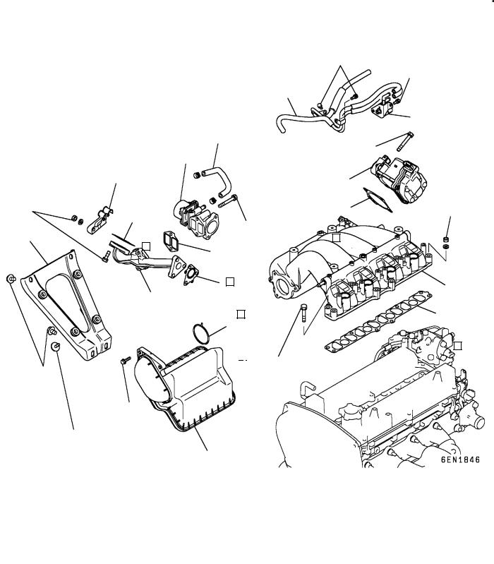
3. ALTERNATOR AND IGNITION SYSTEM
REMOVAL AND INSTALLATION <CARBURETOR>
8
6
12 Nm
25 Nm |
7 |
|
10


4
10 Nm |
3 |
9 |
|
||
|
|
44 Nm |
22 Nm |
24 Nm |
2 |
|
|
|
|
9 Nm |
5 |
25 Nm
1
Removal steps
1.Drive belt
2.Water pump pulley
3.Alternator brace
4.Alternator
5.Crankshaft pulley
6.Spark plug cable
7.Spark plug
8.High tension cable
"BA 9. Distributor assembly 10. O-ring
EMitsubishi Motors Corporation |
Dec. 1996 |
PWEE9616 |
11A-3-2 4G6 ENGINE (E - W) - Alternator and Ignition System
REMOVAL AND INSTALLATION <MULTIPOINT FUEL INJECTION>
10 Nm
7
10 Nm
6
|
|
9 |
10 |
|
25 Nm |
8 |
|
|
|
|
|
|
||
|
|
|
||
|
|
|
|
|
11
4
22 Nm
10 Nm
3
14 Nm
44 Nm
r
22 Nm |
24 Nm |
2 |
|
|
|
|
9 Nm |
5 |
25 Nm
1
Removal steps |
|
|
|
1. |
Drive belt |
7. |
Ignition coil assembly |
2. |
Water pump pulley |
8. |
Spark plug |
3. |
Alternator brace |
9. |
Camshaft position sensor |
4. |
Alternator |
"AA 10. |
Camshaft position sensing support |
5. |
Crankshaft pulley |
11. |
Camshaft position sensing cylinder |
6. |
Spark plug cable |
|
|
EMitsubishi Motors Corporation |
Dec. 1996 |
PWEE9616 |
4G6 ENGINE (E - W) - Alternator and Ignition System |
11A-3-3 |
REMOVAL AND INSTALLATION (GDI)
9.8 Nm
11
25 Nm
12
49 Nm
6
7
9.8 Nm
1
22 Nm |
8.8 Nm |
23 Nm |
4 |
5 |
|
|
||
|
|
|
||||
|
|
|
|
|
|
13 Nm |
8 |
|
|
|
|
|
|
|
9 |
|
|
2 |
||
49 Nm |
|
|
|
|
||
|
|
|
|
25 Nm |
|
3 |
|
|
|
|
|
||
|
|
|
|
|
|
|
|
|
|
|
10 |
|
|
|
|
|
|
49 Nm |
||
22 Nm
Removal steps |
|
|
|
1. |
Oil level gauge |
8. |
Idler pulley bracket |
2. |
Oil level gauge guide |
|
(Vehicle for Hong Kong) |
3. |
O-ring |
9. |
Idler pulley |
4. |
Drive belt |
|
(Vehicle for Hong Kong) |
5. |
Water pump pulley |
10. |
Crankshaft pulley |
6. |
Alternator |
11. |
Ignition coil |
7. |
Alternator brace |
12. |
Spark plug |
EMitsubishi Motors Corporation |
Aug. 1999 |
PWEE9616-B |
Revised |
11A-3-4 4G6 ENGINE (E - W) - Alternator and Ignition System
Stud bolt
INSTALLATION SERVICE POINTS
"AACAMSHAFT POSITION SENSOR SUPPORT
INSTALLATION
(1)Apply a 3 mm bead of form-in-place gasket (FIPG) to the area shown.
Specified sealant:
Mitsubishi Genuine Part No. MD970389 or equivalent
"BADISTRIBUTOR ASSEMBLY INSTALLATION
(1)Turn the crankshaft to bring No. 1 cylinder to the top dead center on compression stroke.
(2)Align the mating marks on the distributor housing with that of the coupling key.
(3)Install the distributor assembly on the engine while aligning the stud bolt used for securing the distributor with the slot in the mounting flange of the distributor.
EMitsubishi Motors Corporation |
Aug. 1998 |
PWEE9616-A |
Added |
4G6 ENGINE (E - W) - Intake Manifold (GDI) |
11A-3a-1 |
3a. INTAKE MANIFOLD (GDI)
REMOVAL AND INSTALLATION (SPACE WAGON)
8.8 Nm |
8.8 Nm |
2 |
11 Nm |
|
3 |
|
|
11Nm
8.8Nm 4 11 Nm
16 
12 |
|
|
|
|
|
|
|
|
|
|
14 |
|
11 |
5 |
|
|
|
||||
|
|
|
|
|
||||||
13 |
|
7 |
|
|
6 |
|||||
|
|
1 |
|
|
||||||
|
|
|
|
|
||||||
|
|
|
|
8.8 Nm |
||||||
|
|
23 Nm |
|
|
|
|
||||
23 Nm |
17 |
|
|
|
|
18 |
|
|
19 Nm |
|
|
|
|
|
|
|
|||||
15 |
|
|
|
|
|
|
|
|
|
|
|
10 |
|
|
|
|
|
|
|
||
11 Nm |
|
|
|
19 |
|
|
|
|||
|
|
|
|
|
|
|
|
|||
30 Nm |
|
|
|
|
19 Nm |
|
|
|
||
|
|
|
|
|
|
|
||||
|
|
|
|
|
|
|
|
|
|
|
9
8.8 Nm
30 Nm
8
Removal steps |
|
|
|
1. |
Vacuum pipe and hose |
"DA 7. |
Throttle body gasket |
|
(1999 model vehicles for Hong |
"CA 8. |
Intake manifold stay |
|
Kong) |
"BA 9. |
Air intake plenum resonator |
2. |
Solenoid valve (1999 model ve- |
10. |
Gasket |
|
hicles for Hong Kong) |
11. |
Water hose |
3. |
Vacuum pipe and hose |
12. |
EGR valve |
|
(Vehicles for Europe and 2000 |
13. |
Gasket |
|
model vehicles for Hong Kong) |
"AA 14. |
Hose clamp |
4. |
Solenoid valve |
"AA 15. |
EGR support |
|
(Vehicles for Europe and 2000 |
"AA 16. |
Gasket |
|
model vehicles for Hong Kong) |
17. |
Gasket |
5. |
Vacuum pipe |
18. |
Intake manifold |
6. |
Throttle body |
19. |
Gasket |
EMitsubishi Motors Corporation |
Aug. 1999 |
PWEE9616-B |
Revised |
11A-3a-2 4G6 ENGINE (E - W) - Intake Manifold (GDI)
REMOVAL AND INSTALLATION (GALANT)
|
|
|
|
|
|
|
|
8.8 Nm |
|
|
|
|
|
|
|
|
|
|
|
|
|
|
8.8 Nm |
||
|
|
|
|
|
|
1 |
|
|
|
|
|
|
|
|
|
|
|
|
|
|
|
|
2 |
|
|
|
8 |
|
|
|
|
|
11 Nm |
|
|
|
||
|
9 |
|
|
|
|
|
|
|
|
|||
|
|
|
|
|
|
|
|
|
|
|||
|
11 |
|
|
|
|
3 |
|
|
|
|||
|
|
|
|
|
|
|
|
|
||||
23 Nm |
13 |
|
|
|
|
|
|
|
4 |
19 Nm |
||
|
|
|
|
|
||||||||
|
|
|
|
|
|
|
|
|||||
|
|
|
|
|
|
|
|
|||||
|
|
|
|
|
|
|
|
|
|
|
|
|
5 |
|
|
|
|
|
23 Nm |
|
|
|
|||
|
|
|
|
|
|
|
|
|
|
|
|
|
|
10 |
|
|
|
|
|
|
|
|
|
||
|
|
|
|
|
|
|
|
|
|
|||
|
14 |
|
|
|
|
15 |
|
|||||
|
|
|
|
|
|
|||||||
|
|
|
|
|
|
|||||||
|
12 |
|
|
|
|
|
|
|
|
|
||
|
|
|
|
|
|
|
|
|
|
16 |
|
|
|
|
|
|
|
|
|
|
|
|
|
|
|
7 


19 Nm
30 Nm
11 Nm
8.8 Nm
6
Removal steps
1.Vacuum pipe and hose
2.Solenoid valve
3.Throttle body
"DA 4. Throttle body gasket "CA 5. Intake manifold stay
"BA 6. Air intake plenum resonator
7.Gasket
8.Water hose
9.EGR valve
10.Gasket
"AA 11. Hose clamp "AA 12. EGR support "AA 13. Gasket
14.Gasket
15.Intake manifold
16.Gasket
EMitsubishi Motors Corporation |
Aug. 1999 |
PWEE9616-B |
Revised |
4G6 ENGINE (E - W) - Intake Manifold (GDI) |
11A-3a-3 |
Intake manifold side
Cylinder head side
Hose clamp
Intake manifold stay
Air intake plenum resonator
Projection
INSTALLATION SERVICE POINTS
"AAEGR SUPPORT / HOSE CLAMP / GASKET
INSTALLATION
(1)Install the gasket, EGR support and hose clamp to the cylinder head in that order and tighten the fasteners temporarily.
(2)Install the EGR support assembly to the intake manifold with the gasket attached on the mating surface, and tighten the fasteners to the specified torque.
(3)Tighten the fasteners on the cylinder head side to the specified torque.
"BAAIR INTAKE PLENUM RESONATOR
INSTALLATION
(1)Install the mounting bolts on the throttle body side without fail.
"CAINTAKE MANIFOLD STAY INSTALLATION
(1)Tighten the fasteners to the specified torque after confirming that the intake manifold stay is in close contact with the air intake plenum resonator and the cylinder block.
"DATHROTTLE BODY GASKET INSTALLATION
(1) Position the projection as shown in the illustration.
EMitsubishi Motors Corporation |
Aug. 1999 |
PWEE9616-B |
Added |
4G6 ENGINE (E - W) - Timing Belt |
11A-4-1 |
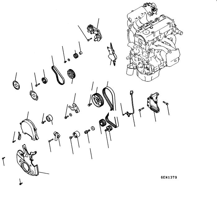
4. TIMING BELT
REMOVAL AND INSTALLATION (SOHC)
45 Nm
18
45 Nm
17
16
14 |
15 |
18 Nm |
|
|
13 |
19
7
22 Nm
1 48 Nm
6
14 Nm
8 9
23 Nm |
35 Nm |
|
11 Nm
9 Nm |
2 |
|
Removal steps
1.Timing belt front upper cover
2.Timing belt front lower cover
3.Power steering bracket
4.Crankshaft position sensor (Multipoint fuel injection)
AA" "KA 5. Timing belt "JA 6. Tensioner pulley
7. Tensioner arm "IA 8. Auto tensioner
9. Idler pulley
AC" "HA 10. Oil pump sprocket AD" "GA 11. Crankshaft bolt
20
23
88 Nm 5
22
21
9 Nm
49 Nm |
49 Nm |
|
3
4
12
11 10
54 Nm
118 Nm
AE" |
12. |
Crankshaft sprocket |
|
13. |
Flange (Multipoint fuel injection) |
|
14. |
Flange (Carburetor) |
|
15. |
Tensioner “B” |
AF" "FA 16. |
Timing belt “B” |
|
AG" "EA 17. |
Counterbalance shaft sprocket |
|
|
"DA 18. |
Spacer |
AH" |
19. |
Crankshaft sprocket “B” |
|
"CA 20. |
Engine support bracket |
AI" |
"AA 21. |
Camshaft sprocket bolt |
|
22. |
Camshaft sprocket |
|
23. |
Timing belt rear cover |
EMitsubishi Motors Corporation |
Aug. 1999 |
PWEE9616-B |
Revised |

11A-4-2 |
4G6 ENGINE (E - W) - Timing Belt |
|||||||
REMOVAL AND INSTALLATION (GDI) |
|
|
|
|
|
|
||
|
|
|
|
|
|
21 |
|
|
|
|
|
22 |
|
|
25 |
|
|
|
1 |
|
|
|
3.4 Nm |
|||
|
|
|
|
|
|
|
|
|
|
6 |
|
|
|
|
|
|
|
|
48 Nm |
|
7 |
|
|
|
|
|
|
|
|
23 |
|
26 |
|
|
|
|
|
|
|
|
24 |
|
|
|
|
|
|
|
|||||
|
|
|
23 Nm |
27 |
|
|
||
|
|
|
|
|
||||
|
|
|
|
|
|
|||
|
|
8 |
|
|
|
|
|
|
2 |
23 Nm |
31 |
|
|
|
|||
|
|
|
|
|
|
|||
|
13 |
11 Nm |
|
|
|
|||
11 Nm |
12 |
|
|
|
|
|
|
|
|
|
|
|
|
|
|
|
|
|
118 Nm |
|
|
|
|
|
|
|
9 Nm |
49 Nm |
|
11 Nm |
32 |
|
|
||
|
|
|
|
|
|
|||
|
|
|
|
|
|
|
|
|
|
5 |
|
|
|
|
|
|
|
30 |
18 |
|
|
|
|
3 |
|
|
45 Nm |
|
|
|
|
|
|||
|
17 |
|
|
|
|
4 |
|
|
88 Nm |
18 Nm |
|
28 |
|
|
|
||
|
|
|
|
|
|
|||
29 |
15 |
|
|
|
10 |
|
33 |
48 Nm 20
19
16
14
9
11
54 Nm
Removal steps
8.8 Nm
49 Nm
|
1. |
Front upper cover |
|
"DA 18. |
Spacer |
|
2. |
Front lower cover |
AH" |
19. |
Crankshaft sprocket B |
|
3. |
Power steering pump bracket stay |
|
20. |
Crankshaft key |
|
4. |
Power steering bracket |
|
21. |
Breather hose |
AB" "LA 5. |
Timing belt |
|
22. |
PCV hose |
|
"JA |
6. |
Tensioner pulley |
|
23. |
PCV valve |
|
7. |
Tensioner arm |
|
24. |
PCV valve gasket |
"IA |
8. |
Auto tensioner |
|
25. |
Oil filler cap |
|
9. |
Idle pulley |
|
26. |
Rocker cover |
|
10. |
Crankshaft position sensor |
|
27. |
Rocker cover gasket |
AC" "HA 11. |
Oil pump sprocket |
|
"CA 28. |
Engine support bracket |
|
AD" "GA 12. |
Crankshaft bolt |
AJ" "BA 29. |
Camshaft sprocket bolt |
||
AE" |
13. |
Crankshaft sprocket |
|
30. |
Camshaft sprocket |
|
14. |
Flange |
|
31. |
Timing belt rear right cover |
|
15. |
Tensioner B |
|
32. |
Timing belt rear left upper cover |
AF" "FA 16. |
Timing belt B |
|
33. |
Timing belt rear left lower cover |
|
AG" "EA 17. |
Counterbalance shaft sprocket |
|
|
|
|
EMitsubishi Motors Corporation |
Aug. 1999 |
PWEE9616-B |
Revised |
4G6 ENGINE (E - W) - Timing Belt |
11A-4-3 |
Timing mark
REMOVAL SERVICE POINTS
AA"TIMING BELT REMOVAL
(1)Mark belt running direction for reinstallation. NOTE
(1)Water or oil on the belt shorten its life drastically, so the removed timing belt, sprocket, and tensioner must be free from oil and water. These parts should not be washed. Replace parts if seriously contaminated.
(2)If there is oil or water on each part, check front case oil seals, camshaft oil seal and water pump for leaks.
AB"TIMING BELT REMOVAL
(1)If the timing belt is to be reused, chalk an arrow mark on the back surface of the belt so that the belt can be reinstalled in the same direction.
(2)Place the exhaust camshaft sprocket in a position where the timing mark for No. 1 cylinder is positioned about one tooth before the top dead center of the compression stroke.
Caution
D The camshaft sprocket on the exhaust side can turn very easily because of the valve spring tension. Use care not to allow your fingers to get caught by the sprocket.
(3)Loosen the lock nut of the tensioner pulley, then remove the timing belt.
AC"OIL PUMP SPROCKET REMOVAL
(1)Remove the plug on the left side of cylinder block.
(2)Insert a screwdriver (shank diameter 8 mm) to block the counterbalance shaft.
(3)Remove the nut.
(4)Remove the oil pump sprocket.
EMitsubishi Motors Corporation |
Aug. 1998 |
PWEE9616-A |
Revised |
11A-4-4 |
4G6 ENGINE (E - W) - Timing Belt |
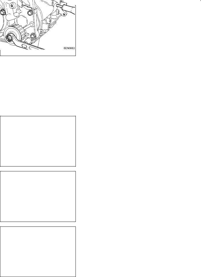
AD"CRANKSHAFT BOLT LOOSENING
(1)Hold the drive plate with the special tool as shown.
(2)Remove the crankshaft bolt.
6EN1322
MD998785
AE" CRANKSHAFT SPROCKET REMOVAL
(1)If it is difficult to remove the sprocket, use the special tool.
AF" TIMING BELT “B” REMOVAL
(1)Make a mark on the back of the timing belt indicating the direction of rotation so it may be reassembled in the same direction if it is to be reused.
NOTE
(1)Water or oil on the belt shortens its life drastically, so the removed timing belt, sprocket, and tensioner must be free from oil and water. These parts should not be washed. Replace parts if seriously contaminated.
(2)If there is oil or water on each part check front case oil seals, camshaft oil seal and water pump for leaks.
AG"COUNTERBALANCE SHAFT SPROCKET
REMOVAL
(1)Set the special tool as shown to prevent the counterbalance shaft sprocket from turning together.
(2)Loosen the bolt and remove the sprocket.
EMitsubishi Motors Corporation |
Aug. 1998 |
PWEE9616-A |
Revised |
4G6 ENGINE (E - W) - Timing Belt |
11A-4-5 |
AH"CRANKSHAFT SPROCKET “B” REMOVAL
(1)If it is difficult to remove the sprocket, use the special tool.
AI" CAMSHAFT SPROCKET BOLT LOOSENING
(1)Using the special tools shown in the illustration, lock the camshaft sprocket in position.
(2)Loosen the camshaft bolt.
AJ" CAMSHAFT SPROCKET BOLT LOOSENING
(1)Use a wrench to hold the hexagonal part of the camshaft, and then remove the camshaft sprocket mounting bolt.
INSTALLATION SERVICE POINTS
"AACAMSHAFT SPROCKET BOLT TIGHTENING
(1)Using the special tools shown in the illustration, lock the camshaft sprocket in position.
(2)Tighten the camshaft sprocket bolt to the specified torque.
"BACAMSHAFT SPROCKET BOLT TIGHTENING
(1)Using a wrench, hold the camshaft at its hexagon and tighten the bolt to the specification.
EMitsubishi Motors Corporation |
Aug. 1998 |
PWEE9616-A |
Revised |
Loading...