


A-100TMU A,-80TMU-PUHY Handbook Service
AIR CONDITIONERS CITY MULTI Series Y
Models PUHY-80TMU-A, 100TMU-A
Service Handbook
Safety precautions
Before installation and electric work
sBefore installing the unit, make sure you read all the “Safety precautions”.
sThe “Safety precautions” provide very important points regarding safety. Make sure you follow them.
sThis equipment may have an adverse effect on equipment on the same electrical supply system.
sPlease report to or take consent by the supply authority before connection to the system.
Symbols used in the text
 Warning:
Describes precautions that should be observed to prevent danger of injury or death to the user.
 Caution:
Describes precautions that should be observed to prevent damage to the unit.
Symbols used in the illustrations
: Indicates an action that must be avoided.
: Indicates that important instructions must be followed.
: Indicates a part which must be grounded.
: Indicates that caution should be taken with rotating parts.
(This symbol is displayed on the main unit label.) <Color: Yellow>
: Indicates that the main switch must be turned off before servicing. (This symbol is displayed on the main unit label.) <Color: Blue>
 : Beware of electric shock (This symbol is displayed on the main unit label.) <Color: Yellow>
 : Beware of hot surface (This symbol is displayed on the main unit label.) <Color: Yellow>
 ELV : Please pay attention to electric shock because this is not Safety Extra Low-Voltage (SELV) circuit.
And at servicing, please shut down the power supply for both Indoor Unit and Outdoor Unit .
 Warning:
Carefully read the labels affixed to the main unit.
 Warning:
•Ask the dealer or an authorized technician to install the air conditioner.
-Improper installation by the user may result in water leakage, electric shock, or fire.
•Install the air unit at a place that can withstand its weight.
-Inadequate strength may cause the unit to fall down, resulting in injuries.
•Use the specified cables for wiring. Make the connections securely so that the outside force of the cable is not applied to the terminals.
-Inadequate connection and fastening may generate heat and cause a fire.
•Prepare for typhoons and other strong winds and earthquakes and install the unit at the specified place.
-Improper installation may cause the unit to topple and result in injury.
•Always use an air cleaner, humidifier, electric heater, and other accessories specified by Mitsubishi Electric.
-Ask an authorized technician to install the accessories. Improper installation by the user may result in water leakage, electric shock, or fire.
•Never repair the unit. If the air conditioner must be repaired, consult the dealer.
-If the unit is repaired improperly, water leakage, electric shock, or fire may result.
•Do not touch the heat exchanger fins.
-Improper handling may result in injury.
•If refrigerant gas leaks during installation work, ventilate the room.
-If the refrigerant gas comes into contact with a flame, poisonous gases will be released.
•Install the air conditioner according to this Installation Manual.
-If the unit is installed improperly, water leakage, electric shock, or fire may result.
•Have all electric work done by a licensed electrician according to “Electric Facility Engineering Standard” and “Interior Wire Regulations”and the instructions given in this manual and always use a special circuit.
-If the power source capacity is inadequate or electric work is performed improperly, electric shock and fire may result.
•Securely install the cover of control box and the panel.
-If the cover and panel are not installed properly, dust or water may enter the outdoor unit and fire or electric shock may result.
•When installing and moving the air conditioner to another site, do not charge it with a refrigerant different from the refrigerant (R22) specified on the unit.
-If a different refrigerant or air is mixed with the original refrigerant, the refrigerant cycle may malfunction and the unit may be damaged.
•If the air conditioner is installed in a small room, measures must be taken to prevent the refrigerant concentration from exceeding the safety limit even if the refrigerant should leak.
-Consult the dealer regarding the appropriate measures to prevent the safety limit from being exceeded. Should the refrigerant leak and cause the safety limit to be exceeded, hazards due to lack of oxygen in the room could result.
•When moving and reinstalling the air conditioner, consult the dealer or an authorized technician.
-If the air conditioner is installed improperly, water leakage, electric shock, or fire may result.
•After completing installation work, make sure that refrigerant gas is not leaking.
-If the refrigerant gas leaks and is exposed to a fan heater, stove, oven, or other heat source, it may generate noxious gases.
•Do not reconstruct or change the settings of the protection devices.
-If the pressure switch, thermal switch, or other protection device is shorted and operated forcibly, or parts other than those specified by Mitsubishi Electric are used, fire or explosion may result.
Contents |
|
|
1 COMPONENT OF EQUIPMENT ............................................... |
1 |
|
[1] |
Appearance of Components............................................ |
1 |
[2] Refirigerant Circuit Diagram and Thermal Sensor........... |
6 |
|
[3] PUHY-80, 100TMU-A ELECTRICAL WIRING |
|
|
|
DIAGRAM ....................................................................... |
7 |
[4] |
Standard operation data .................................................. |
9 |
[5] Function of dip SW and rotary SW ................................ |
11 |
|
2 TEST RUN ............................................................................... 15 |
||
[1] |
Before Test Run ............................................................ |
15 |
[2] |
Test Run Method ........................................................... |
19 |
3 GROUPING REGISTRATION OF INDOOR UNITS WITH |
|
|
M-NET REMOTE CONTROLLER ........................................... |
20 |
|
4 CONTROL ............................................................................... 26 |
||
[1] Control of Outdoor Unit ................................................. |
26 |
|
[2] |
Operation Flow Chart .................................................... |
31 |
[3] List of Major Component Functions ............................... 36 |
||
[4] Resistance of Temperature Sensor............................... |
38 |
|
5 REFRIGERANT AMOUNT ADJUSTMENT .............................. 39 |
||
[1] Refrigerant Amount and Operating Characteristics....... |
39 |
|
[2] Adjustment and Judgement of Refrigerant Amount....... |
39 |
|
6 TROUBLESHOOTING............................................................. |
44 |
|
[1] |
Principal Parts................................................................ 44 |
|
[2] Self-diagnosis and Countermeasures Depending on the |
||
|
Check Code Displayed .................................................. |
62 |
[3] |
LED Monitor Display ...................................................... |
83 |
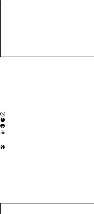
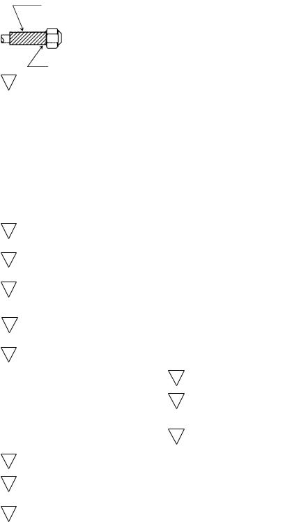
Propeller fan
Fan motor
- 1 -
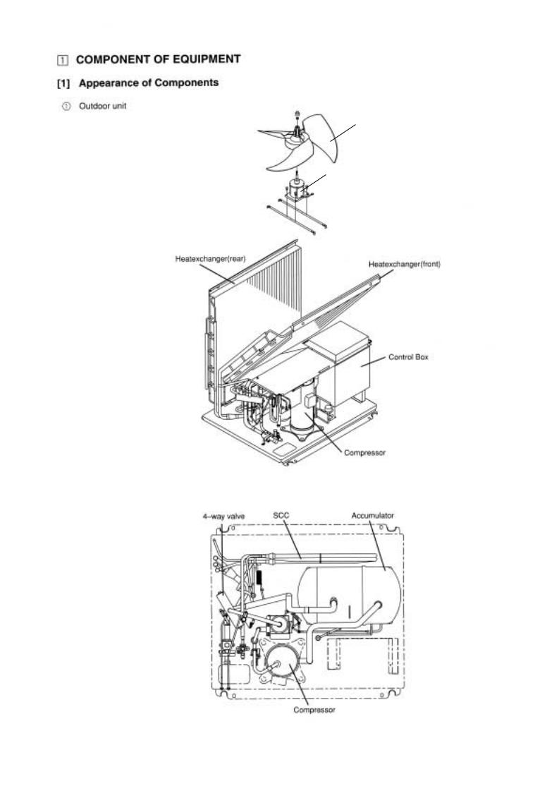
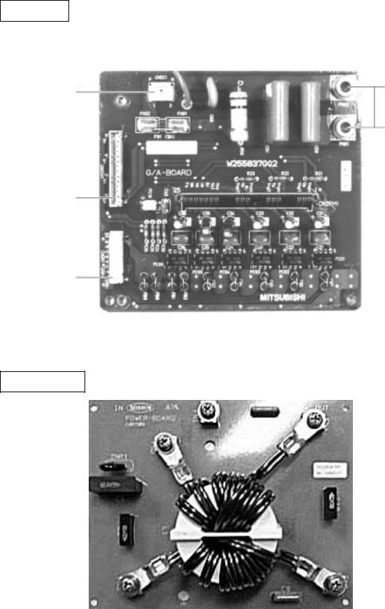
Rear Controller Box
INV board
MAIN board
Choke coil(L2)
Interrigent Power Module(IPM)
Magnetic contactor(52C)
Capacitor (C1)(Smoothing capacitor)
Gate Amplifier board(G/A board)
Diode stack(DS)
Power board
Terminal block(TB7)Transmission
Terminal |
Terminal |
block (TB1) |
block (TB3) |
Power source |
Transmission |
- 2 -

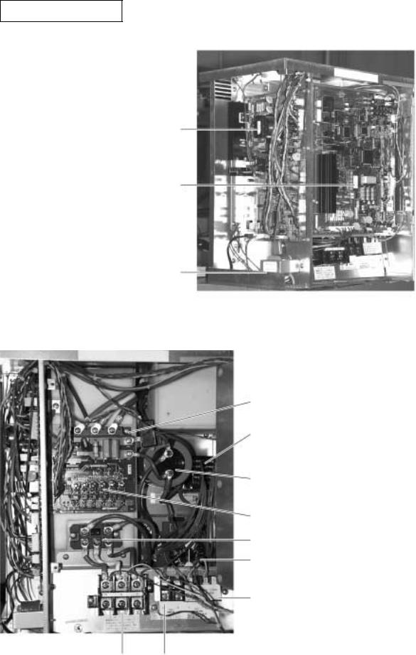
MAIN board
CNS1 M-NET
Transmission (DC30V)
CNS2 M-NET Transmission (Centralized control) (DC30V)
 CN40 M-NET
Transmission
Power supply
CNVCC3 Power source for contorl 1-2 DC30 V 1-3 DC30 V 4-6 DC12 V 5-6 DC5 V
CN51 Indication distance 3-4 Compressor ON/
Off 3-4 trouble
LD1
Service LED
CNRS53
Serial transmission to
INV board
 CN3D
CN3D
SW1,2,3,4 Dip Switch
 CN3S
CN3S
CNFAN1 control for MF1
CN20 CNAC3 power
source
- 3 -
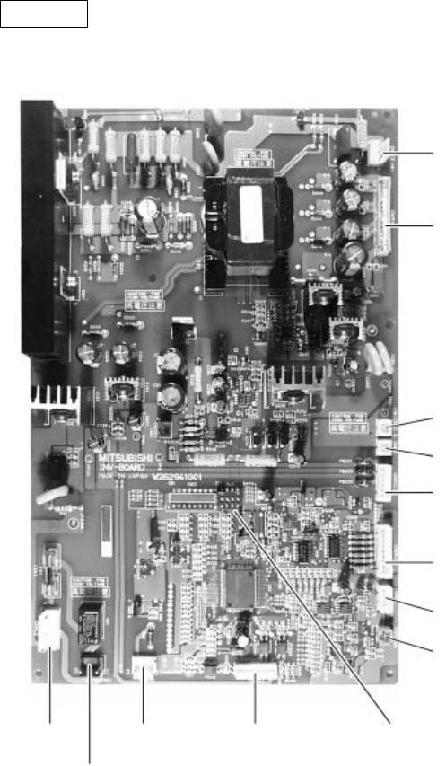
INV board
CNAC2 |
CN52C |
CNRS2 |
Power source |
Control for |
Serial transmission |
1 L2 |
52C |
to MAIN board |
5 N |
|
|
CNFAN |
|
|
Control for
MF1
CNDC2
1-3 DC310 V
CN15V2
Power supply IPM control 1-2 DC15 V
5-6 DC15 V
9-0 DC15 V
C-D DC15 V
CNVCC4
CNL2
Choke coil
CNVCC2 power supply
CNDR2 IPM control signal
CNCT
CNTH
SW1
- 4 -
G/A board
CNDC1
1 - 3 DC310V
DC310V
CN15V1 Power Supply IPM control 1 - 2 DC15V 5 - 6 DC15V 9 - 0 DC15V C - D DC15V
CNDR1
IPM control signal
Power board
- 5 -
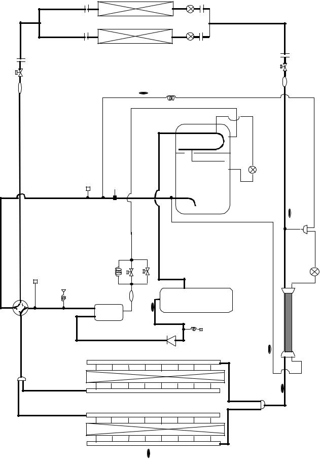
[2] Refirigerant Circuit Diagram and Thermal Sensor
1 PUHY-80TMU-A, 100TMU-A
BV1 |
Indoor |
Unit |
|
|
BV2 |
ST1 |
|
|
TH2 |
CP2 |
ST2 |
|
|
|
safety valve |
|
|
Accumulator |
SA |
|
|
|
|
CJ2 |
High pressure |
|
|
MA |
|
SLEV |
|
|
|
|
|
|
|
|
|
|
TH7 |
|
|
|
|
|
|
|
|
|
ST7 |
CJ1 |
63HS |
CP1 |
SV1 |
|
SV2 |
|
Comp |
|
LEV1 |
|
|
O/S |
ST6 |
TH1 |
CV1 |
|
63H |
SCC |
|
|
|
|
|
|
|
|
|
|
TH8 |
|
|
HEXF |
|
|
|
|
|
|
TH5 |
TH6
HEXB
- 6 -
- 7 -
TB1
L1
Power source |
L2 |
3~208~230V |
|
60Hz |
L3 |
Connect to indoor and remote controller
CH1
SV1
21
S4
SV 2
MF
63H
GR 
Ground
CN20
(7P)
DSA
3 CN32
2 (3P)
1
6 CN33
5 (6P)
4
3
2
1
6 CN34
5 (6P)
4 Red
3
2
1
5
4CNFAN1
32(5P)
1Red
3 CN38
2 (3P)
1 Green
Green |
Black |
White |
GL3 L2
13 5
F2
6.3A
X 0 1
X02
X04
X05
Detection
Circuit
|
|
|
|
|
|
|
|
|
|
|
|
MC |
|
|
|
|
|
|
|
|
|
Noise filter board |
|
|
|
|
U V W |
|
|
||
|
|
|
|
|
|
|
|
|
|
Red |
White |
Black |
|
||
|
|
|
|
|
|
(POWER-BOARD) |
|
|
|
IPM |
|
||||
|
DS(Diode stack) |
|
|
R 1 |
|
|
|
|
|
|
|
|
|||
|
|
|
|
FN3 |
|
|
|
|
U |
V |
W |
|
|||
|
Red |
|
FN1 |
|
|
FN6 |
|
Red |
P |
|
|
||||
|
|
|
|
|
|
Gate amp board |
|
|
|||||||
|
+ |
|
|
|
|
|
|
|
|
|
|
CNE 1 |
|
||
|
|
|
|
|
|
|
|
DCL + |
|
|
F01 |
(G/A-BOARD) |
|
||
|
Black |
|
|
|
52C |
FN2 |
FN4 |
C 1 |
Black |
N |
3.15A |
|
|
(2P) 2 |
|
|
|
|
|
|
|
|
|
|
|
|
|||||
|
- |
|
|
|
|
|
|
|
|
|
|
CNDR1 |
CN15V1 |
|
|
|
|
|
|
|
|
|
|
|
|
|
|
|
|||
|
|
|
|
|
|
|
|
1 2 |
3 4 |
Yellow |
|
(9P) |
(14P) |
Ground |
|
|
|
|
|
|
|
|
|
|
|
CNDC1 1 2 3 |
123456789 |
1234567891011121314 |
|||
Red |
T B 3 |
|
T B 7 |
|
|
|
|
DCCT |
|
(3P) |
|
|
|
|
|
A |
B |
A |
B Shield |
|
|
|
|
|
|
|
|
|
|
||
L1 |
|
|
|
|
|
|
|
|
|
|
|
|
|
|
|
7
1 2 3 4
F1
6.3A CN40
ZNR1~4
(4P)
1 2 3 4
CN41
(4P)
1 |
2 |
1 |
2 |
3 |
|
|
|
CNS1 |
|
CNS2 |
|
|
|||
(2P) |
|
(3P) |
|
|
|||
|
|
Control circuit board |
|
|
|||
|
|
(MAIN-BOARD) |
|
1 |
|||
|
|
|
|
|
CNRS3 |
||
|
|
|
|
|
2 |
||
|
|
|
|
|
(7P) |
3 |
|
|
|
|
|
|
|
4 |
|
|
|
|
|
|
|
5 |
|
|
|
|
|
|
|
6 |
|
|
|
|
|
|
|
7 |
|
|
LD1 |
|
|
|
CNVCC3 |
1 |
|
|
|
|
|
|
2 |
||
|
|
|
|
|
(6P) |
3 |
|
|
|
|
|
|
|
4 |
|
|
|
|
|
|
|
5 |
|
|
|
|
|
|
|
6 |
|
OFF ON OFF ON OFF ON OFF ON |
CNVCC5 1 |
||||||
1 |
1 |
1 |
|
1 |
(2P) |
2 |
|
|
|
|
|
|
CNAC3 |
1 |
|
|
|
|
|
|
(5P) |
2 |
|
|
|
|
|
|
3 |
||
|
|
|
|
|
|
4 |
|
|
|
|
|
|
|
5 |
|
10 |
10 |
10 |
|
10 |
CNLV1 |
1 |
|
|
|
|
|
|
(5P) |
2 |
|
SW4 |
SW3 |
SW2 |
SW1 |
3 |
|||
Blue |
|||||||
4 |
|||||||
|
|
|
|
|
|
5 |
|
|
|
|
|
|
CNLV2 |
1 |
|
|
|
|
|
|
(5P) |
2 |
|
|
|
|
|
|
3 |
||
|
|
SWU2 SWU1 |
Red |
4 |
|||
|
|
|
5 |
||||
Unit address setting switch
|
1 |
2 |
3 |
4 |
1 2 3 |
123456789 |
1234567891011121314 |
|
|
|
|
CNCT CNDC2 |
CNDR2 |
CN15V2 |
|||
52 |
1 |
(4P) |
(3P) |
(9P) |
(14P) |
|||
C |
2 |
|
CN52CYellow |
|
|
|||
|
3 |
|
(3P) |
|
|
|
||
|
|
1 |
CNRS2 |
|
|
|||
|
|
2 |
Power circuit board |
|||||
|
|
3 |
(7P) |
|
||||
|
|
4 |
|
|
|
(INV-BOARD) |
||
|
|
5 |
|
|
|
|
|
|
|
|
6 |
|
|
|
|
|
|
|
|
7 |
|
|
|
|
|
|
1
2 CNVCC2
3 (6P)
4
5
6
1CNVCC4
2(2P)
G |
G |
1 |
CNAC2 |
|
L3 |
L3 |
|
||
2 |
(5P) |
|
||
|
|
3 |
|
|
L1 |
L1 |
4 |
|
|
|
|
5 |
F01 |
X01 |
|
|
|
||
|
|
|
2A |
|
|
SLEV |
|
|
|
|
LEV1 |
Green |
CNL2 |
Red |
|
Red |
|
CNTH |
CN30V |
|
CNFAN |
||
|
|
(2P) |
(2P) |
(2P) |
|
(3P) |
|
|
1 2 |
1 2 |
1 2 |
1 2 |
3 |
5 |
Trouble |
|
|
|
|
|
4 |
Compressor ON/OFF |
THHS |
L2 |
R2 |
|
|
3 |
CN51 |
MF |
|
|||
2 |
|
|
|
1 |
|
|
1 |
(5P) |
|
|
|
|
|
|
|
|
|
12V |
3 |
|
Compressor ON/OFF |
|
|
|
|
|
2 |
|
Night mode |
Red |
|
|
|
|
1 |
CN3D |
|
|
|
|
|
|
|||
CN03 |
CN02 |
CN01 |
CNH |
3 |
(3P) |
|
|
(3P) |
(8P) |
(2P) |
(3P) |
|
2 |
|
Snow sensor |
1 2 3 |
1 2 3 4 5 6 7 8 |
1 2 |
1 2 3 |
1 |
CN3S |
||
|
|
||||||
|
|
|
|
|
|
(3P) |
|
|
|
|
Black White |
Red |
|
Red |
SW3-10 are OFF for Model 80. |
|
|
|
|
|
|||
|
|
|
|
|
|
|
|
|
|
|
3 2 |
1 |
|
|
and ON for Model 100. |
TH6 |
TH5TH8TH7TH2 |
TH1 |
|
|
|
||
|
63HS |
|
|
|
|||
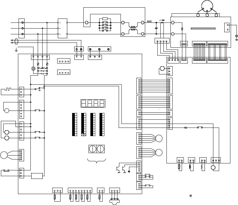
DIAGRAM WIRING ELECTRICAL A-100TMU 80,-PUHY [3]
- 8 -
Symbol
D S
I P M
D C L
D C C T
R 1
R 2
Z N R 1 ~ 4 C 1
5 2 C
M C
Name
Diode stack
Intelligent Power Module
DC reactor
(Power factor improvement)
Current Sensor
Resistor rush current protect
Resistor power regulation
Varistor
Capacitor Smoothing
Magnetic contactor (Inverter main circuit)
Motor Compressor
Symbol
M F
M F 1 D S A C H 1 2 1 S 4
S V 1 , S V 2
6 3 H T H 1
T H 2
T H 5
Name |
Symbol |
Name |
|
Motor Fan Heat exchanger |
T H 6 |
Thermistor OA temp.detect |
|
Motor Fan Radiator panel |
T H 7 |
liquid outlet temp. |
|
Surge absorber |
detect at Sub-cool coil |
||
|
|||
Crankcase heater (Compressor) |
T H 8 |
bypass outlet temp. |
|
4-way valve |
detect at Sub-cool coil |
||
|
|||
Solenoid valve |
T H H S |
Rediator panel temp.detect |
|
(Discharge-suction bypass) |
6 3 H S |
High pressure sensor |
|
High pressure switch |
S L E V |
Electronic expansion valve |
|
Thermistor discharge pipe temp.detect |
(Oil return) |
||
|
|||
saturation |
L E V 1 |
Electronic expansion valve |
|
evapo.temp.detect |
(Sub-cool coil bypass) |
||
|
|||
pipe temp.detect |
L 2 |
Choke coil(Transmission) |
Symbol
L D 1
S W 1
S W 2 ~4
S W U 1 ~ 2 T B 1
T B 3
T B 7
GR
Nam e
Luminous diode
Switch display selection self-diagnosis Switch function selection
Switch unit address set Terminal block power source Terminal block transmisson Terminal block transmisson centralized control
Ground terminal
<Operation of self-diagnosis switch (SW1) and LED display> |
|
<LED display> |
||||||||||||||
|
|
|
|
|
|
|
|
|
Display |
Display at LED lighting (blinking) Remarks SW1 operation |
|
LD1 |
||||
|
|
|
|
|
|
|
|
|
|
|
||||||
|
|
|
|
|
|
|
|
|
|
FLAG1 FLAG2 |
FLAG3 FLAG4 |
FLAG5 FLAG6 FLAG7 |
FLAG8 |
|
||
|
|
|
|
|
|
|
|
|
Relay output |
During |
Crankcase |
21S4 |
SV1 |
SV2 |
Always |
FLAG8 always lights at |
ON : 1 |
|
|
|
|
|
|
|
|
display |
compressor |
||||||
|
|
|
|
|
|
|
|
heater |
lighting |
|||||||
OFF : 0 |
|
|
|
|
|
|
|
|
(Lighting) |
run |
|
|
|
|
|
microcomputer power ON |
1 |
2 |
3 |
4 |
5 |
6 |
7 |
8 |
9 |
10 |
|
0000~9999 |
|
|
|
FLAG8 |
|
|
|
|
|
|
|
|
|
|
Check display |
|
|
|
|
|||
(at factory shipment) |
(Blinking) |
|
Display the address and error codes by turns |
|
FLAG7 |
|||||||||||
|
|
|
|
|
|
|
|
|
|
|
|
|||||
FLAG6
FLAG5
FLAG4
FLAG3
FLAG2
FLAG1
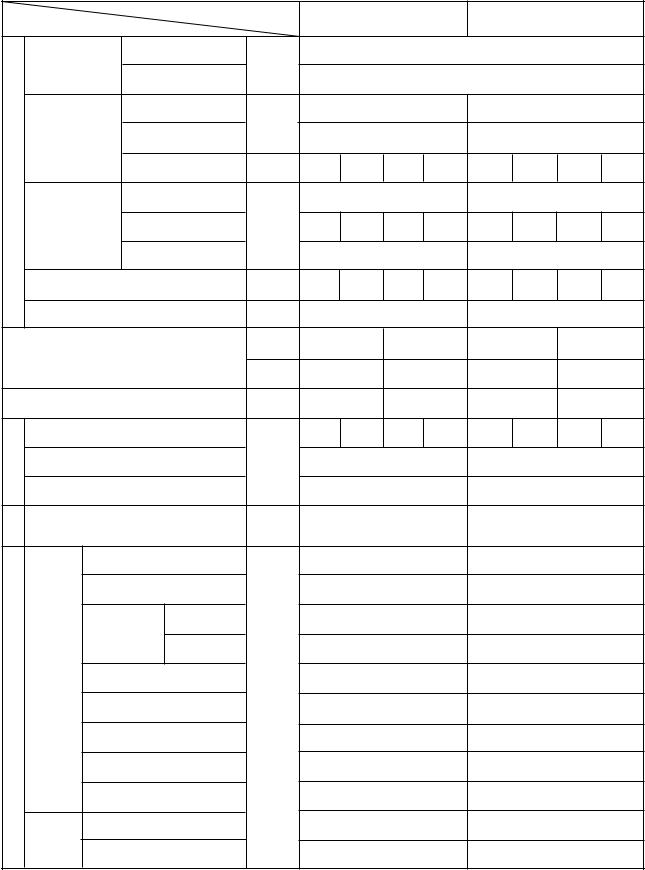
[4]Standard operation data
1 Cooling operation
|
Items |
Outdoor units |
PUHY-80TMU-A |
|
PUHY-100TMU-A |
|
|||||
|
|
|
|
|
|
|
|
|
|
|
|
|
|
Indoor |
|
|
|
26.7° C(80° F)/19.4° C(67° F) |
|
|
|||
|
Ambient temp. |
DB/WB |
|
|
|
|
|
|
|
|
|
|
|
|
|
|
35° C(95° F) |
|
|
|
|||
|
|
Outdoor |
|
|
|
|
|
|
|
||
|
|
Quantity |
Set |
|
4 |
|
|
|
4 |
|
|
|
|
|
|
|
|
|
|
|
|
|
|
|
Indoor unit |
Quantity in operation |
|
|
4 |
|
|
|
4 |
|
|
Condition |
|
Model |
– |
24 |
24 |
20 |
10 |
48 |
16 |
24 |
10 |
|
Main pipe |
|
|
5(16.4) |
|
|
5(16.4) |
|
|||
|
|
|
|
|
|
|
|||||
|
Piping |
Branch pipe |
m |
5(16.4) |
5(16.4) |
5(16.4) |
5(16.4) |
5(16.4) |
5(16.4) |
5(16.4) |
5(16.4) |
|
(Ft) |
||||||||||
|
|
|
|
|
|
|
|
|
|
|
|
|
|
Total piping length |
|
|
25(82) |
|
|
25(82) |
|
||
|
Indoor unit fan notch |
– |
Hi |
Hi |
Hi |
Hi |
Hi |
Hi |
Hi |
Hi |
|
|
Refrigerant volume |
kg(oz) |
|
10.2(360) |
|
|
12.5(441) |
|
|||
Compressor volts/Frequency |
V |
208 |
230 |
208 |
230 |
||||||
|
|
|
|
|
|
|
|
|
|||
|
|
|
V/Hz |
134/76 |
134/76 |
171/98 |
171/98 |
||||
Outdoor unit |
|
A |
27.4 |
24.8 |
35.2 |
31.8 |
|||||
opening |
Indoor unit |
|
|
440 |
440 |
380 |
300 |
450 |
320 |
440 |
300 |
SC (LEV1) |
Pulse |
|
75 |
|
|
|
81 |
|
|
||
LEV |
Oil return (SLEV) |
|
|
111 |
|
|
157 |
|
|||
Pressure |
High pressure/Low pressure |
MPa(psi) |
|
2.00/0.50 |
|
|
1.99/0.46 |
|
|||
(after O/S) |
(before MA) |
|
(290/72) |
|
|
(288/67) |
|
||||
|
|
|
|
|
|||||||
|
|
|
|
|
|
|
|
|
|
|
|
|
|
Discharge (TH1) |
|
|
85(185) |
|
|
95(203) |
|
||
|
|
Heat exchanger outlet (TH5) |
|
|
40(104) |
|
|
42(108) |
|
||
|
|
Inlet |
|
|
7(45) |
|
|
5(41) |
|
||
|
|
Accumulator |
|
|
|
|
|
|
|
|
|
temperature |
|
Outlet |
|
|
9(48) |
|
|
7(45) |
|
||
Outdoor |
Suction (Comp) |
|
|
7(45) |
|
|
10(50) |
|
|||
unit |
|
|
|
|
|
||||||
low pressure saturation |
° C |
|
|
|
|
|
|
|
|
||
|
|
6(43) |
|
|
4(39) |
|
|||||
|
temperature (TH2) |
(° F) |
|
|
|
|
|||||
|
|
|
|
|
|
|
|
|
|||
Sectional |
|
|
|
|
|
|
|
|
|
||
|
Shell bottom (Comp) |
|
|
60(140) |
|
|
60(140) |
|
|||
|
SCC outlet (TH7) |
|
|
27(81) |
|
|
27(81) |
|
|||
|
|
|
|
|
|
|
|||||
|
|
Bypass outlet (TH8) |
|
|
8(46) |
|
|
6(43) |
|
||
|
Indoor |
LEV inlet |
|
|
26(79) |
|
|
26(79) |
|
||
|
|
|
|
|
|
|
|
|
|
|
|
|
unit |
Heat exchanger outlet |
|
|
10(50) |
|
|
10(50) |
|
||
|
|
|
|
|
|
|
|||||
|
|
|
|
- 9 - |
|
|
|
|
|
|
|
2 Heating operation
|
|
Items |
|
|
Outdoor units |
||||
|
|
|
|
|
|
|
|||
|
|
|
|
|
|
Indoor |
|
|
|
|
|
|
|
|
|
|
|
||
|
|
Ambient temp. |
|
|
|
DB/WB |
|||
|
|
|
|
|
|||||
|
|
|
|
|
|
||||
|
|
|
|
|
|
Outdoor |
|
|
|
|
|
|
|
|
|
Quantity |
|
Set |
|
|
|
|
|
|
|
|
|
|
|
Condition |
|
Indoor unit |
|
Quantity in operation |
|||||
|
|
|
|
||||||
|
|
|
|
|
Model |
|
– |
||
|
|
|
|
|
|
|
|||
|
|
|
|
|
|
Main pipe |
|
|
|
|
|
Piping |
|
|
|
|
m |
||
|
|
|
Branch pipe |
|
|||||
|
|
|
|
|
|
|
|
|
|
|
|
|
|
|
|
Total piping length |
|
|
|
|
|
|
|
|
|
|
|
– |
|
|
|
Indoor unit fan notch |
|
||||||
|
|
Refrigerant volume |
|
kg |
|||||
|
|
|
|
|
|
|
|
|
V |
Compressor volts/Frequency |
|
||||||||
|
|
||||||||
|
|
|
|
|
|
|
|
|
V/Hz |
Outdoor unit |
|
|
|
|
A |
||||
LEVopening |
|
Indoor unit |
|
|
|
|
|
||
|
|
|
|
|
|
||||
|
|
|
|
|
|
|
Pulse |
||
|
Oil return (SLEV) |
|
|||||||
|
|
SC (LEV1) |
|
||||||
Pressure |
|
High pressure/Low pressure |
|
MPa(psi) |
|||||
|
|
|
|||||||
|
|
(after O/S) |
(before MA) |
|
|||||
|
|
|
|
||||||
|
|
|
|
|
Discharge (TH1) |
|
|
||
|
|
|
|
|
|
|
|||
|
|
|
|
|
|
|
|
|
|
|
|
|
|
|
Heat exchanger inlet (TH5) |
|
|
||
|
|
|
|
|
|
|
|
|
|
temperature |
|
|
|
|
Suction (Comp) |
Inlet |
|
° C |
|
|
|
|
|
|
|
||||
|
|
Outdoor |
|
Accumulator |
|
|
|
||
|
|
|
Outlet |
|
|
||||
|
|
|
|
|
|
|
|||
|
|
unit |
|
|
|
|
|
||
|
|
|
|
|
|
|
|
||
Sectional |
|
|
|
|
|
|
|
|
(° F) |
|
|
|
|
|
|
|
|
||
|
|
|
|
low pressure saturation |
|
|
|||
|
|
|
|
|
|
|
|||
|
|
|
|
|
temperature (TH2) |
|
|
||
|
|
|
|
|
Shell bottom (Comp) |
|
|
||
|
|
|
|
|
|
|
|
||
|
|
Indoor |
|
Heat exchanger inlet |
|
|
|||
|
|
|
|
|
|
|
|
||
|
|
unit |
|
|
|
|
|
|
|
|
|
|
LEV inlet |
|
|
||||
|
|
|
|
|
|
|
|||
|
|
|
|
|
|
|
|
|
|
|
PUHY-200TM-A |
|
|
|
PUHY-250TM-A |
|
|||||||
|
|
|
|
|
|
|
|
|
|
|
|
|
|
|
|
|
|
|
|
|
21.1° C(70° F) |
|
|
|
|
|
|
|
|
|
|
|
|
|
|
||||||
|
|
|
|
|
8.3° C(47° F)/6.1° C(43° F) |
|
|
||||||
|
4 |
|
|
|
|
4 |
|
|
|||||
|
|
|
|
|
|
|
|||||||
|
4 |
|
|
|
|
4 |
|
|
|||||
24 |
|
24 |
|
20 |
|
10 |
48 |
|
16 |
|
24 |
|
|
|
|
|
|
|
10 |
||||||||
|
|
|
|
|
|
|
|
|
|
|
|
||
|
5(16.4) |
|
|
|
5(16.4) |
|
|||||||
|
|
|
|
|
|
|
|
|
|
|
|
|
|
5(16.4) |
|
5(16.4) |
|
5(16.4) |
|
5(16.4) |
5(16.4) |
5(16.4) |
|
5(16.4) |
5(16.4) |
||
|
|
|
|
|
|
|
|
|
|
|
|||
|
25(82) |
|
|
|
25(82) |
|
|||||||
|
|
|
|
|
|
|
|
|
|
|
|
||
Hi |
|
|
Hi |
|
Hi |
|
Hi |
Hi |
|
Hi |
|
Hi |
Hi |
|
|
|
|
|
|
|
|
|
|
|
|
||
|
10.2(360) |
|
|
|
12.5(441) |
|
|||||||
208 |
|
230 |
208 |
|
230 |
||||||||
|
|
||||||||||||
149/85 |
|
149/85 |
174/100 |
|
174/100 |
||||||||
27.5 |
|
24.9 |
35.6 |
|
32.2 |
||||||||
510 |
|
|
510 |
|
450 |
|
300 |
350 |
|
|
510 |
|
|
|
|
|
|
|
380 |
|
300 |
||||||
|
|
|
|
|
|
|
|
|
|
|
|
|
|
|
0 |
|
|
|
|
0 |
|
|
|||||
|
|
|
|
|
|
|
|
|
|||||
|
87 |
|
|
|
111 |
|
|||||||
|
1.72/0.36 |
|
|
|
1.72/0.36 |
|
|||||||
|
(249/52) |
|
|
|
(249/52) |
|
|||||||
|
80 |
|
|
|
|
85(185) |
|
||||||
|
|
|
|
|
|
|
|||||||
|
6(46) |
|
|
|
8(46) |
|
|||||||
|
|
|
|
|
|
|
|
|
|||||
|
|
|
–1(30) |
|
|
|
–2(28) |
|
|||||
|
|
|
|
|
|
|
|
|
|||||
|
|
|
–1(30) |
|
|
|
–2(28) |
|
|||||
|
|
|
|
|
|
|
|
|
|||||
|
|
|
–1(30) |
|
|
|
–2(28) |
|
|||||
|
|
|
|
|
|
|
|
|
|||||
|
|
|
–2(28) |
|
|
|
–2(28) |
|
|||||
|
|
|
|
|
|
|
|||||||
|
35(95) |
|
|
|
44(111) |
|
|||||||
|
|
|
|
|
|
|
|||||||
|
71(160) |
|
|
|
71(160) |
|
|||||||
|
|
|
|
|
|
|
|||||||
|
33(91) |
|
|
|
33(91) |
|
|||||||
|
|
|
|
|
|
|
|
|
|
|
|
|
|
- 10 -
[5]Function of dip SW and rotary SW
(1) Outdoor unit
Switch |
Function |
Function According to Switch Operation |
Switch Set Timing |
|||||
When Off |
When On |
When Off |
|
When On |
||||
|
|
|
|
|
||||
SWU |
1~2 |
Unit Address Setting |
Set on 00 or 51~100 with the dial switch. ( 2) |
Before power is turned on. |
||||
SW1 |
1~8 |
For self diagnosis/ |
LED Monitering Display |
During normal operation when |
||||
|
|
operation monitoring |
|
|
power is on. |
|
|
|
|
9~10 |
|
– |
– |
– |
Should be set on OFF. |
||
SW2 |
1 |
Centralized Control |
Centralized control not |
Centralized control |
Before power is turned on. |
|||
|
|
Switch |
|
connected. |
connected. |
|
|
|
|
2 |
Deletion of connection |
Storing of refrigeration |
Deletion of refrigeration |
Before power is turned on. |
|||
|
|
information. |
system connection |
system connection |
|
|
|
|
|
|
|
|
information. |
information. |
|
|
|
|
3 |
Deletion of error history. |
– |
Deletion |
During normal operation when |
|||
|
|
|
|
|
|
power is on. |
|
|
|
4 |
Adjustment of |
Ordinary control |
Refrigerant volume |
During normal |
|
Invalid 2 hours |
|
|
|
Refrigerant Volume |
|
adjustment operation. |
operation when |
|
after compressor |
|
|
|
|
|
|
|
power is on. |
|
starts. |
|
5 |
|
– |
– |
– |
|
– |
|
|
6 |
Disregard ambient air |
Errors valid. |
Disregard errors. |
During normal operation when |
|||
|
|
sensor errors, fluid |
|
|
power is on. |
|
|
|
|
|
overflow errors. |
|
|
|
|
|
|
|
7 |
Forced defrosting |
Ordinary control |
Start forced defrosting. |
During normal |
|
10 minutes or |
|
|
|
|
|
|
|
operation when |
|
more after |
|
|
|
|
|
|
power is on. |
|
compressor |
|
|
|
|
|
|
|
|
starts. |
|
8 |
Defrost prohibited timer |
50 min. |
90 min. |
During normal operation when |
|||
|
|
|
|
|
|
power is on. (Except during |
||
|
|
|
|
|
|
defrosting) |
|
|
|
9 |
|
– |
– |
– |
|
– |
|
|
10 |
|
– |
– |
– |
|
– |
|
SW3 |
1 |
SW3-2 Function Valid/ |
SW3-2 Function Invalid |
SW3-2 Function Valid |
During normal operation when |
|||
|
|
Invalid |
|
|
|
power is on. |
|
|
|
2 |
Indoor Unit Test |
Stop all indoor units. |
All indoor units test |
When SW3-1 is ON after power is |
|||
|
|
Operation |
|
|
operation ON. |
turned on. |
|
|
|
3 |
Defrosting start |
-2° C |
0 ° C |
During normal operation when |
|||
|
|
temperature of TH5. |
(28.4° F) |
(32° F) |
power is on. |
|
|
|
|
4 |
Defrosting end |
8HP: 12° C(53.6° F) |
15° C |
During normal operation when |
|||
|
|
temperature of TH5. |
10HP: 8° C(46.4° F) |
(59° F) |
power is on. (Except during |
|||
|
|
Opening angle of IC |
(no operation) |
2000 |
defrosting) |
|
|
|
|
|
except when heater |
|
|
|
|
|
|
|
|
thermostat is ON during |
|
|
|
|
|
|
|
|
defrosting. |
|
|
|
|
|
|
|
5 |
|
– |
– |
– |
|
– |
|
|
6 |
|
– |
– |
– |
When switching on the power. |
||
|
7 |
Target Pd (High pressure) |
18kg/cm2G |
20kg/cm2G |
During normal operation when |
|||
|
|
|
|
(256psi) |
(284psi) |
power is on. |
|
|
|
8 |
|
– |
– |
– |
|
– |
|
|
9 |
|
– |
– |
– |
|
– |
|
|
10 |
Models |
|
Model 80 |
Model 100 |
When switching on the power. |
||
SW4 |
1 |
|
– |
– |
– |
|
– |
|
|
2 |
|
– |
– |
– |
|
– |
|
|
3 |
|
– |
– |
– |
|
– |
|
|
4 |
|
– |
– |
– |
|
– |
|
|
5 |
LED Display |
"° F" "psig" Display |
"° C" "kgf/cmG "Display |
When switching on the power |
|||
|
6 |
|
– |
– |
– |
|
– |
|
|
7 |
|
– |
– |
– |
|
– |
|
|
8 |
|
– |
– |
– |
|
– |
|
|
9 |
Fan characteristics |
Standard |
High external |
When switching on the power |
|||
|
|
( |
) |
|
static pressure |
|
|
|
|
10 |
|
– |
– |
– |
|
– |
|
1 |
|
|
|
|
|
|
|
|
Note:
1.SWU1~2=00 when shipped from the factory. Other factory settings are indicated by shaded portions.
2.If the address is set from 01 to 50, it automatically becomes 100.
- 11 -
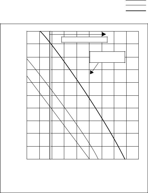
2.SW4-9 setting
Fan characteristics curve:DIPSW4-7OFF[FactorySetting],208V•230V/60Hz Fan characteristics curve:DIPSW4-7ON,208V/60Hz
Fan characteristics curve:DIPSW4-7ON,230V/60Hz
|
50 |
|
|
|
|
|
|
|
|
|
|
|
|
|
Continuous operation range |
|
|
|
|||
|
45 |
|
|
|
|
|
|
|
|
|
|
40 |
|
|
|
|
|
Standard Airflow rate |
|
||
|
|
|
|
|
|
200(m3/min) |
|
|
||
(Pa) |
35 |
|
|
|
|
|
|
|
|
|
|
|
|
|
|
|
|
|
|
|
|
pressure |
30 |
|
|
|
|
|
|
|
|
|
25 |
|
|
|
|
|
|
|
|
|
|
static |
|
|
|
|
|
|
|
|
|
|
20 |
|
|
|
|
|
|
|
|
|
|
External |
|
|
|
|
|
|
|
|
|
|
15 |
|
|
|
|
|
|
|
|
|
|
|
10 |
|
|
|
|
|
|
|
|
|
|
5 |
|
|
|
|
|
|
|
|
|
|
0 |
|
|
|
|
|
|
|
|
|
|
150 |
160 |
170 |
180 |
190 |
200 |
210 |
220 |
230 |
240 |
Airflow rate (m3/min)
- 12 -
(2)Indoor unit DIP SW1, 3
Switch |
SW name |
Operation by SW |
Switch set timing |
Remarks |
||||
|
|
|
|
|||||
OFF |
ON |
OFF |
ON |
|||||
|
|
|
|
|||||
|
|
|
|
|
|
|
|
|
|
1 |
Room temp. sensor position |
Indoor unit inlet |
Built in remote controller |
|
|
|
|
|
2 |
Clogged filter detect. |
None |
Provided |
|
|
|
|
|
3 |
Filter duration |
100h |
2500h |
|
|
|
|
|
|
|
|
|
|
|
|
|
|
4 |
OA intake |
Ineffective |
Effective |
|
|
Always ineffective for PKFY-NAMU |
|
|
5 |
Remote display select. |
Fan output display |
Thermo. ON signal display |
|
|
|
|
SW1 |
6 |
Humidifier control |
At stationary heating |
Always at heat. |
|
|
|
|
|
|
|
|
|||||
|
|
|
|
|
|
|
|
|
|
7 |
Heating thermo. OFF airflow |
Very low speed |
Low speed |
|
|
|
|
|
8 |
Heating thermo. OFF airflow |
SW1-7 setting |
Set airflow |
|
|
|
|
|
9 |
Power failure automatic |
Ineffective |
Effective |
|
|
|
|
|
return |
|
|
|
||||
|
|
|
|
|
|
|
||
|
10 |
– |
– |
– |
|
|
|
|
|
1 |
Model selection |
Heat pump |
Cool.only |
At unit stopping |
|
||
|
2 |
Cooling capacity saving |
None |
Provided |
(at remote |
|
||
|
Louver for PKFY-NAMU, |
controller OFF) |
|
|||||
|
|
effective/ineffective |
|
|
|
|
|
|
|
3 |
Vane |
None |
Provided |
|
|
|
|
|
|
|
|
|
|
|
|
|
|
4 |
Vane swing function |
None |
Provided |
|
|
Not provided for PKFY-NAMU |
|
|
|
|
Provided for PLFY-NGMU (ON) setting |
|||||
|
|
|
|
|
|
|
||
SW3 |
5 |
Vane horizontal angle |
1st setting |
2nd setting |
|
|
|
|
|
6 |
Vane angle set for cooling |
Down blow B, C |
Horizontal |
|
|
Always down blow B,C for |
|
|
|
|
PKFY-NAMU |
|||||
|
|
|
|
|
|
|
||
|
7 |
– |
– |
– |
|
|
|
|
|
8 |
Heating 4deg (7.2 deg) up |
Effective |
Ineffective |
|
|
|
|
|
Note : ° C scale (° F scale) |
|
|
|
||||
|
|
|
|
|
|
|
||
|
|
|
|
|
|
|
|
|
|
9 |
– |
– |
– |
|
|
|
|
|
|
|
|
|
|
|
|
|
|
10 |
– |
– |
– |
|
|
|
|
|
|
|
|
|
|
|
|
|
Note 1: The shaded part 
 indicates the setting at factory shipment. (For the SW not being shaded, refer to the table below.)
2:The DipSW setting is only effective during unit stopping (remote controller OFF) for SW1, 2, 3 and 4 commonly and the power source is not required to reset.)
3:When both SW1-7 and SW1-8 are being set to ON, the fan stops at the heating thermostat of OFF.
|
Model |
PLFY-NAMU-A |
PDFY-NMU-A |
|
PKFY |
||
|
|
|
|
|
|
||
Switch |
NAMU-A |
|
NGMU-A |
||||
|
|
|
|||||
|
|
3 |
ON |
ON |
|
OFF |
|
|
|
|
|
|
|
|
|
SW1 |
|
6 |
ON |
ON |
|
OFF |
|
|
|
|
|
|
|
|
|
|
7 |
OFF |
OFF |
|
OFF |
||
|
|
|
|||||
|
|
|
|
|
|
|
|
|
|
3 |
ON |
OFF |
|
ON |
|
|
|
|
|
|
|
|
|
SW3 |
|
4 |
ON |
OFF |
OFF |
|
ON |
|
|
|
|
|
|
|
|
|
6 |
OFF |
OFF |
|
OFF |
||
|
|
|
|||||
|
|
|
|
|
|
|
|
|
|
8 |
OFF |
OFF |
|
OFF |
|
|
|
|
|
|
|
|
|
Setting of DIP SW2
Model |
|
08 |
|
|
10 |
|
|
|
12 |
|
|
16 |
|
|
20 |
|
24 |
|
|||||||||
|
|
|
|
|
|
|
|
|
|
|
|
|
|
|
|
|
|
|
|
|
|
|
|
|
|
|
|
Capacity (model name) code |
|
4 |
|
|
5 |
|
|
|
6 |
|
|
8 |
|
|
10 |
|
13 |
|
|||||||||
|
|
|
|
|
|
|
|
|
|
|
|
|
|
|
|
|
|
|
|
|
|
|
|
|
|
|
|
SW2 setting |
ON |
|
|
|
ON |
|
|
|
|
|
|
ON |
|
|
|
|
ON |
|
|
ON |
|
|
ON |
|
|
||
OFF |
|
|
|
OFF |
|
|
|
|
|
|
OFF |
|
|
|
|
OFF |
|
|
OFF |
|
|
OFF |
|
|
|||
|
|
|
|
|
|
|
|
|
|
|
|
|
|
|
|
|
|
|
|
|
|
|
|
|
|
|
|
|
|
|
|
|
|
|
|
|
|
|
|
|
|
|
|
|
|
|
|
|
|
|
|
|
|
|
|
Model |
|
32 |
|
|
40 |
|
|
|
48 |
|
|
|
|
|
|
|
|
|
|
||||||||
Capacity (model name) code |
|
16 |
|
|
20 |
|
|
|
25 |
|
|
|
|
|
|
|
|
|
|
||||||||
|
|
|
|
|
|
|
|
|
|
|
|
|
|
|
|
|
|
|
|
|
|
|
|
|
|||
SW2 setting |
ON |
|
|
|
ON |
|
|
|
|
|
|
|
ON |
|
|
|
|
|
|
|
|
|
|
|
|||
|
|
|
|
|
|
|
|
|
|
|
|
|
|
||||||||||||||
OFF |
|
|
|
OFF |
|
|
|
|
|
|
|
OFF |
|
|
|
|
|
|
|
|
|
|
|
||||
|
|
|
|
|
|
|
|
|
|
|
|
|
|
|
|
|
|
|
|
|
|
|
|
|
|
|
|
- 13 -
Setting of DIP SW4 |
|
|
|
|
|
|
Setting of DIP SW5 |
|||||
|
|
|
|
|
|
|
|
|
|
|
|
|
Model |
Circuit board used |
|
|
SW4 |
|
|
|
|
|
|
|
|
1 |
2 |
|
3 |
4 |
|
|
|
|
|
|
||
|
|
|
|
|
|
|
|
|
||||
PDFY-10 ~ 32 |
|
ON |
OFF |
|
ON |
OFF |
|
|
|
|
|
|
|
|
|
|
|
|
|
|
|||||
PLFY-12 ~ 24 |
Phase control |
OFF |
OFF |
|
OFF |
ON |
|
|
|
|
|
|
|
|
|
|
|
|
|
||||||
PLFY-32 ~ 48 |
ON |
OFF |
|
OFF |
ON |
|
|
|
|
|
|
|
|
|
|
|
|
|
|
|
|
|
|
|
|
PKFY-P-8 |
|
OFF |
OFF |
|
ON |
ON |
|
|
|
|
|
|
|
|
|
|
|
|
|
|
|
|
|
|
|
PKFY-P-12 |
|
– |
– |
|
– |
– |
|
|
|
|
|
|
PDFY-40, 48 |
Relay selection |
OFF |
OFF |
|
ON |
– |
|
|
|
|
|
|


- 14 -
2TEST RUN
[1]Before Test Run
(1) Check points before test run
1 Neither refrigerant leak nor loose power source/ transmission lines should be found, if found correct immediately.
2 Confirm that the resistance between the power source terminal block and the ground exceeds 2MΩ by measuring it with a DC500V megger. Do not run if it is lower than 2MΩ .
Note : Never apply the megger to the MAIN board. If applied, the MAIN board will be broken.
3Confirm that the Ball valve at both gas and liquid sides are fully opened. Note : Close the cap.
4Be sure that the crankcase heater has been powered by turning the main power source on at least 12 hours before starting the test run. The shorter powering time causes compressor trouble.
(2)Caution at inverter check
Because the inverter power portion in outdoor unit electrical part box have a lot of high voltage portion, be sure to follow the instructions shown below.
During energizing power source, never touch inverter power portion because high voltage (approx. 320V) is
1applied to inverter power portion.
When checking,
1Shut off main power source, and check it with tester, etc.
2Allow 10 minutes after shutting off main power source.
3Open the MAIN board mounting panel, and check whether voltage of both ends of electrolytic capacitor is 20V or less.
- 15 -
(3) Check points for test run when mounting options
Built-in optional parts |
|
Content of test run |
Check point |
Result |
|
|
|
|
|
Mounting of drain |
1 |
Release connector of pump circuit, |
Local remote controller displays code |
|
water pump |
|
check error detection by pouring |
No. “2503”, and the mechanism stops. |
|
mechanism |
|
water into drain pan water inlet. |
|
|
|
No overflow from drain pan. |
|
||
|
|
|
|
|
|
|
|
|
|
|
2 |
After that, connect connector of |
Drain water comes out by operation of |
|
|
|
circuit. |
drain pump. |
|
|
|
|
|
|
|
3 |
Check pump operations and drain- |
Sound of pump operations is heard, and |
|
|
|
age status in cooling (test run) mode. |
drain water comes out. |
|
|
|
|
|
|
Mounting of perme- |
Check humidifier operations and water |
No water leak from connecting portions |
|
|
able film humidifier |
supply status in heating (test run) mode. |
of each water piping. |
|
|
|
|
|
|
|
|
|
|
Water is supplied to water supply tank, |
|
|
|
|
and float switch is operating. |
|
|
|
|
|
|
(4) Attention for mounting drain water pump mechanism
Work |
|
Content of test run |
|
Check point |
Result |
|
|
|
|
|
|
Disassembling and |
1 |
Lead wire from control box not |
|
|
|
assembling of drain |
|
damaged. |
|
|
|
water pump |
|
|
|
|
|
|
|
|
|
|
|
mechanism |
2 |
Rubber cap properly inserted in to |
|
pipe |
|
|
|
drain water outlet of drain pan? |
|
|
|
|
|
|
|
|
|
|
3 |
Insulation pipe of gas and liquid |
|
|
|
|
pipes dealt with as shown on next |
|
|
|
|
|
|
|
|
|
|
|
|
page? |
|
|
|
|
|
|
|
|
|
|
4 |
Drain pan and piping cover mounted |
|
|
|
|
|
without gap? |
|
|
|
|
|
|
|
|
|
|
5 |
Drain pan hooked on cut projection |
|
|
|
|
of the mechanism? |
|
|
|
|
|
|
|
|
|
|
|
|
|
|
||
Mounting of float |
Float switch installed without contacting the |
1 Float switch moves smoothly. |
|
||
switch |
drain pan? |
|
|
|
|
2 |
Float switch is mounted on |
|
|||
|
|
|
|
||
|
|
|
mounting board straight without |
|
|
|
|
|
|
|
|
|
|
|
|
deformation. |
|
|
|
|
|
|
|
|
|
|
3 Float switch does not contact the |
|
|
|
|
|
|
copper pipe. |
|
|
|
|
|
|
|
Electric wiring |
1 |
No mistakes in wiring? |
Wiring procedure is exactly followed. |
|
|
|
|
|
|
|
|
|
2 |
Connectors connected securely and |
Connector portion is tightly hooked. |
|
|
|
tightly? |
|
|
|
|
|
|
|
|
|
|
|
|
|
|
|
|
|
3 |
No tension on lead wire when sliding |
|
|
|
|
control box? |
|
|
|
|
|
|
|
|
|
|
|
|
|
|
|
|
- 16 -
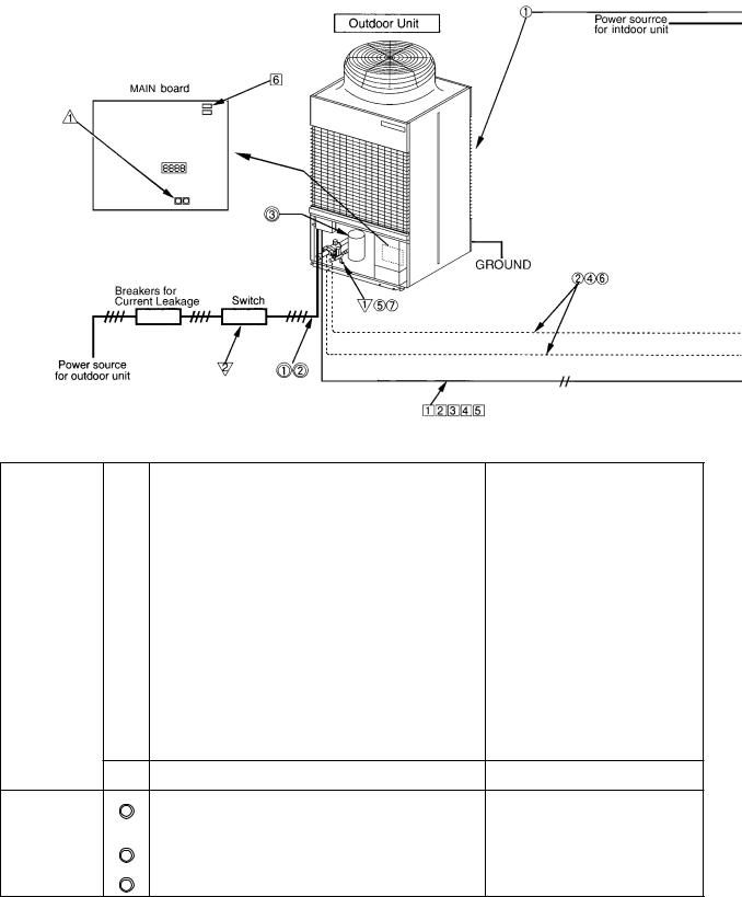
(5)Check points for system structure
Check points from installation work to test run.
Classification Portion |
Check item |
Trouble |
|
|
|
|
|
|
|
Installation and |
|
Instruction for selecting combination of outdoor unit, |
|
|
piping |
1 |
and indoor unit followed? (Maximum number of indoor |
Not operate. |
|
|
units which can be connected, connecting model name, |
|
||
|
|
and total capacity.) |
|
|
|
|
|
|
|
|
2 |
Follow limitation of refrigerant piping length? For example, |
|
|
|
70m (229ft) or less (total length : 220m (721ft)) at the farthest. |
Not cool (at cooling). |
|
|
|
3 |
Connecting piping size of branch piping correct? |
Not heat (at heating). |
|
|
|
|
|
|
|
4 |
Refrigerant piping diameter correct? |
|
|
|
|
|
||
|
|
|
|
|
|
5 |
Refrigerant leak generated at connection? |
Not cool, not heat, error stop. |
|
|
|
|
|
|
|
6 |
Insulation work for piping properly done? |
Condensation drip in piping. |
|
|
|
|
|
|
|
7 |
Specified amount of refrigerant replenished? |
Not cool, not heat, error stop. |
|
8Pitch and insulation work for drain piping properly done? Water leak, condensation drip in drain piping.
Power source |
1 |
Specified switch capacity and wiring diameter of main |
Error stop, not operate. |
|
wiring |
power source used? |
|||
|
|
|||
|
|
|
|
|
|
2 |
Proper grounding work done on outdoor unit? |
Electric shock. |
|
|
|
|
|
|
|
3 |
The phases of the L line (L1, L2, L3) correct? |
Error stop, not operate. |
- 17 -
DRY COOL |
CENTRALLY CONTROLLED |
|
SENSOR |
DRY COOL |
CENTRALLY CONTROLLED |
|
SENSOR |
|||
AUTO FAN |
DAILY TIMER |
AUTO AUTO |
FAN |
INSIDE |
AUTO FAN |
DAILY TIMER |
AUTO AUTO |
FAN |
INSIDE |
|
CLOCK ON OFF |
FILTER |
CLOCK ON OFF |
FILTER |
|||||||
|
SPEED |
|
SPEED |
|||||||
HEAT |
CHECK SET TEMP. |
REMAINDER |
|
|
HEAT |
CHECK SET TEMP. |
REMAINDER |
|
|
|
STAND BY |
VENTILATION |
TEST RUN |
STAND BY |
VENTILATION |
TEST RUN |
DEFROST |
EROR CODE NOT AVAILABLE |
|
DEFROST |
EROR CODE NOT AVAILABLE |
|
SET TEMP. |
|
ON/OFF |
SET TEMP. |
|
ON/OFF |
1 |
2 |
3 |
MODE |
TIMER |
CLOCK ON OFF FAN SPEED |
AIR DIRECTION FILTER |
MODE |
TIMER |
CLOCK ON OFF FAN SPEED |
AIR DIRECTION FILTER |
|
|
|
||||||||
|
|
|
|
|
LOUVER |
VENTILATION CHECK TEST |
|
|
LOUVER |
VENTILATION CHECK TEST |
|
|
|
PAR-F27MEA-US |
TIMER SET |
|
PAR-F27MEA-US |
TIMER SET |
|
||
Classification |
Portion |
Check item |
Trouble |
|
|
|
|
Transmission |
1 |
Limitation of transmission line length followed? For example, |
Erroneous operation, error stop. |
line |
200m (656ft) or less (total length : 500m (1640ft)) at the farthest. |
|
|
|
|
|
|
|
2 |
1.25mm2 (AWG16) or more transmission line used? |
Erroneous operation, error stop. |
|
|
(Remote controller 10m (32ft) or less 1.25mm2 (AWG16)) |
|
|
3 |
2-core cable used for transmission line? |
Error stop in case multiple-core |
|
|
|
cable is used. |
|
|
|
|
|
4 |
Transmission line apart from power source line by 5cm (2in) or more? |
Erroneous operation, error stop. |
|
|
|
|
|
5 |
One refrigerant system per transmission line? |
Not operate. |
|
|
|
|
|
6 |
The short circuit connector is changed form CN41 to |
Not operate. |
|
|
CN40 on the MAIN board when the system is centralized |
|
|
|
control? (Just one outdoor unit. Not all outdoor units.) |
|
|
|
|
|
|
7 |
• No connection trouble in transmission line? |
Error stop or not operate. |
|
|
|
|
|
8 |
Connection of wrong remote controller line terminals? |
Never finish the initial mode. |
|
|
• MA Remote controller : TB15 |
|
|
|
• M-NET Remote controller : TB5 |
|
|
|
|
|
System set |
1 |
Address setting properly done? (M-NET Remote |
Error stop or not operate. |
|
controller, indoor unit and outdoor unit.) |
|
|
|
|
|
|
|
|
|
|
|
2 |
Setting of address No. done when shutting off power |
Can not be properly set with power |
|
source? |
source turned on. |
|
|
|
||
|
|
|
|
|
3 |
Address numbers not duplicated? |
Not operate. |
|
|
|
|
|
4 |
Turned on SW3-8 on indoor unit circuit board when |
Set temperature not obtained at |
|
mounting room thermistor sensor? |
heating operations (Thermostat |
|
|
|
||
|
|
|
stop is difficult) |
|
|
|
|
Before starting |
1 |
Refrigerant piping ball valve (Liquid pressure pipe, gas |
Error stop. |
|
|
pressure pipe) opened? |
|
2Turn on power source 12 hours before starting operations? Error stop, compressor trouble.
-18 -
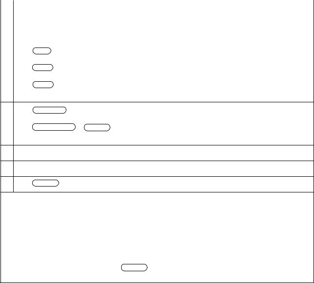
[2] |
Test Run Method |
||
|
|
|
|
|
|
|
Operation procedure |
|
|
||
1 |
Turn on universal power supply at least 12 hours before starting → Displaying “HO” on display panel for about two |
||
|
minutes |
|
|
|
|
|
|
2 |
Press |
TEST |
button twice → Displaying “TEST RUN’’ on display panel |
|
|
|
|
3 |
Press |
MODE |
button → Make sure that air is blowing out |
|
|
|
|
|
Press |
MODE |
button to change from cooling to heating operation, and vice versa Make sure that warm or cold |
4air is blowing out
5 Press |
FAN SPEED adjust button → |
Make sure that air blow is changed |
|
|
|
Press |
AIR DIRECTION or LOUVER |
button to change direction of air blowing make sure that horizontal or |
6downward blow is adjustable.
7Make sure that indoor unit fans operate normally
8Make sure that interlocking devices such as ventilator operate normally if any
9 Press ON/OFF button to cancel test run → Stop operation
Note 1: If check code is displayed on remote controller or remote controller does not operate normally.
2:Test run automatically stops operating after two hours by activation of timer set to two hours.
3:During test run, test run remaining time is displayed on time display section.
4:During test run, temperature of liquid pipe in indoor unit is displayed on remote controller room temperature display section.
5: When pressing  adjust button, depending on the model, “NOT AVAILABLE” may be displayed on remote controller. However, it is not a malfunction.
6: When pressing  or LOUVER button, depending on the model, “NOT AVAILABLE” may be displayed on remote controller. However, it is not a malfunction.
- 19 -
3GROUPING REGISTRATION OF INDOOR UNITS WITH M-NET REMOTE CONTROLLER
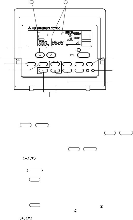
(1)Switch function
• The switch operation to register with the remote controller is shown below:
i |
ii |
DRY COOL |
CENTRALLY CONTROLLED |
|
SENSOR |
|||
AUTO FAN |
DAILY TIMER |
AUTO AUTO |
FAN |
INSIDE |
||
CLOCK ON |
OFF |
|
||||
|
SPEED |
FILTER |
||||
HEAT |
CHECK SET TEMP. |
REMAINDER |
||||
|
|
|||||
|
STAND BY |
|
EROR CODE |
VENTILATION |
TEST RUN |
|
|
C Switch to assign |
DEFROST |
|
NOT AVAILABLE |
|
|
||
|
|
|
|
|
|
||
indoor unit address |
|
SET TEMP. |
|
ON/OFF |
|
||
F Delete switch |
|
|
|
|
|
A Registration/ |
|
G Registered mode |
MODE |
TIMER |
CLOCK ON OFF FAN SPEED AIR DIRECTION FILTER |
ordinary mode |
|||
selector switch |
|||||||
|
|
|
|
|
|
||
selector switch
E Confirmation switch
LOUVER |
VENTILATION CHECK TEST |
DRegistration switch
PAR-F27MEA-US |
TIMER SET |
B Registration/ ordinary mode selector switch
HSwitch to assign interlocked unit address
Name |
Symbol |
Name of actual switch |
Description |
|
|
of switch |
|
||||
|
|
|
|
||
|
|
|
|
|
|
Registration/ordinary |
A + |
B |
FILTER + LOUVER |
This switch selects the ordinary mode or registered mode (ordinary |
|
mode selection switch |
|
|
|
mode represents that to operate indoor units). |
|
|
|
|
|
||
|
|
|
|
To select the registered mode, press the |
FILTER + LOUVER |
|
|
|
|
button continuously for over 2 seconds under stopping state. |
|
|
|
|
|
[Note] The registered mode can not be obtained for a while after |
|
|
|
|
|
powering. |
|
|
|
|
|
Pressing the FILTER + LOUVER button displays “CENTRALLY |
|
|
|
|
|
CONTROLLED”. |
|
|
|
|
|
|
|
Switch to assign indoor |
C |
|
of TEMP |
This button assigns the unit address for “INDOOR UNIT ADDRESS |
|
unit address |
|
|
|
NO.” |
|
|
|
|
|
|
|
|
|
|
|
|
|
Registration switch |
D |
|
TEST RUN |
This button is used for group/interlocked registration. |
|
|
|
|
|
||
|
|
|
|
||
Confirmation switch |
E |
TIMER |
This button is used to retrieve/identify the content of group and |
||
|
|
|
interlocked (connection information) registered. |
||
|
|
|
|
|
|
Delete switch |
F |
|
CLOCK→ |
This button is used to retrieve/identify the content of group and |
|
|
|
|
ON→ OFF |
interlocked (connection information) registered. |
|
|
|
|
|
|
|
Registered mode |
G |
|
|
This button selects the case to register indoor units as group (group |
|
selector switch |
|
|
|
setting mode) or that as interlocked (interlocked setting mode). |
|
|
|
|
MODE |
||
|
|
|
The unit address is shown at one spot |
for the group setting mode |
|
|
|
|
|
||
|
|
|
|
while at two spots for the interlocked setting mode. |
|
|
|
|
|
|
|
Switch to assign |
H |
|
of TIMER SET |
This button assigns the unit address of “OA UNIT ADDRESS NO.” |
|
interlocked unit address |
|
|
|
|
|
|
|
|
|
|
|
- 20 -
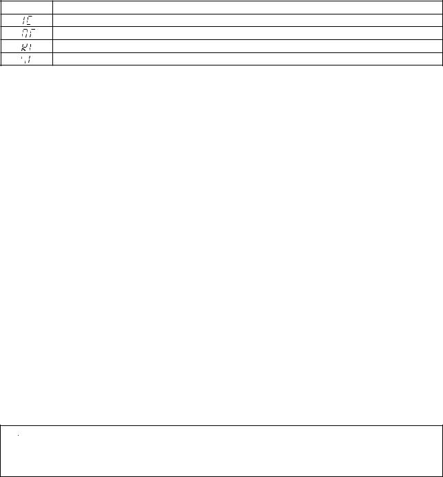
(2) Attribute display of unit
•At the group registration and the confirmation/deletion of registration/connection information, the type (attribute) of the unit is displayed with two English characters.
Display |
Type (Attribute) of unit/controller |
Indoor unit connectable to remote controller
Outdoor unit
Local remote controller
System controller (MJ)
[Description of registration/deletion/retrieval]
•The items of operation to be performed by the remote controller are given below. Please see the relating paragraph for detail.
1Group registration of indoor unit
•The group of the indoor units and operating remote controller is registered.
•It is usually used for the group operation of indoor units with different refrigerant system.
2Retrieval/identification of group registration information of indoor units
•The address of the registered indoor units in group is retrieved (identified).
3Retrieval/identification of registration information
•The connection information of any unit (indoor/outdoor units, remote controller or the like) is retrieved (identified).
4Deletion of group registration information of indoor units
•The registration of the indoor units under group registration is released (deleted).
5Deletion of the address not existing
•This operation is to be conducted when “6607” error (No ACK error) is displayed on the remote controller caused by the miss setting at test run, or due to the old memory remained at the alteration/modification of the group composition.
 Caution:
When MELANS (G-50 for example) is being connected, do not conduct the group/pair registration using
the remote controller. The group/pair registration should be conducted by MELANS. (For detail, refer to the instruction exclusively prepared for MELANS.)
- 21 -
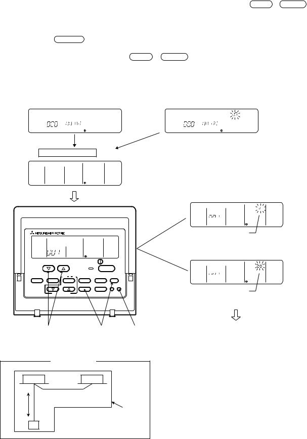
(3) Group registration of indoor unit
1)Registration method
•Group registration of indoor unit ........................................................................ 1
The indoor unit to be controlled by a remote controller is registered on the remote controller.
[Registration procedure]
1 With the remote controller under stopping or at the display of “HO”, continuously press the FILTER + LOUVER button ( A + B) at the same time for 2 seconds to change to the registration mode. (See the figure below.)
2Assign the indoor unit address to “INDOOR UNIT ADDRESS NO.” by operating the 
 (Room temperature adjustment) ( C).
Then press the TEST RUN button (D) to register. In the figure below, the “INDOOR UNIT ADDRESS NO.” is being set to 001.
3 After completing the registration, press the |
FILTER + LOUVER button ( A+ B) at the same time for 2 seconds to |
||||||||||||||
change to the original ordinary mode (with the remote controller under stopping). |
|||||||||||||||
|
|
|
|
|
|
|
|
|
|
|
|
|
|
|
|
|
Ordinary mode |
|
|
|
|
|
|
|
|
|
|||||
|
|
|
|
|
|
|
|
|
|
|
|
|
|
|
|
• Remote controller under stopping |
• “HO” under displaying |
||||||||||||||
|
|
|
|
|
|
|
|
|
|
|
|
|
|
|
|
|
|
|
|
|
|
|
|
|
|
|
|
|
|
|
|
|
|
|
|
|
|
|
|
|
|
|
|
|
|
|
|
|
|
|
˚C |
|
|
|
|
|
|
|
˚C |
|
|
|
|
|
|
|
INDOOR UNIT |
|
ERROR CODE |
|
|
|
|
INDOOR UNIT |
|
ERROR CODE |
|
|
|
|
|
|
ADDRESS NO |
|
OAUNITADDRESSNO |
|
|
|
|
ADDRESS NO |
|
OAUNITADDRESSNO |
|
|
|
11
Group setting mode


 ˚C
˚C
ERROR CODE
OAUNITADDRESSNO
• Registration complete


 ˚C
˚C
ERROR CODE
OAUNITADDRESSNO
Indicates the type of unit (Indoor unit in this case)
2 + 3
• Registration error


 ˚C
˚C
ERROR CODE
OAUNITADDRESSNO
“88” flickers indicating registration error. (when the indoor unit registered is not existing)
2 Assign the |
1 Change to the |
3Press the |
• |
address (C) |
registration |
registration |
• |
|
mode ( A+ B) |
switch (D) |
|
|
|
||
System example |
|
|
|
|
Indoor units |
|
|
|
Group |
|
|
Remote controller |
|
|
|
|
|
- 22 - |
|
Confirm the indoor unit address No.
Confirm the connection of the transmission line.
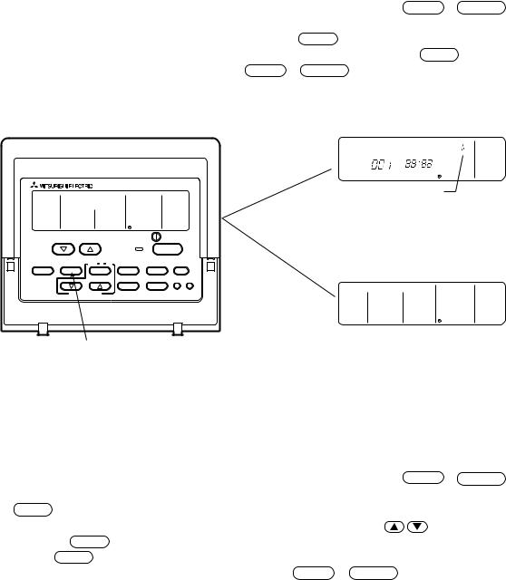
2)Method of retrieval/confirmation
•Retrieval/confirmation of group registration information on indoor unit............... 2
The address of the indoor unit being registered on the remote controller is displayed.
[Operation procedure]
1With the remote controller under stopping or at the display of “HO”, continuously press the FILTER + LOUVER button (A+ B) at the same time for 2 seconds to change to the registration mode.
2In order to confirm the indoor unit address already registered, press TIMER button (E). (See figure below.) When the group of plural sets is registered, the addresses will be displayed in order at each pressing of TIMER button (E).
3After completing the registration, continuously press the FILTER + LOUVER button ( A+ B) at the same time for 2 seconds to change to the original ordinary mode (with the remote controller under stopping).
• Registered
|
SET TEMP. |
ON/OFF |
|
MODE |
TIMER |
CLOCK ON OFF FAN SPEED |
AIR DIRECTION FILTER |
|
|
LOUVER |
VENTILATION CHECK TEST |
PAR-F27MEA-US |
TIMER SET |
|
|
|
|
|
|
|
|
|
|
|
|
|
|
|
|
|
|
|
|
|
|
|
|
|
|
˚C |
|
|
|
|
|
|
|
|
ERROR CODE |
|
|
|
|
|
|
OAUNITADDRESSNO |
|
1 |
Indicates the type of unit |
|
||||
(Indoor unit in this case) |
|
|||||
• No registration.


 ˚C
˚C
ERROR CODE
OAUNITADDRESSNO
1Press the switch for confirmation (E)
Note: Only one address will be displayed when the registration is one even the switch is how often pressed
•Retrieval/confirmation of registration information ................................................ 3
The registered information on a certain unit (indoor unit, outdoor unit, remote controller or the like) is displayed.
[Operation procedure] |
|
1 With the remote controller under stopping or at the display of “HO”, continuously press the |
FILTER + LOUVER button |
(A + B) at the same time for 2 seconds to change to the registration mode. |
|
2 Operate MODE button (G) for the interlocked setting mode. (See figure below.) |
|
3 Assign the unit address of which registration information is desired to confirm with the |
(TIMER SET) switch |
(H). Then press the TIMER button (E) to display it on the remote controller. (See figure below.) Each pressing of TIMER button (E) changes the display of registered content. (See figure below.)
4 After completing the retrieval/confirmation, continuously press the FILTER + LOUVER button (A + B) at the same time for 2 seconds to change to the original ordinary mode (with the remote controller under stopping).
- 23 -
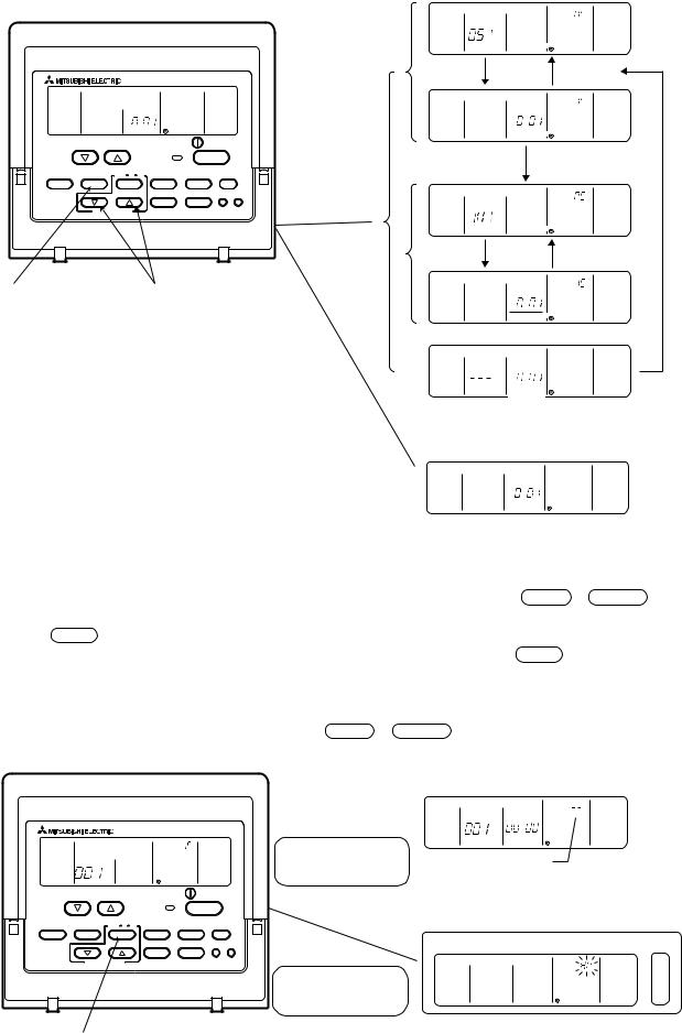
|
|
|
• Registered |
|
|
|
|
ß C |
|
|
|
|
(Alternative |
|
|
|
|
|
display) |
|
|
|
ß C |
|
|
SET TEMP. |
|
ON/OFF |
|
MODE |
TIMER CLOCK |
ON OFF FAN SPEED |
AIR DIRECTION FILTER |
|
|
|
LOUVER |
VENTILATION CHECK TEST |
|
PAR-F27MEA-US |
TIMER SET |
|
|
2 |
|
|
|
ß C |
|
|
|
|
|
|
|
|
|
1 + 2 |
|
|
|
|
(Alternative |
|
|
|
|
|
display) |
2 Press the switch for |
1Set the address |
|
||
confirmation (E) |
|
ß C |
|
|
|
|
|
˚C |
|
|
|
|
INDOOR UNIT |
ERROR CODE |
|
|
|
ADDRESS NO |
OAUNITADDRESSNO |
* Same display will appear when
the unit of “007” is not existing.
• No registration


 ˚C
˚C
ERROR CODE
OAUNITADDRESSNO
3)Method of deletion
• Deletion of group registration information of indoor unit ...................................... 4
[Operation procedure]
1With the remote controller under stopping or at the display of “HO”, continuously press the FILTER + LOUVER button ( A + B) at the same time for 2 seconds to change to the registration mode.
2 Press the TIMER button (E) to display the indoor unit address registered. (As same as 2)
3 In order to delete the registered indoor unit being displayed on the remote controller, press the TIMER CLOCK → ON→ OFF (F) button two times continuously. At completion of the deletion, the attribute display section will be shown as “– – “. (See figure below.)
Note: Completing the deletion of all indoor units registered on the remote controller returns to “HO” display.
4 After completing the registration, continuously press the FILTER + LOUVER button ( A+ B) at the same time for 2 seconds to change to the original ordinary mode (with the remote controller under stopping).
• Deletion completed
|
SET TEMP. |
ON/OFF |
|
MODE |
TIMER |
CLOCK ON OFF FAN SPEED |
AIR DIRECTION FILTER |
1
|
|
|
|
|
|
|
|
˚C |
|
|
|
In case of group re- |
INDOOR UNIT |
ERROR CODE |
|
||
ADDRESS NO |
OAUNITADDRESSNO |
|
|||
gistration with other |
“–” indicates the |
||||
indoor unit is existing |
deletion completed. |
||||
• Deletion completed
1
LOUVER |
VENTILATION CHECK TEST |
PAR-F27MEA-US |
TIMER SET |
1Press the switch for confirmation ( E ) twice continuously.
In case of no group registration with other indoor unit is existing
˚C |
|
INDOOR UNIT |
ERROR CODE |
ADDRESS NO |
OAUNITADDRESSNO |
- 24 -
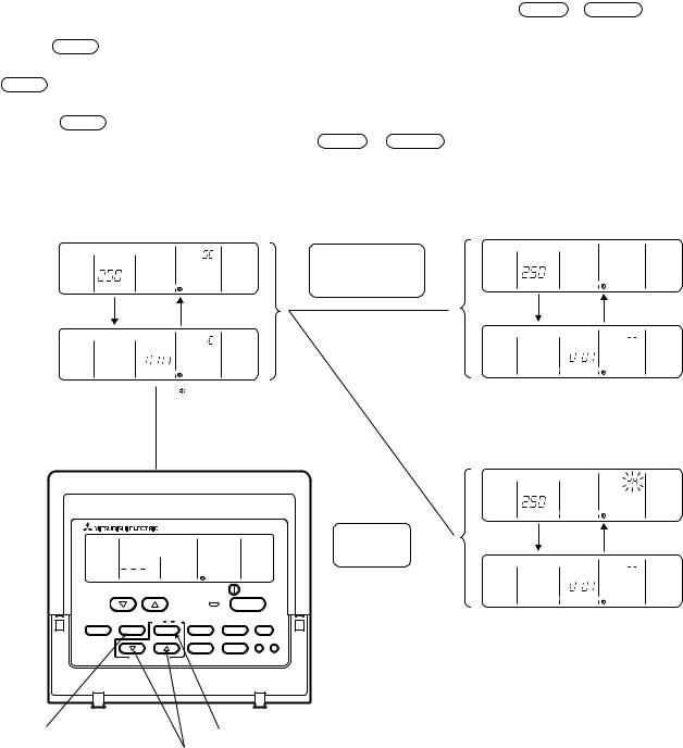
4)Deletion of information on address not existing
•Deletion of information on address not existing ................................................... 5
This operation is to be conducted when “6607” error (No ACK error) is displayed on the remote controller caused by the miss setting at test run, or due to the old memory remained at the alteration/modification of group composition, and the address not existing will be deleted.
Note: The connection information (connection between indoor unit and outdoor unit) on the refrigerant system can not be deleted.
An example to delete the system controller of “250” from the indoor unit of “007” is shown below.
[Operation procedure]
1With the remote controller under stopping or at the display of “HO”, continuously press the FILTER + LOUVER button (A+ B) at the same time for 2 seconds to change to the registration mode.
2Operate MODE button (G) for the interlocked setting mode ( ii ). (See the figure below.)
3Assign the unit address existing to “OA UNIT ADDRESS No.” with the 
 (TIMER SET) switch (H), and press TIMER button (E) to call the address to be deleted. (See the figure below.) As the error display on the remote controller is usually transmitted from the indoor unit, “OA UNIT ADDRESS No.” is used as the address of the indoor unit.
4Press the TIMER CLOCK → ON→ OFF button (F) twice. (See the figure below.)
5After completing the deletion, continuously press the FILTER + LOUVER button ( A+ B) at the same time for 2 seconds to return to the original ordinary mode (with the remote controller under stopping).
• Deletion completed
|
|
|
When both indoor |
|
|
|
|
|
|
unit and interlocked |
|
|
|
|
ß C |
|
unit addresses are |
ß C |
ERROR CODE |
|
INDOOR UNIT |
ERROR CODE |
existing |
INDOOR UNIT |
|||
ADDRESS NO |
OAUNITADDRESSNO |
|||||
ADDRESS NO |
OAUNITADDRESSNO |
|||||
|
(Alternative |
|
(Alternative |
|||
|
|
|
display) |
|||
|
|
display) |
3 |
|
||
|
|
|
|
|||
|
ß C |
|
|
ß C |
|
|
|
|
3 |
INDOOR UNIT |
ERROR CODE |
||
INDOOR UNIT |
ERROR CODE |
|||||
ADDRESS NO |
OAUNITADDRESSNO |
|||||
ADDRESS NO |
OAUNITADDRESSNO |
|||||
|
|
|||||
|
|
|
|
|
|
|
|
|
1+ 2 |
|
|
|
|
|
|
|
|
• Deletion completed |
||
|
|
|
|
ß C |
|
|
|
|
|
|
INDOOR UNIT |
ERROR CODE |
|
|
|
|
|
ADDRESS NO |
OAUNITADDRESSNO |
|
|
|
|
Deletion of |
(Alternative |
||
|
|
|
address not |
|
display) |
|
|
|
|
existing |
|
|
|
|
SET TEMP. |
ON/OFF |
ß C |
|
||
|
|
|
|
INDOOR UNIT |
ERROR CODE |
|
|
|
|
|
ADDRESS NO |
OAUNITADDRESSNO |
|
MODE |
TIMER CLOCK ON OFF FAN SPEED |
AIR DIRECTION FILTER |
|
|
||
|
|
|||||
|
|
LOUVER |
VENTILATION CHECK TEST |
|
|
|
PAR-F27MEA-US |
|
TIMER SET |
|
|
|
|
2Press the switch for |
3Press the deletion switch (F) twice |
confirmation (E) |
1 Set the address (H) |
|
- 25 -
4 CONTROL
[1]Control of Outdoor Unit
(1)Initial processing
•When turning on power source, initial processing of microcomputer is given top priority.
•During initial processing, control processing corresponding to operation signal is suspended. The control processing is resumed after initial processing is completed. (Initial processing : Data processing in microcomputer and initial setting of each LEV opening, requiring approx. 2 minutes at the maximum.)
(2)Control at staring
•In case unit is started within 2 hours after turning on power source at low outdoor air temperature (+5˚C (41 ° F) or
less), the unit does not start operating for 30 minutes at the maximum |
. |
(3)Bypass, capacity control
•Solenoid valve consists of bypass solenoid valve (SV1, SV2) bypassing between high pressure side and low pressure side. The following operation will be provided.
1)Bypass solenoid valves SV1 and SV2 (both "open" when turned on)
Item |
|
|
|
|
|
|
|
|
|
|
|
|
|
|
|
|
|
|
|
|
|
|
|
|
|
SV1 |
|
|
|
|
|
|
|
|
|
|
|
SV2 |
|||||||||||||||||||||||||||||||||||||||
|
|
|
|
|
|
|
|
|
|
|
|
|
|
|
|
|
|
|
|
|
|
|
|
|
|
|
|
|
|
|
|
|
|
|
|
|
|
|
|
|
|
|
|
|
|
|
|
|
|
|
|
|
|
|
|
|
|
|
|
|
|
|
|
|
|
|
|
|
|
|
|
|
|
|
|||
|
|
|
|
|
|
|
|
|
|
|
|
|
|
|
|
ON (Open) |
|
OFF (Close) |
|
|
ON (Open) |
|
|
|
|
|
|
|
|
|
|
|
|
OFF (Close) |
|||||||||||||||||||||||||||||||||||||||||||
|
|
|
|
|
|
|
|
|
|
|
|
|
|
|
|
|
|
|
|
|
|
|
|
|
|
|
|
|
|
|
|
|
|
||||||||||||||||||||||||||||||||||||||||||||
|
|
|
|
|
|
|
|
|
|
|
|
|
|
|
|
|
|
|
|
|
|
|
|
|
|
|
|
|
|
|
|
|
|
|
|
|
|
|
|
|
|
|
|
|
|
|
|
|
|
|
|
|
|
|
|
|
|
|
|
|
|
|
|
|
|
|
|
|
|
|
|
|
|
|
|
|
|
When starting compressor |
|
|
|
|
|
|
|
|
|
|
|
|
|
|
|
|
Turned on for 4 minutes |
|
|
|
|
|
|
|
|
|
|
|
|
|
|
|
|
|
|
|
|
|
|
|
|
|
|
|
|
||||||||||||||||||||||||||||||||
|
|
|
|
|
|
|
|
|
|
|
|
|
|
|
|
|
|
|
|
|
|
|
|
|
|
|
|
|
|
|
|
|
|
|
|
|
|
|
|
|
|
|
|
|
|
|
|
|
|
|
|
|
|
|
|
|
|
|
|
|
|
|
|
|
|
|
|
|
|
|
|
|
|
|
|
||
After thermost "ON is returned |
|
|
|
|
|
|
|
|
|
Turned on for 2 minutes |
|
|
|
|
|
|
|
|
|
|
|
|
|
|
|
|
|
|
|
|
|
|
|
|
|
|
|
|
|||||||||||||||||||||||||||||||||||||||
and after 3 minutes restart |
|
|
|
|
|
|
|
|
|
|
|
|
|
|
|
|
|
|
|
|
|
|
|
|
|
|
|
|
|
|
|
|
|
|
|
|
|
|
|
|
|
|
|
|
|
|
|
|
|
|
|
|
|
|
|
|
|
|
|
|
|
|
|
|
|
|
|
|
|
|
|
|
|
|
|
||
|
|
|
|
|
|
|
|
|
|
|
|
|
|
|
|
|
|
|
|
|
|
|
|
|
|
|
|
|
|
|
|
|
|
|
|
|
|
|
|
|
|
|
|
|
|
|
|
|
|
|
|
|
|
|
|
|
|
|
|
|
|
|
|
|
|
|
|
|
|
|
|
|
|
|
|
|
|
When compressor stops in |
|
|
|
|
|
|
|
|
|
|
|
|
|
|
|
|
Always turned on |
|
|
|
|
|
|
|
|
|
|
|
|
|
|
|
|
|
|
|
|
|
|
|
|
|
|
|
|
||||||||||||||||||||||||||||||||
cooling or heating mode |
|
|
|
|
|
|
|
|
|
|
|
|
|
|
|
|
|
|
|
|
|
|
|
|
|
|
|
|
|
|
|
|
|
|
|
|
|
|
|
|
|
|
|
|
|
|
|
|
|
|
|
|
|
|
|
|
|
|
|
|
|
|
|
|
|
|
|
|
|
|
|
|
|
|
|
||
|
|
|
|
|
|
|
|
|
|
|
|
|
|
|
|
|
|
|
|
|
|
|
|
|
|
|
|
|
|
|
|
|
|
|
|
|
|
|
|
|
|
|
|
|
|
|
|
|
|
|
|
|
|
|
|
|
|
|
|
|
|
|
|
|
|
|
|
|
|
|
|
|
|
|
|
|
|
After operation stops |
|
|
|
|
|
|
|
|
|
|
|
|
|
|
|
|
Turned on for 3 minutes |
|
|
|
|
|
|
|
|
|
|
|
|
|
|
|
|
|
|
|
|
|
|
|
|
|
|
|
|
||||||||||||||||||||||||||||||||
|
|
|
|
|
|
|
|
|
|
|
|
|
|
|
|
|
|
|
|
|
|
|
|
|
|
|
|
|
|
|
|
|
|
|
|
|
|
|
|
|
|
|
|
|
|
|
|
|
|
|
|
|
|
|
|
|
|
|
|
|
|
|
|
|
|
|
|
|
|
|
|
|
|
|
|
||
During defrosting operations |
|
|
|
|
|
|
|
|
|
Always turned on |
|
|
|
|
|
|
|
|
|
|
|
|
|
|
|
|
|
|
|
|
|
|
|
|
|
|
|
|
|||||||||||||||||||||||||||||||||||||||
(See figure below 1) |
|
|
|
|
|
|
|
|
|
|
|
|
|
|
|
|
|
|
|
|
|
|
|
|
|
|
|
|
|
|
|
|
|
|
|
|
|
|
|
|
|
|
|
|
|
|
|
|
|
|
|
|
|
|
|
|
|
|
|
|
|
|
|
|
|
|
|
|
|
|
|
|
|
|
|
||
|
|
|
|
|
|
|
|
|
|
|
|
|
|
|
|
|
|
|
|
|
|
|
|
|
|
|
|
|
|
|
|
|
|
|
|
|
|
|
|
|
|
|
|
|
|
|
|
|
|
|
|
|
|
|
|
|
|
|
|
|
|
|
|
|
|
|
|
|
|
|
|
|
|
|
|
||
During oil recovery operations |
|
|
Always turned on in oil recovery |
|
|
|
|
|
|
|
|
|
|
|
|
|
|
|
|
|
|
|
|
|
|
|
|
|
|
|
|
||||||||||||||||||||||||||||||||||||||||||||||
|
|
|
|
|
|
|
|
|
|
|
|
operation after low frequency |
|
|
|
|
|
|
|
|
|
|
|
|
|
|
|
|
|
|
|
|
|
|
|
|
|
|
|
|
|
||||||||||||||||||||||||||||||||||||
|
|
|
|
|
|
|
|
|
|
|
|
continuous operations |
|
|
|
|
|
|
|
|
|
|
|
|
|
|
|
|
|
|
|
|
|
|
|
|
|
|
|
|
|
||||||||||||||||||||||||||||||||||||
|
|
|
|
|
|
|
|
|
|
|
|
|
|
|
|
|
|
|
|
|
|
|
|
|
|
|
|
|
|
|
|
|
|
|
|
|
|
|
|
|
|
|
|
|
|
|
|
|
|
|
|
|
|
|
|
|
|
|
|
|
|
|
|
|
|
|
|
|
|
|
|
|
|
|
|
|
|
During 20Hz operations, at fall |
|
|
|
|
|
|
|
|
|
|
|
|
|
|
|
|
|
|
|
|
|
|
|
|
|
|
|
|
|
|
|
|
|
|
|
|
|
|
When low pressure |
|
When low pressure |
||||||||||||||||||||||||||||||||||||
in low pressure saturation |
|
|
|
|
|
|
|
|
|
|
|
|
|
|
|
|
|
|
|
|
|
|
|
|
|
|
|
|
|
|
|
|
|
|
|
|
|
|
|
|
|
|
|
|
|
|
saturation temp. (ET) |
|
saturation temp. |
||||||||||||||||||||||||||||
temperature. (ET) (3 minutes or |
|
|
|
|
|
|
|
|
|
|
|
|
|
|
|
|
|
|
|
|
|
|
|
|
|
|
|
|
|
|
|
|
|
|
|
|
|
|
|
is -30˚C (-22° F) or less |
|
(ET) is -15˚C (5° F) or |
|||||||||||||||||||||||||||||||||||
more after starting) |
|
|
|
|
|
|
|
|
|
|
|
|
|
|
|
|
|
|
|
|
|
|
|
|
|
|
|
|
|
|
|
|
|
|
|
|
|
|
|
|
|
|
|
|
|
|
|
|
|
|
|
|
|
|
|
|
|
|
|
|
more |
||||||||||||||||
|
|
|
|
|
|
|
|
|
|
|
|
|
|
|
|
|
|
|
|
|
|
|
|
|
|
|
|
|
|
|
|
|
|
|
|
|
|
|
|
|
|
|
|
|
|
|
|
|
|
|
|
|
|
|
|
|
|
|
|
|
|
|
|
|
|
|
|
|
|
|
|
|
|
|
|
||
When high pressure rises (Pd) |
|
|
When Pd reaches |
When Pd is |
When Pd reaches |
|
When Pd is 23kg/ |
||||||||||||||||||||||||||||||||||||||||||||||||||||||||||||||||||||||
|
|
|
|
|
|
|
|
|
|
|
|
27.5kg/cm2G |
|
|
|
|
|
|
24kg/cm2G (341psi) or |
26kg/cm2G (370psi) |
|
cm2G (327psi) or less |
|||||||||||||||||||||||||||||||||||||||||||||||||||||||
|
|
|
|
|
|
|
|
|
|
|
|
(391psi) or more |
less 30 seconds |
or more |
|
after 30 seconds |
|||||||||||||||||||||||||||||||||||||||||||||||||||||||||||||
|
|
|
|
|
|
|
|
|
|
|
|
|
|
|
|
|
|
|
|
|
|
|
|
|
|
|
|
|
|
|
|
|
|
|
|
|
|
|
|
|
|
|
|
|
|
|
|
|
|
|
|
|
|
|
|
|
|
|
|
|
|
|
|
|
|
|
|
|
|
|
|
|
|
|
|
|
|
When high pressure rises (Pd) |
|
|
|
|
|
|
|
|
|
|
|
|
|
|
|
|
|
|
|
|
|
|
|
|
|
|
|
|
|
|
|
|
|
|
|
|
|
|
Turned on when high |
|
When high pressure |
||||||||||||||||||||||||||||||||||||
during 20Hz operations |
|
|
|
|
|
|
|
|
|
|
|
|
|
|
|
|
|
|
|
|
|
|
|
|
|
|
|
|
|
|
|
|
|
|
|
|
|
|
|
|
|
|
|
|
|
|
pressure (Pd) ex- |
|
(Pd) is 20kg/cm2G |
||||||||||||||||||||||||||||
(3 minutes after starting) |
|
|
|
|
|
|
|
|
|
|
|
|
|
|
|
|
|
|
|
|
|
|
|
|
|
|
|
|
|
|
|
|
|
|
|
|
|
|
|
|
|
|
|
|
|
|
ceeds pressure limit |
|
(284psi) or less |
||||||||||||||||||||||||||||
|
|
|
|
|
|
|
|
|
|
|
|
|
|
|
|
|
|
|
|
|
|
|
|
|
|
|
|
|
|
|
|
|
|
|
|
|
|
|
|
|
|
|
|
|
|
|
|
|
|
|
|
|
|
|
|
|
|
|
|
|
|
|
|
|
|
|
|
|
|
|
|
|
|
|
|
|
|
When discharge temperature |
|
|
|
|
|
|
|
|
|
|
|
|
|
|
|
|
|
|
|
|
|
|
|
|
|
|
|
|
|
|
|
|
|
|
|
|
|
|
When temp. exceeds |
|
When discharge |
||||||||||||||||||||||||||||||||||||
rises |
|
|
|
|
|
|
|
|
|
|
|
|
|
|
|
|
|
|
|
|
|
|
|
|
|
|
|
|
|
|
|
|
|
|
|
|
|
|
|
|
|
|
|
|
|
|
130˚C (266° F) and Pd reaches |
|
temp. is 115˚C |
||||||||||||||||||||||||||||
(3 minutes after starting) |
|
|
|
|
|
|
|
|
|
|
|
|
|
|
|
|
|
|
|
|
|
|
|
|
|
|
|
|
|
|
|
|
|
|
|
|
|
|
|
|
|
|
|
|
|
|
15kg/cm2G (213psi) or more |
|
(239° F) or less |
||||||||||||||||||||||||||||
|
|
|
|
|
|
|
|
|
|
|
|
|
|
|
|
|
|
|
|
|
|
|
|
|
|
|
|
|
|
|
|
|
|
|
|
|
|
|
|
|
|
|
|
|
|
|
|
|
|
|
|
|
|
|
|
|
|
|
|
|
|
|
|
|
|
|
|
|
|
|
|
|
|
|
|
|
|
Ex. SV1 |
|
|
|
|
|
|
|
|
|
|
|
|
|
|
|
|
|
|
|
|
|
|
|
|
|
|
|
|
|
|
|
|
|
|
|
|
|
|
|
|
|
|
|
|
|
|
|
|
|
|
|
|
|
|
|
|
|
|
|
|
|
|
|
|
|
|
|
|
|
|
|
|
|
|
|
||
Compressor |
|
|
|
|
|
|
|
|
|
|
|
|
|
|
|
|
|
|
|
|
|
|
|
|
|
|
|
|
|
|
|
|
|
|
|
|
|
|
|
|
|
|
|
|
|
|
|
|
|
|
|
|
|
|
|
|
|
|
|
|
|
|
|
|
|
|
|
|
|
|
|
|
|
|
|
|
|
|
|
|
|
|
|
|
|
|
|
|
|
|
|
|
|
|
|
|
|
|
|
|
|
|
|
|
|
|
|
|
|
|
|
|
|
|
|
|
|
|
|
|
|
|
|
|
|
|
|
|
|
|
|
|
|
|
|
|
|
|
|
|
|
|
|
|
|
|
|
|
|
|
|
|
|
||
|
|
|
|
|
|
|
|
|
|
|
|
|
|
|
|
|
|
|
|
|
|
|
|
|
|
|
|
|
|
|
|
|
|
|
|
|
|
|
|
|
|
|
|
|
|
|
|
|
|
|
|
|
|
|
|
|
|
|
|
|
|
|
|
|
|
|
|
|
|
|
|
|
|
|
|
||
Bypass |
|
|
|
|
|
|
|
|
|
|
|
|
|
|
|
|
|
|
|
|
|
|
|
|
|
|
|
|
|
|
|
|
|
|
|
|
|
|
|
|
|
|
|
|
|
|
|
|
|
|
|
|
|
|
|
|
|
|
|
|
|
|
|
|
|
|
|
|
|
|
|
|
|
|
|
||
|
|
|
|
|
|
|
|
|
|
|
|
|
|
|
|
|
|
|
|
|
|
|
|
|
|
|
|
|
|
|
|
|
|
|
|
|
|
|
|
|
|
|
|
|
|
|
|
|
|
|
|
|
|
|
|
|
|
|
|
|
|
|
|
|
|
|
|
|
|
|
|
|
|
|
|||
solenoid |
|
|
|
|
|
|
|
|
|
|
|
|
|
|
|
|
|
|
|
|
|
|
|
|
|
|
|
|
|
|
|
|
|
|
|
|
|
|
|
|
|
|
|
|
|
|
|
|
|
|
|
|
|
|
|
|
|
|
|
|
|
|
|
|
|
|
|
|
|
|
|
|
|
|
|
|
|
|
|
|
|
|
|
|
|
|
|
|
|
|
|
|
|
|
|
|
|
|
|
|
|
|
|
|
|
|
|
|
|
|
|
|
|
|
|
|
|
|
|
|
|
|
|
|
|
|
|
|
|
|
|
|
|
|
|
|
|
|
|
|
|
|
|
|
|
|
|
|
|
|
|
|
|
|
|
valve |
|
|
|
|
|
|
|
|
|
|
|
|
|
|
|
Thermo. |
|
Thermo. |
|
|
|
|
|
|
|
|
|
|
|
|
|
|
|
|
|
|
|
|
|
|
|
|
|
|
|
|
|
|
|
|
|
|
|
|
|
|
|
|
|||||||||||||||||||
|
Start |
|
|
|
|
|
|
|
|
|
|
|
|
|
|
|
|
|
|
|
|
|
|
|
|
|
|
|
|
|
|
|
|
|
|
|
|
|
|
|
|
|
|
Stop |
|||||||||||||||||||||||||||||||||
|
|
|
|
|
|
|
|
|
|
|
|
|
|
|
|
|
|
|
|
|
|
|
|
Defrost- |
|
|
|
|
|
|
|
|
|||||||||||||||||||||||||||||||||||||||||||||
(SV1) |
|
|
|
|
|
|
|
|
|
|
|
|
|
|
|
|
OFF |
|
ON |
|
|
|
|
|
|
|
|
|
|
|
|
|
|
|
|
|
|
|
|
|
|
|
|
|
|
|
|
|
|
|
|
|
|
||||||||||||||||||||||||
|
|
|
|
|
|
|
|
|
|
|
|
|
|
|
|
|
|
|
|
|
|
|
|
|
|
|
|
|
|
|
|
|
|
|
|
|
|
|
|
|
|
|
|
|
|
|
|
ing time |
|
|
|
|
|
|
|
|
|
|
|
|
|
|
|
|
|
|
|||||||||||
|
|
|
|
|
|
|
|
|
|
|
|
|
|
|
|
|
|
|
|
|
|
|
|
|
|
|
|
|
|
|
|
|
|
|
|
|
|
|
|
(*1) |
(4-minute) |
|
|
|
|
|
|
|
|
|
|
|
|
|
|
|
|
||||||||||||||||||||
|
|
|
(4-minute) |
|
|
|
|
|
|
|
|
|
|
|
|
|
|
|
|
|
|
(2-minute) |
|
|
|
|
|
|
|
|
(3-minute) |
||||||||||||||||||||||||||||||||||||||||||||||
- 26 -
 Loading...