


 Loading...
DLPTM Data Display Cube
PH50 series (SXGA+ models) XL50, XL21 series (XGA models)
Set-up and Installation Manual
March 09, 2007 (REV 2.4)

|
|
|
|
Table of Contents |
|
||||
1. SET-UP AND INSTALLATION...................................................................................................... |
5 |
||||||||
1.1. |
Overview ............................................................................................................................... |
5 |
|||||||
1.1.1. |
Product lineup ................................................................................................................ |
5 |
|||||||
1.1.2. |
Flowchart........................................................................................................................ |
5 |
|||||||
Start |
|
|
|
|
|
|
|
5 |
|
1.2. .................................................................................................................... |
Cube installation |
6 |
|||||||
1.2.1. ........................................................................................................... |
Safety precaution |
6 |
|||||||
1.2.2. ..................................................................................................................... |
Preparation |
6 |
|||||||
1.2.3. ....................................................................................Input board installation (optional) |
7 |
||||||||
1.2.4. |
XL21 |
|
) |
|
|
|
|
8 |
|
|
|||||||||
.............................................................................................1.2.5. |
Rear |
) |
|
|
10 |
||||
............................................................................................1.2.6. |
Front |
) |
|
|
13 |
||||
.....................................................................................1.2.7. |
Screen open/close (for |
Front |
) |
21 |
|||||
..........................................................................................................................1.3. |
Connecting |
23 |
|||||||
1.3.1. ............................................................................................. |
Control signal connection |
23 |
|||||||
1.3.2. ............................................................................................... |
Image signal connection |
23 |
|||||||
1.3.3. |
Front |
) |
24 |
||||||
1.4. ......................................................................................................................... |
Initial set up |
25 |
|||||||
1.4.1. ............................................................................................................ |
Menu operation |
25 |
|||||||
1.4.2. ........................................................................................................... |
Dipswitch setting |
28 |
|||||||
1.4.3. ............................................................................................ |
Picture outline adjustment |
28 |
|||||||
1.5. ....................................................................................................... |
System memory setting |
37 |
|||||||
1.5.1. ............................................................................................................... |
System set up |
37 |
|||||||
1.5.2. ............................................................................................. |
Color balance adjustment |
44 |
|||||||
1.5.3. ................................................................................................................. |
Image set up |
48 |
|||||||
1.6. .............................................................................Input memory setting (for the main input) |
51 |
||||||||
1.6.1. ....................................................................................................... |
Input port selecting |
51 |
|||||||
1.6.2. ...................................................................................Automatic input signal scanning |
51 |
||||||||
1.6.3. ......................................................................................................... |
Signal adjustment |
52 |
|||||||
1.6.4. .............................................................................................. |
Image quality adjustment |
55 |
|||||||
1.6.5. .................................................................................................... |
Input memory saving |
56 |
|||||||
1.6.6. ....................................................................................... |
Input memory calling/deleting |
56 |
|||||||
1.7. ...........................................................................Input memory setting (for the input board) |
57 |
||||||||
1.7.1. ....................................................................................................... |
Input port selecting |
57 |
|||||||
1.7.2. ......................................................................................................... |
Expansion setting |
57 |
|||||||
1.7.3. ...................................................................................Automatic input signal scanning |
57 |
||||||||
1.7.4. ......................................................................................................... |
Signal adjustment |
58 |
|||||||
1.7.5. .............................................................................................. |
Image quality adjustment |
63 |
|||||||
1.7.6. .................................................................................................... |
Input memory saving |
65 |
|||||||
1.7.7. ....................................................................................... |
Input memory calling/deleting |
65 |
|||||||
1.8. .......................................................................Display memory setting (for the input board) |
66 |
||||||||
1.8.1. .......................................................................................................... |
INPUT MEMORY |
66 |
|||||||
1.8.2. ..............................................................................H.DISPLAY POS, V.DISPLAY POS |
66 |
||||||||
1.8.3. ........................................................................................................................... |
CROP |
66 |
|||||||
1.8.4. ...................................................................................................................... |
DISPLAY |
67 |
|||||||
PH50, XL50, XL21 series Set-up and Installation Manual
2

|
1.8.5. |
DIGITAL OUT ............................................................................................................... |
67 |
|||||||||||||||||
|
1.8.6. |
SCREEN MODE........................................................................................................... |
67 |
|||||||||||||||||
|
1.8.7. |
Display memory saving ................................................................................................ |
68 |
|||||||||||||||||
|
1.8.8. |
Display memory calling/deleting ................................................................................... |
68 |
|||||||||||||||||
|
1.9. Setting as daisy chain connection (for the input board)........................................................ |
69 |
||||||||||||||||||
2. |
REGULAR MAINTENANCE....................................................................................................... |
71 |
||||||||||||||||||
|
2.1. |
Lamp replacement............................................................................................................... |
71 |
|||||||||||||||||
|
2.1.1. |
Safety precautions........................................................................................................ |
71 |
|||||||||||||||||
|
2.1.2. |
Procedure..................................................................................................................... |
72 |
|||||||||||||||||
|
2.1.3. |
Auto-lamp changing function (for |
Changer |
.................................................................) |
|
78 |
||||||||||||||
|
2.2. |
Condenser lens adjustment (for |
Single |
..............................................................................) |
|
|
|
|
81 |
|||||||||||
|
2.3. |
Focus adjustment ................................................................................................................ |
82 |
|||||||||||||||||
|
2.4. |
Cleaning .............................................................................................................................. |
83 |
|||||||||||||||||
|
2.4.1. |
Screen front surface ..................................................................................................... |
83 |
|||||||||||||||||
|
2.4.2. |
Cabinet......................................................................................................................... |
83 |
|||||||||||||||||
|
2.4.3. |
Dust filter (for |
Front |
|
) |
|
|
|
|
|
|
|
|
|
|
|
83 |
|||
|
|
|||||||||||||||||||
|
2.5. |
For delivery.......................................................................................................................... |
85 |
|||||||||||||||||
|
2.5.1. |
6-axis adjuster fixing..................................................................................................... |
85 |
|||||||||||||||||
|
2.5.2. |
Color wheel locking (for |
XL21 |
|
) |
|
|
|
|
|
|
|
85 |
|||||||
|
|
|||||||||||||||||||
|
|
|
|
|
|
|
|
|
|
|
|
|||||||||
|
2.5.3. |
Lamp cushion inserting (for |
XL21 |
Changer |
...............................................................) |
85 |
||||||||||||||
|
2.5.4. |
Screen-fixing bolt tightening (for |
|
50” |
Front |
.................................................................) |
86 |
|||||||||||||
|
2.5.5. |
Screen-holding arm locking (for |
67” |
Front |
...................................................................) |
86 |
||||||||||||||
3. |
FUNCTION................................................................................................................................. |
87 |
||||||||||||||||||
|
3.1. |
Memories............................................................................................................................. |
87 |
|||||||||||||||||
|
3.2. |
Menu trees .......................................................................................................................... |
87 |
|||||||||||||||||
|
3.2.1. |
Input memory ............................................................................................................... |
87 |
|||||||||||||||||
|
3.2.2. |
Display memory............................................................................................................ |
88 |
|||||||||||||||||
|
3.2.3. |
System memory ........................................................................................................... |
89 |
|||||||||||||||||
|
3.2.4. |
Memory list display....................................................................................................... |
90 |
|||||||||||||||||
|
3.3. |
Test pattern list .................................................................................................................... |
91 |
|||||||||||||||||
|
3.4. |
Control panel ....................................................................................................................... |
91 |
|||||||||||||||||
|
3.5. |
LED display ......................................................................................................................... |
91 |
|||||||||||||||||
|
3.6. |
Terminal functions................................................................................................................ |
93 |
|||||||||||||||||
|
3.6.1. |
RS-232C terminal......................................................................................................... |
93 |
|||||||||||||||||
|
3.6.2. |
CONTROL terminal ...................................................................................................... |
93 |
|||||||||||||||||
|
3.7. Available input signal list...................................................................................................... |
94 |
||||||||||||||||||
|
3.8. Motorized adjustment tool, S-AXL50E specification............................................................. |
96 |
||||||||||||||||||
|
3.8.1. |
Applicable product........................................................................................................ |
96 |
|||||||||||||||||
|
3.8.2. |
Outline drawing ............................................................................................................ |
96 |
|||||||||||||||||
|
3.8.3. |
Accessory..................................................................................................................... |
96 |
|||||||||||||||||
|
3.8.4. |
Terminals...................................................................................................................... |
97 |
|||||||||||||||||
|
3.8.5. Recovery procedure from error..................................................................................... |
98 |
||||||||||||||||||
|
3.8.6. |
Trouble shooting........................................................................................................... |
98 |
|||||||||||||||||
4. |
ADJUSTMENT SOFTWARE, “WALLABY”............................................................................... |
99 |
||||||||||||||||||
|
4.1. |
General................................................................................................................................ |
99 |
|||||||||||||||||
|
4.2. |
Installation ........................................................................................................................... |
99 |
|||||||||||||||||
REV 2.4
3

|
4.2.1. |
Software Installation ..................................................................................................... |
99 |
|
|
4.2.2. |
Connecting ................................................................................................................... |
99 |
|
|
4.2.3. |
Dipswitch setting........................................................................................................... |
99 |
|
|
4.2.4. |
Starting the application ................................................................................................. |
99 |
|
|
4.3. |
Initial set-up ......................................................................................................................... |
99 |
|
|
4.3.1. |
Model selecting ............................................................................................................ |
99 |
|
|
4.3.2. |
System configuration setting....................................................................................... |
100 |
|
|
4.3.3. |
Panel ID defining ........................................................................................................ |
100 |
|
|
4.3.4. |
Serial port setting........................................................................................................ |
100 |
|
|
4.3.5. |
Serial port opening ..................................................................................................... |
101 |
|
|
4.3.6. |
Turning on .................................................................................................................. |
101 |
|
|
4.3.7. |
Picture mute off .......................................................................................................... |
101 |
|
|
4.3.8. |
Data reading............................................................................................................... |
101 |
|
|
4.4. |
Adjustment ........................................................................................................................ |
101 |
|
|
4.4.1. Service tab (for system memory) ................................................................................ |
102 |
||
|
4.4.2. Input tab (for input memory) ....................................................................................... |
106 |
||
|
4.4.3. Display tab (for display memory) ................................................................................ |
109 |
||
|
4.4.4. |
Memory tab ................................................................................................................ |
110 |
|
|
4.4.5. |
Information tab ........................................................................................................... |
110 |
|
|
4.4.6. |
Memory copy.............................................................................................................. |
111 |
|
|
4.5. |
Memory backup................................................................................................................. |
112 |
|
|
4.5.1. |
Cube data saving........................................................................................................ |
112 |
|
|
4.5.2. Data sending to cubes................................................................................................ |
112 |
||
|
4.6. |
Main window...................................................................................................................... |
113 |
|
|
4.6.1. |
Panel selection area................................................................................................... |
113 |
|
|
4.6.2. |
Serial Port .................................................................................................................. |
113 |
|
|
4.6.3. |
Power and Mute ......................................................................................................... |
113 |
|
|
4.6.4. |
Information ................................................................................................................. |
113 |
|
|
4.7. |
Menu bar ........................................................................................................................... |
114 |
|
|
4.7.1. |
File menu ................................................................................................................... |
114 |
|
|
4.7.2. |
Edit menu ................................................................................................................... |
115 |
|
|
4.7.3. |
System Config menu .................................................................................................. |
116 |
|
|
4.7.4. |
Test Patterns menu .................................................................................................... |
116 |
|
|
4.7.5. |
Serial Port menu......................................................................................................... |
117 |
|
|
4.7.6. |
Special menu.............................................................................................................. |
117 |
|
|
4.7.7. |
Help menu.................................................................................................................. |
117 |
|
5. |
ABOUT TRADEMARKS .......................................................................................................... |
118 |
||
6. |
REVISION HISTORY................................................................................................................ |
119 |
||
PH50, XL50, XL21 series Set-up and Installation Manual
4
1. Set-up and installation 1.1. Overview
1.1.1. Product lineup
|
|
|
Lineup |
|
|
Resolution |
|
|
|
|
Lamp |
|
|
Access |
|
|
Screen size |
|
|||||||||||||||
|
|
|
|
|
|
|
|
|
|
|
|
|
50” |
|
67” |
|
|||||||||||||||||
|
|
|
|
|
|
|
|
|
|
|
|
|
|
|
|
|
|
|
|
|
|
|
|
|
|
|
|
|
|
|
|
||
|
|
|
PH50 |
|
|
|
|
|
|
|
|
|
|
|
|
|
|
|
|
|
|
|
Front |
|
|
|
– |
|
VS-67PHF50U |
|
|||
|
|
|
|
|
|
|
SXGA+ |
|
|
|
|
Changer |
|
|
|
|
|
|
|
|
|
||||||||||||
|
|
|
|
|
|
|
|
|
|
|
|
|
|
|
|
|
|
|
|
||||||||||||||
|
|
|
|
|
|
|
|
|
|
|
|
|
|
|
|
|
|
|
|
|
|
|
|
|
|
|
|||||||
|
|
|
series |
|
|
|
|
|
|
|
|
|
|
|
|
Rear |
|
|
|
VS-50PH50U |
|
VS-67PH50U |
|
||||||||||
|
|
|
|
|
|
|
|
|
|
|
|
|
|
|
|
|
|
|
|
|
|
|
|
|
|
||||||||
|
|
|
|
|
|
|
|
|
|
|
|
|
|
|
|
|
|
|
|
|
|
|
|
|
Front |
|
|
|
VS-50XLWF50U |
|
VS-67XLWF50U |
|
|
|
|
|
|
|
|
|
|
|
|
|
|
|
|
|
|
|
|
Changer |
|
|
|
|
|
|
|
|
|
VS-50XLW50U |
|
VS-67XLW50U |
|
||
|
|
|
|
|
|
|
|
|
|
|
|
|
|
|
|
|
|
|
|
|
|
|
Rear |
|
|
|
|
|
|||||
|
( |
|
XL50 |
/ |
|
|
|
|
|
|
|
|
|
|
|
|
|
|
|
|
|
|
|
|
|
(VS-50XLW20U) |
|
(VS-67XLW20U) |
|
||||
|
|
|
|
|
|
|
|
|
|
|
|
|
|
|
|
|
|
|
|
|
|
|
|
|
|
|
|
|
|
|
|
||
|
|
XL21 |
|
)(*1) |
|
|
|
XGA |
|
|
|
|
|
|
|
|
|
|
|
|
|
|
|
|
|
|
|
|
|||||
|
|
|
|
|
|
|
|
|
|
|
|
|
|
|
|
|
|
|
|
|
VS-50XLF50U |
|
|
|
|||||||||
|
|
|
|
|
|
|
|
|
|
|
|
|
|
Front |
|
|
|
|
VS-67XLF50U |
|
|||||||||||||
|
|
|
|
|
|
|
|
|
|
|
|
|
|
|
|
|
|
|
|
|
|
|
|
|
|
|
|
(VS-50XLF20U) |
|
|
|||
|
|
|
series |
|
|
|
|
|
|
|
|
|
|
|
|
|
|
|
|
|
|
|
|
|
|
|
|||||||
|
|
|
|
|
|
|
|
|
|
|
|
|
|
|
Single |
|
|
|
|
|
|
|
|
|
|
|
|
|
|||||
|
|
|
|
|
|
|
|
|
|
|
|
|
|
|
|
|
|
|
|
|
|
|
|
|
|
|
|
|
VS-50XL50U |
|
VS-67XL50U |
|
|
|
|
|
|
|
|
|
|
|
|
|
|
|
|
|
|
|
|
|
|
|
|
|
|
|
|
Rear |
|
|
|
|
|
||
|
|
|
|
|
|
|
|
|
|
|
|
|
|
|
|
|
|
|
|
|
|
|
|
|
|
|
|
(VS-50XL21U, VS-50XL20U) |
|
(VS-67XL21U, VS-67XL20U) |
|
||
|
|
|
|
|
|
|
|
|
|
|
|
|
|
|
|
|
|
|
|
|
|
|
|
|
|
|
|
|
|
|
|
||
(*1) Parenthesized products are XL21 series.
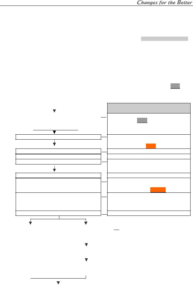
1.1.2. Flowchart
|
|
|
|
Start |
||||
|
|
|
|
|
|
|
|
|
|
|
|
|
|
|
|
|
|
1.2 Cube installation |
|
|
|
|
|
|||
1.2.5 Cube stacking |
|
1.2.6 Cube stacking |
||||||
(for |
Rear |
) |
|
(for |
Front |
) |
||
|
|
|
|
|
|
|
|
|
1.3Connecting
1.4Initial set up
1.4.2Dipswitch setting
1.4.3Picture outline adjustment
1.5System memory setting
1.5.1System set up
1.5.2Color balance adjustment
1.5.3Image set up
Major setting items
•Input board installation (optional)
•Unlocking (for XL21  )
)
•Control signal connection
•Image signal connection
•Internal cabling (for Front  )
)
•Operation mode (to advanced mode)
•Displaying internal test pattern
•6-axis adjustment
•Mirror adjustment
•LAMP POWER
•SYSTEM SYNC
•HOT EXCHANGE (for Changer )
)
•CSC
•GRADATION
•TARGET COLOR
•SENSOR
(When necessary)
|
1.6 Input memory setting |
|
|
1.7 |
Input memory setting |
|
• |
Input port selecting |
|
||||
|
(for the main input) |
|
|
(for the input board) |
|
• |
Automatic input signal scanning |
|
|||||
|
|
|
|
|
|
|
|
|
|
|
• |
H.POSITION, V.POSITION |
|
|
|
|
|
|
|
|
|
|
|
|
• |
FINE |
|
|
|
|
|
|
|
|
|
|
|
|
• |
AMP GAIN |
|
|
|
|
|
|
|
1.8 |
Display memory setting |
|
|
|
|
||
|
|
|
|
|
|
(for the input board) |
|
|
|
|
|||
|
|
|
|
|
|
|
|
|
|
|
|
|
|
|
|
|
|
|
|
|
|
|
|
|
|
|
|
|
|
|
|
1.9 |
Setting as daisy chain |
|
|
|
|
||||
|
|
|
|
|
|
connection (for the input |
|
|
|
|
|||
|
|
|
|
|
|
board) |
|
|
|
|
|||
|
|
|
|
|
|
|
|
|
|
|
|
|
|
|
|
|
|
|
|
|
|
|
|
|
|
|
|
|
|
|
|
|
|
|
|
|
|
|
|
|
|
|
|
|
|
Finish |
|
|
|
|
|
|
|
||
|
|
|
|
|
|
|
|
|
|
|
|
|
|
|
|
|
|
|
|
|
|
|
|
|
|
REV 2.4 |
|
5

1.2. Cube installation
1.2.1. Safety precaution
•This product requires a special installation to prevent falling or toppling. This should be done by installation specialists.
•Be sure to read this manual and the user’s manual for your safety before starting assembly or installation.
•Be sure to use supplied accessories for assembly or installation.
•Attach all the screws and fixtures specified in this manual securely.
•Reinforce the wall surface and floor so that it can support the total weights of the products for a long time and resist earthquakes, possible vibrations, and external forces.
•Ensure that the safety factor is more than 10 (or ensure that the total bolts can bear ten times the weight of products and the brackets).
•Do not use the product near a heater or in a humid, dusty or smoky location.
•Unless otherwise specified, do not install the product with its intakes, exhaust slots and ventilation holes blocked. The unit may overheat and cause a fire or breakdown.
•Be sure that a lighting or sunlight does not leak into the screens.
•Inspect the mounting fixings more than once in a year as needed.
1.2.2. Preparation
•Before installation, remove the desiccant(s) taped on the top of the product.
•Make sure that all of the following are supplied.
|
|
Supplied accessories (per unit) |
|
|
Q’ty |
|
|
Necessary tools |
|
|||||||||||||||||||||
|
1. |
Hexagon socket head bolt (M6) |
|
|
8 |
|
|
|
|
1. |
Allen wrench |
|
||||||||||||||||||
|
2. |
Flat washer (for M6) |
8 |
|
|
|
|
|
2mm, 2.5mm, 4mm, 5mm |
|
||||||||||||||||||||
|
3. |
Spring washer (for M6) |
8 |
|
|
|
|
2. |
Phillips screwdriver #0, #2 |
|
||||||||||||||||||||
|
4. |
Joint hole seal |
1 |
|
|
|
|
3. |
Level |
|
||||||||||||||||||||
|
5. |
Power cord (1.8m) for North America and Europe |
2 |
|
|
|
|
4. |
Stepladder |
|
||||||||||||||||||||
|
|
(in VS-50XL20U and VS-67XL20U) |
|
|
|
|
5. |
Spacer (for suitable screen |
|
|||||||||||||||||||||
|
|
|
|
|
|
|
|
|
|
|
||||||||||||||||||||
|
6. |
Control cable |
1 |
|
|
|
|
6. |
gaps) |
|
||||||||||||||||||||
|
7. |
User’s manual |
1 |
|
|
|
|
Wrench (for base stand level |
|
|||||||||||||||||||||
|
|
|
|
|
|
adjuster) |
|
|||||||||||||||||||||||
|
|
|
|
|
|
|
|
|
|
|
|
|
|
|
|
|
|
|
|
|
|
6 ( |
50” |
|
), |
|
|
|
||
|
|
|
|
|
|
|
|
|
|
|
|
|
|
|
|
|
|
|
|
|
|
|
|
|
|
|||||
|
8. |
Plastic cable tie (for |
Front |
) |
|
|
|
|
|
|
|
|
|
|
|
|
|
|||||||||||||
|
|
|
|
|
|
|
|
|
|
|
|
|
|
|
|
|
|
|||||||||||||
|
|
|
10 ( |
67” |
) |
|
|
|
|
|||||||||||||||||||||
|
|
|
|
|
|
|
|
|
|
|
|
|
|
|
|
|
|
|
|
|
|
|
|
|
|
|||||
|
|
|
|
|
|
|
|
Optional products |
|
|
|
|
|
|
|
|
|
Others |
|
|||||||||||
|
1. |
Wireless/wired remote control: R-XL50TX |
|
|
|
|
|
|
|
|
1. |
Base stand |
|
|||||||||||||||||
|
2. |
RGB input board: |
|
|
|
|
|
|
|
|
2. |
Base stand level adjuster |
|
|||||||||||||||||
|
|
VC-B50KA (for |
PH50 |
, |
XL50 |
), VC-B20KA (for |
PH50 |
, |
XL21 |
) |
|
3. |
Base stand level adjuster |
|
||||||||||||||||
|
|
|
|
|
|
|
|
|
|
|
|
|
|
|
|
|
|
|
|
|
|
|
|
|
|
|
|
|
fixing metal part |
|
|
3. |
Video input board: |
|
|
|
|
|
|
|
|
|
|
||||||||||||||||||
|
|
|
|
|
|
|
|
|
4. |
Wall fixing metal part |
|
|||||||||||||||||||
|
|
VC-B50KV (for |
PH50 |
, |
XL50 |
), VC-B20KV (for |
PH50 |
, |
XL21 |
) |
|
|
||||||||||||||||||
|
|
|
5. |
Anchor bolt |
|
|||||||||||||||||||||||||
|
4. |
Power cord (3m): |
|
|
|
|
|
|
|
|
|
|||||||||||||||||||
|
|
|
|
|
|
|
|
|
6. |
Hexagon socket head cap |
|
|||||||||||||||||||
|
|
JC-PC3MA (for North America) |
|
|
|
|
|
|
|
|
|
|||||||||||||||||||
|
|
|
|
|
|
|
|
|
|
|
screw (M6) |
|
||||||||||||||||||
|
|
JC-PC3ME (for Europe) |
|
|
|
|
|
|
|
|
|
|
||||||||||||||||||
|
|
|
|
|
|
|
|
|
|
|
|
|
||||||||||||||||||
|
|
JC-PC3MC (for China) |
|
|
|
|
|
|
|
|
|
|
|
|||||||||||||||||
|
5. |
External AC fan (for |
50” |
|
Single |
Front |
): |
|
|
|
|
|
|
|
|
|
|
|
|
|
||||||||||
|
|
JC-AF115R (for |
AC115V) |
|
|
|
|
|
|
|
|
|
|
|
|
|||||||||||||||
|
|
JC-AF230R (for AC230V) |
|
|
|
|
|
|
|
|
|
|
|
|||||||||||||||||
|
6. |
Motorized adjustment tool: S-AXL50E |
|
|
|
|
|
|
|
|
|
|
|
|||||||||||||||||
|
7. |
Spare lamp: |
|
|
|
|
|
|
|
|
|
|
|
|||||||||||||||||
|
|
S-PH50LA (for |
|
Changer |
) |
|
|
|
|
|
|
|
|
|
|
|
|
|
||||||||||||
|
|
S-XL50LA (for |
|
Single |
|
) |
|
|
|
|
|
|
|
|
|
|
|
|
|
|||||||||||
|
|
|
|
|
|
|
|
|
|
|
|
|
|
|
||||||||||||||||
|
8. |
Spare color wheel: |
|
|
|
|
|
|
|
|
|
|
|
|
|
|
|
|
|
|
||||||||||
|
|
S-PH50CW (for |
|
PH50 |
) |
|
|
|
|
|
|
|
|
|
|
|
|
|
||||||||||||
|
|
S-XL50CW (for |
XL50 |
), S-XL20CW (for |
XL21 |
) |
|
|
|
|
|
|
|
|
|
|
|
|||||||||||||
PH50, XL50, XL21 series Set-up and Installation Manual
6
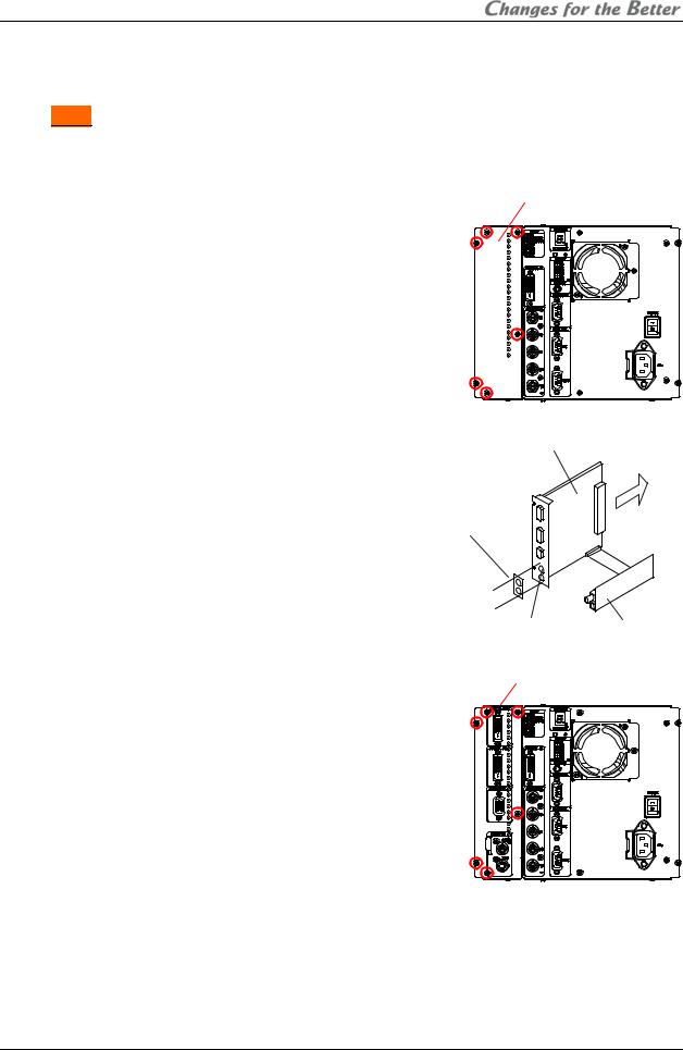
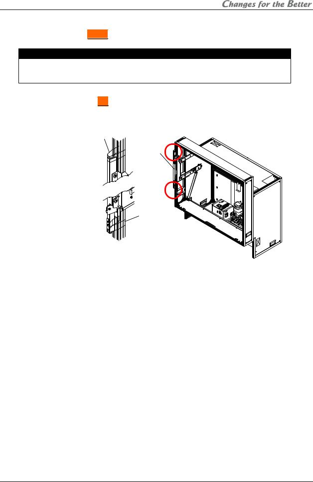
1.2.3. Input board installation (optional)
When using the optional input board, install it into the product according to the following steps.
In Front , a slot for the board is located inside the cube. Open the screen unit before installation according to the chapter 1.2.7 on page 21.
When you attach it, be sure to turn off the main power switch.
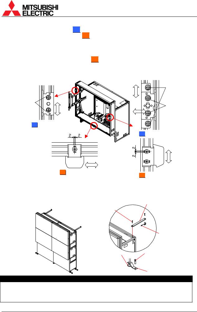
1.Remove a panel cover on the control panel by removing 6 screws at the positions shown in the figure.
Panel cover
2.When you use the video input board, attach it as right figure. Stick a supplied terminal name label on the RGB input board, and combine the boards with supplied 2 screws.
3.Firmly insert the input board into the board slot along guide rails till the end.
RGB input board |
|
2. Stick the supplied |
Insert |
|
|
terminal name label, |
|
and then combine |
|
the boards with 2 |
|
supplied screws. |
|
1. Remove 2 hole-stoppers. |
Video input board |
|
|
Input board |
|
4. Firmly fix the input board with the 6 screws that have been removed in the step 1.
REV 2.4
7
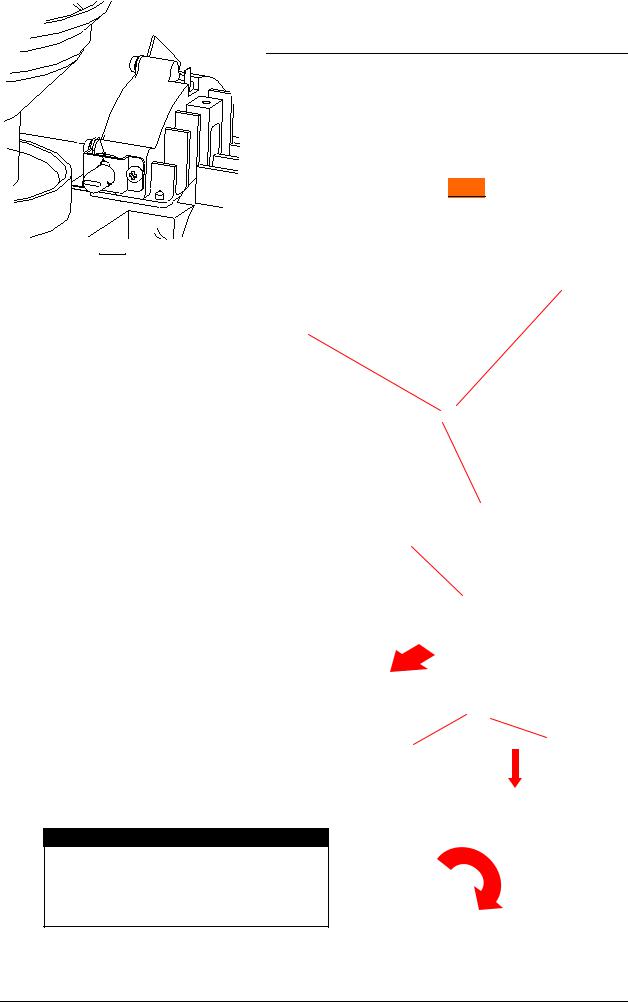
1.2.4. Unlocking (for XL21  )
)
Surely release following locks before turning on the main power switch. Turning on without releasing may cause damage.
1.2.4.1. Color wheel unlocking
The color wheel is located on the optical unit inside the cube. In Front , open the screen unit according to the chapter 1.2.7 on page 21 before unlocking. Turning on without unlocking may cause damage.
1. Make sure a key slot on the color wheel cushion faces the top as you begin the
procedure.
Key slot
Metal
Color wheel cushion
2. Pull the color wheel cushion till the flange hits |
Stopper |
||
the metal part. |
|
||
• For |
Changer |
, pliers are recommended to |
|
use since it is hard to access with fingers. |
|
||
Metal
Flange
3.Turn it 90 degrees clockwise.
Caution
Before shipment, be sure to lock the color wheel in the reverse order of unlocking (chapter 2.5.2, on page 85). Shipping the product without locking may cause breakage.
PH50, XL50, XL21 series Set-up and Installation Manual
8
1.2.4.2. Lamp cushion removing (for Changer )
)
Remove a lamp cushion before turning on the main power switch. Turning on without removing may cause smoking and catching fire.
•It should be remembered to lock the lamp cover after removing. If you neglect to lock it, the lamp changer may not work correctly.
Lamp cushion
Lock
Lamp cover
Caution
Before shipment, be sure to insert the cushion in the reverse order of removing (chapter 2.5.3, on page 85). Shipping the product without inserting may cause breakage.
REV 2.4
9
1.2.5. Cube stacking (for Rear  )
)
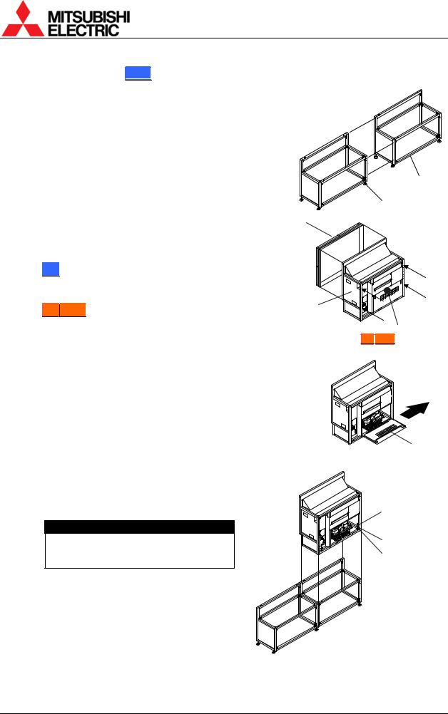
1.2.5.1. Assembling the base stands and cubes
1.Assemble base stands.
2.Adjust level adjusters to make the base stand both level and plumb by means of a spirit level.
Base stands
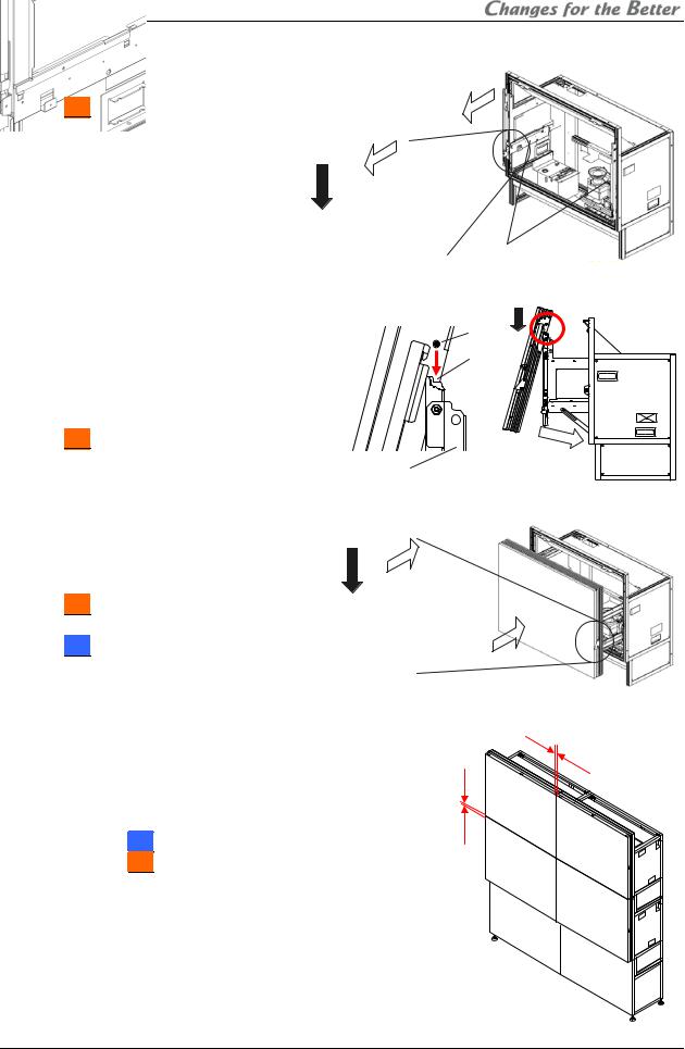
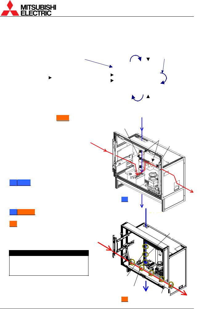
3.Loosen 4 screen-fixing screws per unit shown with arrow lines in the right figure with an Allen wrench (5 mm) to remove the screen units from all cubes to be installed. (This applies to 50” , which is supplied with the screen fitted).
4.67”PH50 : Turn a center screw in the lower door 90 degrees anti-clockwise to unlock with an Allen wrench (4mm).
5.Open the lower door 90 degrees by pushing down the handles. And then slide it to right to detach. The door cannot be detached other than 90 degrees opening position.
Level adjusters
Screen unit
Screen-fixing
screws
Cube unit
Center screw
(67”
 PH50
PH50 )
)
Lower door
6.Place a cube on the base stand.
7.Fix the cube at 4 points with supplied hexagon socket head bolts, spring washers and flat washers.
Caution
When holding up a cube, be careful not to put your hand between the cube and the base stand.
Hexagon socket head bolt
Spring washer
Flat washer
PH50, XL50, XL21 series Set-up and Installation Manual
10
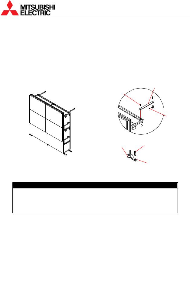
8.Place the next bottom row cube on the base stand and fix it in the same way.
9.Join right and left cubes at 4 points with supplied hexagon socket head bolts, spring washers and flat washers.
10.Place cubes for the upper row on the assembled units.
11.Fix them vertically and horizontally at 4 points each with supplied hexagon socket head bolts, spring washers and flat washers.
12.Stop up the holes on both sides with supplied joint hole seals, which holes are not used for a display wall.
Caution
To avoid units from falling, measure horizontal and vertical degrees with a level etc. to make sure the units are stably assembled.
1.2.5.2. Screen gap adjustment
1.Temporarily attach the screen units, which were detached in the previous step. (For
67-inch models, the screens were supplied |
1mm |
|
(2mm) |
||
separately). |
||
|
2.Put spacers between screens and adjust the screen gaps to be:
1 mm for 50” or
or
2 mm for 67” .
.
3.Tighten the 4 screen-fixing screws. Be careful not to tighten with an excessive torque (suggested torque: 3.9Nm).
Joint hole seals
1mm
(2mm)
REV 2.4
11
1.2.5.3. Fixing to the wall and floor
You don’t have to attach the lower door in this chapter since picture outlines have yet to be adjusted as explained in the next chapter.
After the picture outline adjustment, attach the door in the reverse order of detaching.
1.Attach floor-fixing brackets on 4 level adjusters below the base stand and fix them to the floor with anchor bolts.
2.Fix the upper back part of the display wall to the back wall with wall-fixing brackets as shown in the following figure.
Wall-fixing brackets
Hexagon socket head cap screws (M6)
Anchor bolts
Adjusters |
Anchor bolts |
|
Floor-fixing brackets
Caution
Make sure the whole set is assembled firmly and installed stably. To prevent the set from falling due to unpredictable events such as earthquakes and shocks, fix the set firmly to the wall and floor. Furthermore, carefully confirm the strength of the fixing area of the installation place (wall and floor). The wall and floor fixing method differs according to the number of assembled units.
PH50, XL50, XL21 series Set-up and Installation Manual
12
1.2.6. Cube stacking (for Front  )
)
Caution
Take heed of appropriate surrounding space for ventilation (except rear surface) such as not to pool the hot air on the top of the display walls so that the ambient temperature doesn’t exceed the product environmental requirements.
1.2.6.1. Tape peeling off (for 67” )
)
The screen-holding arms in both sides are taped at each end for transportation. Peel them off before installation.
Tape
Screenholding arm
Tape
REV 2.4
13
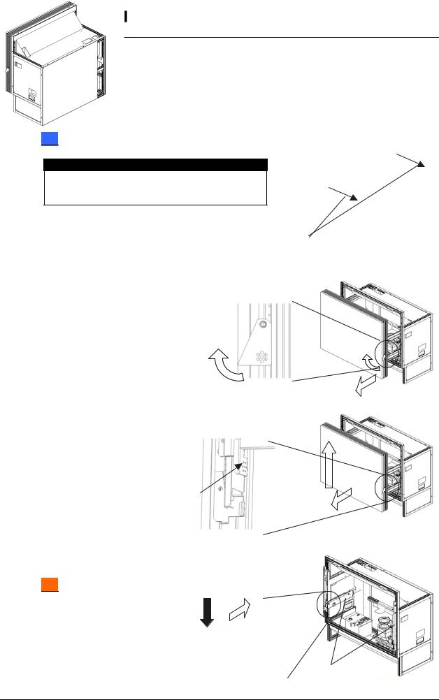
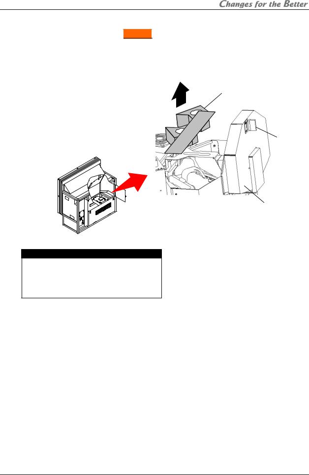
1.2.6.2. Screen detaching
For 50” which is supplied with the screen fitted, the screen unit should be detached before installation. (For 67”
 , the screens are provided separately.)
67” : Screen attaching/detaching work should be done by two or more people.
Be careful not to trap your fingers when you slide its arms during detaching/attaching work.
1.50” : Remove two screen-fixing bolts (M6 – 45mm,
gold hexagon socket). Caution
Before shipment, be sure to tighten the bolts (see chapter 2.5.4, on page 86). Shipping the product without tightening may cause breakage.
Screen-fixing
bolts
2.Pull screen-drawing handles in both sides to draw the screen till locked.
Screen-drawing handle
3.Lift up and detach the screen unit with pushing screen-detaching levers located inside the screen unit in
both sides. Be careful not to push the adjacent flip-up lock lever.
Push (Flip-up lock lever) 
Screen-detaching lever (inside the screen unit)
4.Press down the slide lock levers in both sides to unlock, and put back the screen-holding arms.
67” : The levers can be unlocked respectively.
Slide lock lever (Inside the arm) |
Screen-holding arm |
|
PH50, XL50, XL21 series Set-up and Installation Manual
14
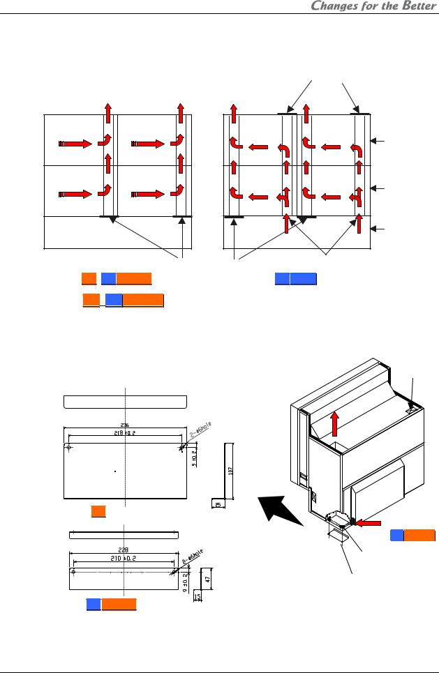
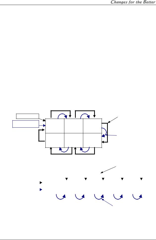
1.2.6.3. Ventilation
To ensure a proper airflow for cooling, you need to block some vents as the following figures.
|
|
|
|
|
|
Should be blocked |
|
Exhaust |
Exhaust |
Exhaust |
|
Exhaust |
|
Panel 1 |
|
Panel 2 |
|
Panel 1 |
|
Panel 2 |
|
|
|
|
|
|
Top row |
(From rear) |
(From rear) |
|
|
|
|
|
Panel 3 |
|
Panel 4 |
|
Panel 3 |
|
Panel 4 |
|
|
|
|
|
|
Bottom row |
(From rear) |
(From rear) |
|
|
|
|
|
|
|
|
|
|
|
Base stand |
|
|
|
|
|
Intake |
Intake |
|
|
Vents to be blocked |
Vents to be blocked |
External AC fans (occasional) |
||
|
|
|
|
|
|
|
For 67” |
, 50” Changer |
|
For |
50” Single |
||
|
|
|
Airflow concept |
|
|
|
1.2.6.3.1. |
For 67”, 50”Changer |
1.Block the vents in the bottom row. Prepare a cover material by yourself in reference to the figures below. The covers can be fixed with two self-tapping screws (nominal diameter: 4mm, length: 8 – 12mm) on the holes of the corner joint. Be sure this work is only for the cubes in
the bottom row.
Vent covers (example):
Material: aluminum or steel plate (thickness: 1mm)
Cable hole
Exhaust
For 67”
For 50”
 Changer
Intake
(from right side
in50” Changer) Vent cover 


Holes of corner joint
Two self-tapping screws (nominal diameter: 4mm, length: 8 – 12mm)
Unit [mm]
2.To keep dust out, seal the cable holes on the top of the display wall. Prepare a cover material by yourself. The size of the holes is 116.5mm x 63mm. Be sure this work is only for the cubes in the top row.
REV 2.4
15
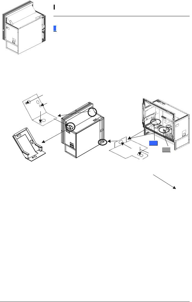
1.2.6.3.2.For 50”Single
According to circumstances, attach the optional external AC fans (JC-AF115R or JC-AF230R) on the intake vents in the bottom row (see “External AC fan attaching” on page 17).
•Prepare openings on base stands to ventilate.
•Keep enough base stand height not to inhale a coat of dust on a floor from the intake vents.
1.To block the bottom row, detach the bottom duct cover from inside the cube and attach it on the bottom of the duct. Be sure this work is only for the cubes in the bottom row.
2.To block the top row, remove the cushion unit on the top at first. Then detach the top duct cover from the top surface of the cube and attach it on the top of the duct. Be sure this work is only for the cubes in the top row.
Tighten removed 3 screws to attach.
Detaching
Tighten the duct screw Top duct cover to attach with duct
panel.
Detaching
XL50
Detaching
XL21
Cushion unit
Bottom duct cover
3.To keep dust out, seal the cable holes on the top of the display wall. Prepare a cover material by yourself. The size of the holes is 116.5mm x 63mm. Be sure this work is only for the cubes in the top row.
Tighten removed screw to attach.
Cable hole
PH50, XL50, XL21 series Set-up and Installation Manual
16
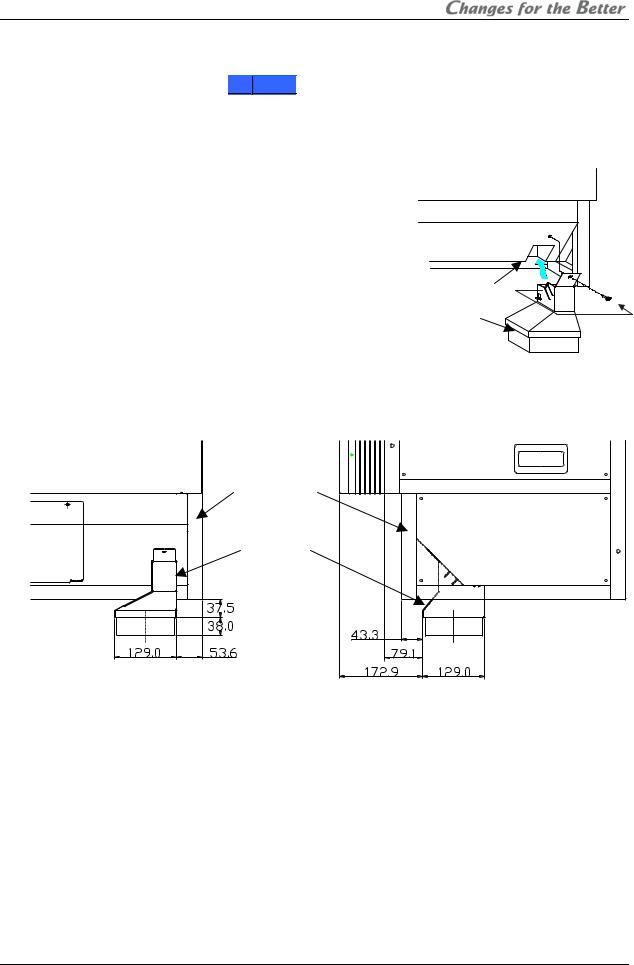
External AC fan attaching (occasional)
When 4-high configuration with 50”Single , attach the optional external AC fans (JC-AF115R or JC-AF230R) on intake vents. Even in 3-high configuration, attach the AC fans as well, when spaces are narrower than 50cm to the ceiling and 10cm to the wall behind. Narrow spaces tend to rise the cube internal heat. Be sure this work is only for the cubes in the bottom row.
1.Attach a suitable plug to the bare end of the power cord of the fan to correspond with an interface such as a terminal block or a power strip. 2-meter AC power cord is included in the fan.
2.Insert the fan into the intake vent till click.
3.Fix it to the lower part of cube with the screw supplied
with the fan. Note:
• To avoid injuries and shock hazards, do not carry External
electricity to the fan during this work. It must be done by qualified personnel.
AC fan
•Be sure to use the fan within the range of its power rating.
•The outline of the fan is shown below. Prepare a base stand which does not interfere with the fan.
Lower part of cube
External
AC fan
[Unit: mm]
Front view |
Side view |
REV 2.4
17
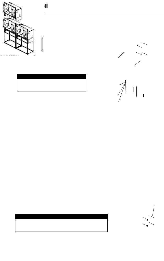
1.2.6.4. Assembling base stands and cubes
1.Assemble base stands.
2.Adjust level adjusters to make the base stand both level and plumb by means of a spirit level.
Base stands
Level adjusters
3.Place a cube on the base stand. Caution
Do not grip the screen-holding arms to lift up a cube cabinet. It may cause breakage.
4.Fix the cube at 4 points with supplied hexagon socket head bolts, spring washers and flat
Hexagon socket head bolt
Spring washer
washers. |
Flat washer |
|
|
|
Caution |
|
|
|
When holding up a cube, be careful not |
|
|
|
to put your hand between the cube and |
|
|
|
the base stand. |
|
|
|
|
|
|
|
|
|
|
5.Place the next bottom row cube on the base stand and fix it in the same way.
6.Join right and left cubes at 4 points with supplied hexagon socket head bolts, spring washers and flat washers.
7.Place cubes for the upper row on the assembled units.
8.Fix them vertically and horizontally at 4 points each with
supplied hexagon socket head bolts, spring washers and flat washers.
9. Stop up the holes on both sides with supplied joint hole |
Joint hole seals |
|
seals, which holes are not used for a display wall.
Caution
To avoid units from falling, measure horizontal and vertical degrees with a level etc. to make sure the units are stably assembled.
10.Run cables through the internal cabinets according to the chapter 1.3.3 on page 24 before attaching the screen unit.
PH50, XL50, XL21 series Set-up and Installation Manual
18
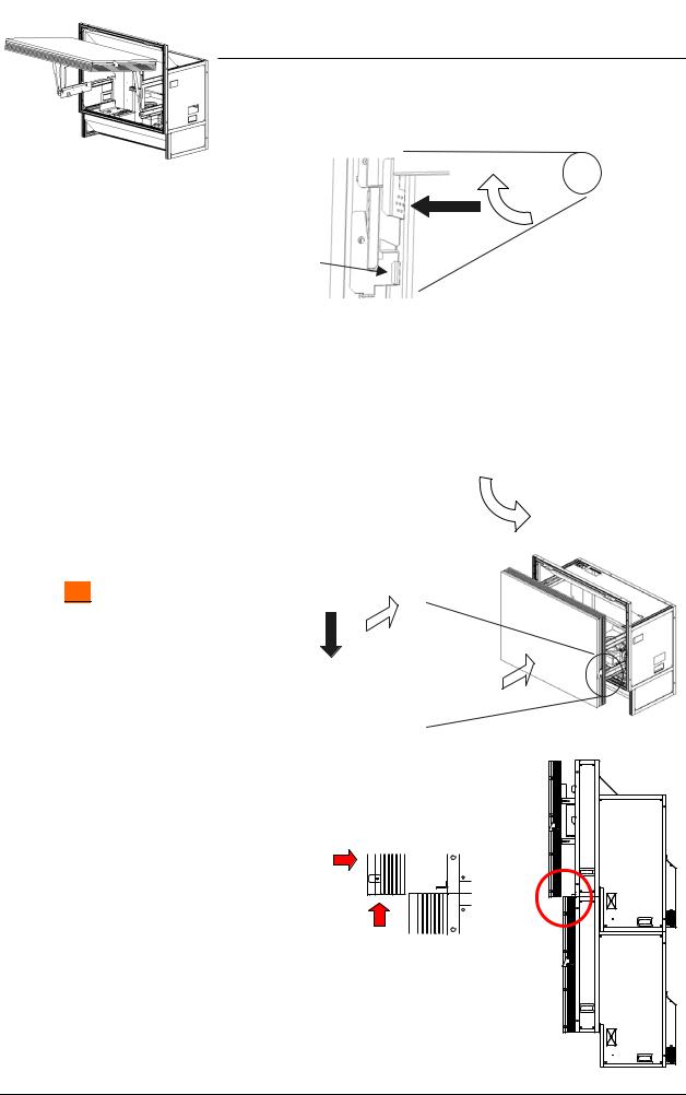
11.Press down the slide lock levers in both sides to unlock, and draw the screen-holding arms till locked.
67” : The levers can be unlocked respectively.
Screen-holding arm
Slide lock lever (Inside the arm)
12.Reinstall the screen unit in its original cabinet. Put the pins inside the screen unit on the retainers at the top of the screen-holding arms, following which make the screen upright. Make sure it will be locked securely.
67” : Screen attaching/detaching work should be done by two or more people.
Pin |
Retainer |
screen-holding arm
13.Press down the slide lock levers in both sides to unlock, and push the screen unit along the rail till the end.
67” : The levers can be unlocked respectively.
50” : You don’t have to tighten the removed two screen-fixing
bolts. |
Slide lock lever (Inside the arm) |
||
1.2.6.5. Screen gap adjustment |
|
|
|
This adjustment is normally unnecessary. |
2mm |
||
As needed, you can adjust the screen gaps. |
|||
(3mm) |
|||
1. Estimate a distance to move the screens so that the screen gaps will approximately be:
2 mm for 50” or
or
3 mm for 67” .
.
2.Open the screen units (chapter 1.2.7.1, on page 21).
2mm
(3mm)
REV 2.4
19
3.For horizontal adjustment: 50” : Loosen two screws in the right screen guide to adjust its horizontal position and fix them. 67”
 : Loosen the screw in the bottom screen guide to adjust its horizontal position and fix it. The screen guide has punch marks at the adjustable range (+/- 2mm) and its center.
4.For vertical adjustment: Loosen two screws each in the left and right screen guides to adjust
their vertical positions and fix them. 67” : The screen guides have the punch marks at the same position as described above.
5.Close the screen units (chapter 1.2.7.2, on page 22).
6.Check the screen gaps and repeat the steps until you get reasonable gaps.
|
For vertical |
|
adjustment |
For vertical |
|
adjustment |
For horizontal |
|
|
|
adjustment |
50” Left screen guide |
|
For horizontal |
adjustment |
67” Bottom screen guide |
1.2.6.6. Fixing to the wall and floor
50” Right screen guide
For vertical adjustment
67” Screen guide (both side)
1.Attach floor-fixing brackets on 4 level adjusters below the base stand and fix them to the floor with anchor bolts.
2.Fix the upper back part of the display wall to the back wall with wall-fixing brackets as shown
in the following figure.
Wall-fixing brackets
Hexagon socket head cap screws (M6)
Anchor bolts
Adjusters |
Anchor bolts |
|
Floor-fixing brackets
Caution
Make sure the whole set is assembled firmly and installed stably. To prevent the set from falling due to unpredictable events such as earthquakes and shocks, fix the set firmly to the wall and floor. Furthermore, carefully confirm the strength of the fixing area of the installation place (wall and floor). The wall and floor fixing method differs according to the number of the assembled units.
PH50, XL50, XL21 series Set-up and Installation Manual
20
1.2.7. Screen open/close (for Front  )
)
Cabling or lamp replacement, etc. requires opening the screen unit. Be careful not to trap your
fingers during the work.
The open/close should be performed on a one-by-one basis in a display wall so as not to shift the center of gravity much.
In particular, 67” may cause topple
down due to wide shifting of the center of gravity. When you open/close the screen units on stand-alone cubes without fixing to a base stand or other cubes, be sure to use the support base which is contained in the cube carton box.
1.2.7.1. Screen opening
Caution
About one-meter space in front of the screens is needed for the opening. Prior to work, make sure that there is no object such as steps in the working space.
Cube unit
 Screen unit Support base
1.50” : Make sure that the two screen-fixing bolts (M6 –
45mm, gold hexagon socket) have been removed.
Screen-fixing bolts
2.Pull the screen-drawing handles in both sides to draw the screen till locked.
Screen-drawing handle
REV 2.4
21
3.Pull up the bottom of the screen unit to rotate 90 degrees with pushing flip-up lock levers located inside the screen unit in both sides.
67” |
: The levers can be unlocked |
|
respectively. |
|
|
Be careful not to push the |
|
|
adjacent screen-detaching lever. |
Push |
|
|
(Screen-detaching lever) |
|
|
|
Flip-up lock lever (inside the screen unit) |
1.2.7.2. Screen closing
Be careful not to trap your fingers during the work.
1.Push down the bottom of the screen slowly till locked.
2.Press down the slide lock levers in both sides to unlock, and push the screen unit along the rail till the end.
67” : The levers can be unlocked respectively.
Slide lock lever (inside the arm)
Note:
Depending on the screen gap adjustment (chapter 1.2.6.5, on page 19), the screen unit may touch the top edge of the lower screen. In this case, slightly lift the upper screen to close without touching.
PH50, XL50, XL21 series Set-up and Installation Manual
22
1.3. Connecting
1.3.1. Control signal connection
An external controller such as a personal computer etc. can control cubes through RS-232 format communication. In the case of a display wall, connect the external controller to a MASTER cube set by dipswitch (chapter 1.4.2, on page 28) with RS-232 cross cable, and connect CONTROL IN and CONTROL OUT terminals between cubes with supplied control cables. Do not connect to a loop.
Allocating ID numbers by dipswitch, each cube can be controlled separately by one controller. Up to 64 cubes can be chained in one control line.
1.3.2. Image signal connection
Connect (an) image input source(s) with cubes adequately.
1.3.2.1. In the case of daisy chain
In the case of an enlarged image displaying with digital daisy chain connection, install the optional input boards (chapter 1.2.3, on page 7) and connect DIGITAL IN and DIGITAL OUT terminals between cubes with digital cables (DVI-D) that are supplied with the boards. The digital image signal can be chained up to 16 cubes.
In the case of 3 by 2
Video device
External controller
|
|
|
Supplied digital cables |
|
|
|
(6 pcs) |
ID 1 |
ID 2 |
ID 3 |
|
MASTER |
SLAVE |
SLAVE |
|
ID 4 |
ID 5 |
ID 6 |
Supplied control cables |
(5 pcs) |
|||
SLAVE |
SLAVE |
SLAVE |
|
In the case of 6 by 1
(In this case, an image signal cannot be connected to a loop.)
Supplied digital cables (5 pcs)
|
|
|
|
|
|
|
|
|
|
|
|
|
|
|
|
|
|
|
|
|
|
|
|
|
|
|
|
|
|
|
|
|
|
|
|
|
|
|
|
|
Video device |
|
|
ID 1 |
|
ID 2 |
|
ID 3 |
|
ID 4 |
|
ID 5 |
|
ID 6 |
|||||
|
|
|
|
|
|
|
|
||||||||||||
|
|
|
|
|
|
|
|
|
|||||||||||
External controller |
|
|
MASTER |
SLAVE |
SLAVE |
|
SLAVE |
SLAVE |
SLAVE |
||||||||||
|
|
||||||||||||||||||
|
|
|
|
|
|
|
|
|
|
|
|
|
|
|
|
|
|
|
|
|
|
|
|
|
|
|
|
|
|
|
|
|
|
|
|
|
|
|
|
Supplied control cables (5 pcs)
REV 2.4
23
1.3.2.2. For other than daisy chain
Connecting with a multiple-output device, an enlarged image can be displayed as well as daisy chain connection.
|
|
|
|
|
|
|
|
|
|
|
|
Supplied |
|
|
|
External controller |
|
|
|
|
|
||||
|
|
|
||||||||||
|
|
|
|
|
|
|
|
|
|
|
|
control cables |
|
|
|
|
|
|
|
|
|
ID 1 |
ID 2 |
||
|
|
|
|
|
|
|
|
|
|
|||
|
|
|
|
|
|
|
|
|
|
|||
|
|
|
|
Multiple-output |
|
|
|
|
MASTER |
SLAVE |
|
|
|
|
|
|
|
|
|
|
|
||||
|
|
|
|
device |
|
|
|
|
|
|
|
|
|
|
|
|
|
|
|
|
|
|
|
|
|
ID 3 |
ID 4 |
|
||||||||||
Input image |
|
|
|
|
|
|||||||
|
|
|
|
|
|
|||||||
|
|
|
|
|
|
|||||||
|
|
|
|
|
|
|
|
|
SLAVE |
SLAVE |
|
|
|
|
|
|
|
|
|
|
|
|
|
|
|
|
|
|
|
|
|
|
|
|
|
|
|
|
|
|
|
|
|
|
|
|
|
|
|
|
|
Connecting with a multiple-output device (example)
1.3.3. Internal cabling (for Front  )
)
Run cables through the holes located on both sides and top/bottom.
For the vertical cabling: Thread the supplied plastic cable ties through the holes in 3 mount bases to fix on the rear surface of the back panel, and fasten the cables with the ties.
For the horizontal cabling:
50”Single : Route the cables through the guide below the mirror and fasten them with supplied cable ties as appropriate not to shade picture images from the optical unit.
50”Changer : Run the cables through the cable guide behind the mirror.
67” : Thread the supplied cable ties through the holes in 5 mount bases to fix on the rear surface of the skirt part, and fasten the cables with the ties.
Caution
For the safety reason, do not allocate a power strip inside the cube cabinet. It is recommended to use the optional 3-meter power cord.
Mount bases
Horizontal cabling
For 50”
Horizontal cabling
Plastic cable ties
Mount bases (for horizontal)
For 67”
Vertical cabling
Plastic cable ties
Cable guide
 Vertical cabling
Mount bases (for vertical)
Skirt part
PH50, XL50, XL21 series Set-up and Installation Manual
24

1.4. |
|
Initial set up |
|
|
|
|
|
|
|
|
1.4.1. |
Menu operation |
|
|
|
|
|
|
|
||
1.4.1.1. Control button list |
|
|
|
|
|
|
||||
|
|
Remote |
In stand- |
In normal mode |
|
In advanced mode |
|
|||
|
|
Menu OFF |
Menu OFF |
Menu ON |
||||||
|
|
control |
by state |
Test pattern |
Test pattern |
Test pattern |
Test pattern |
Test pattern |
|
Test pattern |
|
|
|
|
|||||||
|
|
|
|
ON |
OFF |
ON |
OFF |
ON |
|
OFF |
|
|
POWER ON |
Turn on |
|
|
|
|
|
|
|
|
POWER OFF |
|
|
|
Turn off |
|
|
|
||
|
|
DISPLAY |
|
Status information |
Status information (Press-and-hold for detail information) |
|||||
|
|
PIC MUTE |
|
|
|
Picture mute |
|
|
Picture mute |
|
|
|
INPUT A |
|
|
|
Selective input signal list |
|
|||
|
|
MENU1 |
|
|
Input memory menu |
|
|
|||
|
|
|
|
|
|
Display memory menu |
|
|
|
|
|
|
MENU2 |
|
|
(Press-and-hold for system |
|
|
|||
|
|
|
|
|
|
memory menu) |
|
|
|
|
|
|
MEM LIST |
|
|
Input memory and display memory list |
|||||
|
|
R |
|
|
R raster on/off |
R input on/off |
R raster on/off |
|
R input on/off |
|
|
|
G |
|
|
G raster on/off |
G input on/off |
G raster on/off |
|
G input on/off |
|
|
|
B |
|
|
B raster on/off |
B input on/off |
B raster on/off |
|
B input on/off |
|
|
|
TEST |
|
|
Test pattern on – pattern rounding – test pattern off |
|||||
|
|
FUNC |
|
|
|
Remote ID setting mode on/off |
|
|||
|
|
NORMAL |
|
Normal mode/advanced mode switching |
Initialize |
|||||
|
|
ESC |
|
|
|
Cancel, back or test pattern off, etc. |
|
|||
|
|
ENTER |
|
|
|
Define |
|
|||
|
|
UP |
|
|
|
|
Menu option and cursor up |
|||
|
|
DOWN |
|
|
|
|
Menu option and cursor down |
|||
|
|
LEFT |
|
|
|
|
Value down |
|||
|
|
RIGHT |
|
|
|
|
Value up |
|||
|
|
Number |
|
|
Display |
memory calling |
|
|
|
|
REV 2.4
1.4.1.2. Operation mode
This product has two operation modes: “normal mode” and “advanced mode”. Use the normal mode in usual operation. Switch to the advanced mode when you set up or adjust the product. Two modes can be switched by [NORMAL] button when there is no adjustment menu on screen.
1.4.1.2.1.Normal mode
The normal mode allows you to turn off the power by [POWER] button, to display status information by [DISPLAY] button, to change the operation mode by [NORMAL] button and to call a display memory by number buttons.
Adjustment menus cannot be called in the normal mode.
1.4.1.2.2. Advanced mode |
|
|
|
|
|
|
|
|
|
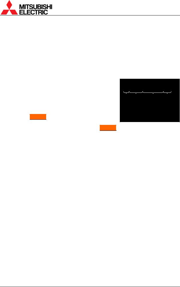
In advanced mode, status information appears on screen as |
|
|
|
|
|
! ANALOG NO SIGNAL |
ID01 |
|
|
described in right figure. |
|
|
||
|
|
|
|
|
1. Status display: |
Status Input port Comment |
Set ID |
||
•“!” mark appears when values in a menu are changed. It is also displayed when a value is automatically changed by internal process.
•In Changer , “ ” mark appears when the status of a spare lamp is other than “NEW”.
•During lamp position auto calibration (for Changer ) and initial sensor value obtaining, the operating status is noticed with figures such as “3”, “4” or “7”. When the function has worked correctly, it disappears after 5-minute displaying.
2.Input port: Displaying current input port.
3.Comment:
•“NO SIGNAL” is displayed when any image signal is not input.
•“TEST *” is displayed during internal test patterns displaying.
•“MUTE” is displayed during picture mute.
4.Set ID: Displaying a set ID.
PH50, XL50, XL21 series Set-up and Installation Manual
26

1.4.1.3. Basic menu operation
Adjustments should be conducted with the remote control in advanced mode. (You can also use the adjustment software, “Wallaby” (chapter 4, on page 99)).
•[POWER ON] button: To turn on after main power switch on.
•[MENU1] button: To display the input memory menus.
•[MENU2] button: To display the display memory menus while the input board is attached.
•[MENU2] button (press and hold): To display the system memory menus.
•Up/down button: To select menu items.
•[ENTER] button: To enter each adjusting menu. Some items indicate the lower menu layer.
•Left/right button: To change an adjusting value.
•[ESC] button: To exit menus.
•[NORMAL] button: To reset an adjusting value. In reply to appeared “RESET OK?” message, press [ENTER] button. You can exit the menu without resetting by [ESC] button.
[NORMAL] button also executes automatic input signal scanning during input memory menus displaying.
•[FUNC] button: Remote ID setting (chapter 1.4.1.4).
•[TEST] button: To display test patterns (chapter 3.3, on page 91). Even while any menus are displayed on screen, the test patterns on/off and selecting are available.
•[R][G][B] buttons: To switch muting/displaying of primary colors. It works regardless of remote ID setting.
Press-and-hold the button can always display the selected color. This function is helpful when you display the same color across a display wall, which mixes color displaying/muted cubes. Just pressing may unintentionally mute the color in other cubes.
•Number buttons: To call a display memory directly with 3-digit number while there is no menu on screen. For instance, press 001 to call the display memory 1.
•[DISPLAY] button: To show status information.
LAMP TIMER |
99999H |
Lamp operating time |
! ANALOG |
ID01 |
|
|||
INPUT |
ANALOG |
Input port |
F/W VER |
P01.50A |
Firmware version |
|||
SYSTEM ID |
01 |
Set ID |
H/W VER |
12.19 |
FPGA version |
|||
|
|
|
|
|
|
SET TIMER |
99999H |
Set operating time |
LAMP A NEW |
BUSY |
|
|
|
|
MASTER |
|
Master/slave setting |
LAMP B USED |
STANDBY |
Lamp status |
L.SENSOR |
125 |
Luminous sensor value |
|||
NO SIGNAL |
|
|||||||
|
Comment |
|||||||
|
|
|
|
|
||||
|
|
(In |
Changer |
|
) |
|
|
|
|
|
|
|
|
|
|||
|
|
|
|
|
|
|
||
Status information ([DISPLAY] button) |
|
|
|
|
Detail status information |
|
||
|
|
|
|
|
|
([DISPLAY] button press-and-hold) |
|
|
1.4.1.4. Remote ID
Remote ID is used to operate remote control toward a specified screen in a display wall. Even while any menus are displayed on screen, remote ID can be switched.
Specify a set ID by [FUNC] button and 2-digit number in advanced mode, which ID has been set in the dipswitch. When you control only ID=1 cube, press [FUNC]+[0]+[1]. It can be also selected by left/right button after the [FUNC] button. And then press [ENTER] button to confirm.
Pressing [FUNC]+[0]+[0] buttons enable remote control toward all cubes.
REV 2.4
27
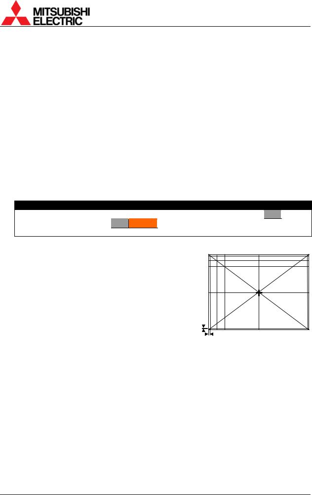
1.4.2. Dipswitch setting
Before turning on the main power switch, set the dipswitch correctly according to a system configuration (see “1.3 Connecting” on page 23). The set ID can be set up to 64 (see “1.5.1.14 EXTENDED ID” on page 41). Be sure to turn off the main power switch if you change the setting in the middle of the operation. Turning on the main power switch will renew the setting.
OFF |
|
|
|
ON |
|
|
|
|
|
|
|
|
|
|
|
|||
1 |
|
|
|
|
|
RC |
|
No. |
|
|
Name |
|
|
Function |
|
|
Initial |
|
|
|
|
|
|
|
|
|
|
|
|
|
setup |
|
|||||
2 |
|
|
|
|
|
RESERVED |
|
|
|
|
|
|
|
|
|
|
|
|
|
|
|
|
|
|
1 |
|
|
RC |
|
|
Enabling remote control (ON: enabled, OFF: disabled) |
|
|
ON |
|
||
|
|
|
|
|
|
|
|
|
|
|
|
|
||||||
3 |
|
|
|
|
|
MASTER |
|
|
|
|
|
|
|
|
|
|
|
|
|
|
2 |
|
RESERVED |
|
Normally ON. |
|
|
ON |
|
||||||||
|
|
|
|
|
|
|
|
|
|
|
||||||||
4 |
|
|
|
|
|
ID5 |
|
3 |
|
MASTER |
|
MASTER/SLAVE setting (ON: MASTER, OFF: SLAVE) |
|
|
ON |
|
||
|
|
|
|
|
|
|
|
|
|
|
||||||||
5 |
|
|
|
|
|
ID4 |
|
4 |
|
|
ID5 |
|
|
Designating set ID number (1 to 32) (ON: 1, OFF: 0) |
|
|
OFF |
|
|
|
|
|
|
|
|
|
|
|
|
|
|
||||||
6 |
|
|
|
|
|
ID3 |
|
5 |
|
|
ID4 |
|
|
ID No.=1×(ID1)+2×(ID2)+4×(ID3)+8×(ID4)+16×(ID5) |
|
|
OFF |
|
|
|
|
|
|
|
|
|
|
|
|
|
|
||||||
7 |
|
|
|
|
|
|
|
|
|
|
|
|
|
Example: |
|
|
|
|
|
|
|
|
|
ID2 |
|
6 |
|
|
ID3 |
|
|
|
|
OFF |
|
||
|
|
|
|
|
|
|
|
|
|
|
|
|
||||||
8 |
|
|
|
|
|
|
|
|
|
|
|
|
|
ID No.=1: ID1=ON, ID2, ID3, ID4 and ID5=OFF |
|
|
|
|
|
|
|
|
|
ID1 |
|
7 |
|
|
ID2 |
|
|
|
|
OFF |
|
||
|
|
|
|
|
|
|
|
|
|
|
|
|
||||||
|
|
|
|
|
|
|
|
|
|
|
|
|
|
ID No.=32 :ID1, 2, 3, 4 and 5=OFF |
|
|
|
|
|
|
|
|
|
|
|
|
8 |
|
|
ID1 |
|
|
|
|
ON |
|
|
|
|
|
|
|
|
|
|
|
|
|
|
|
|
|
|
|
|
|
1.4.3. |
Picture outline adjustment |
|
|
|
|
|
|
|
||||||||||
Caution
Before turning on, make sure again that the color wheel has been unlocked for XL21 (chapter 1.2.4.1, on page 8) and, for XL21Changer
 , the lamp cushion has been removed (chapter 1.2.4.2, on page 9).
1.4.3.1. Displaying internal test pattern
Display the internal crosshatch pattern for picture outline adjustment by pressing [TEST] button twice in advanced mode.
Adjust to align the outermost lines with screen edges.
There are another adjustment lines for over-scan inside the outermost lines. When OVERLAP setting (chapter 1.5.1.6, on page 38) is ON, adjust the picture outline so that these lines fit the screen edges.
Adjustment lines for over-scan
PH50, XL50, XL21 series Set-up and Installation Manual
28
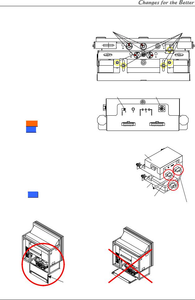
1.4.3.2.6-axis adjustment
1.4.3.2.1.Release the lock screws Before 6-axis adjustment, release locks in the adjuster. Loosen 4 locking screws with an Allen wrench (2mm) and 5 fixing screws with an Allen wrench (4mm).
4 locking screws |
5 fixing screws |
1.4.3.2.2.When adjusting with motorized adjustment tool, S-AXL50E
Attaching |
Slide switch |
Rotary Dial |
1.Set the rotary dial in the upper unit of the adjustment tool according to
the product (chapter 3.8.4.2, |
on |
OPE |
RESET |
POWER |
0:FRONT |
page 97). The initial setting is 0. |
|
FACTORY |
|
|
9:TEST |
|
|
|
ERROR FW-EN 1:REAR |
||
•Front : Set it 0.
•Rear : Set it 1.
2.Make sure the slide switch is set OPE (right side).
3.Connect the upper and lower units with a supplied
unit-connecting cable. |
Upper unit |
|
4.Connect a supplied cube-connecting cable with upper
unit.
5.Open the screen (chapter 1.2.7.1, on page 21) or rear panel to access the 6-axis adjuster.
Note: |
Lower unit |
|
For Rear, open the rear panel 180 degrees or |
Cube-connecting cable |
|
remove it to perform the adjustment. Adjustment with |
||
Unit-connecting cable |
||
half-open panel may cause breakage due to |
||
|
||
interference with the adjustment tool. |
|
Rear panel
REV 2.4
29

6.Make sure that latches on the units are released before the attaching the units.
7.Attach the units on the adjuster in order of the lower and upper unit.
8.Push the two latches each till click to fix the units.
Latch
Release Lock
Latches |
Latches |
|
Upper unit |
||
Lower unit |
9.Connect the other end of the cube-connecting cable with a connector inside the cube as following figures. The cable can be connected under operating conditions.
For |
Front |
For |
Rear |
Connector (in the circuit box)
10. Front : Close the screen (chapter 1.2.7.2, on page 22).
PH50, XL50, XL21 series Set-up and Installation Manual
30
Loading...