


Projection Television Models
WS-55859, WS-55909,
WS-65869, WS-65909,
and WS-73909
|
|
T |
|
|
US |
|
J |
|
D |
|
|
A |
|
|
|
|
T |
|
C |
|
E |
|
|
N |
|
|
N |
|
|
O |
|
|
C |
|
|
®
visit our website at
w w w.
 m i
m i
 t s u b i
 s h i
s h i
 -
-
 t v. c o m
CAUTION
RISK OF ELECTRIC SHOCK
DO NOT OPEN
CAUTION: TO REDUCE THE RISK OF ELECTRIC SHOCK, DO NOT REMOVE COVER (OR BACK).
NO USER SERVICEABLE PARTS INSIDE.
REFER SERVICING TO QUALIFIED SERVICE PERSONNEL.
The lightning flash with arrowhead symbol within an equilateral triangle is intended to alert the user of the presence of uninsulated “dangerous voltage” within the product’s enclosure that may be sufficient magnitude to constitute a risk of electric shock.
The exclamation point within an equilateral triangle is intended to alert the user to the presence of important operating and maintenance (servicing) instructions in the literature accompanying the appliance.
Warning: To avoid permanently imprinting a fixed image onto your TV screen, please do not display the same stationary images on the screen for more that 15% of your total TV viewing in one week. Examples of stationary images are letterbox top/bottom bars from DVD disc or other video sources, side bars when showing standard TV pictures on widescreen TVs, stock market reports, video game patterns, station logos, web sites or stationary computer images. Such patterns can unevenly age the picture tubes causing permanent damage to the TV. Please see pages 25 and 70 for a detailed explanation.
Note: This equipment has been tested and found to comply with the limits for a Class B digital device, pursuant to part 15 of the FCC Rules. These limits are designed to provide reasonable protection against harmful interference in a residential installation. This equipment generates, uses and can radiate radio frequency energy and, if not installed and used in accordance with the instructions, may cause harmful interference to radio communications. However, there is no guarantee that interference will not occur in a particular installation. If this equipment does cause harmful interference to radio or television reception, which can be determined by turning the equipment off and on, the user is encouraged to try to correct the interference by one or more of the following measures:
•Reorient or relocate the receiving antenna.
•Increase the separation between the equipment and the receiver.
•Connect the equipment into an outlet on a circuit different from that to which the receiver is connected.
•Consult the dealer or an experienced radio/TV technician for help.
CAUTION: To assure continued FCC compliance, the user must use a shielded video interface cable with bounded ferrite cores, when using the VGA input.
Changes or modifications not expressly approved by Mitsubishi could void the user’s authority to operate this equipment.
WARNING:
TO REDUCE THE RISK OF FIRE OR ELECTRIC SHOCK, DO NOT EXPOSE THIS APPLIANCE TO RAIN OR MOISTURE.
CAUTION:
TO PREVENT ELECTRIC SHOCK, MATCH WIDE BLADE OF PLUG TO WIDE SLOT, FULLY INSERT.
NOTE TO CATV SYSTEM INSTALLER:
THIS REMINDER IS PROVIDED TO CALL THE CATV SYSTEM INSTALLER’S ATTENTION TO ARTICLE 820-40 OF THE NEC THAT PROVIDES GUIDELINES FOR THE PROPER GROUNDING AND, IN PARTICULAR, SPECIFIES THAT THE CABLE GROUND SHALL BE CONNECTED TO THE GROUNDING SYSTEM OF THE BUILDING, AS CLOSE TO THE POINT OF CABLE ENTRY AS PRACTICAL.
Table of Contents
IMPORTANT SAFEGUARDS ............................................................................ |
4-5 |
||
T |
|
|
|
|
Thank You Letter ............................................................................................................................................... |
8 |
|
H |
|
|
|
A Y |
Unpacking Your New TV................................................................................................................................... |
9 |
|
N O |
Special Features ............................................................................................................................................... |
9 |
|
K U |
|
|
|
|
Front Control Panel Functions ...................................................................................................................... |
12 |
|
I |
Back Panel Functions..................................................................................................................................... |
13 |
|
N Installation Con gur at ions & Ne t Co mma nd™S e t up ................................................................................. |
15 |
||
S NetCommand™ Supported Devices ............................................................................................................. |
16 |
||
T Connecting to Your New Mitsubishi Bigscreen: |
|
||
|
Antenna or Wall Outlet Cable for Digital Broadcasts............................................................................ |
17 |
|
A |
|
|
|
|
Analog Antenna, Wall Outlet Cable, or Cable Box ................................................................................ |
18 |
|
L |
Analog VCR ............................................................................................................................................... |
19 |
|
L |
A/V |
Receiver........................................................................................................................................ |
20 |
A |
DVD Player or S-Video VCR or Satellite Receiver ................................................................................. |
21 |
|
T |
External DTV Receiver ....................................................................................................................... |
22-23 |
|
I |
Computer with a VGA Monitor Output .................................................................................................... |
24 |
|
|
IR-Home Theater Control and IR-Repeater ............................................................................................ |
24 |
|
O |
IMPORTANT NOTES ....................................................................................................................................... |
25 |
|
N |
NetCommand™ Setup .............................................................................................................................. |
26-35 |
|
|
|
on-screen menu system ................................................................................................................ |
38 |
|
Device Selection Menu............................................................................................................................. |
39 |
|
|
PIP Selection Menu................................................................................................................................... |
40 |
|
|
Menu Screens (Overview) ................................................................................................................... |
41-42 |
|
|
Setup Menu: Edit Setup and Icon Position ............................................................................................ |
43 |
|
|
Setup Menu: Convergence ...................................................................................................................... |
44 |
|
S |
Setup Menu: Advanced Convergence, Transport Menu and Language ............................................. |
45 |
|
|
Antenna Menu: Antenna, Memorize Channels, Memory and Name.................................................... |
46 |
|
E |
|
|
|
|
Antenna Menu: Super Quick View™ (SQV™) ........................................................................................ |
47 |
|
T |
|
|
|
|
Clock Menu: Auto or Manual Clock Setting ........................................................................................... |
48 |
|
U |
Captions Menu: Closed Captions ........................................................................................................... |
49 |
|
P |
V-Chip Menu: Passcode........................................................................................................................... |
50 |
|
|
V-Chip Menu: V-Chip ................................................................................................................................ |
51 |
|
|
V-Chip Menu: Lock By Time and Front Button Lock ............................................................................ |
52 |
|
|
Timer Menu: Setting The Timer............................................................................................................... |
53 |
|
|
A/V Settings Menu: A/V Memory Reset, Video Mute, Black Enhancement, and A/V Settings ........ |
54 |
|
|
A/V Settings Menu: TV Speakers............................................................................................................ |
55 |
|
|
A/V Setting Descriptions ................................................................................................................... |
56-57 |
|
O Remote Control Functions ....................................................................................................................... |
60-69 |
||
P |
Overview .................................................................................................................................................... |
60 |
|
E |
Care and Operation .................................................................................................................................. |
61 |
|
|
Channel Selection and Sleep Timer........................................................................................................ |
62 |
|
R |
|
|
|
|
Operation of PIP and POP.................................................................................................................. |
62-63 |
|
A |
|
|
|
|
Display Formats .................................................................................................................................. |
64-65 |
|
T |
Programming the Remote Control to Control NetCommand™ A/V Products ................................... |
66 |
|
I |
Programming the Remote Control to Control Non-NetCommand™ A/V Products ..................... |
67-68 |
|
O |
Special Functions ..................................................................................................................................... |
69 |
|
N IMPORTANT NOTES ...................................................................................................................................... |
70 |
||
Appendix A: Bypassing the V-Chip Lock ........................................................................................................... |
71 |
||
Appendix B: Input Connection Compatibility .................................................................................................... |
73 |
||
Appendix C: Remote Control Programing Codes ............................................................................................. |
74 |
||
Appendix D: Cleaning and Service ................................................................................................................ |
75-76 |
||
Appendix E: Diamond Shield Instructions .................................................................................................... |
77-78 |
||
Appendix F: Cabinet Separation ................................................................................................................... |
79-80 |
||
Appendix G: Troubleshooting ........................................................................................................................ |
81-82 |
||
Index ................................................................................................................................................................. |
|
83-84 |
|
Mitsubishi Projection TV Limited Warranty ....................................................................................................... |
85 |
||
Contents of Table
3
Important Safeguards
IMPORTANT SAFEGUARDS
Please read the following safeguards for your TV and retain for future reference. Always follow all warnings and instructions marked on the television.
1.Read, Retain and Follow All Instructions
Read all safety and operating instructions before operating the TV. Retain the safety and operating instructions for future reference. Follow all operating and use instructions.
2.Heed Warnings
Adhere to all warnings on the appliance and in the operating instructions.
3.Cleaning
Unplug the TV from the wall outlet before cleaning. Do not use liquid, abrasive, or aerosol cleaners. Cleaners can permanently damage the cabinet and screen. Use a lightly dampened cloth for cleaning.
4.Attachments and Equipment
Never add any attachments and/or equipment without approval of the manufacturer as such additions may
result in the risk of re, el ect ricshock or ot her per sonal inj ur y.
5.Water and Moisture
Do not use the TV where contact with or immersion in water is possible. Do not use near bath tubs, wash bowls, kitchen sinks, laundry tubs, swimming pools, etc.
6.Accessories
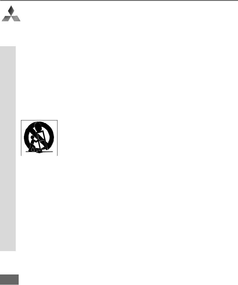
Do not place the TV on an unstable cart, stand, tripod, or table. The TV may fall, causing serious injury to a child or adult and serious damage to the TV. Use only with a cart, stand, tripod, bracket, or table recommended by the manufacturer, or sold with the TV. Any mounting of the TV should follow the manufacturer’s instructions, and should use mounting accessories recommended by the manufacturer.
An appliance and cart combination should be moved with care. Quick stops, excessive force, and uneven surfaces may cause the appliance and cart combination to overturn.
7.Ventilation
Slots and openings in the cabinet are provided for ventilation and to ensure reliable operation of the TV and to protect it from overheating. Do not block these openings or allow them to be obstructed by placing the TV on a bed, sofa, rug, or other similar surface. Nor should it be placed over a radiator or heat register. If the TV is to be placed in a rack or bookcase, ensure that there is adequate ventilation and that the manufacturer’s instructions have been adhered to.
8.Power Source
This TV should be operated only from the type of power source indicated on the marking label. If you are not sure of the type of power supplied to your home, consult your appliance dealer or local power company.
9. Grounding or Polarization
This TV is equipped with a polarized alternating current line plug having one blade wider than the other. This plug will t int ot he powe r out let onl yone wa y. If you ar e unabl et oi nser t the pl ug f ul lyi nt ot he out let , try reversing the plug. If the plug should still fail to t, cont act your el ect ric an t or epl ace your obsol et eout let . Do not defeat the safety purpose of the polarized plug.
10.Power-Cord Protection
Power-supply cords should be routed so that they are not likely to be walked on or pinched by items placed upon or against them, paying particular attention to cords at plugs, convenience receptacles, and the point where they exit from the TV.
11.Lightning
For added protection for this TV during a lightning storm, or when it is left unattended and unused for long periods of time, unplug it from the wall outlet and disconnect the antenna or cable system. This will prevent damage to the TV due to lightning and power-line surges.
4
IMPORTANT SAFEGUARDS Continued
12.Power Lines
An outside antenna system should not be located in the vicinity of overhead power lines or other electric light or power circuits, or where it can fall into such power lines or circuits. When installing an outside antenna system, extreme care should be taken to keep from touching such power lines or circuits as contact with them might be fatal.
13.Overloading
Do not overload wall outlets and extension cords as this can result in a risk of re or el ect ricshock.
14.Object and Liquid Entry
Never push objects of any kind into this TV through openings as they may touch dangerous voltage points or
short-out parts that could result in re or el ect ricshock. Ne ver spi ll liqui dof any ki nd on or int ot he TV.
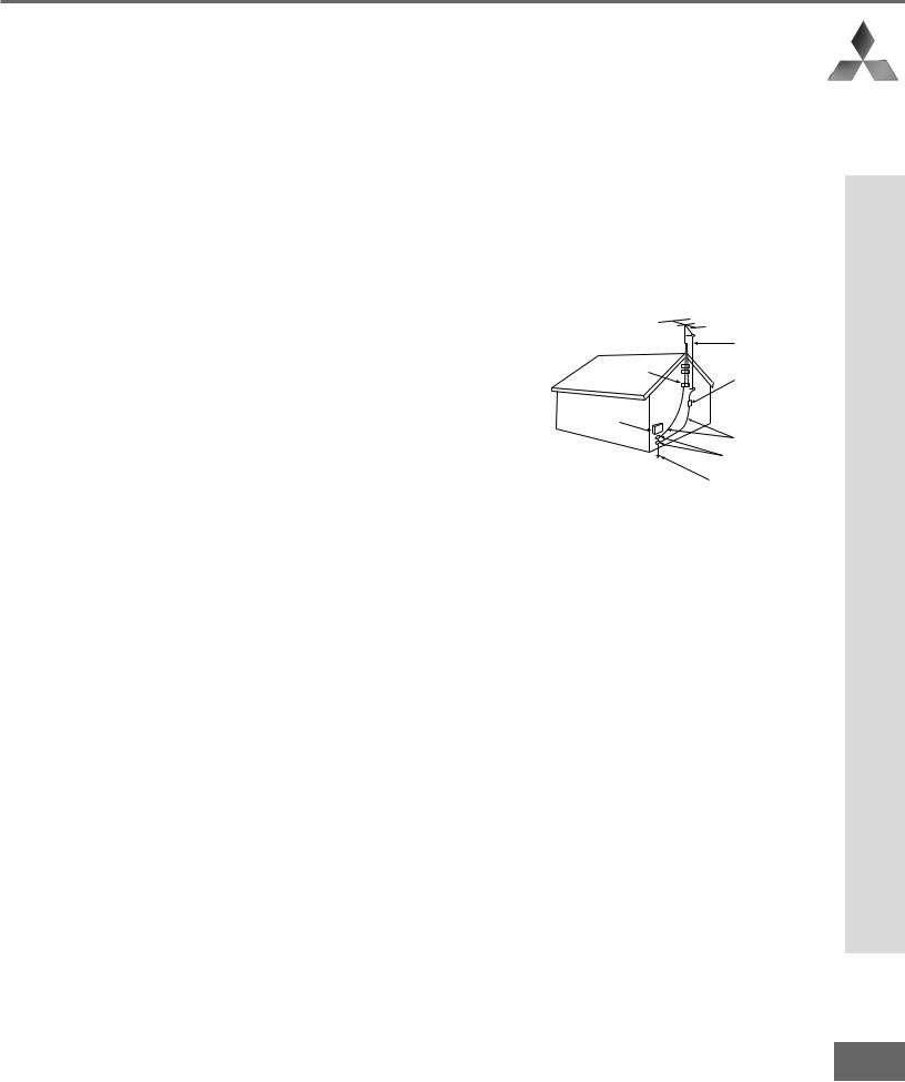
15.Outdoor Antenna Grounding
If an outside antenna or cable system is connected to the TV, be sure the antenna or cable system is grounded so as to provide some protection against voltage surges and built-up static charges.
Section 810 of the National Electric Code, ANSI/NFPA No. 70-1984, provides information with respect to proper grounding of the mast and supporting structure, grounding of the lead in wire to an antenna discharge unit, size of grounding conductors, location of antenna discharge unit, connection to grounding electrodes, and requirements for the grounding electrode.
EXAMPLE OF ANTENNA GROUNDING
|
ANTENNA |
|
|
LEAD IN WIRE |
|
GROUND CLAMP |
|
|
|
ANTENNA |
|
|
DISCHARGE UNIT |
|
ELECTRIC |
(NEC SECTION 810-20) |
|
|
||
SERVICE |
GROUNDING |
|
EQUIPMENT |
||
CONDUCTORS |
||
|
||
|
(NEC SECTION 810-21) |
|
|
GROUND CLAMPS |
|
|
POWER SERVICE GROUNDING |
|
|
ELECTRODE SYSTEM |
|
NEC — NATIONAL ELECTRICAL CODE (NEC ART 250 PART H) |
||
16.Servicing
Do not attempt to service this TV yourself as opening or removing covers may expose you to dangerous voltage or other hazards. Refer all servicing to quali ed ser vi ce per sonnel .
17.Damage Requiring Service
Unplug the TV from the wall outlet and refer servicing to quali ed ser vi ce per sonnel under the f ol lowi ng conditions:
(a)When the power-supply cord or plug is damaged.
(b)If liquid has been spilled, or objects have fallen into the TV.
(c)If the TV has been exposed to rain or water.
(d)If the TV does not operate normally by following the operating instructions, adjust only those controls that are covered by the operating instructions as an improper adjustment of other controls may result in damage and will often require extensive work by a quali ed t echni ci an t or est or e t he TV t oi ts nor ma l oper at ion.
(e)If the TV has been dropped or the cabinet has been damaged.
(f)When the TV exhibits a distinct change in performance - this indicates a need for service.
18.Replacement Parts
When replacement parts are required, be sure the service technician has used replacement parts speci ed by the manufacturer or have the same characteristics as the original part. Unauthorized substitutions may result in re, el ect ricshock or ot her hazar ds.
19.Safety Check
Upon completion of any service or repair to the TV, ask the service technician to perform safety checks to determine that the TV is in safe operating condition.
20. Heat
The product should be situated away from heat sources such as radiators, heat registers, stoves, or other products (including ampli er s) that pr oduce heat .
Safeguards Important
5

If you have questions regarding your television, call Consumer Relations
at (800) 332-2119, or email us at MDEAservice@bigscreen . mea . com
To order replacement or additional remote controls or owner’s guides
call (800) 553-7278
or
visit our website at w w w.mitsubishi
 - t v.com

Thank You |
|
Thank You Letter.............................. |
8 |
Unpacking Your New TV ................. |
9 |
Special Features .............................. |
9 |
7

Part I: Thank You
 We at Mitsubishi Would Like to Thank You
To the Mitsubishi Consumer:
Thank You Letter
Thank you for choosing Mitsubishi as your premier home entertainment partner. The development team at Mitsubishi understands that our customers demand and expect the very best. Mitsubishi is founded on the core beliefs and philosophies that drive us to deliver products that lead the industry. Your new television includes True HDTV™ performance and new digital home-networking technology, both of which break new ground in performance, ease of use, and future upgradeability.
Whether this is your rst Mi tsubi shi consume r el ect roni cs product or an addition to your growing Mitsubishi family, we hope that this television will bring you and your family many hours of enjoyment.
8
Part I: Thank You
Unpacking Your New TV
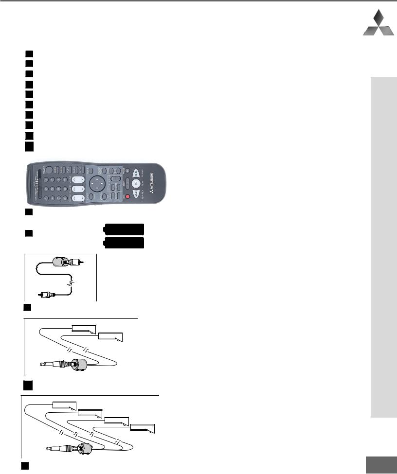
Please take a moment to review the following list of items to ensure that you have received everything included:
1Remote Control
2(2) AAA Batteries
3(1) Digital Audio Cable
4 |
(1) Double IR Emitter Cable |
5 |
(1) Quadruple IR Emitter Cable |
6 |
Product Registration Card |
7 |
Owner’s Guide |
8 |
Quick Reference Card |
9 |
NetCommand™ Guide |
10 Connection Con gur at ion Di agr ams
1 Remote Control
2 (2) AAA Batteries
3 (1) Digital Audio Cable
4 (1) Double IR Emitter Cable
5 (1) Quadruple IR Emitter Cable
Special Features
Your new High De ni tion bi gscr een t el evi si on has many special features that make it the per-
fect addition to your home entertainment system.
Below we have highlighted a handful.
Fully Integrated HDTV
Your Mitsubishi bigscreen TV can receive all |
|
|
approved terrestrial broadcast digital signals, |
|
|
non-scrambled digital cable signals, terrestrial |
|
|
analog signals and non-scrambled analog cable |
|
|
signals that use a standard offset carrier system. |
|
|
Further, your TV will display all High De ni tion |
Unpacking |
|
signals as 1080i True HDTV™ and all standard |
||
|
||
de ni tion si gnal swi ll be di spl ayed as 480p. |
|
|
NetCommand™Home Network Con- |
|
|
trol System |
|
|
NetCommand™ features and technology patent |
|
|
pending. |
Your |
|
Your Mitsubishi bigscreen HDTV offers a new |
||
level of networking to combine selected older |
||
products with new and future digital products. |
New |
|
|
||
NetCommand™ supports IEEE 1394 connec- |
|
|
tions, HAVi (Home Audio Video Interoperability) |
TV |
|
Control system, Audio Video Control system |
||
|
||
(AV/C), 5C copy protection and IR control of |
/ |
|
selected older products such as VCRs, DVD |
||
Special |
||
players, cable boxes or satellite receivers. All |
||
|
||
operating in a similar manner using on-screen |
|
|
graphical menus and a single remote control. |
|
|
See the NetCommand™ Guide for instructions |
|
|
on how to use this feature. |
Features |
|
Wide Screen Picture Format |
||
|
||
You will be able to view pictures as the directors |
|
|
intended you to see them. Both DTV and DVD’s |
|
|
supporting the widescreen format will enable you to |
|
|
enjoy a theater feel in the comfort of your home. |
|
|
PIP/POP Viewing Option |
|
|
Using Picture-in-Picture and Picture-outside-Pic- |
|
|
ture will give you exciting options for viewing |
|
|
your favorite programs. |
|
|
V-Chip Technology |
|
|
Your Mitsubishi bigscreen will allow you to |
|
|
restrict viewing of programming by general con- |
|
|
tent, category contents, or even by time. |
9 |
|
|

Installation |
|
Front Control Panel Functions |
.....12 |
Back Panel Functions .............. |
13-14 |
Installation Con gur at ions and |
|
NetCommand™ Setup ................ |
15 |
NetCommand™ Supported Devices 16 |
|
Connecting to Your New Mitsubishi |
|
Bigscreen: |
|
Antenna or Wall Outlet Cable for |
|
Digital Broadcasts ................... |
17 |
Analog Antenna, Wall |
|
Outlet Cable or Cable Box ...... |
18 |
Analog VCR ................................ |
19 |
A/V Receiver.............................. |
20 |
DVD Player or S-Video VCR or |
|
Satellite Receiver ..................... |
21 |
External DTV Receiver ........ |
22-23 |
Computer and the IR Home |
|
Theater Control and |
|
IR Repeater ................................ |
24 |
IMPORTANT NOTES ...................... |
25 |
NetCommand™ Setup ............. |
26-35 |
11
Part II: Installation
Front Control Panel
Front Control Panel Functions
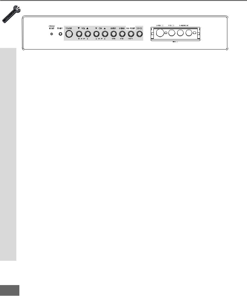
Figure 1. Front Control Panel.
The buttons on the front control panel that are highlighted in gray are duplicated on the remote control. The top row of labels show the control functions when there are no TV menus displayed on the screen. The bottom row of labels show the control functions when the TV menus are displayed on the screen. See Remote Control Functions: Overview, page 60, for details on their functions.
System Reset
If the TV will not respond to either the remote control or the front panel controls and will not power off, press the SYSTEM RESET button with a pointed item like the point of a ball point pen. The TV will turn off and the TIMER light will ash qui ckl yf or about one minute. When the TIMER light stops ashi ng, you ma y t ur n on t he TV agai n. The changes you made while the TV was on before you used the SYSTEM RESET button may be
cancelled, however, the changes you made previously are not cancelled. Only the changes since the last power on may be lost when the system reset button is pressed. All other settings are retained.
Timer
The green light is a multi-function indicator. Each time the TV is plugged into the wall electrical outlet, or when power is restored after a power failure, or after using the SYSTEM RESET button, this light will ash r api dl yf or about one mi nut e. Do not at temp t tot ur n
on the TV during this period, wait for the ashi ng t ost op bef or e at temp t ing t ot ur n t he TV on. When the TV is turned on, the light will be illuminated steadily. If the TV has been programmed to turn on automatically using the Timer feature, this light will ash sl owl y while the TV is powered off.
A/V Reset
Press this button to reset all A/V memories to the factory default settings.
Input 5
This input can be used for convenient connection of a camcorder or other video device to the TV. Please note that if you connect to the S-VIDEO terminal, the VIDEO terminal is deactivated. The VIDEO terminal is active when there is no S-Video connection.
12
Part II: Installation
 10
10
 Back Panel
11

1 |
2 |
12 |
|
9 |
|
3 |
|
8 |
4 |
|
5 |
|
6 |
7 |
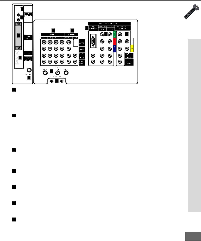
1 Inputs 1-4
These inputs can be used for the connection of a VCR, Super VHS (S-VHS) VCR, DVD player, standard satellite receiver, or other A/V device to the TV. Please note that if you connect to the S-VIDEO terminal, the VIDEO terminal is deactivated. The VIDEO terminal is active when there is no S-Video connection.
2 Output (Monitor and PIP)
The Monitor Output sends the TV audio and video signals from Ant-A, Ant-B and Inputs 1-5 to a VCR or other analog A/V equipment. It will also send digital audio and video signals from Ant-DTV and IEEE-1394 products that are not copy protected, and convert them to analog signals. From VGA, Component 1 and 2 and Input-DTV, no signals will be sent. The PIP output sends the PIP’s or POP’s audio signal to an ampli er or wirel ess headphones. If no PIP or POP is displayed, the PIP output will not send any audio.
3 Antenna (ANT-A, LOOP OUT, and ANT-B)
ANT-A and ANT-B receive analog NTSC signals from VHF/UHF antennas or an analog NTSC cable system. LOOP OUT sends the ANT-A signal out to another component, such as a cable box or VCR.
4 IR Emitter-Repeater
Connecting IR emitters here allows the TV to pass IR commands from most IR remote controls to other A/V devices that are out of range of the remote control.
5 VGA
This input can be used for the connection of a computer. Please see Appendix B, page 73, for signal compatibility.
6 Component Inputs 1-2
These inputs can be used for the connection of A/V equipment with component video outputs, such as a DVD player. Please see Appendix B, page 73, for signal compatibility.
7 DTV Input
Functions Panel Back
This input is used to connect a DTV receiver, and can be con gur ed f or HDTV s i gnal types |
|
component (YPrPb), RGB sync on green, and RGB plus H&V. Please see Appendix B, |
13 |
page 73, for signal compatibility. |
|
|
Part II: Installation
Back Panel Functions
 10
10
 Back Panel
11

1 |
2 |
12 |
|
9 |
|
3 |
|
8 |
4 |
|
5 |
|
6 |
7 |
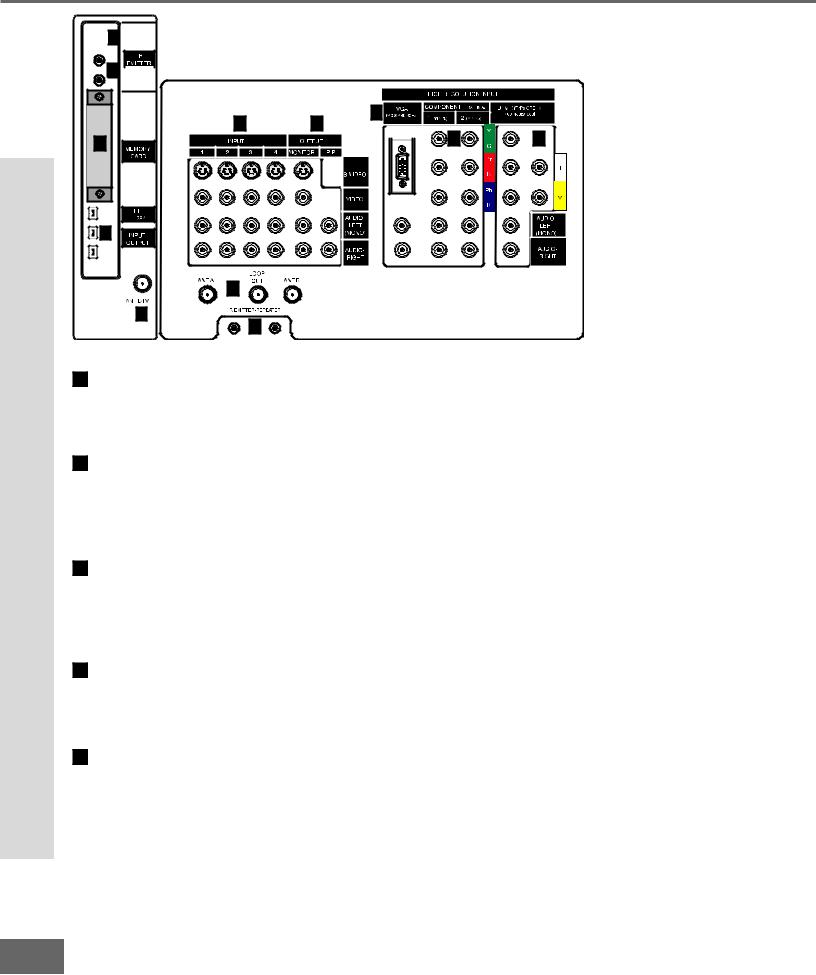
8 Antenna DTV (ANT-DTV)
This input receives digital TV signals from a VHF/UHF antenna or unscrambled digital cable system. If the TV receives scrambled signals on this input, it will not be able to decode them. In this case, your cable company must provide a decoding box.
9 IEEE-1394 Input/Output
These jacks allow the TV to connect to one or more external A/V products by means of a single cable. Three jacks are provided for this purpose, which allow for a high degree of exi bi lity for connect ing your syst emto get her . Please ref er to the Net Co mma nd ™ Guide for IEEE-1394 device connection details.
10 Digital Audio Output
This output provides digital audio streams, such as Dolby Digital or other types of digital audio, received in the signal from the ANT-DTV input or the IEEE-1394 devices. This output is intended to be connected to an external audio receiver that is capable of decoding the digital streams and converting them to analog signals suitable for driving loudspeakers.
1 IR Emitter-Home Theater Control Output
Two jacks are provided for connecting IR emitters. These emitters are used to control external analog devices such as VCRs, DVDs, cable boxes, satellite receivers and audio receivers by means of the NetCommand™ features of the TV.
12 Memory Card
The card slot behind the cover allows the software of the TV to be updated with expanded
features by use of a |
ash car d pr ovi ded by Mi |
tsubi shi . The TV does not |
come wi |
tha |
|
card and does not require a card when it is |
rst |
recei ved. You shoul dnot at temp t |
touse |
||
a ash car d t hat isnot |
aut hor ized by Mi tsubi shi |
or inser t any ot her itemi |
nt ot hi ssl ot as |
||
this may cause damage to your TV that is not covered by your warranty. When software updates are available, they will be announced on our web site, www.mitsubishi-tv.com. If you return your Owner’s Registration card with your model and serial number, you may receive written noti cat ion.
14
Part II: Installation
Installation Con gur at ions & Ne t Co mma nd™S e t up
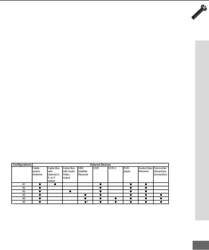
With this book you will nd f ol d- out pages t hat show 6 over vi ew d i agr ams of st andar d, pr e- established system connections, called con gur at ions. These di agr ams speci fy t he i nput s to use on the TV and on the NetCommand™ supported Audio Video (A/V) Receivers.
Later pages in this book will show details on how to connect devices to individual TV inputs.
Use the con gur at ion t hat mo st cl osel yma t ches t he devi ces you wi sh t oconnect tot he TV. Connect those devices as closely as possible to the diagram. It is OK if you cannot match the diagram perfectly. The NetCommand™ setup system will allow you to alter the con gur at ion t oma t ch changes you need t oma ke. If you do not have one of the devices speci ed i nt he con gur ati on, the Net Comma n d™se t up syst emwi l l give you the
option to select “None” for that device. As an example, if you do not have an A/V receiver, connect the left and right stereo audio cables from each device directly to the TV. In the NetCommand™ Setup system you will be given the opportunity to specify “None” for A/V receiver and the TV will know to use the TV speakers for all sound. You can use brands and/or models of devices that are not supported by NetCommand™ by selecting “Other”. On the nal scr een f or the set up t her e i san “ Edi t” opt ion. The edi t opt ion wi ll al low y ou t o change the settings; for instance you can select a different TV input or A/V receiver input to use with a device, add a device that is not in the original con gur at ion, or gi ve a di ffer ent name to the device. The setup can also be edited at a later date, from Setup in the TV menu, to adjust to changes in your system.
For instructions concerning the connection and addition of IEEE 1394 devices to your system, see the separate NetCommand™ Guide. The devices for each con gur at ion ar e shown in the table below.
NetCommand™ Setup Con gur at ions
Table 1.
*High De ni tion DBS Re cei ver .
up t e nd™S mma Co t Ne & ions at gur Con Installation
15
Part II: Installation
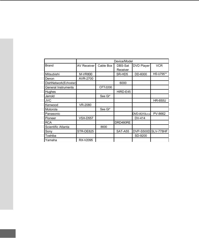
NetCommand™ Supported Devices
NetCommand™ Supported Devices
Following is a list of devices by several manufacturers that have been tested and shown to be compatible with the NetCommand™ control system. When you use these devices you will be able to control them without changing the setting of the remote control from TV to another product.
NetCommand™ Compatible Legacy Devices
*No special models
**Supports both VCR-A and VCR-B remote control system
Since similar devices from the same manufacturer often operate the same way, other models may be compatible, however they have not been tested so not all NetCommand™ functions may be available. For devices that are not supported by NetCommand™, you will need to use that device’s original remote control or program the TV remote to operate these devices in the traditional manner.
16
Part II: Installation
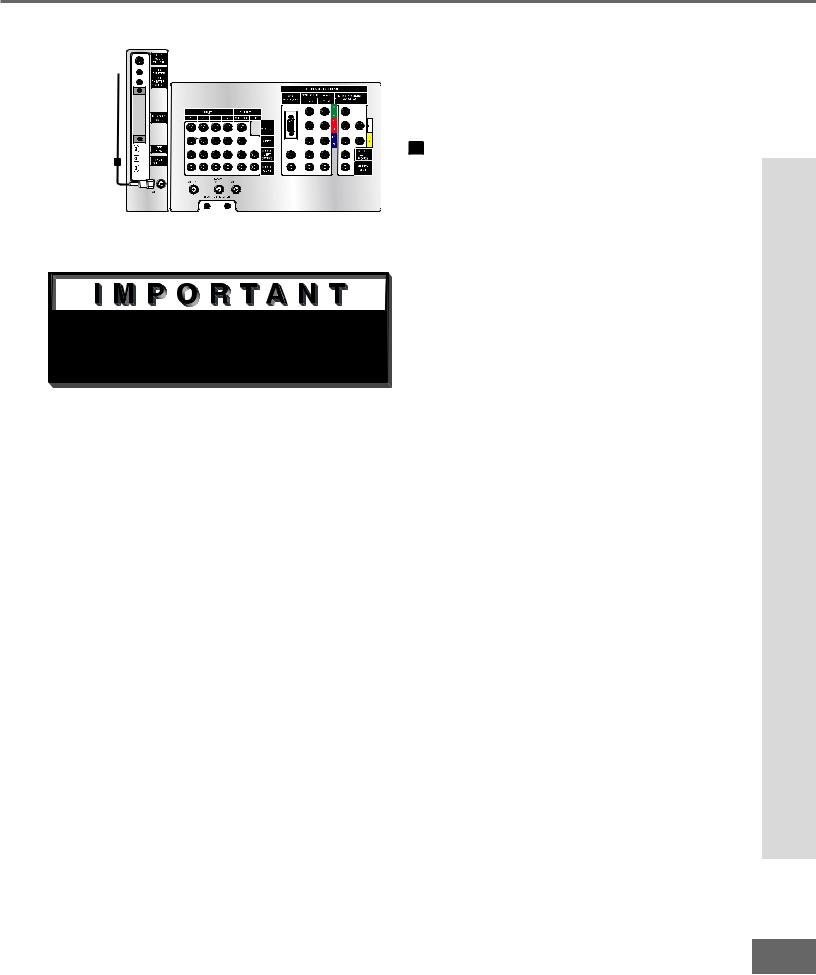
Connecting Antenna or Wall Outlet Cable for Digital Broadcasts
Antenna or Wall Outlet Cable
for digital broadcasts
TV back panel
1
Figure 1. Antenna or wall outlet cable.

 Additional connection cables are not provided with the TV. They should be available at most electronic stores.
Antenna or Wall Outlet Cable for Digital Broadcasts.
For cable or antenna with coaxial lead (Figure 1)
1Connect the incoming cable to ANT-DTV on the TV back panel.
Mitsubishi strongly recommends against using antennas with twin at leads. Twi n at lead ant enna wir es are subj ect to interference which may adversely affect the performance of the TV. We recommend using coaxial antenna cable.
Broadcasts Digital for Cable Outlet Wall or Antenna Connecting
17
Part II: Installation
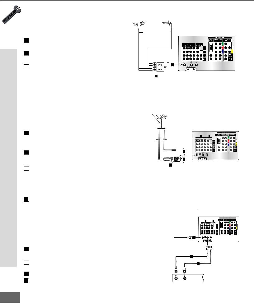
Connecting an Analog Antenna, Cable, or Cable Box
Connecting an Analog Antenna, Wall Outlet Cable, or Cable
Box |
VHF Antenna |
UHF Antenna |
(Channels 2-13) |
(Channels 14-69) |
Separate UHF and VHF Antennas
(Figure 1)
1Connect the UHF and VHF antenna leads to the UHF/VHF combiner.
2Push the combiner onto ANT-A on the
TV back panel.

 UHF/VHF combiners are not provided with the TV. They should be available at most electronic stores.
Mitsubishi strongly recommends against using antennas with twin at leads. Twi n at lead ant enna wir es are subj ect to interference which may adversely affect the performance of the TV. We recommend using coaxial antenna cable.
Flat Twin Lead
Flat Twin Lead
TV back panel
External
Antenna or Cable
300 Ohm to
75 Ohm
Combiner
UHF
2
VHF
 Back Side
1
Figure 1. Connecting separate UHF and VHF antennas.
Antenna or Wall Outlet Cable for Analog Broadcasts.
(Figure 2)
For antennas with twin at lead
1For antenna with twin at leads, connect the 300-Ohm twin leads to the transformer.
2Push the 75-Ohm side of the transformer onto ANT-A on the TV back panel.

 300-Ohm to 75-Ohm matching transformers are not provided with the TV. They should be available at most electronic stores.
For cable or antenna with coaxial lead
 3
3 Connect the incoming cable to ANT-A on the TV back panel.
Mitsubishi strongly recommends against using antennas with twin at leads. Twi n at lead ant enna wir es are subj ect to interference which may adversely affect the performance of the TV. We recommend using coaxial antenna cable.
Cable Box
(Figure 3)
1 Connect the incoming cable to ANT-A on the TV back panel.

 Connect two coaxial cables as follows:
One from LOOP-OUT on the TV back panel to 2 IN on the cable box back panel.
 3
3 One from OUT on the cable box back panel to ANT-B on the TV back panel.
TV back panel
300 Ohm Flat
Twin Lead
1 2
75 Ohm
Coaxial Cable

 3
3
2 |
1
Optional 300 Ohm to 75 Ohm
Matching Transformer
Figure 2. Connecting antenna or wall outlet cable for analog broadcasts.
|
|
TV back panel |
|
|
|
|
1 |
5 |
|
|
|
2 |
|
|
|
|
|
6 |
7 |
Incoming |
|
|
|
|
Cable |
1 |
3 |
|
|
|
|
|
|
|
|
|
4 |
|
|
2
3
Cable Box
back panel section
IN |
OUT |
Figure 3. Connecting the cable box.
18
Part II: Installation
Connecting an Analog VCR
TV back panel
Incoming Cable
1
|
|
2 |
3 |
|
VCR back panel |
|
|
|
|
2 |
|
AUDIO OUT |
AUDIO IN |
VIDEO OUT |
IN |
|
L |
L |
(Y/C) |
|
|
|||
Antenna |
1 |
2 |
|
1 |
|
MONITOR |
|||
|
|
R |
R |
|
3 |
|
|
|
|
OUT |
|
|
|
|
Figure 1. Connecting VCR with antennas or wall outlet cable.

 Additional connection cables are not provided with the TV. They should be available at most electronic stores.
TV back panel
Incoming Cable
1
2
 4
4
Cable Box Rear Terminals
2


OUT |
IN |
3 |
VCR back panel
3 |
AUDIO OUT |
AUDIO IN |
VIDEO OUT |
IN |
L |
L |
(Y/C) |
|
|||
Antenna |
1 |
2 |
1 |
MONITOR |
|||
|
R |
R |
|
|
4 |
|
|
OUT
Figure 2. Connecting VCR with cable box.
|
|
TV back panel |
|
|
|
|
|
1 |
|
White |
|
|
|
|
|
2 |
Red |
|
|
|
|
|
|
Attach |
|
|
|
|
|
||
|
|
|
|
|
|
|
|
only |
|
|
|
|
|
|
|
one |
|
|
|
|
|
|
|
cable |
|
|
|
|
|
|
|
type |
|
|
|
|
|
|
|
1 |
|
|
|
|
|
|
|
|
|
|
|
|
|
|
1 |
|
|
|
|
|
|
|
Attach |
|
|
|
|
|
|
|
only |
|
|
|
|
AUDIO OUT |
AUDIO IN |
VIDEO OUT |
one |
|
|
IN |
White |
|
|
|
cable |
|
|
L |
L |
(Y/C) |
type |
||
|
|
2 |
|
|
|
1 |
1 |
|
|
Antenna |
|
1 |
2 |
|
|
|
|
|
MONITOR |
|
|||
VCR back panel |
|
Red |
R |
R |
|
|
|
|
|
|
|
||||
If your VCR has a video
channel or RF ON/OFF OUT switch, set to OFF.
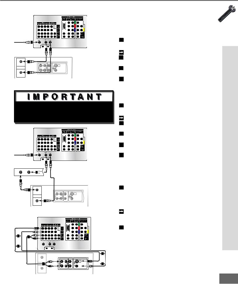
Analog Antennas or Wall Outlet Cable
(Figure 1)
1 Connect the incoming cable to ANT-A on the TV back panel.
Connect two coaxial cables as follows:
2One from LOOP-OUT on the TV back panel to ANTENNA IN on the VCR back panel.
3One from VCR back panel ANTENNA OUT to ANT-B on the TV back panel.
4 Now complete gur e 3, steps 1- 2.
Cable Box
(Figure 2)
1 Connect the incoming cable to ANT-A on the TV back panel.
Connect three coaxial cables as follows:
2One from LOOP-OUT on the TV back panel to IN on the back of the cable box.
3One from OUT on the back of the cable box to ANTENNA IN on the VCR back panel.
4One from ANTENNA OUT on the VCR back panel to ANT-B on the TV back panel.
5 Now complete gur e 3, steps 1- 2.
Adding Composite Video or S-Video with Audio Connections
(Figure 3)
1Connect a video cable from VIDEO OUT on the VCR back panel to VIDEO INPUTS 1, 2, 3, or 4 on the TV back
panel.
If you have a S-VHS VCR, follow the same steps using the S-Video terminals on the VCR and TV (in place of the composite terminals).
2Connect a set of audio cables from AUDIO OUT on the VCR back panel to AUDIO INPUT 1, 2, 3, or 4 on the TV back panel. The red cable connects to the R (right) channel and the white cable connects to the L (left) channel. If your VCR is mono (non-stereo), connect only the white (left) cable.
VCR Analog an Connecting
Figure 3. Connecting the VCR Audio/Video. |
19 |
|
Part II: Installation
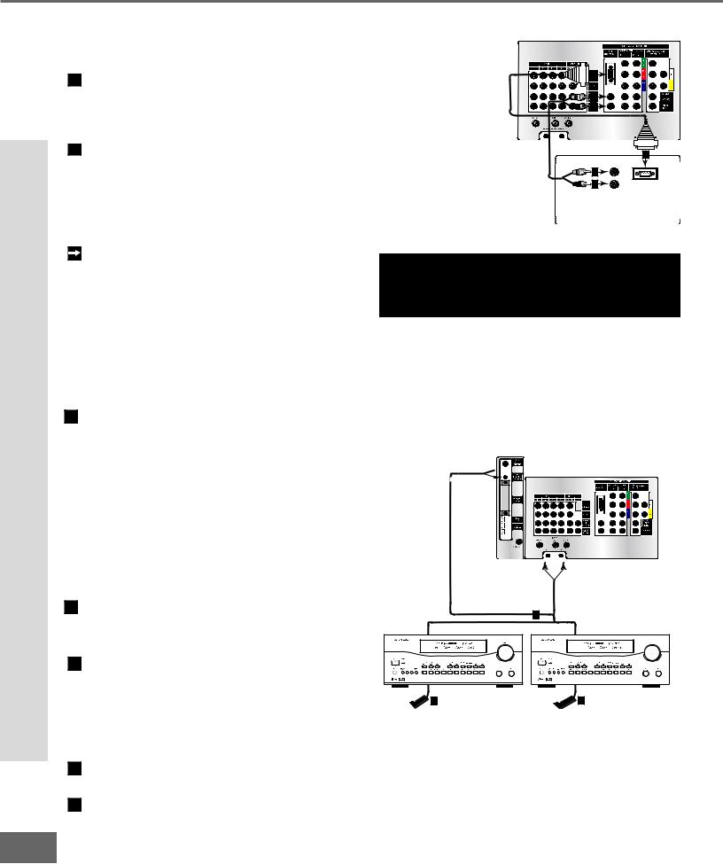
Connecting an Audio/Video Surround Sound Receiver
Connecting an Audio/Video Surround Sound Receiver
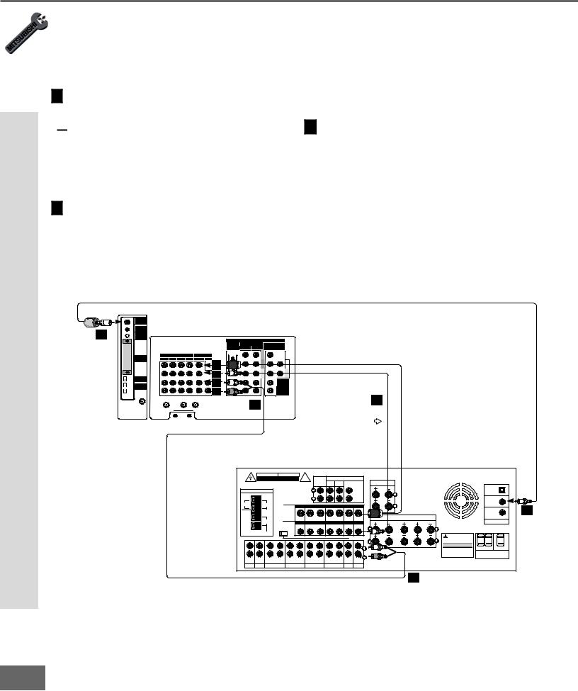
Connecting an A/V Receiver
(Figure 1)
1Connect a video cable from Monitor VIDEO OUTPUT on the back of the TV to the TV VIDEO INPUT on the back of the A/V Receiver.
 If you have connected a S-VHS VCR to the A/V Receiver, then follow the same video connection using the S-Video cable and terminals on the TV and A/V Receiver (in place of the VIDEO cable).
2Connect a set of audio cables from the Monitor AUDIO OUTPUT on the back of the TV to the TV AUDIO INPUT on the back of the A/V Receiver. The red cable connects to the R (right) channel and the white cable connects to the L (left) channel.
DIGITAL
AUDIO
OUTPUT
IR |
TV Rear Panel |
EMITTER |
|
3 THEATERHOME
CONTROL |
|
|
|
|
|
|
|
|
|
|
|
Ferrite end |
|
|
|
|
|
|
HIGH RESOLUTION INPUT |
|
|||
|
|
|
|
|
VGA |
COMPONENT |
|
480i/480p |
DTV |
(YPrPb/GRBHV) |
|
|
|
|
|
|
640 X 480,60Hz |
1 (YPrPb) |
2 |
(YPrPb) |
|
480i/480p/1080i |
|
|
|
|
|
|
OUT |
|
|
|
|
Y |
|
|
|
|
INPUT |
|
|
|
|
|
|
|
|
|
|
|
|
PUT |
|
|
|
|
G |
|
|
MEMORY |
1 |
2 |
3 |
4 |
MONI |
PI |
|
|
|
|
|
CARD |
TOR |
P |
|
|
|
P |
|
||||
|
|
|
|
|
|
|
|
|
|
r |
H |
|
|
|
|
|
|
|
|
|
|
R |
|
|
|
|
|
|
|
S-VIDEO |
|
|
|
|
|
|
|
|
|
|
|
|
|
|
|
P |
|
|
|
|
|
|
|
VIDEO |
|
|
|
b |
V |
|
|
|
|
|
|
|
|
|
B |
||
IEEE |
|
|
|
|
|
|
|
|
|
|
|
|
|
|
|
|
|
|
|
|
|
|
|
-1394 |
|
|
|
|
|
AUDIO- |
|
|
|
|
AUDIO- |
|
|
|
|
|
|
LEFT |
|
|
|
|
LEFT |
INPUT/ |
|
|
|
|
|
(MONO) |
|
|
|
|
(MONO) |
OUTPUT |
|
|
|
|
|
|
|
|
|
|
|
|
|
|
|
|
|
AUDIO- |
|
|
|
|
AUDIO- |
|
|
|
|
|
|
RIGHT |
|
|
|
|
RIGHT |
|
|
|
LOOP |
|
|
|
|
|
|
|
|
|
ANT-A |
|
OUT |
|
ANT-B |
|
|
|
|
|
|
ANT-DTV |
2 |
|
IR EMITTER-REPEATER |
If connecting a digital A/V Receiver with Dolby DigitalTM surround sound.
3Connect one end of the digital audio cable supplied with the TV to the DIGITAL AUDIO OUTPUT on the back of the TV (connect
the end of the cable with the ferrite or plastic cylinder). Connect the other end to the COAXIAL DIGITAL INPUT on the back
of the A/V Receiver. Check the Owner’s Guide for the A/V Receiver for information concerning the use of the digital input and switching between the digital sound and analog stereo sound from the TV.
Use only if connecting a Dolby Digital A/V Receiver
1
Attach only one cable type
|
A/V Receiver Rear Panel |
|
|
|
|
|
|
|
|
|
|||||||
|
WARNING |
|
AVIS |
|
! |
|
|
|
|
|
|
|
|
|
|
|
|
|
RISK OF ELECTRIC SHOCK |
|
RISQUE DE CHOC ELECTRONQUE |
|
REC |
|
|
PRE OUT |
|
|
|
|
|
|
|
||
|
DO NOT OPEN |
|
NE PAS ENLEVER |
|
|
|
|
|
|
|
|
|
|
|
|||
|
|
|
|
|
|
|
SOURCE |
SUR. |
FRONT |
|
|
SURROUND |
THIS DEVICE COMPLIES WITH PART 15 OF THE |
|
|
||
|
|
|
|
|
|
|
LINE OUT |
|
|
SPEAKERS (6Ω MIN.) |
|
|
|||||
|
|
|
|
|
|
|
|
|
|
|
|
FCC RULES. OPERATION IS SUBJECT TO THE |
|
|
|||
|
|
|
|
|
|
|
|
|
|
|
|
|
|
FOLLOWING TWO CONDITIONS: (1) THIS DEVICE |
INPUT-1 |
|
|
|
ANTENNA |
|
|
|
|
|
L |
|
|
|
|
CENTER |
|
MAY NOT CAUSE HARMFUL INTERFERENCE AND |
|
||
|
|
|
|
|
|
|
|
|
|
|
(2) THIS DEVICE MUST ACCEPT ANY INTERFERENCE |
(OPTICAL) |
|
||||
|
|
|
|
|
|
|
|
|
|
|
|
|
|
||||
|
|
|
|
|
|
|
|
|
|
|
|
|
|
L RECEIVED, INCLUDING INTERFERENCE THAT MAY |
|
|
|
|
|
|
|
|
|
|
R |
|
|
|
|
SUB |
|
CAUSE UNDESIRED OPERATION. |
|
|
|
|
|
|
|
|
|
|
|
|
|
|
WOOFER |
|
|
|
INPUT-2 |
|
|
|
|
|
|
|
|
|
|
|
|
|
|
|
|
|
|
||
AM |
75Ω |
|
|
|
|
|
|
|
|
|
|
|
|
|
|
(COAXIAL) |
|
|
S-VIDEO |
MONITOR |
VCR 1 |
VCR 2 |
TV |
|
DVD |
R |
|
|
|
||||||
|
|
|
|
|
|
3 |
|||||||||||
GND |
|
|
|
|
|
|
|
|
|
|
|
|
|
|
|
INPUT-3 |
|
|
|
|
|
|
|
|
|
|
|
|
|
|
FRONT |
CENTER |
FRONT |
(COAXIAL) |
|
|
|
|
|
OUT |
|
OUT |
IN |
OUT |
|
IN |
IN |
IN |
|
|
|||
|
300Ω |
|
|
|
|
SPEAKERS-A (6Ω MIN.) |
(6Ω MIN.) |
SPEAKERS-B (6Ω MIN. ) |
DIGITAL AUDIO |
|
|||||||
|
|
VIDEO |
MONITOR |
VCR 1 |
VCR 2 |
TV |
|
DVD |
|
|
|
|
|||||
|
|
|
|
|
|
|
|
|
|||||||||
|
|
|
ATUO |
OUT |
|
OUT |
IN |
OUT |
|
IN |
IN |
IN |
L |
|
|
|
|
|
|
|
STANDBY |
|
|
|
|
|
|
|
|
|
|
L |
|
|
|
|
FM |
ON |
OFF |
|
|
|
|
|
|
|
|
|
|
|
|
|
|
AUDIO |
|
|
|
|
|
|
|
|
|
σ |
|
|
|
|
MITSUBISHI |
|
|
|
|
|
|
|
|
|
|
|
τ |
|
|
|
R |
AUDIO/VIDEO RECEIVER |
|
||
|
|
|
|
|
|
|
|
|
|
|
|
|
R |
|
|
MODEL M-VR1000 |
|
|
|
|
|
|
|
|
|
|
|
|
|
|
|
POWER SUPPLY |
120V-60Hz |
|
|
|
|
|
|
|
|
|
|
|
|
|
|
L |
|
POWER CONSUMPTION |
552W, 732VA |
SWITCHED |
UNSWITCHED |
|
|
|
|
|
|
|
|
|
|
|
|
|
|
|
|||
|
|
|
|
|
|
|
|
|
|
|
|
|
|
DISTRIBUTED BY |
|
|
|
|
|
|
|
|
|
|
|
|
|
|
|
|
|
MITSUBISHI CONSUMER ELECTRONICS AMERICA |
AC 120V - 60Hz |
||
|
|
|
|
|
|
|
|
|
|
|
|
|
UNDER LICENSE FROM DOLBY LABORATORIES LICENSING |
INC. |
|
||
|
|
|
|
|
|
|
|
|
|
|
|
|
|
|
TOTAL 100W, 0.9A MAX |
||
|
|
|
|
|
|
|
|
|
|
|
|
|
"DOLBY", "PRO LOGIC" AND THE DOUBLE-D SYMBOL ARE |
6100 ATLANTIC BLVD |
MADE IN |
AC OUTLETS |
|
|
|
|
|
|
|
|
|
|
|
|
|
R |
OF DOLBY LABORATORIES CORPORATION. |
JAPAN |
|
||
IN |
IN |
OUT |
IN |
OUT |
IN |
OUT |
IN |
OUT |
IN |
IN |
IN |
1992 DOLBY LABORATORIES, INC. ALL RIGHTS |
NORCROSS, GA 30071-1305 |
FABRIQUE EN |
|
|
|
RESERVED |
JAPAN |
|
|
|
|||||||||||||
AUX |
CD |
TAPE 1 |
TAPE 2 |
VCR 1 |
|
VCR 2 |
|
TV |
DVD |
|
|
|
|
|
|
||
2
Figure 1. Connecting an Audio/Video Receiver
20
Part II: Installation
WARNING: Do not display the same stationary images on the screen for more that 15% of your total TV viewing in one week. Examples of stationary images are
letterbox top/bottom bars from DVD or other video sources, side bars when showing standard TV pictures on widescreen TV’s, stock market reports, video game patterns, station logos, web sites, or stationary computer images. Such patterns can unevenly age the picture tubes causing permanent damage to the TV. Please see page 70 for a detailed explanation.
Connecting a DVD Player
TV back panel
|
1 |
|
2 |
|
3 |
White |
5 |
Red |
4 |
|
DVD back panel
1 |
|
|
|
AUDIO OUT |
|
|
AC IN |
|
Y |
VIDEO |
|
5.1 CH SURROUND |
2CH |
BITSTREAM/PCM |
MITSUBISHI |
||
|
|
|
|
|
|
DVD PLAYER |
|
|
2 |
|
|
White |
CENTER |
|
|
MODEL DD-5000 |
|
CB |
|
5 |
|
L |
POWER SUPPLY |
120V~ 60Hz |
||
|
S |
|
|
POWER CONSUMPTION |
20W |
|||
3 |
|
|
4 |
|
|
|
|
|
CR |
|
Red |
|
R |
DISTRIBUTED BY |
|
||
|
|
|
|
MITSUBISHI DIGITAL ELECTRONICS |
||||
|
|
|
|
|
AMERICA, INC. |
|
||
|
VIDEO OUT |
SUBWOOFER SURROUND FRONT |
|
COAXIAL OPTICAL |
9351 JERONIMO ROAD |
|
||
|
|
|
IRVINE, CA 92618 |
|
||||
MADE IN JAPAN
Figure 1. Connecting the DVD player.

 See Appendix B, page 73, for component video signal compatibility information.

 For digital audio connections, see your DVD and A/V receiver Owner’s Guides.
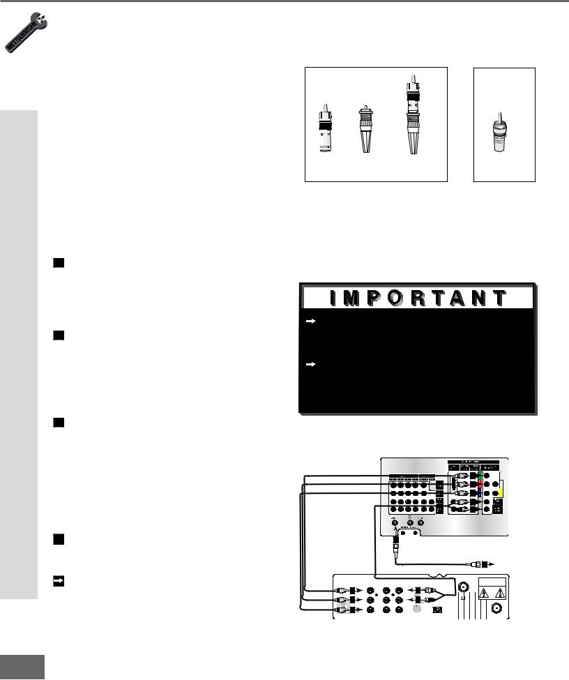
DVD Player with Component Video
(Figure 1)

 Connect the Component Video cables from Y/Cr/Cb or Y/Pr/Pb VIDEO OUT on the back of the DVD player to COM- PONENT-1 or COMPONENT-2 on the TV back panel, matching the correct connection:
1Y to Y
2Cr or Pr to Pr
3Cb or Pb to Pb

 Connect a set of audio cables from AUDIO OUT on the back of the DVD player to COMPONENT AUDIO Input 1 or 2 on the TV back panel. The red cable 4 connects to the R (right) channel, and the white cable 5 connects to the L (left) channel.
Connecting an S-Video VCR or Satellite Receiver
TV back panel
S-Video VCR or Satellite Receiver
(Figure 2)
1Connect an S-Video cable from VIDEO OUT on the device back panel to VIDEO INPUT-1, INPUT-2, INPUT-3, or INPUT-4 on the TV back panel.
|
1 |
|
|
|
2 |
Connect a set of audio cables from |
|
White |
|
|
|
||
2 |
Red |
|
|
|
|
AUDIO OUT on the device back panel to |
|
|
|
|
|
|
AUDIO INPUT-1, INPUT-2, INPUT-3, or |
|
Any S-Video Device |
|
|
|
|
INPUT-4 on the TV back panel. The |
|
|
|
|
|
red cable connects to the R (right) chan- |
|
|
|
AUDIO OUT |
AUDIO IN |
VIDEO OUT |
|
|
|
White |
L |
L |
(Y/C) |
1 |
nel and the white cable connects to |
|
2 |
1 |
2 |
|
|
|
|
Red |
R |
R |
|
|
the L (left) channel. If your device |
|
|
|
|
|||
|
|
|
|
|
|
|
|
|
|
|
|
|
is mono (non-stereo), connect only the |
Figure 2. Connecting an S-Video Device. |
|
white (left) cable. |
||||
|
|
|||||
Satellite or VCR Video-S or Player DVD a Connecting
21
Part II: Installation
Connecting an External DTV Receiver
Connecting an External DTV Receiver
DTV Connectors and Adaptors
(Figure 1)
The TV back panel has 5 RCA-type connectors, for the Input-DTV. The back panel of your external DTV receiver may use RCAtype connectors or BNC-type connectors. If your DTV receiver comes with BNC type connections, you will need to purchase BNC to RCA adaptors to connect the TV to the DTV receiver. These adaptors should be available at most electronic supply stores.
|
|
|
or |
BNC to |
|
Adaptor |
RCA |
RCA |
BNC |
Fitted to |
Connector |
Adaptor |
Connector |
Connection |
|
Figure 1. DTV connectors and adaptors.
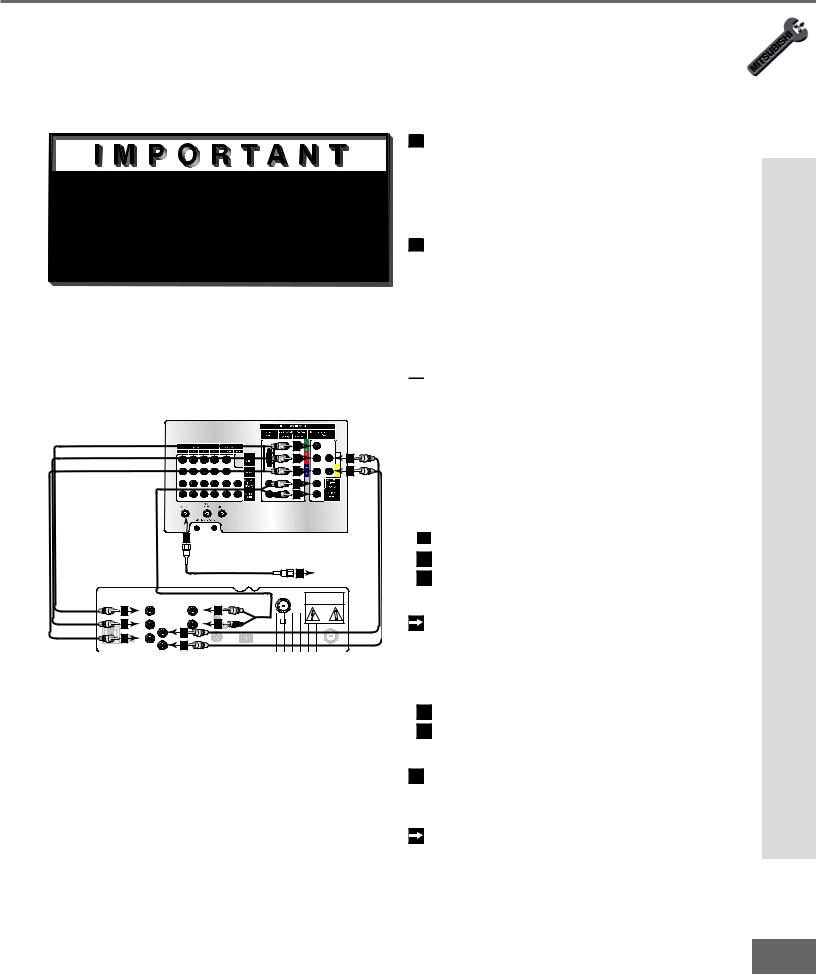
External DTV Receiver with Component Video Connections
(Figure 2)
1Connect the outside antenna, cable, or satellite to ANT, or SATELLITE IN on the
|
DTV receiver (see your DTV receiver’s |
|
|
|
|
|
|
|
|
|
|
owner’s guide for instructions, and cable |
See Appendix B, page 73, for compo- |
||||||||
|
compatibility). |
|||||||||
2 |
Connect the incoming terrestrial antenna, |
nent video signal compatibility informa- |
||||||||
|
or cable (not satellite) to ANT-A on the |
tion. |
|
|
|
|
|
|
|
|
|
For digital audio connections, see your |
|||||||||
|
TV back panel (a coaxial splitter, avail- |
|||||||||
|
able at most electronic supply stores, |
DTV receiver and A/V receiver Owner’s |
||||||||
|
may be required to complete this instal- |
Guides. |
|
|
|
|
|
|
|
|
|
lation). |
|
|
|
|
|
|
|
|
|
3 |
Connect the RCA-type cables from |
|
|
|
|
|
|
|
|
|
|
the YPrPb outputs on the DTV receiver |
|
|
|
|
|
|
|
|
|
|
to Input-DTV on the TV back panel. |
|
|
TV back panel |
|
|
|
|
||
|
You may need to set the Input-DTV |
|
|
|
|
|
|
|
3 |
|
|
assignment to YPrPb using the “Change” |
|
|
|
|
|
|
|
|
|
|
|
|
|
|
|
|
|
3 |
|
|
|
option of the Edit Setup menu. Select |
|
|
|
|
|
|
|
3 |
|
|
|
|
|
|
|
|
|
|
|
|
|
this device to change and this assign- |
|
|
White |
|
|
|
|
4 |
|
|
|
|
Red |
|
|
|
|
4 |
|
|
|
|
|
|
|
|
|
|
|
|
|
|
ment will be available. |
|
|
|
|
|
|
|
|
|
4 Connect the L (left) and R (right) audio |
|
|
|
2 |
|
|
|
|
|
|
|
cables from the DTV receiver to Input- |
|
|
|
|
|
|
|
|
Incoming Antenna, |
|
DTV AUDIO on the TV back panel. |
|
|
|
|
|
|
|
2 |
|
|
|
|
|
|
|
|
|
or Cable. |
||
|
To utilize the bene ts of a dig tal A/V |
|
|
|
|
|
|
|
|
CAUTION |
|
|
|
|
|
|
|
|
|
RISK OF ELECTRICAL SHOCK |
|
|
|
3 |
|
AUDIO |
AUDIO |
|
4 |
|
|
DO NOT OPEN |
|
|
|
|
|
|
|
|
|
||
|
receiver, connect your DTV receiver’s |
|
Y |
L |
|
L |
VCR |
|
|
|
|
|
|
CONTROL |
|
|
|
||||
|
3 |
|
|
|
|
|
|
|
||
|
Pr |
|
|
|
4 |
DIGITAL |
CH 3 |
|
||
|
|
|
R |
|
|
|
|
CH 4 |
|
|
|
digital audio out to a digital input on your |
RF |
|
|
|
|
|
AUDIO OUT |
|
|
|
|
VIDEO |
VIDEO |
|
S-VIDEO |
|
|
TELLITE IN |
||
|
PHONE JACK REMOTE |
|
|
|
|
|||||
|
|
3 |
Pb |
|
|
|
|
|
|
|
|
|
|
|
|
|
|
|
|
|
|
|
digital A/V receiver. |
Figure 2. Connecting the DTV receiver with component |
||||||||
|
|
video connections. |
|
|
|
|
|
|
|
|
22
Part II: Installation
Connecting an External DTV Receiver
External DTV Receiver with RGB Video Connections
(Figure 1)

 See Appendix B, page 73, for RGB video signal compatibility information.

 For digital audio connections, see your DTV receiver and A/V receiver Owner’s Guides.
|
|
|
TV back panel |
|
|
|
|
|
|
|
|
|
|
|
|
3 |
|
|
|
|
|
|
|
|
4 |
6 |
|
|
|
|
|
|
|
5 |
7 |
|
|
|
White |
|
|
|
8 |
|
|
|
|
Red |
|
|
|
8 |
|
|
|
|
|
|
|
|
|
|
|
|
|
2 |
|
|
|
|
|
|
|
|
|
|
|
|
2 |
Incoming Antenna, |
|
|
|
|
|
|
|
or Cable. |
|
|
|
|
|
|
|
|
|
CAUTION |
|
|
|
|
|
|
|
|
RISK OF ELECTRICAL SHOCK |
|
3 |
|
AUDIO |
|
8 |
|
|
DO NOT OPEN |
|
|
|
|
|
|
|
||
|
|
G |
|
L |
VCR |
|
|
|
|
|
|
CONTROL |
|
|
|
||
|
|
|
|
|
|
|
|
|
|
4 |
R |
|
|
8 |
|
CH 3 |
|
|
|
|
DIGITAL |
CH 4 |
|
|||
|
|
6 |
|
|
|
|||
|
RF |
H |
|
|
AUDIO OUT |
|
|
|
|
|
|
|
|
|
|||
|
5 |
B |
7 |
|
|
|
|
|
PHONE JACK |
REMOTE |
V |
|
S-VIDEO |
|
|
TELLITE IN |
|
Figure 1. Connecting the DTV receiver with RGB video connections.
1Connect the outside antenna, cable, or satellite to ANT, or SATELLITE IN on the DTV receiver (see your DTV receiver’s owner’s guide for instructions, and cable compatibility).
2Connect the incoming terrestrial antenna,
or cable (not satellite) to ANT-A on the TV back panel (a coaxial splitter, available at most electronic supply stores, may be required to complete this installation).

 Connect the RGB cables for the DTV receiver to the Input-DTV on the TV back panel. You may need to set the Input-DTV assignment to RGB using the “Change” option of the Edit Setup menu. Select this device to change and this assignment will be available.
|
3 |
|
DTV Receiver |
|
TV Back Panel |
|
|
G (green) |
= |
Y/G |
|
|
|
|
|||
4 |
|
R (red) |
= |
Pr/R |
|
5 |
|
B (blue) |
= |
Pb/B |
|
If the DTV receiver has outputs for H and V sync, connect as listed below
(DO NOT connect if DTV receiver uses “Sync on Green”):
6 |
H (horizontal sync) = |
H |
7 |
V (vertical sync) = |
V |
8Connect the L (left) and R (right) audio cables from the DTV receiver to Input-
DTV AUDIO on the TV back panel. To utilize the bene ts of a dig tal A/V receiver, connect your DTV receiver’s
digital audio out to a digital input on your digital A/V receiver.
Receiver DTV External an Connecting
23
Part II: Installation
Connecting a Computer and the IR Home Theater Control and Repeater
24
Connecting a Computer with a VGA Monitor Output
Connecting a Computer |
|
TV back panel |
|
|
|
|
|
|
|
|
|
||
(Figure 1) |
|
|
MONITORVGA CABLE |
|
|
|
1 |
Connect VGA Monitor Out from the com- |
|
|
|
|
|
|
|
|
|
1 |
|
|
|
puter to VGA on the TV back panel using a |
White |
2 |
|
|
|
|
VGA compatible monitor cable. See Appen- |
Red |
2 |
|
|
|
|
|
|
|
|||
|
|
|
|
|
||
|
dix B, page 73, for VGA signal compatibility. |
|
|
|
CABLE |
|
2 |
|
|
|
|
|
|
Connect the L (left) and R (right) audio |
|
|
|
|
VGAMONITOR |
|
|
|
Computer with VGA Monitor Output. |
1 |
|||
|
cables from the computer to VGA AUDIO |
|
|
2 |
L |
|
|
|
|
|
|
AUDIO |
|
|
on the TV back panel. In cases where your |
|
2 |
R |
VGA OUTPUT |
|
|
computer’s audio output is a single mini- |
|
|
|
|
|
|
jack, a splitter is needed to complete this |
|
|
|
|
|
|
connection. |
Figure 1. |
Connecting a computer with a VGA monitor output. |
|||
|
To utilize the bene ts of a dig tal A/V |
CAUTION: To assure continued FCC compliance, |
||||
|
receiver, connect your computer’s digital |
|||||
|
the user must use a shielded video interface cable |
|||||
|
audio out, if available, to a digital input on |
|||||
|
with bounded ferrite cores, when using the VGA |
|||||
|
your digital A/V receiver. |
|||||
|
input. |
|
|
|
|
|
Connecting the IR-Home Theater Control and IR Repeater
(Figure 2)
IR Emitter-Home Theater Control
These emitters are not IR repeaters, but instead used by the NetCommand feature to control supported devices.
1 a: Connect the IR emitter to IR EMITTERHOME THEATER CONTROL on the TV back panel.
OR
IR Emitter-Repeater
These emitters are not used by NetCommand, but will repeat any IR command received by the TV. These emitters allow the TV to be the remote control sensor for other devices that are outside of the range of the handheld remote control. Do not use these repeaters with devices that can receive the remote control signal directly, as the signals can interfere with each other.
1 b: Connect the IR emitter to IR EMITTER-
REPEATER on the TV back panel.
THEN
2Place the IR emitter cable under or along the side of the A/V device. Place the IR lens directly in front of the A/V device’s infrared signal receiver. Infrared signal receivers are usually behind the front trans-
lucent panel of the device.
3Place unused transmitters in an out-of-the- way location.
4For permanent installation of the IR emitter cable, use the included adhesive tape to secure the bottom of the emitter to the anchoring object of your choice.


 TV back panel
AND/OR
1
Other A/V Device |
A/V Receiver |
2 |
2 |
Figure 2. Connecting the IR Home Theater Control and/or Repeater.

Part II: Installation
Warning: Do not leave stationary, toolbar, or partial images on-screen for extended periods of time. Mix the types of pictures shown. Uneven picture tube aging is NOT covered by your warranty.
The VGA capability of this television is designed for occasional use ONLY.
It is not meant to be used as a work station or to view static or odd-shaped images for an extended period of time. Any device connected to your television via the VGA port, including, but not limited to, personal computer, game system, or digital set-top box, must have its screen saver function activated to prevent damage to the television. We DO NOT recommend the use of any external device that does not have a screen saver function with this television.
We recommend that screen saver activation time be set to less than ve minutes when using a device through the VGA port. You should also use lower brightness and contrast settings. If your computer programs allow, toolbars should be set to hidden mode.
Please remember that most computer programs and video game systems display static images, such as boxes, buttons, tool bars, and game scores that can damage the television if used for extended periods of time, repeatedly, or frequently.
The VGA input will automatically select the “Standard” screen format and ll the screen. No other formats are available with the VGA Input. Standard television overscan is used, so VGA images will be cropped on all sides. Resizing of some displays may be required. Consult your owner’s manual for computers, computer programs and game systems for assis-
tance with resizing display images. Please see page 70 for an explanation of uneven picture tube aging.
NOTES IMPORTANT
25

Part II: Installation
The NetCommand™ Initial Setup
The NetCommand™ Initial Setup
In order to use your TV’s NetCommand feature, you are going to have to provide some detailed information for the initial setup of your Mitsubishi TV. You must de ne t he manufacturer and model of the devices that you connect to the television. The inputs to the TV and A/V receiver and the names for the device are pre-de ned dur ing Ini tial Setup, but can be changed using the Edit Setup Screen.
On your remote control, pressing ADJUST  and
and button allows you to navigate through the NetCommand™ Setup. The ADJUST
 and
and  buttons and the ENTER buttons allows you to change settings and make selections.
Pressing Adjust  and
and  changes
the selection. Press ENTER to check or uncheck check boxes, to select push buttons which change screens such as Next>, <Back, or Cancel.
Figure 1. Con gur at ion me nu.
Buttons
Much like the software on your computer, you will use graphic buttons to navigate through the NetCommand™ Setup
<Back Button
Use the <Back button to navigate back to the previous screen.
Next> Button
Use the Next> button to navigate forward to the next screen.
Cancel Button
The Cancel button will cancel out any changes you are currently making without saving them into memory. When you select the Cancel button, the NetCommand™ Setup will prompt you to con rm that you want to cancel the changes you are currently making. If you have selected Cancel during the Initial Setup, you can
select Initial from the Edit Setup menu to go through Initial Setup again.
26

Part II: Installation
blank left intentionally been has page This
27
 Loading...