


Mitsubishi Electronics WS-65611, WS-65511, WS-55511, WS-65711, WS-B55 User Manual
...Projection Television Models
WS-B55 WS-48511 WS-55511 WS-55711 WS-65511 WS-65611 WS-65711 WS-65712 WS-73711
Owner’s Guide
visit our website at
www.mitsubishi

 -tv.com
CAUTION
RISK OF ELECTRIC SHOCK |
DO NOT OPEN
CAUTION: TO REDUCE THE RISK OF ELECTRIC SHOCK, DO NOT REMOVE COVER (OR BACK). NO USER SERVICEABLE PARTS INSIDE. REFER SERVICING TO QUALIFIED SERVICE PERSONNEL.
The lightning flash with arrowhead symbol within an equilateral triangle is intended to alert the user of the presence of uninsulated “dangerous voltage” within the product’s enclosure that may be sufficient magnitude to constitute a risk of electric shock.
The exclamation point within an equilateral triangle is intended to alert the user to the presence of important operating and maintenance (servicing) instructions in the literature accompanying the appliance.
Warning: To avoid permanently imprinting a fixed image onto your TV screen, please do not display the same stationary images on the screen for more than 15% of your total TV viewing in one week. Examples of stationary images are letterbox top/bottom bars from DVD disc or other video sources, side bars when showing standard TV pictures on widescreen TVs, stock market reports, video game patterns, black or bright Closed Caption backgrounds, station logos, web sites or stationary computer images. Such patterns can unevenly age the picture tubes causing permanent damage to the TV. Please see pages 25 and 70 for a detailed explanation.
Note: This equipment has been tested and found to comply with the limits for a Class B digital device, pursuant to part 15 of the FCC Rules. These limits are designed to provide reasonable protection against harmful interference in a residential installation. This equipment generates, uses and can radiate radio frequency energy and, if not installed and used in accordance with the instructions, may cause harmful interference to radio communications. However, there is no guarantee that interference will not occur in a particular installation. If this equipment does cause harmful interference to radio or television reception, which can be determined by turning the equipment off and on, the user is encouraged to try to correct the interference by one or more of the following measures:
•Reorient or relocate the receiving antenna.
•Increase the separation between the equipment and the receiver.
•Connect the equipment into an outlet on a circuit different from that to which the receiver is connected.
•Consult the dealer or an experienced radio/TV technician for help.
CAUTION: To assure continued FCC compliance, the user must use a shielded video interface cable with bounded ferrite cores, when using the VGA input.
Changes or modifications not expressly approved by Mitsubishi could void the user’s authority to operate this equipment.
WARNING: TO REDUCE THE RISK OF FIRE OR ELECTRIC SHOCK, DO NOT EXPOSE THIS APPLIANCE TO RAIN OR MOISTURE.
CAUTION: TO PREVENT ELECTRIC SHOCK, MATCH WIDE BLADE OF PLUG TO WIDE SLOT, FULLY INSERT.
NOTE TO CATV SYSTEM INSTALLER: THIS REMINDER IS PROVIDED TO CALL THE CATV SYSTEM INSTALLER’S ATTENTION TO ARTICLE 820-40 OF THE NEC THAT PROVIDES GUIDELINES FOR THE PROPER GROUNDING AND, IN PARTICULAR, SPECIFIES THAT THE CABLE GROUND SHALL BE CONNECTED TO THE GROUNDING SYSTEM OF THE BUILDING, AS CLOSE TO THE POINT OF CABLE ENTRY AS PRACTICAL.
2

In This Owner’s Guide
4Important Safeguards
CHAPTER ONE: Getting Started
8Our Thanks
9Unpacking Your New TV
9Special Features
Chapter TWO: Connect and Setup
12Front Control Panel
13Back Panel
15External Devices & NetCommand™
16Supported Devices
17Antenna or Wall Outlet Cable for Digital
Broadcasts
17Analog Antenna, Wall Outlet Cable, or Cable Box
19Analog VCR
20Audio/Video Surround Sound Receiver
21DVD Player
21S-Video Satellite Receiver
22External Digital TV (DTV or HDTV) Receiver (Y Pb Pr)
23DTV or HDTV- (RGB)
24Computer with a VGA Monitor Output
24IR-Home Theater Control and IR - Repeater
25Important Notes - Stationary Images
26NetCommand™ Setup - Geting Started
27Programming the Remote Control
28NetCommand™ Setup
32 Edit NetCommand™
CHAPTER THREE: Menu Features
383D Graphical ViewPoint™ Menu System
39Device Selection Menu
40PIP/POP Selection Menu
41Menu Screens (Overview)
43Setup Menu: Edit NetCommand™ Icon Position
44Setup Menu: Convergence
45Setup Menu: Advanced Convergence, Transport Menu and Language
46Antenna, Memorize Channels, Channel, Memory and Name
47SuperQuickView™ (SQV™)
48Auto or Manual Clock Setting
49Analog and Digital Captions
50Digital Captions Settings
51V-Chip Lock: Passcode
52V-Chip Definitions
53Lock By Time and Front Button Lock
54Setting the Timer
55A/V Memory Reset, Video Mute, Black Enhancement, and Audio/Video Settings
56TV Speakers
57Audio Settings
58Video Settings
CHAPTER FOUR: Remote Control
Functions
60Remote Control Functions: Overview
61Care and Operation
62Remote Control Functions: Channel Selection and Sleep Timer
63Operation PIP/POP
64Display Formats
66 Programming the Remote Control
69Remote Control Functions: Special Functions
70Important Notes: Stationary Images
71Appendix A: Lock Bypass Instructions
73Appendix B: Input Connection Compatibility
74Appendix C: Remote Control Programming
75Appendix D: Cleaning and Service
76Appendix E: Diamond Shield Instructions
77Appendix F: Cabinet Separation
82 Appendix G: Problem & Possible Solution
84On-Screen Information Display
85Index
87Limited Warranty
88Connection: Helpful Hints
3
IMPORTANT SAFEGUARDS
Please read the following safeguards for your TV and retain for future reference. Always follow all warnings and instructions marked on the television.
1.Read, Retain and Follow All Instructions
Read all safety and operating instructions before operating the TV. Retain the safety and operating instructions for future reference. Follow all operating and use instructions.
2.Heed Warnings
Adhere to all warnings on the appliance and in the operating instructions.
3.Cleaning
Unplug the TV from the wall outlet before cleaning. Do not use liquid, abrasive, or aerosol cleaners. Cleaners can permanently damage the cabinet and screen. Use a lightly dampened cloth for cleaning.
4.Attachments and Equipment
Never add any attachments and/or equipment without approval of the manufacturer as such additions may result in the risk of fire, electric shock or other personal injury.
5.Water and Moisture
Do not use the TV where contact with or immersion in water is possible. Do not use near bath tubs, wash bowls, kitchen sinks, laundry tubs, swimming pools, etc.
6.Accessories
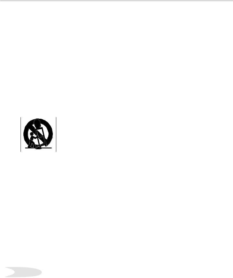
 Do not place the TV on an unstable cart, stand, tripod, or table. The TV may fall, causing serious injury to a child or adult and serious damage to the TV. Use only with a cart, stand, tripod, bracket, or table recommended by the manufacturer, or sold with the TV. Any mounting of the TV should follow the manufacturer’s instructions, and should use mounting accessories recommended by the manufacturer.
An appliance and cart combination should be moved with care. Quick stops, excessive force, and uneven surfaces may cause the appliance and cart combination to overturn.
7.Ventilation
Slots and openings in the cabinet are provided for ventilation and to ensure reliable operation of the TV and to protect it from overheating. Do not block these openings or allow them to be obstructed by placing the TV on a bed, sofa, rug, or other similar surface. Nor should it be placed over a radiator or heat register. If the TV is to be placed in a rack or bookcase, ensure that there is adequate ventilation and that the manufacturer’s instructions have been adhered to.
8.Power Source
This TV should be operated only from the type of power source indicated on the marking label. If you are not sure of the type of power supplied to your home, consult your appliance dealer or local power company.
9. Grounding or Polarization
This TV is equipped with a polarized alternating current line plug having one blade wider than the other. This plug will fit into the power outlet only one way. If you are unable to insert the plug fully into the outlet, try reversing the plug. If the plug should still fail to fit, contact your electrician to replace your obsolete outlet. Do not defeat the safety purpose of the polarized plug.
10.Power-Cord Protection
Power-supply cords should be routed so that they are not likely to be walked on or pinched by items placed upon or against them, paying particular attention to cords at plugs, convenience receptacles, and the point where they exit from the TV.
11.Lightning
For added protection for this TV during a lightning storm, or when it is left unattended and unused for long period of time, unplug it from the wall outlet and disconnect the antenna or cable system. This will prevent damage to the TV due to lightning and power-line surges.
4
IMPORTANT SAFEGUARDS, cont’d.
12.Power Lines
An outside antenna system should not be located in the vicinity of overhead power lines or other electric light or power circuits, or where it can fall into such power lines or circuits. When installing an outside antenna system, extreme care should be taken to keep from touching such power lines or circuits as contact with them might be fatal.
13.Overloading
Do not overload wall outlets and extension cords as this can result in a risk of fire or electric shock.
14.Object and Liquid Entry
Never push objects of any kind into this TV through openings as they may touch dangerous voltage points or short-out parts that could result in fire or electric shock. Never spill liquid of any kind on or into the TV.
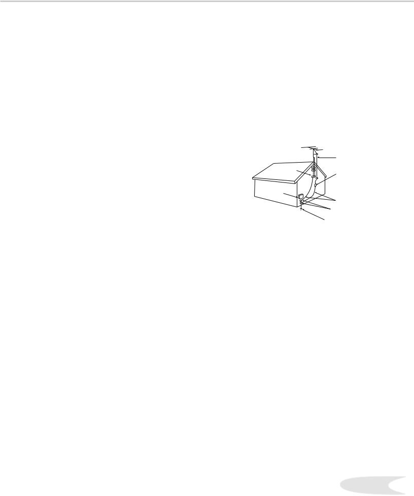
15.Outdoor Antenna Grounding
If an outside antenna or cable system is connected to the TV, be sure the antenna or cable system is grounded so as to provide some protection against voltage surges and built-up static charges.
Section 810 of the National Electric Code, ANSI/NFPA No. 701984, provides information with respect to proper grounding of the mast and supporting structure, grounding of the lead in wire to an antenna discharge unit, size of grounding conductors, location of antenna discharge unit, connection to grounding electrodes, and requirements for the grounding electrode.
EXAMPLE OF ANTENNA GROUNDING
|
ANTENNA |
|
|
LEAD IN WIRE |
|
GROUND CLAMP |
|
|
|
ANTENNA |
|
|
DISCHARGE UNIT |
|
ELECTRIC |
(NEC SECTION 810-20) |
|
|
||
SERVICE |
GROUNDING |
|
EQUIPMENT |
||
CONDUCTORS |
||
|
||
|
(NEC SECTION 810-21) |
|
|
GROUND CLAMPS |
|
|
POWER SERVICE GROUNDING |
|
|
ELECTRODE SYSTEM |
|
NEC — NATIONAL ELECTRICAL CODE (NEC ART 250, PART H) |
||
16.Servicing
Do not attempt to service this TV yourself as opening or removing covers may expose you to dangerous voltage or other hazards. Refer all servicing to qualified service personnel.
17.Damage Requiring Service
Unplug the TV from the wall outlet and refer servicing to qualified service personnel under the following conditions:
(a)When the power-supply cord or plug is damaged.
(b)If liquid has been spilled, or objects have fallen into the TV.
(c)If the TV has been exposed to rain or water.
(d)If the TV does not operate normally by following the operating instructions, adjust only those controls that are covered by the operating instructions as an improper adjustment of other controls may result in damage and will often require extensive work by a qualified technician to restore the TV to its normal operation.
(e)If the TV has been dropped or the cabinet has been damaged.
(f)When the TV exhibits a distinct change in performance - this indicates a need for service.
18.Replacement Parts
When replacement parts are required, be sure the service technician has used replacement parts specified by the manufacturer or have the same characteristics as the original part. Unauthorized substitutions may result in fire, electric shock or other hazards.
19.Safety Check
Upon completion of any service or repair to the TV, ask the service technician to perform safety checks to determine that the TV is in safe operating condition.
20.Heat
The product should be situated away from heat sources such as radiators, heat registers, stoves, or other products (including amplifiers) that produce heat.
5

If you have questions regarding your television, call
Consumer Relations
at (800) 332-2119, or email us at
MDEAservice@bigscreen.mea.com
To order replacement or additional remote controls or owner’s guides
call (800) 553-7278
or
visit our website at www.mitsubishi-tv.com

In This Section . . . |
1 |
|
CHAPTER ONE |
||
|
8Our Thanks
9Unpacking Your New TV
9Special Features

Our Thanks...
Thank you for choosing Mitsubishi as your premier Home Entertainment provider.
This Owner’s Guide describes the features and functions of your Mitsubishi widescreen, high definition TV. We urge you to examine this Owner’s Guide to become familiar with the innovative features and operations this unique television offers.
The very core of our corporate philosophy is to provide our customers with the very best. Our development team at Mitsubishi has worked to provide you with a television that defines “state-of-the-art,” with the capability to meet your needs now and in the future.
Whether this is your first Mitsubishi electronic product, or an addition to your Mitsubishi collection, we believe you and your family will continue to enjoy your Mitsubishi home theater for many years.
Thank you,
Mitsubishi Digital Electronics America, Inc.
8
Unpacking Your New TV
Please take a moment to review the following list of items to ensure that you have received everything included:
Remote Control
(2) AA Batteries
(1) Digital Audio Cable
4 (1) Double IR Emitter Cable
5 (1) Quadruple IR Emitter Cable
6 Product Registration Card
7 Owner’s Guide
8Quick Reference Card
NetCommand™ 2.0 Guide
1.Remote Control
2.(Two) AA Batteries
3. (One) Digital Audio Cable
4. (One) Double IR Emitter Cable
Special Features
Your new High Definition bigscreen television has many special features that make it the perfect center of your home entertainment system. Below we have highlighted a handful.
Fully Integrated HDTV
Your Mitsubishi bigscreen TV can receive all approved terrestrial broadcast digital signals, nonscrambled digital cable signals, terrestrial analog signals and non-scrambled analog cable signals that use a standard offset carrier system. Further, your TV will display all High Definition signals as 1080i True HDTV™ and all standard definition signals will be displayed as 480p.
NetCommand™ Home Network Control System
Your Mitsubishi bigscreen HDTV offers a new level of networking to combine selected older products with new and future digital products.
NetCommand™ supports IEEE 1394 connections, HAVi (Home Audio Video Interoperability) Control system, Audio Video Control system (AV/C), 5C copy protection and IR control of selected older products such as VCRs, DVD players, cable boxes or satellite receivers. All operating in a similar manner using on-screen graphical menus and a single remote control. See the NetCommand™ 2.0 Guide for instructions on how to use this feature.
Wide Screen Picture Format
Enjoy a full theatrical experience in the comfort of your home. View pictures as film directors intended them. Both DTV and DVD support the widescreen format well-suited for your new TV.
PIP/POP Viewing Option
Using Picture-in-Picture and Picture-outside-Picture
will give you exciting options for viewing your
favorite programs.
V-Chip Technology
Your Mitsubishi bigscreen will allow you to restrict viewing of programming by general content, category contents, or even by time.
5. (One) Quadruple IR Emitter Cable
9

In This Section . . . |
2 |
|
CHAPTER TWO |
||
|
12Front Control Panel
13Back Panel
15External Devices & NetCommand™
16Supported Devices
17Antenna or Wall Outlet Cable for Digital Broadcasts
17 Analog Antenna, Wall Outlet Cable, or Cable Box
19 Analog VCR
20Audio/Video Surround Sound Receiver
21DVD Player
21S-Video Satellite Receiver
22External Digital TV (DTV or HDTV) Receiver (YPbPr)
23DTV or HDTV- (RGB)
24Computer with a VGA Monitor Output
24IR-Home Theater Control and IR - Repeater
25Important Notes: Stationary Images
26NetCommand™ Setup - Getting Started
27Programming the Remote Control
28NetCommand™ Setup
32 Edit NetCommand™
Front Control Panel |
|
|
|
|
|
|||
|
|
|
|
|
|
|
|
|
|
||||||||
|
||||||||
|
|
|
|
|
|
|
|
|
|
|
|
|
|
|
|
|
|
|
|
|
|
|
|
|
|
|
|
|
|||||||
|
|
|
|
|
|
|
|
|
|
|
|
|
|
|
|
|
|
|
|
|
|
|
|
|
|
|
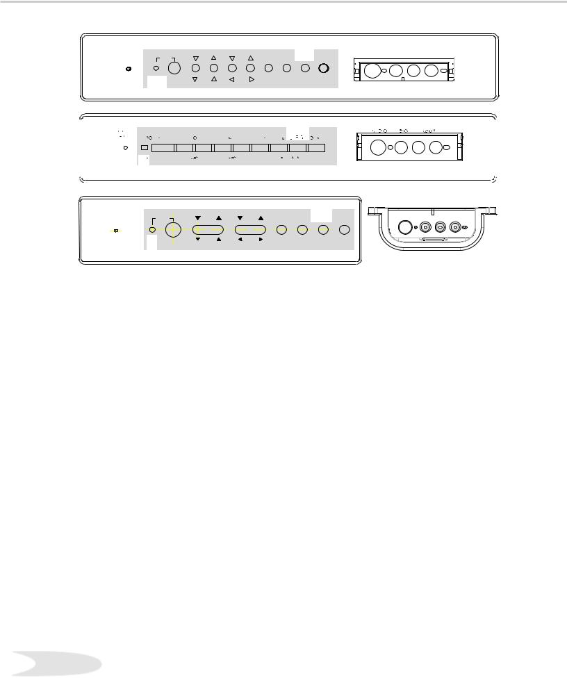
The buttons on the Front Control Panel highlighted in gray are duplicated on the remote control. The top row of labels show the control functions when there are no TV menus displayed on the screen. The
bottom row of labels show the control functions when the TV menus are displayed on the screen or when a special function has been activated. See Remote Control Functions: Overview, for further details on the functions of these buttons.
System Reset
If the TV will not respond to either the remote control or the front panel controls and will not power off, press the SYSTEM RESET button with a pointed item like the end point of a paperclip. The TV turns Off and the TIMER light flashes quickly for about one minute. When the TIMER light stops flashing, you may turn on the TV again. The changes you made while the TV was On before you used the SYSTEM RESET button may be cancelled, however, the changes you made previously are not cancelled.
Power/Timer
The green light is a multi-function indicator. Each time the TV is plugged into the wall electrical outlet, when power is restored after a power failure, or after using the SYSTEM RESET button, this light will flash rapidly for about one minute. Do not attempt to turn on the TV during this period. Wait for the flashing to stop before attempting to turn the TV on. While the TV is powered on, the light illuminates steadily. If the TV has been programmed to turn on automatically using the Timer feature, this light will flash slowly while the TV is powered off.
A/V Reset
Press this button to reset all A/V memories to the factory default settings.
Input 5
This input can be used for convenient connection of a camcorder or other video device to the TV. Please note that if you connect to the S-VIDEO terminal, the VIDEO terminal is deactivated. The VIDEO terminal is active when there is no S-Video connection.
12
Back Panel
Inputs 1-4
These inputs can be used for the connection of a VCR, Super VHS (S-VHS) VCR, DVD player, standard satellite receiver or other A/V device to the TV. Please note that if you connect to the S-VIDEO terminal, the VIDEO terminal is deactivated. The VIDEO terminal is active when there is no S-Video connection.
Output (Monitor and PIP)
The Monitor Output sends the TV audio and video signals from Ant-A, Ant-B and Inputs 1-5 to an A/V Receiver or other analog A/V equipment. Monitor Output will also provide the signals, converted to analog signals, received from Ant-DTV and IEEE-1394 products. There will be no video signals from digital products if the original signals are copy protected.
From VGA, Component 1 and 2 and Input-DTV, no signals will be sent. The PIP output sends the PIP’s or POP’s audio signal to an amplifier or wireless headphones. If no PIP or POP is displayed, the PIP output will not send any audio.
Antenna (ANT-A, LOOP OUT, and ANT-B)
ANT-A and ANT-B receive analog NTSC signals from VHF/UHF antennas or an analog NTSC cable system. LOOP OUT sends the ANT-A signal out to another component, such as a cable box or VCR.
4 IR Emitter-Repeater
Connecting IR emitters here allows the TV to pass IR commands from most IR remote controls to other A/V devices that are out of range of the remote control.
5 VGA
This input can be used for the connection of a computer. Please see Appendix B for signal compatibility.
6 Component Inputs 1-2
These inputs can be used for the connection of A/V equipment with component video outputs, such as a DVD player. Please see Appendix B for signal compatibility.
7 DTV Input
This input is used to connect an external DTV receiver, and can be configured for HDTV signal types component (YPrPb), RGB sync on green, and RGB plus H&V. Please see Appendix B for signal compatibility.
13
Back Panel
8 Antenna DTV (ANT-DTV)
This input receives digital TV signals from a VHF/UHF antenna or unscrambled digital cable system. If the TV receives scrambled cable signals on this input, it will not be able to decode them. In this case, your cable company must provide a decoding box.
9 IEEE-1394 Input/Output
These jacks allow the TV to connect to one or more external digital products by means of a single cable. Three jacks are provided for this purpose, which allow for a high degree of flexibility for connecting your system together. Please refer to the NetCommand™ Guide for IEEE-1394 device connection details.
10 Digital Audio Output
This output provides digital audio streams, such as Dolby Digital, PCM or MPEG digital audio, received in the signal from the ANT-DTV input or the IEEE-1394 devices. This output is intended to be connected to an external audio receiver that is capable of decoding the digital streams and converting them to analog signals suitable for driving loudspeakers. This output does not send a signal while analog devices connected to other inputs are being used.
11 IR Emitter-Home Theater Control Output
Two jacks are provided for connecting IR emitters. IR Emitters connected to these jacks are used by the NetCommand™ system of the TV to control external analog devices such as VCRs, DVDs, cable boxes satellite receivers and audio receivers.
12 Memory Card
The card slot behind the cover allows the software of the TV to be updated with expanded features by use of a compact flash card provided by Mitsubishi. The TV does not come with a card and does not require a card when it is first received. You should not attempt to use a flash card that is not authorized by Mitsubishi or insert any other item into this slot as this may cause damage to your TV that is not covered by your warranty. When software updates are available, they will be announced on our web site, www.mitsubishitv.com. If you return your Owner’s Registration card with your model and serial number, you may receive written notification of available software updates.
14
Connecting External Devices & NetCommand™ Setup
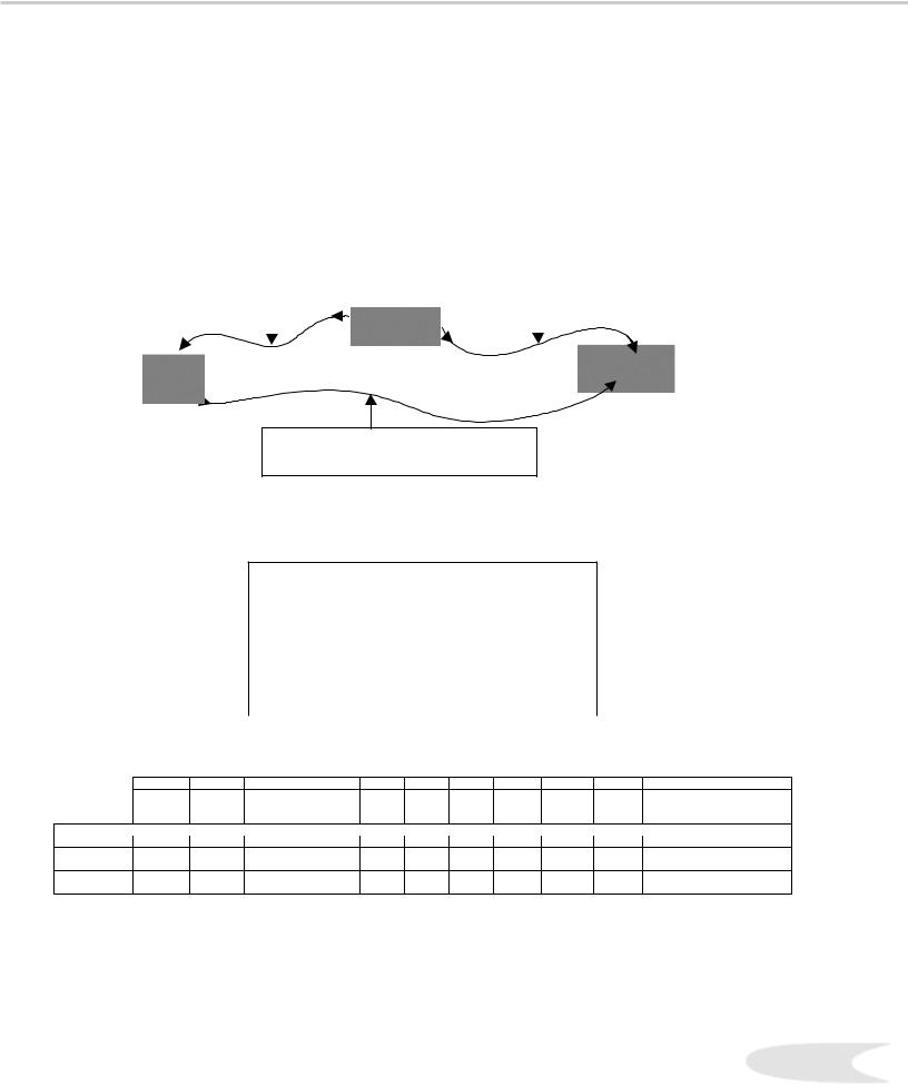
NetCommand™ is able to control many current audio and video devices by sending remote control signals from the TV to each device. NetCommand™ will also automatically switch the TV and compatible Audio/ Video (A/V) Receivers to the correct input used with each device. It is important that the inputs on the TV and AV Receiver match the NetCommand™ Setup.
To simplify the installation of NetCommand™, there is a step-by-step on-screen NetCommand™ Setup procedure. This procedure details the type and brands of devices you are connecting to the TV. The NetCommand™ Setup also assigns preset TV and AV Receiver inputs for each device. You should connect each device to the TV input (both audio and video) and to the AV Receiver (audio) as shown in Figure 1.
|
|
|
|
|
|
|
|
|
|
|
|
|
||
|
|
|
|
|
|
|
|
|
|
|
|
|
|
|
|
|
|
|
||
|
Figure 1. Connecting each Device
The following charts show which preset inputs you should use on the TV and AV Receiver. Chart 1 shows TV inputs. Chart 2 shows the AV Receiver inputs.
Device Audio and Video Outputs to TV Inputs
Antenna/Cable (analog) |
Ant-A |
|
|
Antenna/Cable (digital) |
Ant-DTV |
|
|
Cable box |
Ant-B |
|
|
VCR |
Input-1 |
|
|
Satellite Receiver (DBS) |
Input-2 |
|
|
Camcorder |
Input-5 |
|
|
DVD Player |
Component-1 |
|
|
Chart 1. Device Audio/Video Outputs to TV Inputs
A/V Receiver Input by Manufacturer
|
|
|
|
|
|
|
|
|
|
|
|
|
|
|
|
|
|
|
|
|
|
|
|
|
|
|
|
|
|
|
|
|
|
|
|
|
|
|
|
|
|
|
|
|
|
|
|
|
|
|
|
|
|
|
|
|
|
|
|
|
|
|
|
|
|
|
|
|
|
|
|
|
|
|
|
|
|
|
|
|
|
|
|
|
|
|
|
|
|
|
|
|
|
|
|
|
|
|
|
|
|
|
|
|
|
|
|
|
|
|
|
|
|
|
|
|
|
|
|
|
|
|
|
|
|
|
|
|
|
|
|
|
|
|
|
|
|
|
|
Chart 2. AV Receiver Inputs
NetCommand™ Setup provides an edit option so you may delete a type of product you do not have, change the inputs you used for connecting each device or add devices not included in the presets above. See Editing NetCommand™ Setup later in this chapter. See Connection Helpful Hints, inside back cover, for additional information.
15

NetCommand™ Supported Devices
Following is a list of devices, by several manufacturers, tested and shown to be compatible with the NetCommand™ control system. When you use these devices you will be able to control them without changing the setting of the remote control from TV to another product.
NetCommand™ Compatible Legacy Devices
|
|
|
|
|
|
|
|
|
|
|
|
|
|
|
|
|
|
|
|
|
|
|
|
|
|
|
|
|
|
|
|
|
|
|
|
|
|
|
|
|
|
|
|
|
|
|
|
|
|
|
|
|
|
|
|
|
|
|
|
|
|
|
|
|
|
|
|
|
|
|
|
|
|
|
|
|
|
|
|
|
|
|
|
|
|
|
|
|
|
|
|
|
|
|
|
|
|
|
|
|
|
|
|
|
|
|
|
|
|
|
|
|
|
|
|
|
|
|
|
|
|
|
|
|
|
|
|
|
|
* XBox™ requires the DVD kit from Microsoft
** Playstation® 2 requires the DVD Remote Controller kit from Sony; DVD Player software disc version 2.10
NetCommand™ may be able to operate additional models since many manufacturers use the same control signals to operate some or all of the models they offer. The above chart lists only the models that have been tested with NetCommand™. For each Manufacturer, models other than specified above may be compatible.
For devices not supported by NetCommand™, you will need to use the original remote control of the device or program the TV remote to operate these devices in the traditional manner.
16
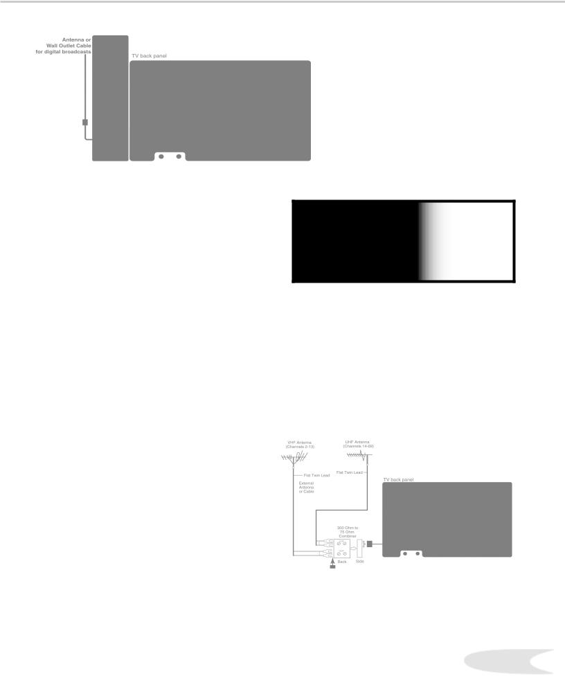
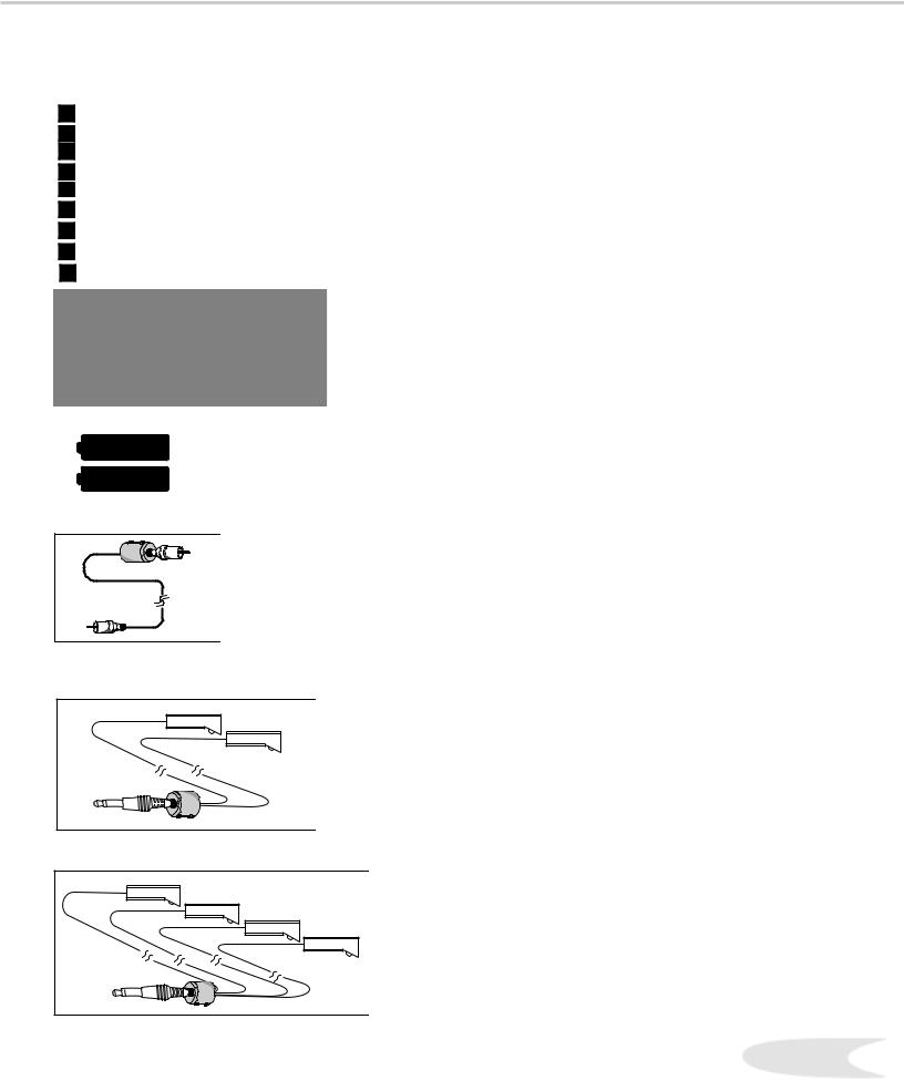
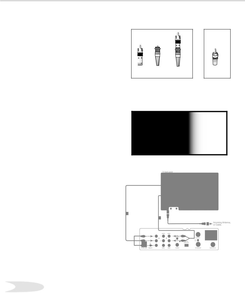
Connecting Antenna or Wall Outlet Cable for Digital Broadcasts
Figure 1. Antenna or wall outlet cable.
Antenna or Wall Outlet Cable
for Digital Broadcasts
For cable or antenna with coaxial lead (Figure 1)
1. Connect the incoming cable to ANT-DTV on the TV back panel.
Mitsubishi strongly recommends against using antennas with twin flat leads. Twin flat lead antenna wires are subject to interference which may adversely affect the performance of the TV. We recommend using coaxial antenna cable.
IMPORTANT
Additional connection cables are not provided with the TV. They are available at most electronic stores.
Connecting an Analog Antenna, Wall Outlet Cable, or Cable Box
Separate UHF and VHF Antennas
(Figure 2)
1. Connect the UHF and VHF antenna leads to the UHF/VHF combiner.
2. Push the combiner onto ANT-A on the TV back panel.
Note: UHF/VHF combiners are not provided with the TV. They should be available at most electronic stores.
Mitsubishi strongly recommends against using |
Figure 2. Connecting separate UHF and VHF antennas. |
antennas with twin flat leads. Twin flat lead antenna |
|
wires are subject to interference which may |
|
adversely affect the performance of the TV. We |
|
recommend using coaxial antenna cable. |
|
17
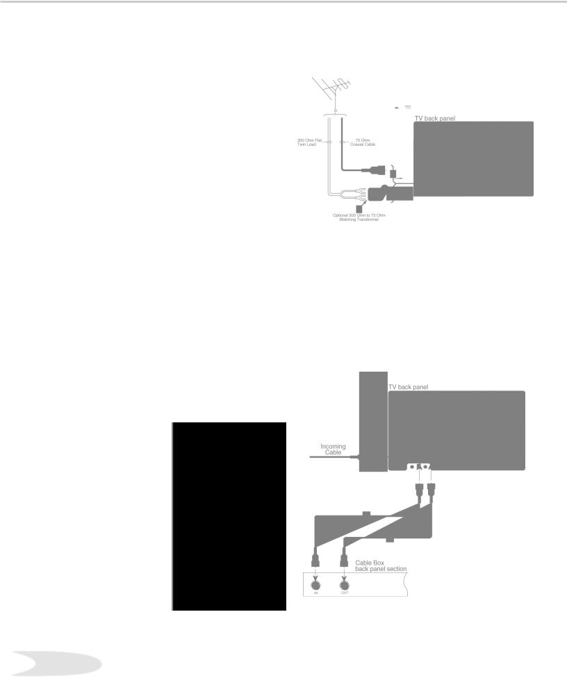
Connecting an Analog Antenna, Wall Outlet Cable, or Cable Box, cont’d.
Antenna or Wall Outlet Cable for Analog Broadcasts.
(Figure 2)
For antennas with twin flat lead
1. For antenna with twin flat leads, connect the 300Ohm twin leads to the transformer.
2. Push the 75-Ohm side of the transformer onto ANT-A on the TV back panel.
Note: 300-Ohm to 75-Ohm matching transformers are not provided with the TV. They should be available at most electronic stores.
For cable or antenna with coaxial lead
3. Connect the incoming cable to ANT-A on the TV back panel.
Mitsubishi strongly recommends against using antennas with twin flat leads. Twin flat lead antenna wires are subject to interference which may adversely affect the performance of the TV. We recommend using coaxial antenna cable.
Figure 2. Connecting antenna or wall outlet cable for analog broadcasts.
Cable Box
(Figure 3)
1. Connect the incoming cable to ANT-A on the TV back panel.
Note: Connect two coaxial cables as follows:
2.One from LOOP-OUT on the TV back panel to IN on the cable box back panel.
3.One from OUT on the cable box back panel to ANT-B on the TV back panel.
Figure 3. Connecting the cable box.
18
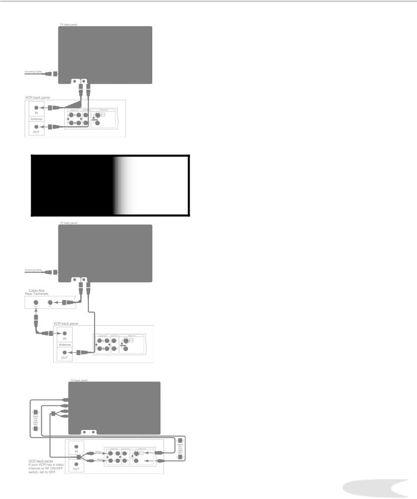
Connecting an Analog VCR
Figure 1. Connecting VCR with antennas or wall outlet cable.
IMPORTANT
Additional connection cables are not provided with the TV. They are available at most electronic stores.
Figure 2. Connecting VCR with cable box.
Figure 3. Connecting the VCR Audio/Video.
VCR to Analog Antennas or Wall Outlet Cable (Figure 1)
1. Connect the incoming cable to ANT-A on the TV back panel.
Note: Connect two coaxial cables as follows:
2.One from LOOP-OUT on the TV back panel to ANTENNA IN on the VCR back panel.
3.One from VCR back panel ANTENNA OUT to ANT-B on the TV back panel.
4.Now complete Figure 3, steps 1-2.
VCR to Cable Box (Figure 2)
1. Connect the incoming cable to ANT-A on the TV back panel.
Note: Connect three coaxial cables as follows:
2.One from LOOP-OUT on the TV back panel to IN on the back of the cable box.
3.One from OUT on the back of the cable box to ANTENNA IN on the VCR back panel.
4.One from ANTENNA OUT on the VCR back panel to ANT-B on the TV back panel.
5.Now complete Figure 3, steps 1-2.
Adding Composite Video or an S-Video with Audio Connections
(Figure 3)
1. Connect a video cable from VIDEO OUT on the VCR back panel to VIDEO INPUT 1 on the TV back panel.
Note: If you have an S-VHS VCR, follow the same steps using the S-Video terminals on the VCR and TV (in place of the composite terminals).
2. Connect a set of audio cables from AUDIO OUT on the VCR back panel to AUDIO INPUT 1 on the TV back panel. The red cable connects to the R (right) channel and the white cable connects to the L (left) channel. If your VCR is mono (non-stereo), connect only the white (left) cable.
Note: Step 2 allows the use of the TV speakers with the VCR.
Important: If you add a second VCR or use any other inputs for your VCR, see the section on Editing NetCommand™ Setup to ensure this change matches the NetCommand™ system.19
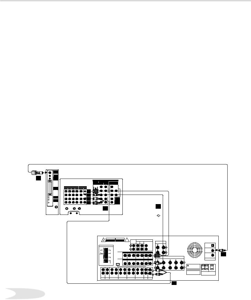
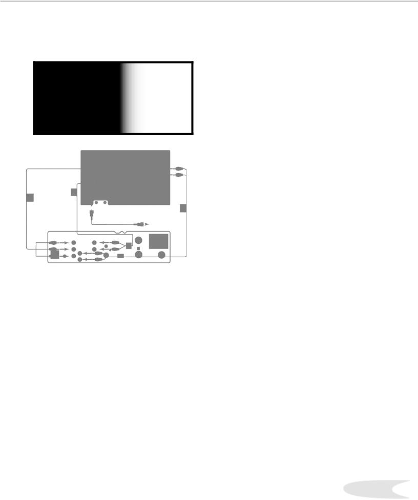
Connecting an Audio/Video Surround Sound Receiver
Connecting an A/V Receiver
(Figure 1)
1. Connect a video cable from Monitor VIDEO OUTPUT on the back of the TV to the TV VIDEO INPUT on the back of the A/V Receiver.
Note: If you have connected an S-VHS VCR to the A/V Receiver, then follow the same video connection using the S-Video cable and terminals on the TV and A/V Receiver (instead of the VIDEO cable).
2. Connect a set of audio cables from the Monitor AUDIO OUTPUT on the back of the TV to the TV AUDIO INPUT on the back of the A/V Receiver. The red cable connects to the R (right) channel and the white cable connects to the L (left) channel.
When you connect a digital A/V Receiver with Dolby DigitalTM surround sound:
3. Connect one end of the digital audio cable supplied with the TV to the DIGITAL AUDIO OUTPUT on the back of the TV (connect the end of the cable with the ferrite or plastic cylinder). Connect the other end to the COAXIAL DIGITAL INPUT on the back of the A/V Receiver. Check the Owner’s Guide for
the A/V Receiver for information concerning the use of the digital input and switching between the digital sound and analog stereo sound from the TV.
Note: Video connections shown are used primarily for recording to a VCR connected to the A/V Receiver.
|
|
|
|
|
|
|
|
|
|
|
|
|
|
|
|
|
|
|
|
|
|
|
|
|
|
|
|
|
|
|
|
|
|
|
|
|
|
|
|
|
|
|
|
|
|
|
|
|
|
|
|
|
|
|
|
|
|
|
|
|
|
|
|
|
|
|
|
|
|
|
|
|
|
|
|
|
|
|
|
|
|
|
|
|
|
|
|
|
|
|
|
|
|
|
|
|
|
|
|
|
|
|
|
|
|
|
|
|
|
|
|
|
|
|
|
|
|
|
|
|
|
|
|
|
|
|
|
|
|
|
|
|
|
|
|
|
|
|
|
|
|
|
|
||||||||||||
|
|
|
|
|
|
|
|
|
|
|
|
|
|
|
|
|
|
|
|
|
|
|
|
|
||
|
|
|
|
|
|
|
|
|
|
|
|
|
|
|
|
|
|
|
|
|
|
|
|
|
|
|
|
|
|
|
|
|
|
|
|
|
|
|
|
|
|
|
|
|
|
|
|
|
|
|
|
|
|
|
|
|
|
|
|
|
|
|
|
|
|
|
|
|
|
|
|
|
|
|
|
|
|
|
||
|
|
|
|
|
|
|
|
|
|
|
|
|
|
|
|
|
|
|
|
|
|
|
|
|
|
|
|
|
|
|
|
|
|
|
|
|
|
|
|
|
|
|
|
|
|
|
|
|
|
|
|
|
|
|
|
|
|
|
|
|
|
|
|
|
|
|
|
|
|
|
|
|
|
|
|
|
|
|
|
|
|
|
|
|
|
|
|
|
|
|
|
|
|
|
|
|
|
|
|
|
|
|
|
|
|
|
|
|
|
|
|
|
|
|
|
|
|
|
|
|
|
|
|
|
|
|
|
|
|
|
|
|
|
|
|
|
|
|
|
|
|
|
|
|
|
|
|
|
|
|
|
|
|
|
|
|
|
|
|
|
|
|
|
|
|
|
|
|
|
|
|
|
|
|
|
|
|
|
|
|
|
|
|
|
|
|
|
|
|
|
|
|
|
|
|
|
|
|
|
|
|
|
|
|
|
|
|
|
|
|
|
|
|
|
|
|
|
|
|
|
|
|
|
|
|
|
|
|
|
|
|
|
|
|
|
|
|
|
|
|
|
|
|
|
|
|
|
|
|
|
|
|
|
|
|
|
|
|
|
|
|
|
|
|
|
|
|
|
|
|
|
|
|
|
|
|
|
|
|
|
|
|
|
|
|
|
|
|
|
|
|
|
|
|
|
|
|
|
|
|
|
|
|
|
|
|
|
|
|
|
|
|
|
|
|
|
|
|
|
|
|
|
|
|
|
|
|
|
|
|
|
|
|
|
|
|
|
|
|
|
|
|
|
|
|
|
|
|
|
|
|
|
|
|
|
|
|
|
|
|
|
|
|
|
|
|
|
|
|
|
|
|
|
|
|
|
|
|
|
|
|
|
|
|
|
|
|
|
|
|
|
|
|
|
|
|
|
|
|
|
|
|
|
|
|
|
|
|
|
|
|
|
|
|
|
|
|
|
|
|
|
|
|
|
|
|
|
|
|
|
|
|
|
|
|
|
|
|
|
|
|
|
|
|
|
|
|
|
|
|
|
|
|
|
|
|
||
|
|
|
|
|
|
|
|
|
|
|
|
|
|
|
|
|
|
|
|
|
|
|
|
|||
|
|
|
|
|
|
|
|
|
|
|
|
|
|
|
|
|
|
|
|
|
|
|
|
|
||
|
|
|
|
|
|
|
|
|
|
|
|
|
|
|
|
|
||||||||||
|
|
|
|
|
|
|
|
|
|
|
|
|
|
|
|
|
|
|
|
|
|
|
|
|
|
|
|
|
|
|
|
|
|
|
|
|
|
|
|
|
|
|
|
|
|
|
|
|
|
||||
|
|
|
|
|
|
|
|
|
|
|
|
|
|
|
|
|
|
|
|
|
|
|||||
|
|
|
|
|
|
|
|
|
|
|
|
|
|
|
|
|
|
|
|
|
|
|
|
|||
|
|
|
|
|
|
|
|
|
|
|
|
|
|
|
|
(6Ω |
) |
|
|
|
|
|
||||
|
|
|
|
|
|
|
|
|
|
|
|
|
|
|
|
|
|
|
|
|
|
|
|
|
||
|
|
|
|
|
|
|
|
|
|
|
|
|
|
|
|
|
|
|
|
|
|
|
||||
|
|
|
|
|
|
|
|
|
|
|
|
|
|
|
|
|
|
|
|
|
|
|||||
|
|
|
|
|
|
|
|
|
|
|
|
|
|
|
|
|
|
|
|
|
|
|
||||
|
|
|
|
|
|
|
|
|
|
|
|
|
|
|
|
|
|
|
|
|
|
|
|
|||
|
|
|
|
|
|
|
|
|
|
|
|
|
|
|
|
|
|
|
|
|
|
|
|
|
||
|
|
|
|
|
|
|
|
|
|
|
|
|
|
|
|
|
|
|
|
|
|
|
|
|
||
|
|
|
|
|
|
|
|
|
|
|
|
|
|
|
|
|
|
|
|
|
|
|
|
|||
|
|
|
|
|
|
|
|
|
|
|
|
|
|
|
|
|
|
|
|
|
|
|
|
|
|
|
|
|
|
|
|
|
|
|
|
|
|
|
|
|
|
|
|
|
|
|
|
|
|
|
|
||
|
|
|
|
|
|
|
|
|
|
|
|
|
|
|
|
|
|
|
|
|
|
|
|
|
|
|
|
|
|
|
|
|
|
|
|
|
|
|
|
|
|
|
|
|
|
|
|
|
|
|
|
|
|
|
|
|
|
|
|
|
|
|
|
|
|
|
|
|
|
|
|
|
|
|
|
|
|
|
||
|
|
|
|
|
|
|
|
|
|
|
|
|
|
|
|
|
|
|
|
|
|
|
||||
|
|
|
|
|
|
|
|
|
|
|
(6Ω |
) |
(6Ω |
) |
(6Ω |
) |
|
|
|
|
||||||
|
|
|
|
|
|
|
|
|
|
|
|
|
|
|
|
|||||||||||
|
|
|
|
|
|
|
|
|
|
|
|
|
|
|
|
|
||||||||||
|
|
|
|
|
|
|
|
|
|
|
|
|
|
|
|
|
|
|
|
|
|
|
|
|
|
|
|
|
|
|
|
|
|
|
|
|
|
|
|
|
|
|
|
|
|
|
|
|
|
|
|
||
|
|
|
|
|
|
|
|
|
|
|
|
|
|
|
|
|
|
|
|
|
|
|
|
|
|
|
|
|
|
|
|
|
|
|
|
|
|
|
|
|
|
|
|
|
|
|
|
|
|
|
|
|
|
|
|
|
|
|
|
|
|
|
|
|
|
|
|
|
|
|
|
|
|
|
|
|
|
|
|
|
|
|
|
|
|
|
|
|
|
|
|
|
|
|
|
|
|
|
|
|
|
|
|
|
|
|
|
|
|
|
|
|
|
|
|
|
|
|
|
|
|
|
|
|
|
|
|
|
|
|
|
|
||
|
|
|
|
|
|
|
|
|
|
|
|
|
|
|
|
|
|
|
|
|
|
|
|
|
|
|
|
|
|
|
|
|
|
|
|
|
|
|
|
|
|
|
|
|
|
|
|
|
|
|
|
|
|
|
|
|
|
|
|
|
|
|
|
|
|
|
|
|
|
|
|
|
|
|
|
|
|
|||
|
|
|
|
|
|
|
|
|
|
|
|
|
|
|
|
|
|
|
|
|
|
|
|
|
|
|
|
|
|
|
|
|
|
|
|
|
|
|
|
|
|
|
|
|
|
|
|
|
|
|
|
||
|
|
|
|
|
|
|
|
|
|
|
|
|
|
|
|
|
|
|
|
|
|
|
|
|
||
|
|
|
|
|
|
|
|
|
|
|
|
|
|
|
|
|
|
|
|
|
|
|
|
|
|
|
|
|
|
|
|
|
|
|
|
|
|
|
|
|
|
|
|
|
|
|
|
|
|
|
|
||
|
|
|
|
|
|
|
|
|
|
|
|
|
|
|
|
|
|
|
|
|
|
|
|
|
|
|
|
|
|
|
|
|
|
|
|
|
|
|
|
|
|
|
|
|
|
|
|
|
|
|
|
||
|
|
|
|
|
|
|
|
|
|
|
|
|
|
|
|
|
|
|
|
|
|
|
|
|
|
|
|
|
|
|
|
|
|
|
|
|
|
|
|
|
|
|
|
|
|
|
|
|
|
|
|||
|
|
|
|
|
|
|
|
|
|
|
|
|
|
|
|
|
|
|
|
|
|
|
|
|
|
|
20
WARNING: Do not display the same stationary images on the screen for more that 15% of your total TV viewing in one week. Examples of stationary images are letterbox top/bottom bars from DVD or other video sources, side bars when showing standard TV pictures on widescreen TV’s, stock market reports, video game patterns, station logos, black or bright Closed caption backgrounds web sites, or stationary computer images. Such patterns can unevenly age the picture tubes causing permanent damage to the TV.
Connecting a DVD Player
IMPORTANT
•See Appendix B for component video signal compatibility information.
•For digital audio connections, see your A/V Receiver, DVD , and Satellite Receiver Owner’s Guides.
Connecting an S-Video
Satellite Receiver
Figure 2. Connecting an S-Video Device.
DVD Player with Component Video
(Figure 1)
1. Connect the Component Video cables from Y/ Cr/Cb or Y/Pr/Pb VIDEO OUT on the back of the DVD player to COMPONENT-1 on the TV back
panel, matching the correct connection:
•Y to Y
•Cr or Pr to Pr
•Cb or Pb to Pb
2.Connect a set of audio cables from AUDIO OUT on the back of the DVD player to COMPONENT-1 AUDIO Input on the TV back panel. The red cable connects to the R (right) channel, and the white cable connects to the L (left) channel.
Important: If you add a second DVD or use any other inputs for your DVD, see the section on Editing NetCommand™ Setup to ensure this change is matched by the NetCommand™ system.
S-Video Satellite Receiver
(Figure 2)
1. Connect an S-Video cable from VIDEO OUT on the satellite receiver back panel to VIDEO INPUT-2 on the TV back panel.
2. Connect a set of audio cables from AUDIO OUT on the satellite receiver back panel to the AUDIO INPUT-2, on the TV back panel. The red cable connects to the R (right) channel and the white cable connects to the L (left) channel.
Note: Refer to the Satellite Receiver Owner’s Guide for Dish Antenna connections.
Important: If you add a second Satellite Receiver or use any other inputs for your Satellite Receiver, see the section on Editing NetCommand™ Setup to ensure this change is matched by the NetCommand™ system.
21
Connecting an External Digital TV (DTV or HDTV) Receiver
DTV Connectors and Adaptors
(Figure 1)
The TV back panel has 5 RCA-type connectors for the Input-DTV. The back panel of your external DTV receiver may use RCA-type connectors
or BNC-type connectors. If your DTV receiver comes with BNC type connections, you will need to purchase BNC to RCA adaptors to connect the TV to the DTV receiver. These adaptors should be available at most electronic supply stores.
External DTV Receiver with Component Video Connections
(Figure 2)
1. Connect the outside antenna, cable, or satellite to ANT, or SATELLITE IN on the DTV receiver (see your DTV receiver’s owner’s guide for instructions, and cable compatibility).
2.Connect the incoming terrestrial antenna, or cable (not satellite) to ANT-A on the TV back panel (a coaxial splitter, available at most electronic supply stores, may be required to complete this installation).
3.Connect RCA-type cables from the YPrPb outputs on the DTV receiver to Input-DTV on the TV back panel, matching the correct connections: (Y to Y) (Pr to Pr) (Pb to Pb).
DTV Receiver/TV Back panel
•Y to Y
•Pr to Pr
•Pb to Pb
Note: You may need to set the Input-DTV assignment to Y/Pr/Pb instead of RGB. Refer to the Edit NetCommand™ Setup for instructions on changing this setting.
4. Connect the L (left) and R (right) audio cables from the DTV receiver to Input-DTV AUDIO on the TV back panel.
Note: To utilize the benefits of a digital A/V receiver, connect your DTV receiver’s digital audio out to a digital input on your digital A/V receiver.
|
|
|
or |
BNC to |
|
Adaptor |
RCA |
RCA |
BNC |
Fitted to |
Connector |
Adaptor |
Connector |
Connection |
|
Figure 1. DTV connectors and adaptors.
IMPORTANT
•See Appendix B for component video signal compatibility information.
•For digital audio connections, see your DTV Receiver and A/V Receiver Owner’s Guides.
Figure 2. Connecting the DTV receiver with component video connections.
22
Connecting an External Digital TV (TV or HTV) Receiver, cont.
IMPORTANT
•See Appendix B for RGB video signal compatibility information.
•For digital audio connections, see your DTV Receiver and A/V Receiver Owner’s Guides.
Figure 1. Connecting the DTV receiver with RGB video
External DTV Receiver with RGB Video Connections
(Figure 1)
1. Connect the outside antenna, cable, or satellite to ANT, or SATELLITE IN on the DTV receiver (see your DTV receiver owner’s guide for instructions, and cable compatibility).
2.Connect the incoming terrestrial antenna, or cable (not satellite) to ANT-A on the TV back panel (a coaxial splitter, available at most electronic supply stores, may be required to complete this installation).
3.Connect RGB cables for the DTV receiver to Input-DTV on the TV back panel.
Note: You may need to set the Input-DTV assignment to RGB instead of Y/Pr/Pb. Refer to the Edit NetCommand™ Setup for instructions on changing this setting.
DTV Receiver / TV Back Panel
•G (green) to Y/G
•R (red) to Pr/R
•B (blue) to Pb/B
Note: If the DTV receiver has outputs for H and V sync, connect as listed below (DO NOT connect if DTV receiver uses “Sync on Green”
•H (horizontal sync) to H
•V (vertical sync) to V
4. Connect the L (left) and R (right) audio cables from the DTV receiver to Input-DTV AUDIO on the TV back panel.
23
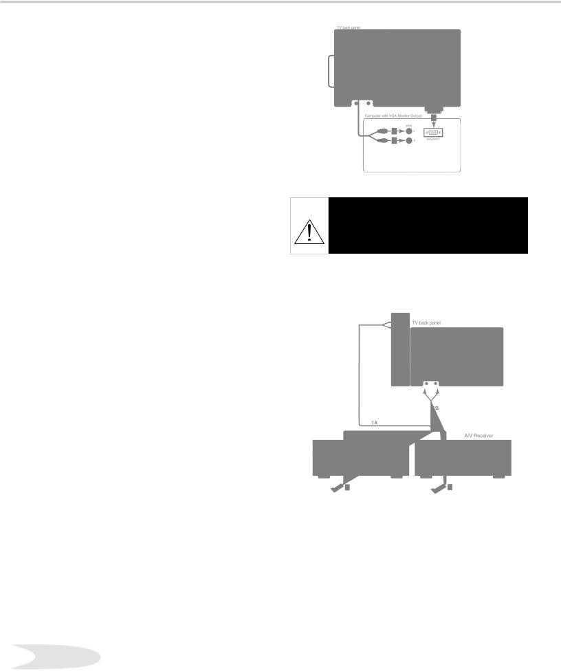
Connecting a Computer with a VGA Monitor Output
Connecting a Computer
(Figure 1)
1. Connect VGA Monitor Out from the computer to VGA Input on the TV back panel using a VGA compatible monitor cable. See Appendix B for VGA signal compatibility.
2. Connect the L (left) and R (right) audio cables from the computer to VGA AUDIO on the TV back panel. In cases where your
computer’s audio output is a single minijack, a splitter is needed to complete this connection.
Note: To utilize the benefits of a digital A/V receiver, connect your computer’s digital audio out, if available, to a digital input on your digital A/V receiver.
Connecting the IR-Home Theater Control and IR Repeater
(Figure 2)
IR Emitter-Home Theater Control
These emitters are not IR repeaters; they are used by the NetCommand™ feature to control supported devices.
1A. Connect the IR emitter to IR Emitter-Home Theater Control on the TV back panel.
OR ...
IR Emitter-Repeater
These emitters are not used by NetCommand™, but will repeat any IR command received by the TV. These emitters allow the TV to be the remote control sensor for other devices outside the range of the hand-held remote control. Do not use these repeaters with devices that can receive the remote control signal directly, as the signals can interfere
with each other.
1B. Connect the IR emitter to IR EMITTERREPEATER on the TV back panel.
Steps 2-4 (Apply both 1A and 1B)
2. Place the IR emitter cable under or along the side of the A/V device. Place the IR lens directly in front of the A/V device’s infrared signal receiver. Infrared signal receivers are usually behind the front translucent panel of the
Figure 2. Connecting the IR Home Theater Control and/ or Repeater.
3. Place unused transmitters in an out-of-the- way location.
4. For permanent installation of the IR emitter cable, use the included adhesive tape to secure the bottom of the emitter to the anchoring object of your choice.
24device.

 IMPORTANT NOTES
WARNING: When using the VGA input, do not leave stationary, toolbar, or partial images on-screen for extended periods of time. Mix the types of pictures shown. Uneven picture tube aging is NOT covered by your warranty.
The VGA capability of this television is designed for occasional use ONLY.
It is not meant to be used as a work station or to view static or odd-shaped images for an extended period of time. Any device connected to your television via the VGA port, including, but not limited to, personal computer, game system, or digital set-top box, must have its screen saver function activated to prevent damage to the television. We DO NOT recommend the use of any external device that does not have a screen saver function with this television.
We recommend that screen saver activation time be set to less than five minutes when using a device through the VGA port. You should also use lower brightness and contrast settings. If your computer programs allow, toolbars should be set to hidden mode.
Please remember most computer programs and video game systems display static images, such as boxes, buttons, tool bars, and game scores that can damage the television if used for extended periods of time, repeatedly, or frequently.
The VGA input will automatically select the “Standard” screen format and fill the screen. No other formats are available with the VGA Input. Standard television overscan is used, so VGA images will be cropped on all sides. Resizing of some displays may be required. Consult your owner’s manual for computers, computer programs and game systems for assistance with resizing display images. Please see page 70 for an explanation of uneven picture tube aging.
25

NetCommand™ Setup - Getting Started
In order to use your TV’s NetCommand™ feature, you need to provide some detailed information during the setup of your Mitsubishi TV. You must define the Manufacturer of the devices that are connected to the television. For each device, the input to the TV and A/V receiver, and the names for the device are pre-set during Initial NetCommand™ setup. You may change those inputs or names using the Edit NetCommand™ screen.
On your remote control, the ADJUST  (left) and
  (right) buttons allow you to navigate left and right to different selections on the screen. The ADJUST
  (up) and
  (down) buttons allow you to:
•Change the selected radio button
•Change selection in text boxes
•Show text boxes
The ENT (ENTer) button allows you to:
•Confirm the selected character when naming a device
•Add or delete check marks in check boxes
•Select push buttons to change screens
Radio Buttons
The setting changes when radio button is selected
Checkbox
Checkmarks indicate the item or input is added or turned On. Press ENTer when the Checkbox is highlighted to add or delete a checkmark. When viewing the Review screen, a Checkbox reflects which devices are turned On or Off, or connected to the TV.
Textbox
Buttons
Much like the software on your computer, you will use graphic buttons to navigate through the
NetCommand™ Setup screen. Highlight the button and press ENTer to select the function.
<Back Button
Use the <Back button to navigate back to the previous screen.
Next> Button
Use the Next> button to navigate forward to the next screen.
Cancel Button 
The Cancel button will cancel out any changes you are currently making without saving them into memory. When you select the Cancel button, NetCommand™ will prompt you to confirm that you want to cancel the changes you are currently making. If you select Cancel during Initial Setup, You can setup NetCommand™ later by selecting Initial on the Edit NeCommand™ menu.
Press ADJUST  (up) and
  (down) to make a selection.
26

Programming the Remote Control to Control NetCommand™
NetCommand™ |
CODE to ENTER |
|
TV Control and NetCommand™ |
935 |
|
Devices: |
|
|
|
|
|
Figure 1. Programming the TV remote to control your NetCommand™ A/V devices.
To Program the Remote to Control the TV and NetCommand™ A/V Products:
(See NetCommand™ Supported Devices, for the list of A/V products supported by the NetCommand™ System.)
1. Move the slide switch at the top of the remote to the TV layer.
2.Press and hold the POWER button on the remote control.
3.Enter the three digit code of 935, and then release the POWER button on the remote control.
4.The remote control is now programmed to send NetCommand™ signals to the TV. The
TV can also control the IEEE 1394 devices and selected NetCommand™ supported IR devices. See the NetCommand™ guide for details.
27

NetCommand™ Setup
When you first power On your new Mitsubishi TV, the initial setup screens will appear. You will need to navigate through these screens and properly set up the equipment connected to the TV in order to use NetCommand™.
NetCommand™ supports the automatic switching of audio and video inputs using only the TV Remote Control.
IMPORTANT
You may use your TV without setting up NetCommand™. You may also setup NetCommand™ at a later time by choosing Setup from the Main menu, then select Edit NetCommand™.
Language Screen
Figure 1
The Language screen is the initial menu displayed the first time the TV is turned On. You will need to select the language you would like to use. When you change your selection from English to Spanish, all screens automatically change to Spanish. To change Language later, go to Setup in the Main Menu.
Figure 1. Setup-Language screen.
Information Screen
Figure 2
The Information Screen describes how to proceed with or cancel the initial NetCommand™ Setup.
NetCommand™ Setup is initialized automatically the first |
|
time you power On your new TV. If, for any reason, your |
|
NetCommand™ Setup is cancelled before completing, |
|
follow the steps below to start NetCommand™ setup |
|
later. |
Figure 2. NetCommand™ Info screen. |
1. Display the TV Main menu. |
|
2. Select the Setup menu. |
|
3. Select the Edit NetCommand™ option in the Setup |
|
menu. |
|
4. Select Initial on the Edit NetCommand™ menu |
|
Result: The AV Receiver screen displays. |
|
28
 Loading...