


WD-62827
WD-62927
WD-73827
WD-73927
Projection Television
Owner’s Guide
TV Information
Use this space to record the model number and serial number of your television. This information is on the back of your TV.
Model Number
Serial Number
Purchase Date
TM
5.
visit our website at www.mitsubishi-tv.com
CAUTION
RISK OF ELECTRIC SHOCK |
DO NOT OPEN |
CAUTION: TO REDUCE THE RISK OF ELECTRIC SHOCK, DO NOT REMOVE COVER (OR BACK).
NO USER SERVICEABLE PARTS INSIDE. REFER SERVICING TO QUALIFIED SERVICE PERSONNEL.
The lightning flash with arrowhead symbol within an equilateral triangle is intended to alert the user of the presence of uninsulated “dangerous voltage” within the product’s enclosure that may be sufficient magnitude to constitute a risk of electric shock.
The exclamation point within an equilateral triangle is intended to alert the user to the presence of important operating and maintenance (servicing) instructions in the literature accompanying the appliance.
This TV is heavy! Exercise extreme care when lifting or moving. Lifting or moving the TV requires a minimum of two adults. To prevent damage to your TV, your TV should not be jarred or moved while it is turned on. Power off your TV before moving it.
Portions of the advanced circuitry of this TV must continue to operate even when the TV is turned off. Some of these circuits therefore need to be cooled at all times. A low power standby fan may be heard in a quiet environment. This is normal operation.
Custom cabinet installation must allow for proper air circulation around the television.
TV Guide On Screen® Access Requirements
TV Guide On Screen listings are not provided by Mitsubishi Digital Electronics America, Inc. Operation of TV Guide On Screen requires over-the-air or cable access to stations carrying TV Guide On Screen program listings. If listings are not available in your area or become discontinued by the local provider, TV Guide On Screen will not operate. TV Guide On Screen does not provide program listings for satellite TV systems.
Stand Requirement
CAUTION: Use these Mitsubishi TV models only with the Mitsubishi stand models shown here. Use with other stands can result in instability and possibly cause injury.
TV Model Number |
Stand Model Number |
|
|
WD-62827 |
MB-62827 |
WD-62927 |
MB-62927 |
|
|
WD-73827 |
MB-73827 |
|
|
WD-73927 |
MB-73927 |
|
|
LAMP REPLACEMENT
The image on this TV is produced by a powerful lamp that will operate for many hours. Eventually, however, this lamp will need to be replaced. It is designed to be easily replaced by the TV owner. Front panel indicators and/or on-screen messages will assist you in determining when the lamp needs to be replaced. Please see Appendix G for details on lamp replacement.
To order a new lamp:
While Under Warranty |
After Warranty |
|
|
Call (800) 332-2119. Please have model number, serial |
Call (800) 553-7278. Order lamp part number |
number, and TV purchase date available. |
915P027010. |
|
|
WARNING: TO REDUCE THE RISK OF FIRE OR ELECTRIC SHOCK, DO NOT EXPOSE THIS APPLIANCE TO RAIN OR MOISTURE.
CAUTION: TO PREVENT ELECTRIC SHOCK, MATCH WIDE BLADE OF PLUG TO WIDE SLOT, FULLY INSERT.
NOTE TO CATV SYSTEM INSTALLER: THIS REMINDER IS PROVIDED TO CALL THE CATV SYSTEM INSTALLER’S ATTENTION TO ARTICLE 820-40 OF THE NEC THAT PROVIDES GUIDELINES FOR THE PROPER GROUNDING AND, IN PARTICULAR, SPECIFIES THAT THE CABLE GROUND SHALL BE CONNECTED TO THE GROUNDING SYSTEM OF THE BUILDING, AS CLOSE TO THE POINT OF CABLE ENTRY AS PRACTICAL.

|
FCC Declaration of Conformity |
Product: |
Projection Television Receiver |
Models: |
WD-62827, WD-62927, WD-73827, WD-73927 |
Responsible Party: |
Mitsubishi Digital Electronics America, Inc. |
|
9351 Jeronimo Road |
|
Irvine, CA 92618-1904 |
Telephone: |
949-465-6000 |
This device complies with Part 15 of the FCC Rules. Operation is subject to the following two conditions:
(1)This device may not cause harmful interference, and
(2)this device must accept any interference received, including interference that may cause undesired operation.
Note: This equipment has been tested and found to comply with the limits for a Class B digital device, pursuant to part 15 of the FCC Rules. These limits are designed to provide reasonable protection against harmful interference in a residential installation. This equipment generates, uses and can radiate radio frequency energy and, if not installed and
used in accordance with the instructions, may cause harmful interference to radio communications. However, there is no guarantee that interference will not occur in a particular installation. If this equipment does cause harmful interference to radio or television reception, which can be determined by turning the equipment off and on, the user is encouraged to try to correct the interference by one or more of the following measures:
•Reorient or relocate the receiving antenna.
•Increase the separation between the equipment and the receiver.
•Connect the equipment into an outlet on a circuit different from that to which the receiver is connected.
•Consult the dealer or an experienced radio/TV technician for help.
CAUTION: To ensure continued FCC compliance, the user must use a shielded video interface or HDMI cable with bonded ferrite cores at both ends when using the PC input.
Changes or modifications not expressly approved by Mitsubishi could cause harmful interference and would void the user’s authority to operate this equipment.

IMPORTANT SAFEGUARDS
Please read the following safeguards for your TV and retain for future reference. Always follow all warnings and instructions marked on the television.
1.Read, Retain and Follow All Instructions
Read all safety and operating instructions before operating the TV. Retain the safety and operating instructions for future reference. Follow all operating and use instructions.
2.Heed Warnings
Adhere to all warnings on the appliance and in the operating instructions.
3.Cleaning
Unplug the TV from the wall outlet before cleaning. Do not use liquid, abrasive or aerosol cleaners. Cleaners can permanently damage the cabinet and screen. Use a lightly dampened cloth for cleaning.
4.Attachments and Equipment
Never add any attachments and/or equipment without approval of the manufacturer as such additions may result in the risk of fire, electric shock or other personal injury.
5.Water and Moisture
Do not use the TV where contact with or immersion in water is possible. Do not use near bath tubs, wash bowls, kitchen sinks, laundry tubs, swimming pools, etc.
6.Accessories
 Do not place the TV on an unstable cart, stand, tripod, or table. The TV may fall, causing serious injury to a child or adult and serious damage to the TV. Use only with a cart, stand, tripod, bracket or table recommended by the manufacturer, or sold with the TV. Any mounting of the TV should follow the manufacturer’s instructions, and should use mounting accessories recommended by the manufacturer.
An appliance and cart combination should be moved with care. Quick stops, excessive force, and uneven surfaces may cause the appliance and cart combination to overturn.
7.Ventilation
Slots and openings in the cabinet are provided for ventilation and to ensure reliable operation of the TV and to protect it from overheating. Do not block these openings or allow them to be obstructed by placing the TV on a bed, sofa, rug, or other similar surface. Nor should it be placed over a radiator or heat register. If the TV is to be placed in a rack or bookcase, ensure that there is adequate ventilation and that the manufacturer’s instructions have been adhered to.
8.Power Source
This TV should be operated only from the type of power source indicated on the marking label. If you are not sure of the type of power supplied to your home, consult your appliance dealer or local power company.
9.Grounding or Polarization
This TV is equipped with a polarized alternating current line plug having one blade wider than the other. This plug will fit into the power outlet only one way. If you are unable to insert the plug fully into the outlet, try reversing the plug. If the plug should still fail to fit, contact your electrician to replace your obsolete outlet. Do not defeat the safety purpose of the polarized plug.
10.Power-Cord Protection
Power-supply cords should be routed so that they are not likely to be walked on or pinched by items placed upon or against them, paying particular attention to cords at plugs, convenience receptacles, and the point where they exit from the TV.
11.Lightning
For added protection for this TV during a lightning storm, or when it is left unattended and unused for long period of time, unplug it from the wall outlet and disconnect the antenna or cable system. This will prevent damage to the TV due to lightning and power-line surges.
IMPORTANT SAFEGUARDS, continued
12.Power Lines
An outside antenna system should not be located in the vicinity of overhead power lines or other electric light or power circuits, or where it can fall into such power lines or circuits. When installing an outside antenna system, extreme care should be taken to keep from touching such power lines or circuits as contact with them might be fatal.
13.Overloading
Do not overload wall outlets and extension cords as this can result in a risk of fire or electric shock.
14.Object and Liquid Entry
Never push objects of any kind into this TV through openings as they may touch dangerous voltage points or short-out parts that could result in fire or electric shock. Never spill liquid of any kind on or into the TV.
15.Outdoor Antenna Grounding
If an outside antenna or cable system is connected to the TV, be sure the antenna or cable system is grounded so as to provide some protection against voltage surges and built-up static charges.
Article 810 of the National Electric Code, ANSI/NFPA No. 70-2002, provides information with respect to proper grounding of the mast and supporting structure, grounding of the lead in wire to an antenna discharge unit, size of grounding conductors, location of antenna discharge unit, connection to grounding electrodes, and requirements for the grounding electrode.
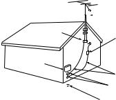
E XAMPLE OF ANTE NNA GR OUNDING
|
|
|
|
|
ANTE NNA |
|
|
|
|
|
|
|
|
|
|
|
LE AD IN WIR E |
GR OUND C LAMP |
|
|
|
||
|
|
|
|
|
ANTE NNA |
|
|
|
|
|
DIS C HAR GE UNIT |
E LE C TR IC |
|
|
(NE C AR TIC LE 810-20) |
||
|
|
|
|||
S E R VIC E |
|
GR OUNDING |
|||
E QUIPME NT |
|
||||
|
C ONDUC TOR S |
||||
|
|
|
|
||
|
|
|
|
(NE C AR TIC LE 810-21) |
|
|
|
|
|
GR OUND C LAMPS |
|
|
|
|
|
||
|
|
|
|||
|
|
|
|
POWE R S E R VIC E GR OUNDING |
|
|
|
|
|
E LE C TR ODE S YS TE M |
|
NE C — NATIONAL E LE C TR IC AL C ODE |
|
(NE C AR T 250, PAR T H) |
|||
16.Servicing
Do not attempt to service this TV yourself as opening or removing covers may expose you to dangerous voltage or other hazards. Refer all servicing to qualified service personnel.
17.Damage Requiring Service
Unplug the TV from the wall outlet and refer servicing to qualified service personnel under the following conditions:
(a)When the power-supply cord or plug is damaged.
(b)If liquid has been spilled, or objects have fallen into the TV.
(c)If the TV has been exposed to rain or water.
(d)If the TV does not operate normally by following the operating instructions, adjust only those controls that are covered by the operating instructions as an improper adjustment of other controls may result in damage and will often require extensive work by a qualified technician to restore the TV to its normal operation.
(e)If the TV has been dropped or the cabinet has been damaged.
(f)When the TV exhibits a distinct change in performance - this indicates a need for service.
18.Replacement Parts
When replacement parts are required, be sure the service technician has used replacement parts specified by the manufacturer or have the same characteristics as the original part. Unauthorized substitutions may result in fire, electric shock or other hazards.
19. Safety Check
Upon completion of any service or repair to the TV, ask the service technician to perform safety checks to determine that the TV is in safe operating condition.
20. Heat
The product should be situated away from heat sources such as radiators, heat registers, stoves or other products (including amplifiers) that produce heat.
Contents
Chapter 1: Television Overview
TV Accessories.. . . . . . . . . . . . . . . . . . . . . . . . . . . . . . . . . . . . . . . . . . . . . . . . . . . . . . . . . . . . . . . . . . . . . 10
Special Features of Your TV.. . . . . . . . . . . . . . . . . . . . . . . . . . . . . . . . . . . . . . . . . . . . . . . . . . . . . . . . . . 11
Memory Card Reader. . . . . . . . . . . . . . . . . . . . . . . . . . . . . . . . . . . . . . . . . . . . . . . . . . . . . . . . . . . . . . . . 13
Front Control Panel. . . . . . . . . . . . . . . . . . . . . . . . . . . . . . . . . . . . . . . . . . . . . . . . . . . . . . . . . . . . . . . . . . 14
Remote Control. . . . . . . . . . . . . . . . . . . . . . . . . . . . . . . . . . . . . . . . . . . . . . . . . . . . . . . . . . . . . . . . . . . . . 16
TV Back Panel.. . . . . . . . . . . . . . . . . . . . . . . . . . . . . . . . . . . . . . . . . . . . . . . . . . . . . . . . . . . . . . . . . . . . . . 18
System Reset Button.. . . . . . . . . . . . . . . . . . . . . . . . . . . . . . . . . . . . . . . . . . . . . . . . . . . . . . . . . . . . . . . . 20
Chapter 2: Connecting
External Devices and NetCommand® Setup.. . . . . . . . . . . . . . . . . . . . . . . . . . . . . . . . . . . . . . . . . . . 22 Wall Outlet Cable. . . . . . . . . . . . . . . . . . . . . . . . . . . . . . . . . . . . . . . . . . . . . . . . . . . . . . . . . . . . . . . . . . . . 23 Standard Cable Box. . . . . . . . . . . . . . . . . . . . . . . . . . . . . . . . . . . . . . . . . . . . . . . . . . . . . . . . . . . . . . . . . 23 Antenna with a Single Lead. . . . . . . . . . . . . . . . . . . . . . . . . . . . . . . . . . . . . . . . . . . . . . . . . . . . . . . . . . . 24 Antennas with Separate UHF and VHF Leads. . . . . . . . . . . . . . . . . . . . . . . . . . . . . . . . . . . . . . . . . . . 24
VCR to an Antenna or Wall Outlet Cable (Audio & Video).. . . . . . . . . . . . . . . . . . . . . . . . . . . . . . . . . 25
VCR to a Cable Box (Audio & Video). . . . . . . . . . . . . . . . . . . . . . . . . . . . . . . . . . . . . . . . . . . . . . . . . . . 26 A/V Receiver (Stereo System). . . . . . . . . . . . . . . . . . . . . . . . . . . . . . . . . . . . . . . . . . . . . . . . . . . . . . . . . 27
Satellite Receiver or Other Device with S-Video. . . . . . . . . . . . . . . . . . . . . . . . . . . . . . . . . . . . . . . . . 27
DVD Player with Component Video. . . . . . . . . . . . . . . . . . . . . . . . . . . . . . . . . . . . . . . . . . . . . . . . . . . . 28 DVI Device. . . . . . . . . . . . . . . . . . . . . . . . . . . . . . . . . . . . . . . . . . . . . . . . . . . . . . . . . . . . . . . . . . . . . . . . . . 28
HDTV Cable Box or Satellite Receiver with Component Video.. . . . . . . . . . . . . . . . . . . . . . . . . . . . 29
HDMI Device.. . . . . . . . . . . . . . . . . . . . . . . . . . . . . . . . . . . . . . . . . . . . . . . . . . . . . . . . . . . . . . . . . . . . . . . 29 MonitorLink Control/RS-232C Device. . . . . . . . . . . . . . . . . . . . . . . . . . . . . . . . . . . . . . . . . . . . . . . . . . 30 IR Emitter NetCommand®. . . . . . . . . . . . . . . . . . . . . . . . . . . . . . . . . . . . . . . . . . . . . . . . . . . . . . . . . . . . 31 Compatible IEEE 1394 Devices.. . . . . . . . . . . . . . . . . . . . . . . . . . . . . . . . . . . . . . . . . . . . . . . . . . . . . . . 33 Helpful Hints for NetCommand Connections.. . . . . . . . . . . . . . . . . . . . . . . . . . . . . . . . . . . . . . . . . . . 34
Chapter 3: NetCommand® Setup and Editing
NetCommand® Introduction. . . . . . . . . . . . . . . . . . . . . . . . . . . . . . . . . . . . . . . . . . . . . . . . . . . . . . . . . . 36 Using the Remote Control with NetCommand® .. . . . . . . . . . . . . . . . . . . . . . . . . . . . . . . . . . . . . . . . 37 NetCommand® Setup On-Screen Buttons. . . . . . . . . . . . . . . . . . . . . . . . . . . . . . . . . . . . . . . . . . . . . 38 3D Graphical 


 Menu System. . . . . . . . . . . . . . . . . . . . . . . . . . . . . . . . . . . . . . . . . . . . . . . . . . . 39 NetCommand® Initial Setup. . . . . . . . . . . . . . . . . . . . . . . . . . . . . . . . . . . . . . . . . . . . . . . . . . . . . . . . . . 40 Adding an A/V Receiver. . . . . . . . . . . . . . . . . . . . . . . . . . . . . . . . . . . . . . . . . . . . . . . . . . . . . . . . . . . . . . 43 Adding Devices.. . . . . . . . . . . . . . . . . . . . . . . . . . . . . . . . . . . . . . . . . . . . . . . . . . . . . . . . . . . . . . . . . . . . . 46 Changing or Deleting Devices. . . . . . . . . . . . . . . . . . . . . . . . . . . . . . . . . . . . . . . . . . . . . . . . . . . . . . . . . 50 IEEE 1394 Devices and NetCommand® Control.. . . . . . . . . . . . . . . . . . . . . . . . . . . . . . . . . . . . . . . . 51 Adding IEEE 1394 Devices Automatically. . . . . . . . . . . . . . . . . . . . . . . . . . . . . . . . . . . . . . . . . . . . . . . 52
Chapter 4: NetCommand® Functions
Device Selection Menu. . . . . . . . . . . . . . . . . . . . . . . . . . . . . . . . . . . . . . . . . . . . . . . . . . . . . . . . . . . . . . . 56
Using the Device Menu Button to Display Menus. . . . . . . . . . . . . . . . . . . . . . . . . . . . . . . . . . . . . . . . 57 Using the GUIDE Button to Display ChannelView™ and Menus. . . . . . . . . . . . . . . . . . . . . . . . . . . 58
NetCommand®-Controlled Recordings. . . . . . . . . . . . . . . . . . . . . . . . . . . . . . . . . . . . . . . . . . . . . . . . 59 Using TV Disc and A/V Discs. . . . . . . . . . . . . . . . . . . . . . . . . . . . . . . . . . . . . . . . . . . . . . . . . . . . . . . . . 60 Peer-to-Peer Connections. . . . . . . . . . . . . . . . . . . . . . . . . . . . . . . . . . . . . . . . . . . . . . . . . . . . . . . . . . . . 62
Chapter 5: TV Menu Operations
Main Menu.. . . . . . . . . . . . . . . . . . . . . . . . . . . . . . . . . . . . . . . . . . . . . . . . . . . . . . . . . . . . . . . . . . . . . . . . . 64
Setup Menu . . . . . . . . . . . . . . . . . . . . . . . . . . . . . . . . . . . . . . . . . . . . . . . . . . . . . . . . . . . . . . . . . . . . . . . . 65
NetCommand® Menu . . . . . . . . . . . . . . . . . . . . . . . . . . . . . . . . . . . . . . . . . . . . . . . . . . . . . . . . . . . . . . . 67
Record Menu. . . . . . . . . . . . . . . . . . . . . . . . . . . . . . . . . . . . . . . . . . . . . . . . . . . . . . . . . . . . . . . . . . . . . . . 70
Channel Menu . . . . . . . . . . . . . . . . . . . . . . . . . . . . . . . . . . . . . . . . . . . . . . . . . . . . . . . . . . . . . . . . . . . . . . 72
Captions Menu. . . . . . . . . . . . . . . . . . . . . . . . . . . . . . . . . . . . . . . . . . . . . . . . . . . . . . . . . . . . . . . . . . . . . . 74
V-Chip Lock Menu.. . . . . . . . . . . . . . . . . . . . . . . . . . . . . . . . . . . . . . . . . . . . . . . . . . . . . . . . . . . . . . . . . . 76
Audio/Video Menu. . . . . . . . . . . . . . . . . . . . . . . . . . . . . . . . . . . . . . . . . . . . . . . . . . . . . . . . . . . . . . . . . . . 79
Audio Settings.. . . . . . . . . . . . . . . . . . . . . . . . . . . . . . . . . . . . . . . . . . . . . . . . . . . . . . . . . . . . . . . . . . . . . . 80
Video Settings.. . . . . . . . . . . . . . . . . . . . . . . . . . . . . . . . . . . . . . . . . . . . . . . . . . . . . . . . . . . . . . . . . . . . . . 81
Chapter 6: Additional Features
CableCARD™ Information. . . . . . . . . . . . . . . . . . . . . . . . . . . . . . . . . . . . . . . . . . . . . . . . . . . . . . . . . . . . 84
MediaCommand™ and Memory Card Playback.. . . . . . . . . . . . . . . . . . . . . . . . . . . . . . . . . . . . . . . . 85
Operation of PIP and POP. . . . . . . . . . . . . . . . . . . . . . . . . . . . . . . . . . . . . . . . . . . . . . . . . . . . . . . . . . . . 87
TV Display Formats. . . . . . . . . . . . . . . . . . . . . . . . . . . . . . . . . . . . . . . . . . . . . . . . . . . . . . . . . . . . . . . . . . 88
On-Screen Information. . . . . . . . . . . . . . . . . . . . . . . . . . . . . . . . . . . . . . . . . . . . . . . . . . . . . . . . . . . . . . . 90
Chapter 7: Using the TV with a PC
Connecting a PC. . . . . . . . . . . . . . . . . . . . . . . . . . . . . . . . . . . . . . . . . . . . . . . . . . . . . . . . . . . . . . . . . . . . 92 Computer with an HDMI Monitor Output. . . . . . . . . . . . . . . . . . . . . . . . . . . . . . . . . . . . . . . . . . . . 92 Computer with a DVI Monitor Output. . . . . . . . . . . . . . . . . . . . . . . . . . . . . . . . . . . . . . . . . . . . . . . 93 Computer with a 15-Pin Monitor Output.. . . . . . . . . . . . . . . . . . . . . . . . . . . . . . . . . . . . . . . . . . . . 93 Adjusting Image Resolution. . . . . . . . . . . . . . . . . . . . . . . . . . . . . . . . . . . . . . . . . . . . . . . . . . . . . . . . . . . 94 PC Display Formats.. . . . . . . . . . . . . . . . . . . . . . . . . . . . . . . . . . . . . . . . . . . . . . . . . . . . . . . . . . . . . . . . . 95
Appendices
Appendix A: Specifications.. . . . . . . . . . . . . . . . . . . . . . . . . . . . . . . . . . . . . . . . . . . . . . . . . . . . . . . . . . 98
Appendix B: NetCommand® Specialized Device Keys.. . . . . . . . . . . . . . . . . . . . . . . . . . . . . . . . . 100
Appendix C: Bypassing the V-Chip Lock.. . . . . . . . . . . . . . . . . . . . . . . . . . . . . . . . . . . . . . . . . . . . . 101
Appendix D: Remote Control Programming Codes.. . . . . . . . . . . . . . . . . . . . . . . . . . . . . . . . . . . . 103 Appendix E: Device Control with NetCommand®. . . . . . . . . . . . . . . . . . . . . . . . . . . . . . . . . . . . . . 106
Appendix F: Cleaning and Service. . . . . . . . . . . . . . . . . . . . . . . . . . . . . . . . . . . . . . . . . . . . . . . . . . . 108 Appendix G: Lamp Cartridge Replacement.. . . . . . . . . . . . . . . . . . . . . . . . . . . . . . . . . . . . . . . . . . . 109
Appendix H: Diamond Shield Removal and Installation. . . . . . . . . . . . . . . . . . . . . . . . . . . . . . . . . 111 Appendix I: Recording and Viewing Combinations.. . . . . . . . . . . . . . . . . . . . . . . . . . . . . . . . . . . . 114
Appendix J: Troubleshooting. . . . . . . . . . . . . . . . . . . . . . . . . . . . . . . . . . . . . . . . . . . . . . . . . . . . . . . . 115
Trademark and License Information. . . . . . . . . . . . . . . . . . . . . . . . . . . . . . . . . . . . . . . . . . . . . . 121
Mitsubishi DLP™ Projection Television Limited Warranty.. . . . . . . . . . . . . . . . . . . . 123
Index.. . . . . . . . . . . . . . . . . . . . . . . . . . . . . . . . . . . . . . . . . . . . . . . . . . . . . . . . . . . . . . . . . . . . . . . . . . . . . . . . . . 125

Our Thanks...
Thank you for choosing Mitsubishi as your premier Home Entertainment provider
This Owner’s Guide describes the features and functions of your Mitsubishi widescreen, high definition TV. We urge you to examine this Owner’s Guide to become familiar with the innovative features and operations this unique television offers.
The very core of our corporate philosophy is to provide our customers with the very best. Our development team at Mitsubishi has worked to provide you with a television that defines “state-of-the-art,” with the capability to meet your needs now and in the future.
Whether this is your first Mitsubishi electronic product, or an addition to your Mitsubishi collection, we believe you and your family will continue to enjoy your Mitsubishi home theater for many years.
Thank you,
Mitsubishi Digital Electronics America, Inc.

Chapter 1
Television Overview
TV Accessories. . . . . . . . . . . . . . . . . . . . . . . . . . . . . . . . . . . . . 10
Special Features of Your TV.. . . . . . . . . . . . . . . . . . . . . . . . . . . . 11
Memory Card Reader. . . . . . . . . . . . . . . . . . . . . . . . . . . . . . . . . 13
Front Control Panel.. . . . . . . . . . . . . . . . . . . . . . . . . . . . . . . . . . 14
Remote Control. . . . . . . . . . . . . . . . . . . . . . . . . . . . . . . . . . . . . 16
TV Back Panel. . . . . . . . . . . . . . . . . . . . . . . . . . . . . . . . . . . . . . 18
System Reset Button. . . . . . . . . . . . . . . . . . . . . . . . . . . . . . . . . 20
TV Reset Menu.. . . . . . . . . . . . . . . . . . . . . . . . . . . . . . . . . . . . . 20
TV Accessories
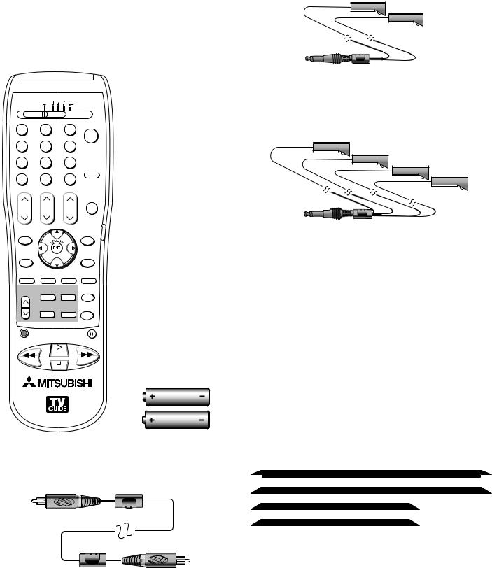
Please take a moment to review the following list of items to ensure that you have received everything.
$"#-& %#4 %57 7$3 |
%7% |
57 |
"6%*0 |
|
|
|
108&3 |
|
|
|
|
|
|
|
|
|
|
|
|
|
|
|
46# $"/$&- |
427 |
|
27 |
|
%&7*$& |
$) |
70- |
.65& |
|
1"(& |
|
|
57.&/6 |
|
|
(6*%& |
%&7*$& |
|
|
|
.&/6 |
|
|
)0.& |
7 $)*1 |
*/'0 |
"6%*0 |
7*%&0 |
1*1 $) |
1*1 101 |
&9$) |
4-&&1 |
|
1*1%&7*$& |
'03."5 $0//&$5 |
|
3&$ |
1"64& |
||
|
1-": |
|
|
3&8 3&7 |
|
|
'' '8% |
4501
AA
AA
4.One two-headed IR emitter cable (allows NetCommand to control other devices)
5.One four-headed IR emitter cable (allows NetCommand to control other devices)
6.Product registration card (not pictured)
7.Owner’s Guide (not pictured)
8.Quick Reference Guide (not pictured)
9.TV Guide On Screen® Interactive Program Guide User’s Manual (not pictured)
1. Remote Control |
2. Two AA Batteries |
Models WD-62927 and WD-73927 also include: |
10. Four-piece TV trim kit (pictured above)
3.One digital audio cable (sends the audio of digital channels to a digital audio/video receiver).
10 |
Chapter 1. Television Overview |
Special Features of Your TV
Your new high-definition widescreen television has many special features that make it the perfect center of your home entertainment system, including:
High Definition DLP™ Display System
Your widescreen Mitsubishi HDTV uses Texas Instruments most advanced Digital Light Processing™ technology for rear-projection televisions. This TV is truly a high-performance multimedia monitor uniquely capable of both stunning high-definition video images and clear, detailed, high-resolution PC images. Your TV can accept video signals from an antenna or direct cable service in standard video scanning rates of 480i, 480p, 720p, 1080i and 1080p. It is also able to accept, through the HDMI 2 connection, signals with PC resolutions from VGA (640 x 480) through XGA (1024 x 768). When used with a compatible graphics card and controlling software, this TV is also able to accept the custom PC resolution of 720p (1280 x 720). To connect a PC to HDMI 2, your PC must have a video card with DVI or HDMI output. You also need to perform NetCommand setup for the HDMI 2 PC input so that the TV knows to apply the correct PCsignal processing. All of the compatible video and PC signals will be converted to 1080p for final display; some signals will, however, result in the addition of black side bars, top and bottom bars, or both, to fill the screen, and some signals will display standard video overscan.
TV Disc Internal Digital Video Recorder (DVR)
TV Disc is an internal high-definition hard disk drive recorder, also known as a digital video recorder or DVR. In models WD-62827 and WD-73827, this disc has a capacity of 160 gigabytes and can record up to 16 hours of high-definition programming. Models WD-62927 and WD-73927 contain a 250-gigabyte disc that can record up to 25 hours of high-definition programming. TV Disc can record digital and analog programs received from CableCARD™ channels, Antenna 1, Antenna 2, devices connected to Input 1–3, or IEEE 1394 devices. This exciting feature makes possible live TV pause with instant replay. Now you can record a high-definition program and watch it later without any loss
of picture quality and without a VCR. Recordings on the TV Disc can be sent by an IEEE 1394 connection to D-VHS VCRs or to other IEEE 1394-compatible TVs and analog VCRs. When recording analog programs, TV Disc will use Dolby Digital recording technology to convert the analog stereo to high-quality digital stereo compatible with Dolby Digital decoding surround receivers. Note that a portion of the hard disc capacity is reserved for the TV Pause feature and is not available for video recording.
Dual Digital Tuners
Dual digital tuners give you a high level of flexibility when using TV Disc. For example, you can record one analog or digital channel from CableCARD™ on one antenna input (Ant-1) while viewing a different non-scrambled analog or digital channel on the other antenna input (Ant-2). You can record a non-scrambled analog or digital channel from Ant-2 while viewing an analog or digital channel from CableCARD™. Or you can view a device connected to a different input while recording a channel from CableCARD™, Ant-1, or Ant-2. Note that due to the unidirectional nature of CableCARD service, it is not possible to view one CableCARD channel and record another CableCARD channel at the same time.
Digital Cable Ready (CableCARD™)
Your widescreen Mitsubishi HDTV is “Plug-and-Play” ready. It can descramble a cable provider’s one-way digital signals with the use of a CableCARD security module. The CableCARD is used in place of a traditional cable box to access digital cable programming (including high definition). Contact your local cable provider for availability information and service details.
NetCommand® Home Network Control System
Your widescreen Mitsubishi HDTV offers a new level of networking that can seamlessly integrate selected older A/V products with new and future digital products. NetCommand supports IEEE 1394 connections, Audio Video Control system (AV/C), 5C copy protection, and IR (infrared) control of selected older products, such as VCRs, DVD players, cable boxes, and satellite receivers. NetCommand has the capability of learning remote control signals directly from many devices, allowing you to create a customized NetCommand home-theater system that works best for your viewing.
Chapter 1. Television Overview |
11 |
16:9 Widescreen Picture Format
Enjoy a full theatrical experience in the comfort of your home. View pictures as film directors intended them. Digital TV broadcasts, DVDs and newer video game consoles support this widescreen format.
Memory Card Reader
You can display a slide show of your favorite JPEG pictures or listen to MP3 or WMA audio selections that have been recorded on compatible memory cards.
TV Guide On Screen® Interactive Program Guide System
An eight-day on-screen program guide that can be used with cable, over-the-air and CableCARD™ reception. The subscription-free guide system lists regular, digital and high-definition programming. This system offers multiple sorting options to help you find the programs you want to watch and gives you easy program recording. Program listings are downloaded while your TV is turned off, so that you have current program information available every day. Note that when the system is first set up, it may take up to 24 hours to begin to receive TV program listings and then it may take up to one week to receive all eight days of TV program listings.
Multiple Options for Connecting a Home Theater Personal Computer
(Models WD-62927 and WD-73927)
In addition to the PC input available on HDMI-2, models WD-62927 and WD-73927 also have a 15-pin PC monitor input. In addition to the resolutions available via HDMI-2, This input also accepts 1920 x 1080, 60-Hz signals to provide maximum performance when used with Home Theater PC/Media Centers.
12 |
Chapter 1. Television Overview |
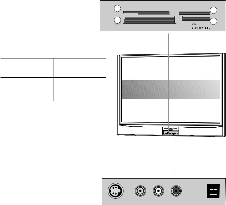
Memory Card Reader and Front-Panel Inputs
Memory Card Reader
Figure 1
The memory card reader has four card slots that accept |
|
|
|
|
|
||
a variety of popular memory card types. The reader |
|
|
|
|
|
|
|
lets you view JPEG pictures from many digital cameras |
|
|
|
|
|
||
and allows you to listen to MP3 or WMA audio |
|
|
|
|
|
|
|
files recorded from computers or other digital |
|
$"3% 4NBSU.FEJB5. |
$"3% .VMUJNFEJB $BSE5. |
||||
recording devices. |
|
1 |
|
|
|
4% $BSE |
2 |
|
|
|
|
|
|
|
|
The card slots are designed for the specific types |
3 |
|
|
|
|
|
|
of cards listed below. Other cards or objects |
$"3% $PNQBDU'MBTI¥ |
|
$"3% 1305. |
4 |
|||
should not be inserted into the slots as this may |
%*%#4 |
|
|
||||
damage the TV. See the discussion of memory |
|
.JDSP%SJWF¥ |
|
|
|
||
|
|
|
|
|
|
||
cards in chapter 6 for details about JPEG, MP3 |
Figure 1. Memory Card Reader |
|
|
|
|||
and WMA file types that are compatible with the |
|
|
|
|
|
|
|
TV. |
|
|
|
|
|
|
|
Card Compatibility |
|
|
|
|
|
|
|
CARD 1 |
CARD 2 |
|
|
|
|
|
|
SmartMedia™ |
MultiMediaCard™ |
|
|
|
|
|
|
Secure Digital (SD) |
|
|
|
|
|
|
|
|
|
|
|
|
|
|
|
CARD 3 |
CARD 4 |
|
|
|
|
|
|
CompactFlash® |
Memory Stick PRO™ |
|
|
|
|
|
|
(Types I and II) |
|
|
|
|
|
|
|
|
|
|
|
|
|
|
|
Microdrive® |
Memory Stick™ |
|
|
|
|
|
|
Input 3 and IEEE 1394 Input/Output
Figure 2
These jacks allow for convenient connection of audio/ video devices to the front of the TV.
Note that if you connect to the S-VIDEO terminal, the VIDEO terminal is deactivated. The VIDEO terminal is active only when there is no S-Video connection.
Use the IEEE 1394 input/output to connect IEEE 1394 devices, such as some camcorders. This connection works the same as the rear IEEE 1394 connections.
Please refer to the NetCommand® information in Chapter 3 for details.
Lift cover to access  card reader and front input jacks.
|
|
|
|
|
3 6)$%/ |
6)$%/ |
,, !5$)/ ) 2 |
)%%% |
|
Figure 2. Input 3 and IEEE 1394 input/output on front panel
Chapter 1. Television Overview |
13 |
Front Control Panel
The shaded buttons on the front control panel are duplicated on the remote control. The top row of labels shows the control functions when there are no TV menus displayed on the screen. The bottom row of labels shows the control functions when the TV menus are displayed on the screen or when a special function has been activated. See “Remote Control Overview” for further details on the functions of these buttons.
|
|
|
|
|
|
|
|
|
|
|
|
|
|
|
|
|
|
|
|
|
|
|
|
|
|
|
|
|
|
|
|
|
|
|
|
|
|
|
|
|
|
|
|
|
|
|
|
|
|
|
|
|
|
|
|
|
|
|
|
|
|
|
|
|
|
|
|
|
|
|
|
|
|
|
|
|
|
|
|
|
|
|
|
|
|
|
|
|
|
|
|
|
|
|
|
|
|
|
|
|
|
|
|
|
|
|
|
|
|
|
|
|
|
|
|
|
|
|
|
|
|
|
|
|
|
|
|
|
|
|
|
|
|
|
|
|
|
|
|
|
|
|
|
|
|
|
|
|
|
|
|
|
|
|
|
|
|
|
|
|
|
|
|
|
|
|
|
|
|
|
|
|
|
|
|
|
|
|
|
|
|
|
|
|
|
|
|
|
|
|
|
|
|
|
|
|
|
|
|
|
|
|
|
|
|
|
|
|
|
|
|
|
|
|
|
|
|
|
|
|
|
|
|
|
|
|
|
|
|
|
|
1 |
3 |
|
|
1 |
|
5 |
|
2 |
|
1 |
|
|
|
|||||||||||||||
Front Control Panel |
|
|
|
|
|
|
|
|
|
|
|
|
|
|
|
|
|
|
|
|
|
|
|
|
||||
1. Shaded buttons are duplicates of buttons on the remote control |
2. |
System Reset |
3. Lamp indicator |
|||||||||||||||||||||||||
4. Status indicator 5. Power/Timer indicator |
|
|
|
|
|
|
|
|
|
|
|
|
|
|
|
|
|
|
||||||||||
If the TV does not respond to either the remote control or the front panel controls and/or does not power off, press the SYSTEM RESET button with a pointed item, such as the end point of a paperclip. The TV will turn off and the TIMER light will flash quickly for about one minute. When the TIMER light stops flashing, you may again turn on the TV. The changes you made the last time the TV was on before you used the SYSTEM RESET button may be lost. Any changes that you previously saved are not lost.
A/V Reset
There may be times when you wish to reset the A/V (Audio and Video) settings back to the factory defaults. To return all the settings at once, press GUIDE and FORMAT on the front panel at the same time. To reset the defaults for individual devices, use the A/V Memory Reset selection on the Audio/Video menu.
Front-Panel Indicator Lights
 Lamp Indicator
Indicator Color |
TV Condition |
None (indicator off) |
Normal TV on or standby condition. |
Green, rapid blinking |
TV just powered off and lamp is |
|
cooling. |
Yellow, steady |
Lamp nearing end of useful life. |
Yellow, blinking |
1. Lamp access door is open or not |
|
secure. |
|
2. No lamp installed. |
Red, steady |
Lamp no longer illuminates and has |
|
reached the end of the lamp life. |
 Additional Information
Normal operation.
Begins to blink 30 seconds after turning off TV. TV can be turned on before it begins to blink or after the blinking stops, but not while the indicator is blinking. Normal operation.
This is a recommendation to have a new lamp ready before the current lamp stops illuminating. See Appendix G for ordering information.
TV will not operate until lamp access door is secure. See Appendix G for installation information.
TV will not operate without a lamp. See Appendix G for installation information.
Replace the lamp. The TV will not operate when the lamp no longer illuminates. See Appendix G for installation information.
1 |
Chapter 1. Television Overview |

Front Control Panel, continued
Status Indicator
Indicator Color |
TV Condition |
Additional Information |
|
|
|
None (indicator off) |
Normal TV on or standby condition. |
Normal operation. |
|
|
|
Yellow, steady |
Room temperature is too high. |
TV will not operate when the ambient room |
|
|
temperature is too high. Turn off the TV and wait |
|
|
until the room temperature drops. |
|
|
|
Red, either steady or |
TV may require service. |
Turn off the TV and unplug the set from the AC power |
blinking |
|
source. Wait one minute and then plug the set back |
|
|
in. |
|
|
If the LED is still on, contact your dealer or a |
|
|
Mitsubishi Authorized Service Center. See |
|
|
www.mitsubishi-tv.com or call 1-800-332-2119 to |
|
|
receive Authorized Service Center information. |
Power/Timer Indicator
Indicator Color |
TV Condition |
Additional Information |
|
|
|
|
|
None (indicator off) |
TV is powered OFF. |
Normal operation. |
|
|
|
|
|
Green, steady |
TV is powered ON. |
Normal operation. |
|
|
|
|
|
Green, rapid blinking |
1. |
TV just plugged into AC outlet. |
Wait until blinking stops before turning on |
|
|
|
(approximately 1 minute). Normal operation. |
|
2. |
AC just restored after power |
Wait until blinking stops before turning on |
|
|
failure. |
(approximately 1 minute). Normal operation. |
|
|
|
|
|
3. |
TV Rebooting after System Reset |
Wait until blinking stops before turning on |
|
|
used. |
(approximately 1-2 minutes). Normal operation. |
|
|
|
|
|
4. |
TV Rebooting after power |
Wait until blinking stops before turning on |
|
|
fluctuation or receiving abnormal |
(approximately 1 minute). Normal operation. |
|
|
digital signals from digital channel, |
|
|
|
CableCARD™, or digital device. |
|
|
|
|
|
|
5. |
You have begun the procedure |
For detailed information, see the instructions |
|
|
to update software from an |
that accompany the authorized software update. |
|
|
authorized flash memory device. |
Important: Do not use non-authorized software at |
|
|
|
any time. |
|
|
|
|
Green, slow blinking |
TV powered off and automatic-on |
Normal operation. TV can be turned on at any time. |
|
|
timer is set. |
|
|
|
|
|
|
Chapter 1. Television Overview |
15 |
Remote Control
Overview
Figure 1, next page
1.Slide Switch: Selects the A/V product to be controlled by the remote control. Select TV for NetCommand® device control.
2.Numbers: Individually select channels or enter information into menus.
3.SQV (SuperQuickView™): Scans through memorized lists of favorite channels.
4.CH(ANNEL)/PAGE: Scans up or down through memorized channels. Pages up and down through screens when used with TV Guide On Screen®, ChannelView™, a satellite receiver, some cable boxes, memory card playlists and JPEG thumbnails. Skips through DVD chapters.
5.DEVICE: Displays the Device Selection menu in which you can select the device to view (ANT-1 and ANT-2, TV Disc, or devices connected to the TV’s inputs, including IEEE 1394 devices).
6.ADJUST: Press 


 to navigate menus, change settings, and move the PIP on-screen location. Operates many NetCommand® functions. Navigate TV Guide On Screen® and change settings. Performs skip forward and backward functions during TV Pause.
7.TV MENU: Displays the 


 on-screen menu system.
8.ENTER: Selects a channel number or menu item.
9.DEVICE MENU: Displays the menu for devices connected to the TV, including CableCARD™. For VCR or DVDs, press once to display the transport menu, press again to display the VCR or DVD menu. Displays and removes options menus for TV Guide On Screen. Opens the Media Dialog Box for memory cards.
10.INFO: Press to display an on-screen summary of the current device used and any broadcast information available (including current V-Chip information). See chapter 6 for details on the on-screen display.
While in TV Guide On Screen, press repeatedly to cycle through the available info box sizes.
Press twice to display the TV Pause slider when this feature is active.
11.V-CHIP: Turns the V-Chip Lock on or off.
12.PIP/POP: Turns on PIP and cycles through PIP and POP display choices.
13.PIP CH: Scrolls up or down through memorized channels for PIP
14.PIP DEVICE: Displays PIP Selection menu to select the PIP or POP image source device
15.REC (Record): Displays the Record menu for setting up recordings to TV Disc or other recordable device. Sets up recordings while in ChannelView or the TV Guide On Screen Listings screen. Records with a VCR.
16.REW/REV: Reverse scans in TV Pause or TimeShuttle. Rewinds a VCR. Reverse scans TV Disc, DVD, A/V Disc, or memory card file.
17.POWER: Turns power on and off for the TV and other A/V products.
18.QV (QuickView™): Switches between the current channel and last channel viewed.
19.SUB/CANCEL: For digital channels, adds separator between main and sub-channel numbers. Clears SQV and some menu entries, and cancels recordings.
20.VOLUME: Changes sound level.
21.MUTE: Turns sound off or back on.
22.GUIDE: Press to display or remove TV Guide On Screen or ChannelView for ANT-1 and 2. Displays Track List for TV Disc and A/V Disc. Displays program guide for satellite receiver, or DVD Disc menu. Displays thumbnails or playlists for memory card files.
23.Light: Located on the right side of the remote control, this feature illuminates buttons or labels.
24.HOME: Exits TV on-screen menus displays; exits the TV Guide On Screen system and returns to TV viewing.
25.AUDIO: Selects individual audio settings for adjustment.
26.VIDEO: Selects individual video settings for adjustment.
27.EXCH: Exchanges PIP or POP and main TV picture.
28.SLEEP: Sets the TV to turn off within 2 hours. See the next page for setup instructions.
29CONNECT: Initiates IEEE 1394 peer-to-peer connections.
30.FORMAT: Changes the shape and size of the main TV picture.
31.PAUSE: With TV Pause enabled (with the Always or On Request option), pauses program viewing and
activates TV Pause to allow forward/backward scans in a broadcast program (when no PIP/POP image is displayed). Returns to TV viewing from TV Pause. With TV Pause disabled (Off), operates as standard pause by freezing a broadcast TV picture (when no PIP/POP image is displayed). When PIP/POP is displayed, freezes that image. Pauses TV Disc, a VCR, DVD, A/V Disc, or memory card file playback.
32.PLAY: Plays the TV Disc, a VCR, DVD, A/V Disc, or memory card file.
33.FF/FWD: Forward scans in TV Pause. Fast forwards a VCR. Forward scans TV Disc, DVD, A/V Disc, or memory card file.
34.STOP: Stops play of the TV Disc, a VCR, DVD, A/V Disc, or memory card file.
16 |
Chapter 1. Television Overview |

Remote Control, continued
1 |
$"#-& %#4 %57 |
7$3 %7% |
|
17 |
||
|
|
|||||
|
|
|
||||
|
|
57 |
"6%*0 |
|
||
2 |
|
|
|
|
18 |
|
|
|
|
|
|
||
|
108&3 |
|
||||
|
|
|
|
19 |
||
3 |
|
|
|
|
||
|
|
|||||
4 |
|
|
|
46# $"/$&- |
20 |
|
|
|
|
|
|||
5 |
427 |
|
27 |
|
21 |
|
|
|
|
|
|||
6 |
%&7*$& |
$) |
70- |
.65& |
22 |
|
7 |
|
|
|
|
||
|
1"(& |
|
|
23 |
||
|
|
|
|
|||
|
57.&/6 |
|
|
(6*%& |
||
8 |
%&7*$& |
|
|
|
24 |
|
9 |
|
|
|
25 |
||
.&/6 |
|
|
)0.& |
|||
|
|
|
|
|||
10 |
7 $)*1 |
*/'0 |
"6%*0 |
7*%&0 |
26 |
|
11 |
1*1 $) |
1*1 101 &9$) |
4-&&1 |
27 |
||
12 |
||||||
|
|
|
|
28 |
||
|
|
1*1%&7*$& '03."5 $0//&$5 |
||||
13 |
|
|
||||
|
|
|
|
29 |
||
|
|
|
|
|
||
14 |
3&$ |
1"64& |
30 |
|||
|
|
|
|
|
31 |
|
15 |
|
|
1-": |
|
32 |
|
3&8 3&7 |
|
'' '8% |
||||
|
|
|
4501 |
|
|
|
|
|
|
|
|
33 |
|
16 |
|
|
|
|
34 |
|
|
|
|
|
|
||
Figure 1. Remote Control Overview
Battery Installation
Figure 2
Installing the Batteries:
1.Remove the remote control’s back cover by gently pressing the ribbed tab in the direction of the arrow and sliding off the cover.
2.Load the batteries, making sure the polarities (+) and (-) are correct. For best results, insert the negative (-) side first.
"" BMLBMJOF CBUUFSJFT
Figure 2. Operation: Installing the Batteries
Care
For Best Results from the Remote Control:
•Be within 20 feet of the equipment.
•Do not press two or more buttons at the same time unless instructed.
•Do not allow unit to get wet or become heated.
•Avoid dropping on hard surfaces.
•Do not use harsh chemicals to clean. Use only a soft, lightly moistened cloth.
•Do not mix new and old batteries.
•Do not heat, take apart, or throw batteries into fire.
•Use only AA alkaline batteries.
Hint: If the remote is in the TV layer and does not function, press POWER and 935 to reset the remote.
Sleep Timer
Setting the Sleep Timer:
1.Press SLEEP on the remote control.
2.Each additional press of SLEEP increases the time displayed by 30 minutes up until the maximum value of 120 minutes.
3.After five seconds of inactivity, the message will disappear.
4.Press SLEEP to view the time remaining before the timer turns the TV off.
Cancelling the Sleep Timer:
1.Press SLEEP to display the on-screen message.
2.Press SLEEP repeatedly until OFF is displayed.
Note: After five seconds of inactivity, the message box disappears.
Chapter 1. Television Overview |
17 |
TV Back Panel
3
Note: 15-pin D-subminiature PC input (item 6) offered on models WD-62927 and WD-73927 only.
5
6
 7
7
 2
2
8

 9
9 


 1
1


%57 $"#-& 7)' 6)'
12
 11
11


|
|
10 |
*&&& |
||
|
|
|
|
*/165 |
|
|
|
|
|
|
065165 |
|
|
|
|
|
|
|
|
|
|
|
|
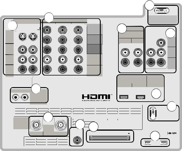
1. Antenna (ANT-1 MAIN, ANT-2 AUX)
ANT-1 MAIN and ANT-2 AUX can each receive both digital and analog over-the-air channels from a VHF/UHF antenna or non-scrambled digital/analog cable source.
Your primary viewing signal source should be connected to ANT-1 MAIN. ANT-1 MAIN must be used to view premium subscription cable TV service authorized by the CableCARD™ access card. The CableCARD access card is provided by your local cable company. ANT-2 AUX can continue to receive over-the-air or non-scrambled cable signals.
2. IR EMITTER NetCommand®
IR Emitters connected to these jacks are used by the NetCommand system of the TV to control external analog devices such as cable boxes, VCRs, DVDs, satellite receivers and audio receivers. This system is also coordinated with the TV Guide On Screen® system for the control of cable boxes and to activate the record feature of
your VCR. Either connection can be used for NetCommand functions.
3. INPUT 1 and 2
(Audio/Video 1 and 2)
Inputs 1 and 2 can be used for the connection of a VCR, Super VHS (S-VHS) VCR, DVD player, standard satellite receiver or other A/V device to the TV. Please note that if S-VIDEO and VIDEO are available for the input, you must choose to connect only one. They cannot both be connected at the same time.
. COMPONENT 1–3 Inputs
YPbPr ( 80i/ 80p/720p/1080i)
These inputs can be used for the connection of devices with component video outputs, such as a DVD player, external HDTV receiver, or compatible video game system. Please see Appendix A for signal compatibility.
18 |
Chapter 1. Television Overview |
TV Back Panel, continued
5. DVI Analog Audio
Unlike HDMI, DVI does not carry audio information on the same cable. Use these analog stereo audio inputs when using the HDMI input with a device that outputs DVI instead of HDMI, such as DVI output from a DVD player.
6. PC Input (models WD-62927, WD-73927 only)
(VGA/W-VGA/SVGA/W-SVGA/XGA/W-XGA/1280 x 720, 1920 x 1080, 60 Hz)
This input can be used to connect a personal computer. Please see Appendix A for signal compatibility. For audio, use DVI Analog Audio 2 input.
7. AUDIO OUTPUT, RECORD OUTPUT
AUDIO OUTPUT sends analog audio of the program currently shown on the screen to an A/V surround sound receiver or stereo system. Digital audio from digital channels, FireWire® (DTVLink/IEEE 1394) devices and HDMI devices is converted to analog audio by the TV. If you do not have a digital A/V receiver, this should be the only audio connection between the TV and your analog A/V receiver or stereo system.
RECORD OUTPUT sends analog audio and video to a VCR for recording purposes. The program on this output can be either the one you are currently watching or a different one. Signals from digital channels and FireWire (IEEE 1394) devices are converted to analog signals. There is no video signal when copy restrictions are in effect. Component, HDMI, and PC inputs are not available for recording.
8. HDMI™ 1 and 2
The HDMI (High Definition Multimedia Interface) supports uncompressed standard and high-definition digital video formats and PCM digital audio format.
Use these inputs to connect to EIA/CEA-861 compliant devices such as a high-definition receiver or DVD player. These inputs support 480i, 480p, 720p and 1080i video formats.
These inputs can also be used as a DVI connection with separate analog audio inputs. An optional HDMI-to-DVI adaptor or cable is necessary to make this connection and may be available from your local electronics retailer. When using the optional HDMI-to-DVI adapter, the DVI analog audio inputs on your TV allow you to receive left and right stereo audio from your DVI device.
This input is HDCP (High-Bandwidth Digital Copy Protection) compliant.
HDMI 2
HDMI 2 also allows the TV to display DVI or HDMI output from a PC. To view PC video on the TV, you must activate the PC option in NetCommand. You can do this during
initial NetCommand setup by selecting the PC option in the Device Setup screen. To do this at any time afterwards, use the NetCommand Add function.
To listen to audio from a PC when using PC DVI output, you must connect the PC audio output to the TV’s DVI Analog Audio 2, located above the HDMI 2 input.
9. MonitorLink/RS-232C Control
When used as a MonitorLink port with a Mitsubishi receiver/controller, provides enhanced functions such as automatic power on/off and input-port selection.
When used as an RS-232C connection, provides a port for an external controller that uses RS 232C signals for
communication. For RS 232C-compatible signal protocols, please visit www.mitsubishi-tv.com.
10. DTVLink™/IEEE 1394
These jacks allow the TV to connect to external IEEE 1394 digital products by means of a single cable. Two jacks are provided for this purpose, which allow for a high degree of flexibility for connecting your NetCommand-controlled system. Detailed information regarding IEEE 1394 connection requirements is in Chapter 2, “Connecting.”
11. CableCARD™ Slot
The CableCARD access card from your cable TV service provider is inserted into this slot. The top of the card should face in the direction indicated by CARD TOP  .
.
CableCARD is a nationwide standard system that allows your local cable TV provider to supply you with an access card customized to your account. This card allows the TV to receive, decode and unscramble the premium digital channels included in your cable TV subscription without the use of a cable box. See page 84 for additional CableCARD information and activation instructions.
If your cable company is not currently offering CableCARD access cards, you will need to use a cable box provided and authorized by your local cable company to view scrambled channels.
12. Digital Audio Output
This output sends Dolby® Digital or PCM digital audio to your digital A/V surround sound receiver. Analog audio from analog channels and devices is converted by the TV to PCM digital audio. If you have a digital A/V receiver, in most cases this should be the only audio connection between the TV and your A/V receiver. If you have MP3 audio sources, however, you need to connect the TV’s
analog AUDIO OUTPUT (left and right) to your A/V receiver.
Chapter 1. Television Overview |
19 |
Additional Information
System Reset Button
If the TV doesn’t respond to either the remote control or the front panel controls or will not power off, press the SYSTEM RESET button on the front panel with a pointed item such as the point of a ball point pen or end tip of a paperclip.
The TV will turn off and the green LED will flash quickly for about one minute. When the green LED stops flashing, you may turn on the TV again. The changes you made while the TV was most recently on, before you used the SYSTEM RESET button, may be lost; the changes you made previously, however, are not lost. Only those changes since the last power on may be lost when the system reset button is pressed. All other settings are retained.
Demo Track
The TV Disc in some TVs comes a with a demo track that plays in a continuous loop. To delete the demo track:
1.Select the TV Disc as the viewing source.
2.Press GUIDE to display the Track List.
3.Highlight the track name “demo track” and press CANCEL.
4.Press CANCEL again to confirm the deletion.
Using the Reset Menu for Reset of the TV or TV Disc
Select any device from the Device Selection menu, except for TV Disc. Press TV MENU followed by 1,2,3 to see the RESET SERVICE MENU to reset the TV or TV Disc.
Read on-screen warnings before proceeding, as some user data or settings may be erased.
Your choices are:
Reset System Defaults (CAUTION: All settings, except V-Chip, will be reset to the original factory defaults).
Reset TV Disc (Track List will not be affected).
Erase TV Disc (CAUTION: Track List will be cleared).
Reformat TV Disc (CAUTION: Track List will be cleared).
IMPORTANT
Do not attempt to update the software of this TV with software or cards that are not provided by or authorized by Mitsubishi Digital Electronics America, Inc. Non-authorized software may damage the TV and will not be covered by the warranty.
IMPORTANT
Portions of the advanced circuitry of this TV must continue to operate even when the TV is turned off. Some of these circuits therefore need to be cooled at all times. A low-power standby fan may be heard in a quiet environment. This is normal operation.
20 |
Chapter 1. Television Overview |
Chapter 2
Connecting
External Devices and NetCommand® Setup. . . . . . . . . . . . . . . . . 22 Wall Outlet Cable. . . . . . . . . . . . . . . . . . . . . . . . . . . . . . . . . . . . 23 Standard Cable Box. . . . . . . . . . . . . . . . . . . . . . . . . . . . . . . . . . 23 Antenna with a Single Lead. . . . . . . . . . . . . . . . . . . . . . . . . . . . . 24 Antennas with Separate UHF and VHF Leads. . . . . . . . . . . . . . . . 24 VCR to an Antenna or Wall Outlet Cable (Audio & Video).. . . . . . . . 25 VCR to a Cable Box (Audio & Video). . . . . . . . . . . . . . . . . . . . . . . 26 A/V Receiver (Stereo System). . . . . . . . . . . . . . . . . . . . . . . . . . . 27 Satellite Receiver or Other Device with S-Video.. . . . . . . . . . . . . . 27 DVD Player with Component Video.. . . . . . . . . . . . . . . . . . . . . . . 28 DVI Device.. . . . . . . . . . . . . . . . . . . . . . . . . . . . . . . . . . . . . . . . 28 HDTV Cable Box or Satellite Receiver with Component Video. . . . . 29 HDMI Device. . . . . . . . . . . . . . . . . . . . . . . . . . . . . . . . . . . . . . . 29 MonitorLink Control/RS-232C Device.. . . . . . . . . . . . . . . . . . . . . 30 IR Emitter NetCommand®.. . . . . . . . . . . . . . . . . . . . . . . . . . . . . 31 Compatible IEEE 1394 Devices.. . . . . . . . . . . . . . . . . . . . . . . . . . 33 Helpful Hints for NetCommand Connections.. . . . . . . . . . . . . . . . 34
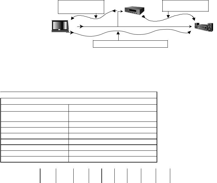
Connecting External Devices and NetCommand® Setup
NetCommand is able to control many current audio and video devices by sending remote control signals from the TV to each device through IR emitters. Additionally, it is also able to learn the remote control signals used by most audio video devices not already in the TV’s memory. NetCommand can automatically switch the TV and compatible or learned Audio/Video (A/V) Receivers to the correct input used with each device. It is important that the inputs on the TV and A/V receiver back panels match the NetCommand setup that is displayed on screen.
To simplify the installation of NetCommand, there is a step-by-step on-screen NetCommand Setup procedure in this chapter, which details the type and brands of devices you are connecting to the TV. The NetCommand Setup also
assigns preset TV and |
|
Device to be |
|
|
A/V receiver inputs for |
|
|
||
video and stereo |
connected |
stereo and/or digital |
||
each device. You should |
||||
|
||||
connect each device to |
audio cables |
|
audio cables |
|
the TV input (both audio |
|
|
|
|
and video) and to the A/V |
|
|
|
|
receiver (audio) as shown |
|
*3 &NJUUFST |
|
|
in the figure below. If you |
|
|
||
|
|
|
||
connect devices to inputs |
TV |
|
AV |
|
other than the ones shown |
|
Receiver |
||
as presets, you must |
|
|
||
stereo and/or digital audio cables |
||||
change the NetCommand |
|
|
|
|
setup accordingly. See the |
|
|
|
|
Edit NetCommand information starting on page 43.
The following charts show which preset inputs you should use on the TV and A/V receiver. Chart 1 shows the default TV inputs existing in NetCommand.
Chart 2 shows the A/V receiver inputs used by A/V receiver models already known by NetCommand.
 Chart 1
NetCommand Default Device Audio and Video Outputs to TV Inputs
Cable for CableCARD™ Service |
ANT-1 |
|
|
|
|
|
|
|
|
|
|
|||||
Antenna/Cable (digital/analog) |
|
ANT-1 if primary viewing source, |
|
|
|
|
|
|
||||||||
|
|
|
|
|
ANT-2 if secondary viewing source |
|
|
|
|
|
||||||
Cable box |
|
|
|
|
COMPONENT-1 |
|
|
|
|
|
|
|
|
|
||
VCR |
|
|
|
|
Input-1 |
|
|
|
|
|
|
|
|
|
|
|
Satellite Receiver (SAT) |
|
Input-2 |
|
|
|
|
|
|
|
|
|
|
||||
Camcorder |
|
|
|
|
Input-3 (on front panel) |
|
|
|
|
|
|
|
|
|||
DVD Player |
|
|
|
|
COMPONENT-2 |
|
|
|
|
|
|
|
|
|
||
PC (models WD-62827, WD-73827) |
HDMI-2 |
|
|
|
|
|
|
|
|
|
|
|||||
PC (models WD-62927, WD-73927) |
PC INPUT |
|
|
|
|
|
|
|
|
|
|
|||||
|
|
|
|
|
|
|
|
|
|
|
|
|
|
|||
$IBSU |
.JUTVCJTIJ |
.JUTVCJTIJ #PTF %FOPO *OUFHSB |
,FOXPPE |
.BSBOU[ 1JPOFFS 1JPOFFS 3PUFM 4POZ |
:BNBIB |
:BNBIB |
||||||||||
.PEFM |
.PEFM |
.PEFM |
|
.PEFM |
.PEFM |
.PEFM |
.PEFM |
.PEFM |
.PEFM |
.PEFM |
.PEFM |
.PEFM |
.PEFM |
|||
|
|
|||||||||||||||
|
. 73 |
. 73 |
|
-JGFTUZMF ¥ "73 |
%53 |
73 |
43 |
|
749 % |
749 59 |
349 |
453 %& |
39 7 |
39 7 |
||
|
. 73 |
. 73 |
|
|
|
|
|
|
|
|
|
|
|
|
|
|
%FWJDF "VEJP 0VUQVU UP |
"7 3FDFJWFS *OQVUT CZ /BNF |
|
|
|
|
|
|
|
|
|
|
|||||
7$3 |
7$3 |
7$3 |
|
7$3 |
|
7$3 |
7JEFP |
7JEFP |
7$3 |
|
7$3 5BQF |
7$3 %73 |
7JEFP |
7JEFP |
7$3 |
7$3 |
4BUFMMJUF 3FDFJWFS |
"VY |
$BCMF %#4 |
|
"69 |
|
$% |
7JEFP |
7JEFP |
%44 |
|
$% |
4"5 |
7JEFP |
57 %#4 |
57 %#4 |
% 57 -% |
%7% 1MBZFS |
%7% |
%7% |
|
CVJMU JO |
|
%7%7%1 |
%7% |
7JEFP |
%7% |
|
-% 4"5 |
%7% -% |
7JEFP |
5"1& .% |
$% |
%7% |
57 .POJUPS 0VUQVU |
57 |
57 |
|
57 |
|
57 %#4 |
7JEFP |
7JEFP |
57 |
|
%7% 57 |
57 |
7JEFP |
%7% -% |
%7% -% |
$#- 4"5 |
%JHJUBM "VEJP |
|
|
|
|
|
|
|
|
|
|
|
|
|
|
|
|
After using NetCommand Setup, you may go to the NetCommand menu at any time to change the inputs you used for connecting each device, custom name devices, add devices not included in the presets above or delete devices no longer used. See Edit NetCommand. See Helpful Hints at the end of this chapter for additional information on device setup.
22 |
Chapter 2. Connecting |
Connecting a Wall Outlet Cable or Cable Box
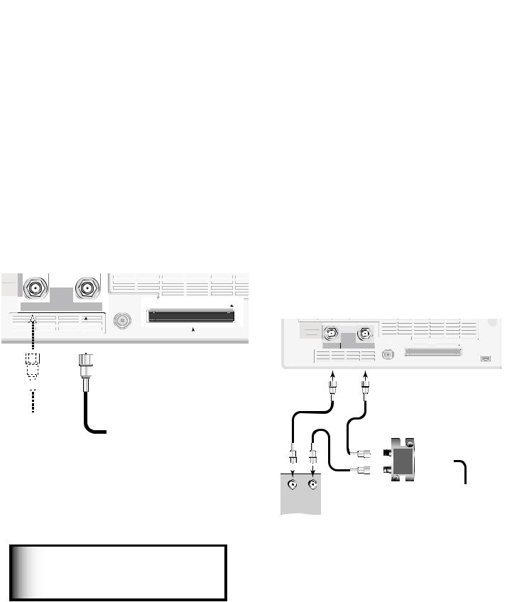
Wall Outlet Cable
(can be used with a CableCARD™)
Figure 1
It is very important to connect the incoming cable for your primary viewing source to ANT-1, especially for CableCARD™ use and to download TV Guide On Screen® listings.
1.Connect the primary incoming coaxial lead cable to ANT 1/MAIN on the TV back panel.
2.For an optional secondary antenna source, connect an antenna (or cable) to ANT 2/AUX.
3.If you have subscribed to a CableCARD™ service, the CableCARD can now be inserted into the CableCARD SLOT. Using a Phillips screwdriver, remove the CableCARD cover screws. Insert the CableCARD, then replace the cover and screws. The top of the card should face in the direction the CARD TOP arrow indicates.
Additional CableCARD information is on page 84. Detailed TV Guide On Screen information is in the separate User’s Manual.
Standard Cable Box
(cable box, other than an HDTV cable box; this setup allows two-channel PIP)
Figure 2
3 coaxial cables and one two-way RF splitter are required. These are not included with the TV.
Note: See page 29 to connect an HDTV cable box.
1.Connect the incoming cable to IN on an RF splitter.
2.Connect one coaxial cable from OUT on the RF splitter to ANT-1 MAIN on the TV back panel.
3.Connect one coaxial cable from OUT on the RF splitter to IN on the standard cable box.
4.Connect one coaxial cable from OUT on the cable box to ANT-2 AUX on the TV back panel.
5.After the cable box is connected to ANT-2 AUX as shown, use the NetCommand menu Change option to change the default connection for the cable box, go to the RF Connection for Cable screen and do the following:
a.Check the RF check box.
b.For antenna, select ANT-2.
c.For Channel, select the channel to which the TV must be tuned for your cable box. The default channel is 3.
When this setup is complete, you can use the TV remote control to change channels on the cable box.
Figure 1. Wall Outlet Cable
IMPORTANT
Additional connection cables are not provided with the TV. They are available at most electronics stores.
Figure 2. Connecting a Cable Box
Note: To use a cable box connected to ANT-2 as shown above, you must make the noted NetCommand changes. The changes are required to change the NetCommand cable-box default connection (Component-1) to the actual connection (ANT-2).
Chapter 2. Connecting |
23 |
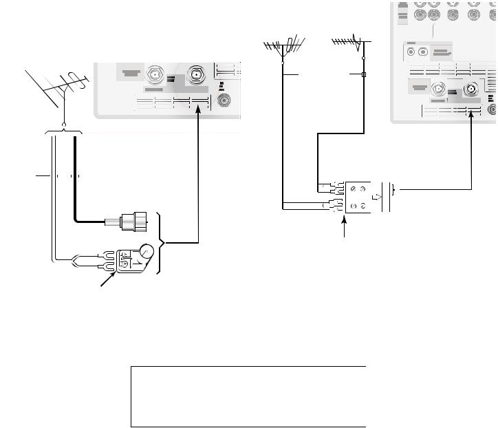
Connecting an Antenna with a Single Lead or Antennas with Separate UHF and VHF Leads
Antenna with a Single Lead
(not for use with CableCARD™)
Figure 3
For antennas with flat twin leads
A 300-ohm-to-75-ohm transformer is required. This is not included with the TV, but is available at most electronics stores.
1.For an antenna with flat twin leads, connect the 300-ohm twin leads to the 300-ohm-to-75-ohm transformer.
2.Push the 75-ohm side of the transformer onto ANT-1 MAIN on the TV back panel.
For cable or antenna with coaxial lead
Connect the coaxial lead directly to ANT-1 MAIN on the TV back panel.
Antennas with Separate UHF and VHF Leads
Figure 4
A UHF/VHF combiner is required. This is not included with the TV, but is available at most electronics stores.
1.Connect the UHF and VHF antenna leads to the UHF/ VHF combiner.
2.Push the combiner onto ANT-1 MAIN on the TV back panel.
Figure 4. Connecting separate UHF and VHF Antennas
Figure 3. Connecting a Single Antenna
2 |
Chapter 2. Connecting |

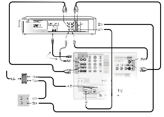
Connecting a VCR to an Antenna or Wall Outlet Cable Connecting VCR Audio and Video to the TV
VCR to an Antenna or Wall Outlet Cable (Audio & Video)
Figure 5
A two-way RF splitter, 3 coaxial cables, right and left audio cables, and an S-video or video cable are required. These are not included with the TV but are available at most electronics stores.
1.Connect the incoming cable or Antenna to IN on the RF splitter.
2.Connect one coaxial cable from OUT on the RF splitter to ANTENNA IN on the VCR back panel.
3.Connect one coaxial cable from OUT on the RF splitter to ANT-1 MAIN on the TV back panel. This connection also allows you to use the TV Guide On Screen® feature.
4.To use the TV speakers with the VCR, connect a set of audio cables from AUDIO OUT on the VCR back panel to INPUT-1 AUDIO-LEFT (MONO) and AUDIORIGHT on the TV back panel. The red cable connects to the R (right) channel and the white cable connects to the L (left) channel. If your VCR is mono (nonstereo), connect only the white (left) cable.
5.Connect either an S-Video or Video cable from VIDEO OUT on the VCR back panel to INPUT-1 VIDEO on the TV back panel. Only one type of video cable should be connected. S-Video is recommended, if available.
6.For NetCommand®-controlled recordings (including TV Guide On Screen), connect a set of audio cables from AUDIO IN on the VCR back panel to RECORD OUTPUT/AUDIO-LEFT and AUDIO-RIGHT on the TV back panel. The red cable connects to the R (right) channel and the white cable connects to the L (left) channel.
7.Complete the NetCommand controlled recordings connections by connecting a Video cable from VIDEO IN on the VCR back panel to RECORD OUTPUT/VIDEO on the TV back panel.
Note:
NetCommand® will assume your VCR is connected to inputs as shown on this page. If you use any other inputs for your VCR or add a second VCR, this change must match in the NetCommand system. See Edit NetCommand... in Chapter 3 for more information.
Figure 5. Connecting a VCR to an Antenna or Wall Outlet Cable
Chapter 2. Connecting |
25 |
Connecting a VCR to a Cable Box (Audio & Video)
VCR to a Cable Box (Audio & Video)
Figure 6
A two-way RF splitter, 4 coaxial cables, right and left audio cables and an S-Video or Video cable are required. These are not included with the TV but are available at most electronics stores.
1.Connect the incoming cable to IN on the RF splitter.
2.Connect one coaxial cable from OUT on the RF splitter to ANTENNA IN on the cable box back panel.
3.Connect one coaxial cable from OUT on the RF splitter to ANT-1 MAIN on the TV back panel. This connection also allows you to use the TV Guide On Screen® feature.
4.Connect one coaxial cable from OUT on the cable box to ANTENNA IN on the VCR back panel.
5.Connect one coaxial cable from ANTENNA OUT on the VCR back panel to ANT-2 AUX on the TV back panel (optional).
6.To use the TV speakers with the VCR, connect a set of audio cables from AUDIO OUT on the VCR back panel to INPUT-1 AUDIO-LEFT (MONO) and AUDIO-RIGHT on the TV back panel. The red cable
connects to the R (right) channel and the white cable
connects to the L (left) channel. If your VCR is mono (non-stereo), connect only the white (left) cable.
7.Connect either an S-Video or composite video cable from VIDEO OUT on the VCR back panel to INPUT 1 VIDEO on the TV back panel. Connect only one type of video cable. S-Video is recommended, if available.
8.For NetCommand®-controlled recordings (including TV Guide On Screen)
a.Connect a set of audio cables from AUDIO IN on the VCR back panel to RECORD OUTPUT/AUDIOLEFT (MONO) and AUDIO-RIGHT on the TV back panel. The red cable connects to the R (right) channel and the white cable connects to the L (left) channel.
b.Connect a video cable from VIDEO IN on the VCR back panel to RECORD OUTPUT/VIDEO on the
TV back panel.
Note: With this connection configuration, it is possible to view live cable programs through the VCR. For best picture quality, however, always view live cable programs directly from the cable box instead of the VCR.
Note: NetCommand® will assume your
VCR is connected to inputs as shown on this page. If you use any other inputs for your VCR or add a second VCR, this change must match in the NetCommand system. See Edit NetCommand... in Chapter 3 for more information.
Figure 6. Connecting a VCR to a Cable Box
26 |
Chapter 2. Connecting |
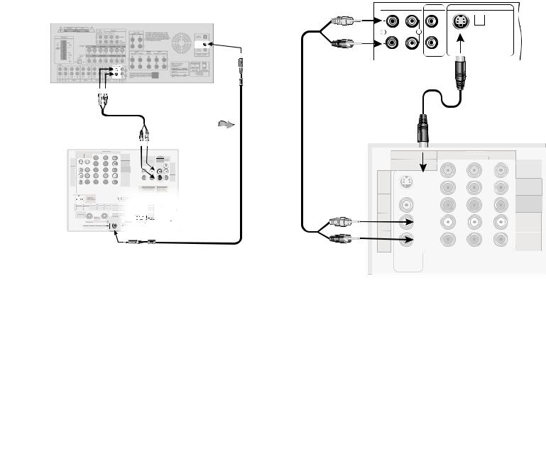
Connecting an A/V Receiver (Stereo System)
Connecting a Satellite Receiver or Other Device with S -Video
A/V Receiver (Stereo System)
Figure 7
Most setups require either a digital audio cable or stereo audio cables. In some circumstances, you may need to connect both digital audio and stereo audio. A digital audio cable is provided with the TV. Stereo audio cables are not included.
•To connect an analog A/V receiver:
Connect a set of stereo audio cables from AUDIO OUTPUT on the TV back panel to the TV AUDIO INPUT on the back of the A/V receiver. The red cable connects to the R (right) channel and the white cable connects to the L (left) channel.
•To connect a digital A/V receiver with Dolby® Digital surround sound:
Connect one end of the digital audio cable supplied with the TV to DIGITAL AUDIO on the back of the TV. Connect the other end to the COAXIAL DIGITAL INPUT on the back of the A/V receiver.
Figure 7. Connecting an A/V receiver
On rare occasions, an HDMI signal may be copyrestricted and cannot be output from the TV as a digital signal. To hear these copy-protected signals through the A/V receiver, use connections for analog A/V receivers.
MP3 audio from memory cards cannot be connected to digital audio. To listen to MP3 playback from the TV memory card player through your A/V receiver, use the connections for an analog A/V receiver
Check the A/V receiver’s Owner’s Guide for information concerning use of the digital input and switching between digital sound and analog stereo sound from the TV.
Satellite Receiver or Other Device with S-Video
Figure 8
An S-Video cable and audio cables are required. These are not included with the TV.
1.Connect an S-Video cable from VIDEO OUT on the satellite receiver back panel to INPUT-2 S-VIDEO on the TV back panel.
2.Connect a set of audio cables from AUDIO OUT on the satellite receiver back panel to INPUT-2 AUDIO on the TV back panel. The red cable connects to the R (right) channel and the white cable connects to the L (left) channel.
Note: Refer to the Satellite Receiver Owner’s Guide for Dish Antenna connections
Figure 8. Connecting a Satellite Receiver with S-Video
Note: NetCommand® assumes you connected your satellite receiver to Input-2. If you add a second satellite receiver or use any other inputs for your satellite receiver, this change must match in the NetCommand system. See Editing NetCommand Setup in Chapter 3 for more information.
Chapter 2. Connecting |
27 |
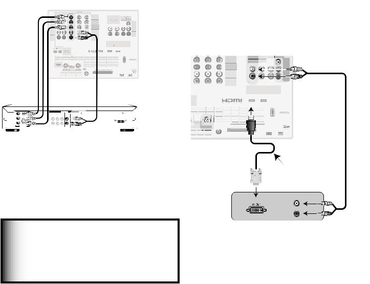
Connecting a DVD Player with Component Video Connecting a DVI Device
DVD Player with Component Video
Figure 9
Component video cables and audio cables are required. These are not included with the TV.
1.Connect the Component Video cables from Y/Pr/ Pb VIDEO OUT on the back of the DVD player to COMPONENT-2 on the TV back panel, matching the correct connection:
•Y to Y (Green)
•Pr to Pr (Red)
•Pb to Pb (Blue)
2.Connect a set of audio cables from AUDIO OUT
on the back of the DVD player to COMPONENT-2 AUDIO Input on the TV back panel. The red cable connects to the R (right) channel, and the white cable connects to the L (left) channel.
Figure 9. Connecting a DVD Player with Component Video
Note: NetCommand® assumes you connected your DVD player to Component-2. If you add a second DVD or use any other inputs for your DVD, this change must be reflected in the NetCommand system. See Edit NetCommand... in Chapter 3 for more information.
DVI Device
Figure 10
A DVI-to-HDMI cable or DVI/HDMI adaptor and HDMI cable and audio cables are required. These are not included with the TV. They may be available at your local electronics retailer.
1.Connect the DVI-to-HDMI cable (recommended) or HDMI cable with DVI/HDMI adaptor from the DVI device’s back panel to the TV back panel.
NOTE: If you are using a DVI/HDMI adaptor, it is important to connect the adaptor to the DVI device for best performance.
2.Connect a set of audio cables from AUDIO OUT on the DVI device back panel to the INPUT/DVI Analog Audio on the TV back panel. The red cable connects to the R (right) channel, and the white cable connects to the L (left) channel.
NOTE: The HDMI connection supports copy protection (HDCP). Some devices require connecting to an analog input first, in order to view on-screen menus and select DVI as the ouput. Please review your equipment instructions for DVI connectivity and compatibility.
Figure 10. Connecting a DVI Device
28 |
Chapter 2. Connecting |
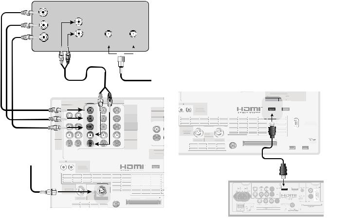
Connecting an HDTV Cable Box or Satellite Receiver with Component Video
Connecting an HDMI Device
HDTV Cable Box or Satellite Receiver with Component Video
Figure 11
A coaxial splitter, RCA component video cables, and audio cables are required. These are not included with the TV.
1.Connect the outside antenna, cable, or satellite to ANT or SATELLITE IN on the cable box or satellite receiver. See your device’s owner’s guide for instructions and cable compatibility.
2.Connect the incoming terrestrial antenna or cable (not satellite) to ANT-1 on the TV back panel (a coaxial splitter, available at most electronic supply stores, may be required to complete this installation). This connection is used by TV Guide On Screen® to download program listings.
)%57 3FDFJWFS XJUI : 1S 1C $POOFDUJPOT
: |
"6%*0 |
1C |
- |
|
|
1S |
3 |
|
*/ '30. "/5 4"5&--*5& */
*ODPNJOH "OUFOOB PS $BCMF
8IJUF |
|
3FE |
|
PS |
||
|
|
|||||
|
|
|
|
5P BOUFOOB |
||
|
|
|
|
|
DBCMF PS |
|
|
|
|
|
|
||
|
|
|
|
|
|
TBUFMMJUF |
|
|
|
|
|
|
|
|
|
8IJUF |
|
3FE |
||
4 7*%&0
7*%&0
"6%*0 -&'5
.0/0
"6%*0
3*()5
|
$0.10/&/5 |
|
*/165 |
:1C1S J Q Q J |
|
|
2 |
 57 #BDL 1BOFM
:
1C
1S
"6%*0 -&'5
.0/0
"6%*0
3*()5
*/16
%7* "OBMPH "
.0/*503-*/ 7*%&0 J "6%*0 1$.
( -JOL
*3 &.*55&3 /FU $PNNBOE
%57 $"#-& 7)' 6)'
64& 8*5) $BCMF$"3
|
*(*5"- |
|
"/5 "69 |
"6%*0 |
$BCMF$"3% 64& 8*5) "/5 $"3% 501 |
65165 |
Figure 11. Connecting an External HDTV Receiver with Component Video Connections
3.Connect RCA-type cables from the YPrPb outputs on the HDTV receiver to Component-1 on the TV back panel, matching the correct connections:
HDTV Receiver to TV Back panel
•Y to Y
•Pr to Pr
•Pb to Pb
4.Connect L (left) and R (right) audio cables from the DTV receiver to Component-1 AUDIO on the TV back panel.
5.If you are using a satellite receiver, you must change the input through NetCommand. Open the NetCommand Connection for [Device] screen (see page 48) to make the change.
Note: To receive the benefits of a digital A/V receiver, connect your cable box or satellite receiver’s digital audio out to a digital input on your digital A/V receiver.
HDMI Device
Figure 12
An HDMI-to-HDMI cable is required. This is not included with the TV. It may be available at your local electronics retailer
Connect an HDMI cable from the TV back panel to the HDMI device output. HDMI devices provide video and audio through this cable, so no other connection is required. You can connect two HDMI devices to the TV back panel through the HDMI connections.
Figure 12. Connecting an HDMI Device
Note: To use the benefits of digital surround sound from the HDMI device, connect the digital audio output of the HDMI device directly to the A/V receiver.
Chapter 2. Connecting |
29 |
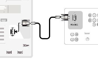
Connecting a MonitorLink™ Control/RS-232C Device
MonitorLink Control/RS-232C Device
Figure 13
A 9-pin RS-232C cable is required. This is not included with the TV. It may be available at your local electronics retailer
When used as an RS-232C port, you can connect to other external controllers. See mitsubish-tv.com for RS232C command protocols. Connect a 9-pin RS-232C cable from the TV back panel to the MonitorLink or RS232C jack on the external control device.
When used for MonitorLink Control, you can connect to a Mitsubishi HD Receiver/Controller, such as the HD-5000 or HD-6000. When connected in this way, it provides coordinated power on/off between the TV and the receiver/controller.
|
|
|
|
|
|
|
|
34 $ %FWJDF |
)%.* |
|
|
1$ '03 )%.* |
|
|
|
||
Q J |
|
0/-: )[ |
|
|
|
57 |
||
*/&"3 |
|
|
7(" 8 7(" |
|
|
|
||
|
|
|
47(" 8 47(" |
|
|
|||
|
|
|
9(" 9 |
|
|
|
|
|
*&&&
*/165
065165
Figure 13. RS-232C connection
30 |
Chapter 2. Connecting |
 Loading...