


 Loading...
General-Purpose AC Servo
 J2-Super Series
General-Purpose Interface
MR-J2S-
 A
A
Servo Amplifier
Instruction Manual
B

 Safety Instructions
(Always read these instructions before using the equipment.)
Do not attempt to install, operate, maintain or inspect the servo amplifier and servo motor until you have read through this Instruction Manual, Installation guide, Servo motor Instruction Manual and appended documents carefully and can use the equipment correctly. Do not use the servo amplifier and servo motor until you have a full knowledge of the equipment, safety information and instructions.
In this Instruction Manual, the safety instruction levels are classified into "WARNING" and "CAUTION".

 WARNING

 CAUTION
Indicates that incorrect handling may cause hazardous conditions, resulting in death or severe injury.
Indicates that incorrect handling may cause hazardous conditions, resulting in medium or slight injury to personnel or may cause physical damage.
Note that the CAUTION level may lead to a serious consequence according to conditions. Please follow the instructions of both levels because they are important to personnel safety.
What must not be done and what must be done are indicated by the following diagrammatic symbols:
 : Indicates what must not be done. For example, "No Fire" is indicated by
  .
.  : Indicates what must be done. For example, grounding is indicated by
  .
.
In this Instruction Manual, instructions at a lower level than the above, instructions for other functions, and so on are classified into "POINT".
After reading this installation guide, always keep it accessible to the operator.
A - 1

1. To prevent electric shock, note the following:
 WARNING
Before wiring or inspection, switch power off and wait for more than 10 minutes. Then, confirm the voltage is safe with voltage tester. Otherwise, you may get an electric shock.
Connect the servo amplifier and servo motor to ground.
Any person who is involved in wiring and inspection should be fully competent to do the work.
Do not attempt to wire the servo amplifier and servo motor until they have been installed. Otherwise, you may get an electric shock.
Operate the switches with dry hand to prevent an electric shock.
The cables should not be damaged, stressed, loaded, or pinched. Otherwise, you may get an electric shock.
2. To prevent fire, note the following:
 CAUTION
Do not install the servo amplifier, servo motor and regenerative brake resistor on or near combustibles. Otherwise a fire may cause.
When the servo amplifier has become faulty, switch off the main servo amplifier power side. Continuous flow of a large current may cause a fire.
When a regenerative brake resistor is used, use an alarm signal to switch main power off. Otherwise, a regenerative brake transistor fault or the like may overheat the regenerative brake resistor, causing a fire.
3. To prevent injury, note the follow
 CAUTION
Only the voltage specified in the Instruction Manual should be applied to each terminal, Otherwise, a burst, damage, etc. may occur.
Connect the terminals correctly to prevent a burst, damage, etc.
Ensure that polarity ( , ) is correct. Otherwise, a burst, damage, etc. may occur.
During power-on or for some time after power-off, do not touch or close a parts (cable etc.) to the servo amplifier heat sink, regenerative brake resistor, servo motor, etc. Their temperatures may be high and you may get burnt or a parts may damaged.
A - 2

4. Additional instructions
The following instructions should also be fully noted. Incorrect handling may cause a fault, injury, electric shock, etc.
(1) Transportation and installation
 CAUTION
Transport the products correctly according to their weights.
Stacking in excess of the specified number of products is not allowed. Do not carry the motor by the cables, shaft or encoder.
Do not hold the front cover to transport the controller. The controller may drop.
Install the servo amplifier in a load-bearing place in accordance with the Instruction Manual. Do not climb or stand on servo equipment. Do not put heavy objects on equipment.
The controller and servo motor must be installed in the specified direction.
Leave specified clearances between the servo amplifier and control enclosure walls or other equipment. Do not install or operate the servo amplifier and servo motor which has been damaged or has any parts missing.
Provide adequate protection to prevent screws and other conductive matter, oil and other combustible matter from entering the servo amplifier.
Do not drop or strike servo amplifier or servo motor. Isolate from all impact loads. Use the servo amplifier and servo motor under the following environmental conditions:
|
Environment |
|
|
|
|
|
Conditions |
|
|
|
|
|
||||
|
|
|
|
|
Servo amplifier |
|
|
|
|
Servo motor |
|
|
||||
|
|
|
|
|
|
|
|
|
|
|
|
|
||||
|
Ambient |
|
[ |
] |
0 to 55 (non-freezing) |
|
0 to 40 (non-freezing) |
|
|
|
||||||
|
temperature |
|
[ |
] |
32 to 131 (non-freezing) |
|
32 to 104 (non-freezing) |
|
|
|
||||||
|
Ambient humidity |
|
|
90%RH or less (non-condensing) |
|
80%RH or less (non-condensing) |
|
|||||||||
|
Storage |
|
[ |
] |
|
|
20 to 65 (non-freezing) |
|
|
|
15 to 70 (non-freezing) |
|
|
|
||
|
|
|
|
|
|
|
|
|||||||||
|
temperature |
|
[ |
] |
|
|
4 to 149 (non-freezing) |
|
5 to 158 (non-freezing) |
|
|
|
||||
|
|
|
|
|
|
|
|
|||||||||
|
Storage humidity |
|
|
90%RH or less (non-condensing) |
|
|
|
|
|
|
|
|
|
|||
|
Ambience |
|
|
Indoors (no direct sunlight) Free from corrosive gas, flammable gas, oil mist, dust and dirt |
|
|||||||||||
|
Altitude |
|
|
Max. 1000m (3280 ft) above sea level |
|
|
|
|
|
|
|
|
|
|||
|
|
|
|
|
|
|
|
|
|
|
HC-KFS Series |
|
|
|
|
|
|
|
|
|
|
|
|
|
|
|
|
HC-MFS Series |
|
X |
Y : 49 |
|
|
|
|
|
|
|
|
|
|
|
|
|
HC-UFS13 to 73 |
|
|
|
|
|
|
|
|
|
|
|
|
|
|
|
|
HC-SFS81 |
|
|
|
|
|
|
|
|
|
|
|
|
|
|
|
|
HC-SFS52 to 152 |
|
|
|
|
|
|
|
|
|
|
|
|
|
|
|
|
HC-SFS53 to 153 |
|
X |
Y : 24.5 |
|
|
|
|
|
[m/s2] |
5.9 or less |
|
|
|
HC-RFS Series |
|
|
|
|
||||
|
|
|
|
|
|
|
|
|
|
|
HC-UFS 72 |
152 |
|
|
|
|
|
|
|
|
|
|
|
|
|
|
|
HC-SFS121 |
201 |
|
|
|
|
|
|
|
|
|
|
|
|
|
|
|
HC-SFS202 |
352 |
|
X : 24.5 |
|
|
|
|
|
|
|
|
|
|
|
|
|
HC-SFS203 |
353 |
|
Y : 49 |
|
|
|
|
|
|
|
|
|
|
|
|
|
HC-UFS202 |
|
|
|
|
|
|
|
|
|
|
|
|
|
|
|
|
HC-SFS301 |
|
X : 24.5 |
|
||
|
|
|
|
|
|
|
|
|
|
|
|
Y : 29.4 |
|
|||
|
Vibration |
|
|
|
|
|
|
|
|
|
|
|
|
|
||
|
|
|
|
|
|
|
|
|
|
HC-KFS Series |
|
|
|
|
||
|
|
|
|
|
|
|
|
|
|
|
|
|
|
|
||
|
|
|
|
|
|
|
|
|
|
|
HC-MFS Series |
|
X |
Y : 161 |
|
|
|
|
|
|
|
|
|
|
|
|
|
HC-UFS 13 to 73 |
|
|
|
|
|
|
|
|
|
|
|
|
|
|
|
|
HC-SFS81 |
|
|
|
|
|
|
|
|
|
|
|
|
|
|
|
|
HC-SFS52 to 152 |
|
|
|
|
|
|
|
|
|
|
|
|
|
|
|
|
HC-SFS53 to 153 |
|
X |
Y : 80 |
|
|
|
|
|
[ft/s2] |
19.4 or less |
|
|
|
HC-RFS Series |
|
|
|
|
||||
|
|
|
|
|
|
HC-UFS 72 |
152 |
|
|
|
|
|||||
|
|
|
|
|
|
|
|
|
|
|
|
|
|
|
||
|
|
|
|
|
|
|
|
|
|
|
HC-SFS121 |
201 |
|
|
|
|
|
|
|
|
|
|
|
|
|
|
|
HC-SFS202 |
352 |
|
X : 80 |
|
|
|
|
|
|
|
|
|
|
|
|
|
HC-SFS203 |
353 |
|
Y : 161 |
|
|
|
|
|
|
|
|
|
|
|
|
|
HC-UFS202 |
|
|
|
|
|
|
|
|
|
|
|
|
|
|
|
|
HC-SFS301 |
|
X : 80 |
|
||
|
|
|
|
|
|
|
|
|
|
|
|
Y : 96 |
|
|||
|
|
|
|
|
|
|
|
|
|
|
|
|
|
|
||
|
|
|
|
|
|
|
|
|
|
|
|
|
|
|
|
|
A - 3
 CAUTION
Securely attach the servo motor to the machine. If attach insecurely, the servo motor may come off during operation.
The servo motor with reduction gear must be installed in the specified direction to prevent oil leakage. For safety of personnel, always cover rotating and moving parts.
Never hit the servo motor or shaft, especially when coupling the servo motor to the machine. The encoder may become faulty.
Do not subject the servo motor shaft to more than the permissible load. Otherwise, the shaft may break. When the equipment has been stored for an extended period of time, consult Mitsubishi.
(2) Wiring
 CAUTION
Wire the equipment correctly and securely. Otherwise, the servo motor may misoperate.
Do not install a power capacitor, surge absorber or radio noise filter (FR-BIF option) between the servo motor and servo amplifier.
Connect the output terminals (U, V, W) correctly. Otherwise, the servo motor will operate improperly. Do not connect AC power directly to the servo motor. Otherwise, a fault may occur.
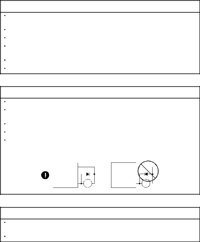
The surge absorbing diode installed on the DC output signal relay must be wired in the specified direction. Otherwise, the emergency stop and other protective circuits may not operate.
Servo |
|
Servo |
|
|
Amplifier |
|
Amplifier |
|
|
COM |
|
COM |
|
|
(24VDC) |
|
(24VDC) |
|
|
Control |
|
Control |
|
|
output |
RA |
output |
RA |
|
signal |
signal |
|||
|
|
(3) Test run adjustment
 CAUTION
Before operation, check the parameter settings. Improper settings may cause some machines to perform unexpected operation.
The parameter settings must not be changed excessively. Operation will be insatiable.
A - 4

(4) Usage
 CAUTION
Provide an external emergency stop circuit to ensure that operation can be stopped and power switched off immediately.
Any person who is involved in disassembly and repair should be fully competent to do the work.
Before resetting an alarm, make sure that the run signal is off to prevent an accident. A sudden restart is made if an alarm is reset with the run signal on.
Do not modify the equipment.
Use a noise filter, etc. to minimize the influence of electromagnetic interference, which may be caused by electronic equipment used near the servo amplifier.
Use the servo amplifier with the specified servo motor.
The electromagnetic brake on the servo motor is designed to hold the motor shaft and should not be used for ordinary braking.
For such reasons as service life and mechanical structure (e.g. where a ballscrew and the servo motor are coupled via a timing belt), the electromagnetic brake may not hold the motor shaft. To ensure safety, install a stopper on the machine side.
(5) Corrective actions
 CAUTION
When it is assumed that a hazardous condition may take place at the occur due to a power failure or a product fault, use a servo motor with electromagnetic brake or an external brake mechanism for the purpose of prevention.
Configure the electromagnetic brake circuit so that it is activated not only by the servo amplifier signals but also by an external emergency stop signal.
Contacts must be open when |
|
servo-on signal is off, when an |
Circuit must be |
alarm (trouble) is present and when |
opened during |
an electromagnetic brake signal. |
emergency stop signal. |
Servo motor
RA EMG
24VDC
Electromagnetic brake
When any alarm has occurred, eliminate its cause, ensure safety, and deactivate the alarm before restarting operation.
When power is restored after an instantaneous power failure, keep away from the machine because the machine may be restarted suddenly (design the machine so that it is secured against hazard if restarted).
A - 5

(6) Maintenance, inspection and parts replacement
 CAUTION
With age, the electrolytic capacitor will deteriorate. To prevent a secondary accident due to a fault, it is recommended to replace the electrolytic capacitor every 10 years when used in general environment. Please consult our sales representative.
(7) Disposal
 CAUTION
Dispose of the product as general industrial waste.
(8) General instruction
To illustrate details, the equipment in the diagrams of this Instruction Manual may have been drawn without covers and safety guards. When the equipment is operated, the covers and safety guards must be installed as specified. Operation must be performed in accordance with this Instruction Manual.
A - 6
COMPLIANCE WITH EC DIRECTIVES
1. WHAT ARE EC DIRECTIVES?
The EC directives were issued to standardize the regulations of the EU countries and ensure smooth distribution of safety-guaranteed products. In the EU countries, the machinery directive (effective in January, 1995), EMC directive (effective in January, 1996) and low voltage directive (effective in January, 1997) of the EC directives require that products to be sold should meet their fundamental safety requirements and carry the CE marks (CE marking). CE marking applies to machines and equipment into which servo amplifiers have been installed.
(1)EMC directive
The EMC directive applies not to the servo units alone but to servo-incorporated machines and equipment. This requires the EMC filters to be used with the servo-incorporated machines and equipment to comply with the EMC directive. For specific EMC directive conforming methods, refer to the EMC Installation Guidelines (IB(NA)67310).
This servo is certified by TUV, third-party assessment organization, to comply with the EMC directive in the conforming methods of the EMC Installation Guidelines.
(2)Low voltage directive
The low voltage directive applies also to servo units alone. Hence, they are designed to comply with the low voltage directive.
This servo is certified by TUV, third-party assessment organization, to comply with the low voltage directive.
(3)Machine directive
Not being machines, the servo amplifiers need not comply with this directive.
2. PRECAUTIONS FOR COMPLIANCE
(1)Servo amplifiers and servo motors used
Use the servo amplifiers and servo motors which comply with the standard model.
Servo amplifier series |
:MR-J2S-10A(1) to MR-J2S-350A(1) |
Servo motor series |
:HC-KFS |
|
HC-MFS |
|
HC-SFS |
|
HC-RFS |
|
HC-UFS |
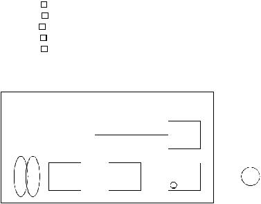
(2) Configuration
|
|
|
|
Control box |
|
|
|
|
|
|
|
|
|
|
|
|
|
||
|
|
|
|
|
|
|
|
|
Reinforced |
|
|
||||||||
|
|
|
|
|
|
|
|
|
insulating type |
|
|
||||||||
|
|
|
|
|
|
|
|
|
|
|
|
|
|
|
|
|
|
||
Reinforced |
|
|
|
|
|
|
|
|
|
|
24VDC |
|
|
|
|||||
|
|
|
|
|
|
|
|
|
|
power |
|
|
|
||||||
insulating |
No-fuse |
|
|
|
|
|
|
|
|
|
|
|
|
||||||
|
|
Magnetic |
|
|
|
|
|
|
supply |
|
|
|
|||||||
transformer |
|
|
|
|
|
|
|
|
|
Servo |
|||||||||
breaker |
|
|
contactor |
|
|
|
|
|
|
|
|
|
|
|
|||||
|
|
|
|
|
|
|
|
|
|
|
|
|
|||||||
|
|
|
|
|
|
|
|
|
|
|
|
|
|
|
|
||||
|
|
|
|
|
|
|
|
|
|
|
|
|
|
|
|
|
|
motor |
|
|
|
|
|
|
|
|
|
|
|
|
|
Servo |
|
|
|
|
|||
|
|
|
NFB |
|
|
MC |
|
|
|
|
|
amplifier |
|
|
SM |
||||
|
|
|
|
|
|
|
|
|
|
|
|
||||||||
|
|
|
|
|
|
|
|
|
|
|
|
|
|
|
|
|
|
|
|
|
|
|
|
|
|
|
|
|
|
|
|
|
|
|
|
|
|
|
|
|
|
|
|
|
|
|
|
|
|
|
|
|
|
|
|
|
|
|
|
|
|
|
|
|
|
|
|
|
|
|
|
|
|
|
|
|
|
|
|
|
|
|
|
|
|
|
|
|
|
|
|
|
|
|
|
|
|
|
|
|
|
|
|
|
|
|
|
|
|
|
|
|
|
|
|
|
|
|
|
(3)Environment
Operate the servo amplifier at or above the contamination level 2 set forth in IEC664. For this purpose, install the servo amplifier in a control box which is protected against water, oil, carbon, dust, dirt, etc. (IP54).
A - 7
(4)Power supply
(a)Operate the servo amplifier to meet the requirements of the overvoltage category II set forth in IEC664. For this purpose, a reinforced insulating transformer conforming to the IEC or EN Standard should be used in the power input section.
(b)When supplying interface power from external, use a 24VDC power supply which has been insulation-reinforced in I/O.
(5)Grounding
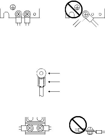
(a)To prevent an electric shock, always connect the protective earth (PE) terminals (marked  ) of the servo amplifier to the protective earth (PE) of the control box.
(b)Do not connect two ground cables to the same protective earth (PE) terminal. Always connect the cables to the terminals one-to-one.
PE terminals |
PE terminals |
(c)If a leakage current breaker is used to prevent an electric shock, the protective earth (PE) terminals of the servo amplifier must be connected to the corresponding earth terminals.
(6)Wiring
(a)The cables to be connected to the terminal block of the servo amplifier must have crimping terminals provided with insulating tubes to prevent contact with adjacent terminals.
Crimping terminal
Insulating tube
Cable
(b)When the servo motor has a power supply lead, use a fixed terminal block to connect it with the servo amplifier. Do not connect cables directly.
Terminal block
A - 8

(7)Auxiliary equipment and options
(a)The no-fuse breaker and magnetic contactor used should be the EN or IEC standard-compliant products of the models described in Section 13.2.2.
(b)The sizes of the cables described in Section 13.2.1 meet the following requirements. To meet the other requirements, follow Table 5 and Appendix C in EN60204-1.
Ambient temperature: 40 (104) [ (
( )] Sheath: PVC (polyvinyl chloride)
Installed on wall surface or open table tray
(c)Use the EMC filter for noise reduction. The radio noise filter (FR-BIF) is not required.
(8)Performing EMC tests
When EMC tests are run on a machine/device into which the servo amplifier has been installed, it must conform to the electromagnetic compatibility (immunity/emission) standards after it has satisfied the operating environment/electrical equipment specifications.
For the other EMC directive guidelines on the servo amplifier, refer to the EMC Installation Guidelines(IB(NA)67310).
A - 9
CONFORMANCE WITH UL/C-UL STANDARD
(1)Servo amplifiers and servo motors used
Use the servo amplifiers and servo motors which comply with the standard model.
Servo amplifier series |
:MR-J2S-10A(1) to MR-J2S-350A(1) |
Servo motor series |
:HC-KFS |
|
HC-MFS |
|
HC-SFS |
|
HC-RFS |
|
HC-UFS |
(2)Installation
Install a fan of 100CFM air flow 10.16 cm (4 in) above the servo amplifier or provide cooling of at least equivalent capability.
(3)Short circuit rating
This servo amplifier conforms to the circuit whose peak current is limited to 5000A or less. Having been subjected to the short-circuit tests of the UL in the alternating-current circuit, the servo amplifier conforms to the above circuit.
(4)Capacitor discharge time
The capacitor discharge time is as listed below. To ensure safety, do not touch the charging section for 10 minutes after power-off.
Servo amplifier |
Discharge time |
|
[min] |
||
|
||
MR-J2S-10A(1) 20A(1) |
1 |
|
MR-J2S-40A(1) 60A |
2 |
|
MR-J2S-70A to 350A |
3 |
(5)Options and auxiliary equipment
Use UL/C-UL standard-compliant products.
<<About the manuals>>
This Instruction Manual and the MELSERVO Servo Motor Instruction Manual are required if you use the General-Purpose AC servo MR-J2S-A for the first time. Always purchase them and use the MR- J2S-A safely.
Relevant manuals
Manual name |
Manual No. |
MELSERVO-J2-Super Series To Use the AC Servo Safely |
IB(NA)0300010 |
MELSERVO Servo Motor Instruction Manual |
SH(NA)3181 (Ver-D or later) |
EMC Installation Guidelines |
IB(NA)67310 |
A - 10
|
CONTENTS |
|
|
|
|
1. FUNCTIONS AND CONFIGURATION |
1- 1 to 1-12 |
|
1.1 |
Introduction.............................................................................................................................................. |
1- 1 |
1.2 |
Function block diagram .......................................................................................................................... |
1- 2 |
1.3 |
Servo amplifier standard specifications ................................................................................................ |
1- 3 |
1.4 |
Function list ............................................................................................................................................. |
1- 4 |
1.5 |
Model code definition .............................................................................................................................. |
1- 5 |
1.6 |
Combination with servo motor............................................................................................................... |
1- 6 |
1.7 |
Parts identification.................................................................................................................................. |
1- 7 |
1.8 |
Servo system with auxiliary equipment............................................................................................... |
1-10 |
|
|
|
2. INSTALLATION |
2- 1 to 2- 4 |
|
|
|
|
2.1 |
Environmental conditions....................................................................................................................... |
2- 1 |
2.2 |
Installation direction and clearances .................................................................................................... |
2- 2 |
2.3 |
Keep out foreign materials ..................................................................................................................... |
2- 3 |
2.4 |
Cable stress .............................................................................................................................................. |
2- 4 |
|
|
|
3. SIGNALS AND WIRING |
3- 1 to 3- 58 |
|
3.1 |
Standard connection example ................................................................................................................ |
3- 2 |
3.1.1 Position control mode ....................................................................................................................... |
3- 2 |
|
3.1.2 Speed control mode........................................................................................................................... |
3- 6 |
|
3.1.3 Torque control mode......................................................................................................................... |
3- 8 |
|
3.2 |
Internal connection diagram of servo amplifier .................................................................................. |
3-10 |
3.3 |
I/O signals................................................................................................................................................ |
3-11 |
3.3.1 Connectors and signal arrangements............................................................................................ |
3-11 |
|
3.3.2 Signal explanations ......................................................................................................................... |
3-14 |
|
3.4 |
Detailed description of the signals........................................................................................................ |
3-23 |
3.4.1 Position control mode ...................................................................................................................... |
3-23 |
|
3.4.2 Speed control mode.......................................................................................................................... |
3-28 |
|
3.4.3 Torque control mode........................................................................................................................ |
3-30 |
|
3.4.4 Position/speed control change mode .............................................................................................. |
3-33 |
|
3.4.5 Speed/torque control change mode................................................................................................. |
3-35 |
|
3.4.6 Torque/position control change mode ............................................................................................ |
3-37 |
|
3.5 |
Alarm occurrence timing chart ............................................................................................................. |
3-38 |
3.6 |
Interfaces................................................................................................................................................. |
3-39 |
3.6.1 Common line .................................................................................................................................... |
3-39 |
|
3.6.2 Detailed description of the interfaces ............................................................................................ |
3-40 |
|
3.7 |
Input power supply circuit..................................................................................................................... |
3-45 |
3.7.1 Connection example......................................................................................................................... |
3-45 |
|
3.7.2 Terminals.......................................................................................................................................... |
3-46 |
|
3.7.3 Power-on sequence........................................................................................................................... |
3-47 |
|
3.8 |
Connection of servo amplifier and servo motor ................................................................................... |
3-48 |
3.8.1 Connection instructions .................................................................................................................. |
3-48 |
|
3.8.2 Connection diagram......................................................................................................................... |
3-48 |
|
3.8.3 I/O terminals .................................................................................................................................... |
3-50 |
|
1
3.9 |
Servo motor with electromagnetic brake ............................................................................................. |
3-52 |
3.10 Grounding ............................................................................................................................................. |
3-55 |
|
3.11 Servo amplifier terminal block (TE2) wiring method....................................................................... |
3-56 |
|
3.12 Instructions for the 3M connector....................................................................................................... |
3-57 |
|
|
|
|
4. OPERATION |
4- 1 to 4- 6 |
|
4.1 When switching power on for the first time.......................................................................................... |
4- 1 |
|
4.2 |
Startup...................................................................................................................................................... |
4- 2 |
4.2.1 Selection of control mode.................................................................................................................. |
4- 2 |
|
4.2.2 Position control mode ....................................................................................................................... |
4- 2 |
|
4.2.3 Speed control mode........................................................................................................................... |
4- 4 |
|
4.2.4 Torque control mode......................................................................................................................... |
4- 5 |
|
4.3 |
Multidrop communication ...................................................................................................................... |
4- 6 |
|
|
|
5. PARAMETERS |
5- 1 to 5- 32 |
|
5.1 |
Parameter list .......................................................................................................................................... |
5- 1 |
5.1.1 Parameter write inhibit ................................................................................................................... |
5- 1 |
|
5.1.2 Lists.................................................................................................................................................... |
5- 2 |
|
5.2 |
Detailed description ............................................................................................................................... |
5-25 |
5.2.1 Electronic gear ................................................................................................................................. |
5-25 |
|
5.2.2 Analog output................................................................................................................................... |
5-29 |
|
5.2.3 Using forward/reverse rotation stroke end to change the stopping pattern.............................. |
5-30 |
|
5.2.4 Alarm history clear.......................................................................................................................... |
5-30 |
|
5.2.5 Position smoothing .......................................................................................................................... |
5-31 |
|
|
|
|
6. DISPLAY AND OPERATION |
6- 1 to 6-16 |
|
6.1 |
Display flowchart..................................................................................................................................... |
6- 1 |
6.2 |
Status display .......................................................................................................................................... |
6- 2 |
6.2.1 Display examples.............................................................................................................................. |
6- 2 |
|
6.2.2 Status display list ............................................................................................................................. |
6- 3 |
|
6.2.3 Changing the status display screen................................................................................................ |
6- 4 |
|
6.3 |
Diagnostic mode....................................................................................................................................... |
6- 5 |
6.4 Alarm mode.............................................................................................................................................. |
6- 7 |
|
6.5 Parameter mode ...................................................................................................................................... |
6- 8 |
|
6.6 |
External I/O signal display..................................................................................................................... |
6- 9 |
6.7 |
Output signal forced output (DO forced output) ................................................................................. |
6-12 |
6.8 |
Test operation mode ............................................................................................................................... |
6-13 |
6.8.1 Mode change..................................................................................................................................... |
6-13 |
|
6.8.2 Jog operation .................................................................................................................................... |
6-14 |
|
6.8.3 Positioning operation....................................................................................................................... |
6-15 |
|
6.8.4 Motor-less operation........................................................................................................................ |
6-16 |
|
|
|
|
7. GENERAL GAIN ADJUSTMENT |
7- 1 to 7-12 |
|
7.1 |
Different adjustment methods ............................................................................................................... |
7- 1 |
7.1.1 Adjustment on a single servo amplifier.......................................................................................... |
7- 1 |
|
2
7.1.2 Adjustment using servo configuration software............................................................................ |
7- 2 |
7.2 Auto tuning .............................................................................................................................................. |
7- 3 |
7.2.1 Auto tuning mode ............................................................................................................................. |
7- 3 |
7.2.2 Auto tuning mode operation ............................................................................................................ |
7- 4 |
7.2.3 Adjustment procedure by auto tuning............................................................................................ |
7- 5 |
7.2.4 Response level setting in auto tuning mode................................................................................... |
7- 6 |
7.3 Manual mode 1 (simple manual adjustment)....................................................................................... |
7- 7 |
7.3.1 Operation of manual mode 1 ........................................................................................................... |
7- 7 |
7.3.2 Adjustment by manual mode 1 ....................................................................................................... |
7- 7 |
7.4 Interpolation mode ................................................................................................................................. |
7-10 |
7.5 Differences in auto tuning between MELSERVO-J2 and MELSERVO-J2-Super .......................... |
7-11 |
7.5.1 Response level setting ..................................................................................................................... |
7-11 |
7.5.2 Auto tuning selection....................................................................................................................... |
7-11 |
|
|
8. SPECIAL ADJUSTMENT FUNCTIONS |
8- 1 to 8-10 |
8.1 Machine resonance suppression filter and adaptive vibration suppression control......................... |
8- 1 |
8.1.1 Function block diagram.................................................................................................................... |
8- 1 |
8.1.2 Machine resonance suppression filter ............................................................................................ |
8- 1 |
8.1.3 Adaptive vibration suppression control.......................................................................................... |
8- 3 |
8.2 Low-pass filter ......................................................................................................................................... |
8- 4 |
8.3 Gain changing function........................................................................................................................... |
8- 5 |
8.3.1 Applications....................................................................................................................................... |
8- 5 |
8.3.2 Function block diagram.................................................................................................................... |
8- 5 |
8.3.3 Parameters ........................................................................................................................................ |
8- 6 |
8.3.4 Gain changing operation.................................................................................................................. |
8- 8 |
|
|
9. INSPECTION |
9- 1 to 9- 2 |
|
|
|
|
10. TROUBLESHOOTING |
10- 1 to 10-12 |
|
|
10.1 Trouble at start-up .............................................................................................................................. |
10- 1 |
10.1.1 Position control mode ................................................................................................................... |
10- 1 |
10.1.2 Speed control mode....................................................................................................................... |
10- 4 |
10.1.3 Torque control mode..................................................................................................................... |
10- 5 |
10.2 When alarm or warning has occurred ............................................................................................... |
10- 6 |
10.2.1 Alarms and warning list .............................................................................................................. |
10- 6 |
10.2.2 Remedies for alarms..................................................................................................................... |
10- 7 |
10.2.3 Remedies for warnings................................................................................................................ |
10-12 |
|
|
11. OUTLINE DIMENSION DRAWINGS |
11- 1 to 11- 6 |
11.1 Servo amplifiers................................................................................................................................... |
11- 1 |
11.2 Connectors............................................................................................................................................ |
11- 4 |
|
|
12. CHARACTERISTICS |
12- 1 to 12- 6 |
|
|
12.1 Overload protection characteristics................................................................................................... |
12- 1 |
12.2 Power supply equipment capacity and generated loss .................................................................... |
12- 2 |
3
12.3 |
Dynamic brake characteristics........................................................................................................... |
12- 4 |
12.4 |
Encoder cable flexing life .................................................................................................................... |
12- 6 |
|
|
|
13. OPTIONS AND AUXILIARY EQUIPMENT |
13- 1 to 13-30 |
|
13.1 |
Options.................................................................................................................................................. |
13- 1 |
13.1.1 Regenerative brake options ......................................................................................................... |
13- 1 |
|
13.1.2 Cables and connectors.................................................................................................................. |
13- 5 |
|
13.1.3 Junction terminal block (MR-TB20) .......................................................................................... |
13-13 |
|
13.1.4 Maintenance junction card (MR-J2CN3TM) ............................................................................ |
13-15 |
|
13.1.5 Battery (MR-BAT, A6BAT)......................................................................................................... |
13-16 |
|
13.1.6 Servo configurations software .................................................................................................... |
13-17 |
|
13.2 |
Auxiliary equipment .......................................................................................................................... |
13-19 |
13.2.1 Recommended wires.................................................................................................................... |
13-19 |
|
13.2.2 No-fuse breakers, fuses, magnetic contactors........................................................................... |
13-21 |
|
13.2.3 Power factor improving reactors ................................................................................................ |
13-21 |
|
13.2.4 Relays............................................................................................................................................ |
13-22 |
|
13.2.5 Surge absorbers ........................................................................................................................... |
13-22 |
|
13.2.6 Noise reduction techniques......................................................................................................... |
13-22 |
|
13.2.7 Leakage current breaker............................................................................................................. |
13-28 |
|
13.2.8 EMC filter..................................................................................................................................... |
13-30 |
|
|
|
|
14. COMMUNICATION FUNCTIONS |
14- 1 to 1428 |
|
|
|
|
14.1 |
Configuration ....................................................................................................................................... |
14- 1 |
14.1.1 RS-422 configuration.................................................................................................................... |
14- 1 |
|
14.1.2 RS-232C configuration ................................................................................................................. |
14- 2 |
|
14.2 |
Communication specifications............................................................................................................ |
14- 3 |
14.2.1 Communication overview............................................................................................................. |
14- 3 |
|
14.2.2 Parameter setting......................................................................................................................... |
14- 4 |
|
14.3 |
Protocol ................................................................................................................................................. |
14- 5 |
14.4 |
Character codes ................................................................................................................................... |
14- 7 |
14.5 |
Error codes ........................................................................................................................................... |
14- 8 |
14.6 Checksum ............................................................................................................................................. |
14- 8 |
|
14.7 |
Time-out operation .............................................................................................................................. |
14- 9 |
14.8 |
Retry operation .................................................................................................................................... |
14- 9 |
14.9 |
Initialization........................................................................................................................................ |
14-10 |
14.10 Communication procedure example ............................................................................................... |
14-10 |
|
14.11 Command and data No. list............................................................................................................. |
14-11 |
|
14.11.1 Read commands......................................................................................................................... |
14-11 |
|
14.11.2 Write commands........................................................................................................................ |
14-12 |
|
14.12 Detailed explanations of commands............................................................................................... |
14-14 |
|
14.12.1 Data processing.......................................................................................................................... |
14-14 |
|
14.12.2 Status display ............................................................................................................................ |
14-16 |
|
14.12.3 Parameter................................................................................................................................... |
14-17 |
|
14.12.4 External I/O pin statuses (DIO diagnosis).............................................................................. |
14-19 |
|
14.12.5 Disable/enable of external I/O signals (DIO) .......................................................................... |
14-20 |
|
14.12.6 External input signal ON/OFF (test operation) ..................................................................... |
14-21 |
|
14.12.7 Test operation mode .................................................................................................................. |
14-22 |
|
4
14.12.8 Output signal pin ON/OFF (DO forced output)...................................................................... |
14-24 |
|
14.12.9 Alarm history ............................................................................................................................. |
14-25 |
|
14.12.10 Current alarm.......................................................................................................................... |
14-26 |
|
14.12.11 Other commands...................................................................................................................... |
14-27 |
|
|
|
|
15. ABSOLUTE POSITION DETECTION SYSTEM |
15- 1 to 1566 |
|
15.1 Outline.................................................................................................................................................. |
15- 1 |
|
15.1.1 Features......................................................................................................................................... |
15- 1 |
|
15.1.2 Restrictions.................................................................................................................................... |
15- 1 |
|
15.2 |
Specifications ....................................................................................................................................... |
15- 2 |
15.3 |
Battery installation procedure ........................................................................................................... |
15- 3 |
15.4 |
Standard connection diagram ............................................................................................................ |
15- 4 |
15.5 |
Signal explanation............................................................................................................................... |
15- 5 |
15.6 |
Startup procedure................................................................................................................................ |
15- 6 |
15.7 |
Absolute position data transfer protocol ........................................................................................... |
15- 7 |
15.7.1 Data transfer procedure............................................................................................................... |
15- 7 |
|
15.7.2 Transfer method ........................................................................................................................... |
15- 8 |
|
15.7.3 Home position setting.................................................................................................................. |
15-17 |
|
15.7.4 Use of servo motor with electromagnetic brake ....................................................................... |
15-19 |
|
15.7.5 How to process the absolute position data at detection of stroke end.................................... |
15-20 |
|
15.8 |
Examples of use .................................................................................................................................. |
15-21 |
15.8.1 MELSEC-A1S (A1SD71)............................................................................................................. |
15-21 |
|
15.8.2 MELSEC FX(2N)-32MT (FX(2N)-1PG)........................................................................................ |
15-35 |
|
15.8.3 MELSEC A1SD75(AD75) ........................................................................................................... |
15-48 |
|
15.9 |
Confirmation of absolute position detection data............................................................................ |
15-63 |
15.10 Absolute position data transfer errors ........................................................................................... |
15-64 |
|
15.10.1 Corrective actions ...................................................................................................................... |
15-64 |
|
15.10.2 Error resetting conditions......................................................................................................... |
15-66 |
|
|
|
|
Appendix |
App- 1 to App- 4 |
|
App 1. Signal arrangement recording sheets......................................................................................... |
App- 1 |
|
App 2. Analog monitor block diagram .................................................................................................... |
App- 2 |
|
App 3. Status display block diagram ...................................................................................................... |
App- 3 |
|
5

Optional Servo Motor Instruction Manual CONTENTS
The rough table of contents of the optional MELSERVO Servo Motor Instruction Manual is introduced here for your reference. Note that the contents of the Servo Motor Instruction Manual are not included in the Servo Amplifier Instruction Manual.
1.INTRODUCTION
2.INSTALLATION
3.CONNECTORS USED FOR SERVO MOTOR WIRING
4.INSPECTION
5.SPECIFICATIONS
6.CHARACTERISTICS
7.OUTLINE DIMENSION DRAWINGS
8.CALCULATION METHODS FOR DESIGNING
6

1.FUNCTIONS AND CONFIGURATION
1.FUNCTIONS AND CONFIGURATION
1.1 Introduction
The Mitsubishi MELSERVO-J2-Super series general-purpose AC servo is based on the MELSERVO-J2 series and has further higher performance and higher functions.
It has position control, speed control and torque control modes. Further, it can perform operation with the control modes changed, e.g. position/speed control, speed/torque control and torque/position control. Hence, it is applicable to a wide range of fields, not only precision positioning and smooth speed control of machine tools and general industrial machines but also line control and tension control.
As this new series has the RS-232C or RS-422 serial communication function, a servo configuration software-installed personal computer or the like can be used to perform parameter setting, test operation, status display monitoring, gain adjustment, etc.
With real-time auto tuning, you can automatically adjust the servo gains according to the machine.
The MELSERVO-J2-Super series servo motor is equipped with an absolute position encoder which has the resolution of 131072 pulses/rev to ensure more accurate control as compared to the MELSERVO-J2 series. Simply adding a battery to the servo amplifier makes up an absolute position detection system. This makes home position return unnecessary at power-on or alarm occurrence by setting a home position once.
(1)Position control mode
An up to 500kpps high-speed pulse train is used to control the speed and direction of a motor and execute precision positioning of 131072 pulses/rev resolution.
The position smoothing function provides a choice of two different modes appropriate for a machine, so a smoother start/stop can be made in response to a sudden position command.
A torque limit is imposed on the servo amplifier by the clamp circuit to protect the power transistor in the main circuit from overcurrent due to sudden acceleration/deceleration or overload. This torque limit value can be changed to any value with an external analog input or the parameter.
(2)Speed control mode
An external analog speed command (0 to  10VDC) or parameter-driven internal speed command (max. 7 speeds) is used to control the speed and direction of a servo motor smoothly.
There are also the acceleration/deceleration time constant setting in response to speed command, the servo lock function at a stop time, and automatic offset adjustment function in response to external analog speed command.
(3)Torque control mode
An external analog torque command (0 to  8VDC) or parameter-driven internal torque command is used to control the torque output by the servo motor.
To protect misoperation under no load, the speed limit function (external or internal setting) is also available for application to tension control, etc.
1 - 1
1. FUNCTIONS AND CONFIGURATION
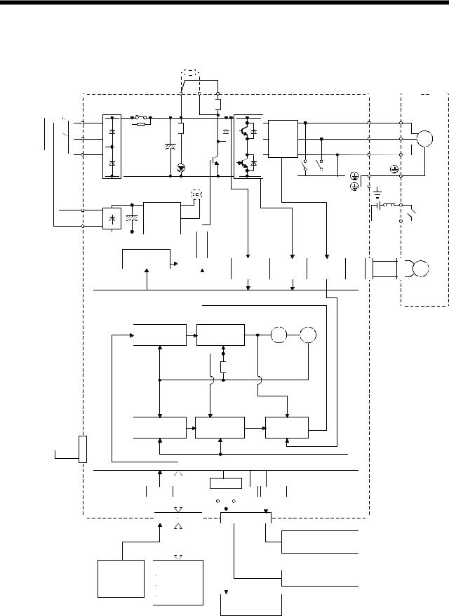
1.2 Function block diagram
The function block diagram of this servo is shown below.
Regenerative brake option
(Note2)
Power NFB MC supply 


 3-phase
 200 to


 230VAC,


 1-phase
230VACor 1-phase 100to120VAC
Servo amplifier |
P |
C |
D |
|
|
|
Servo motor |
|
DS |
RA |
|
(Note1) |
|
|
|
|
|
|
|
|
U |
|
U |
|
||
L1 |
|
|
|
|
|
|
||
L2 |
Regenerative |
|
Current |
V |
|
V |
|
|
brake |
|
|
SM |
|||||
|
transistor |
|
detector |
|
|
|
||
|
|
W |
|
W |
|
|||
L3 |
CHARGE |
|
|
|
|
|||
|
|
lamp |
|
|
|
|
|
|
|
|
Fan |
|
|
Dynamic |
|
|
|
|
|
|
|
brake |
|
|
|
|
(MR-J2S-200A or more) |
|
|
|
|
|
|
||
|
|
|
|
E1 |
|
Electro- |
||
L11 |
|
|
|
|
|
|
||
Control |
|
|
|
|
|
|
||
|
|
|
|
|
|
magnetic |
||
|
|
|
|
|
E2 |
|
||
|
power |
|
|
|
|
|
||
L21 |
|
|
|
|
|
brake |
||
|
|
|
|
|
|
|||
supply |
|
|
|
|
|
|
||
|
|
|
|
|
|
|
|
|
Regenerative |
|
|
|
brake |
Base amplifier Voltage |
Overcurrent |
Current |
|
detection |
protection |
detection |
 CN2
CN2
Encoder
Pulse |
|
|
Virtual |
|
|
|
encoder |
||
input |
Model position |
Model speed |
||
|
||||
|
control |
control |
|
|
|
|
|
Virtual |
|
|
|
|
motor |
|
|
Model |
Model |
Model torque |
|
|
position |
speed |
|
|
|
Actual position |
Actual speed |
Current |
|
|
control |
control |
control |
MR-BAT |
CON1 |
||
Optional battery |
|
|
|
|
|
||
|
|
|
|
|
|
|
|
(for absolute position)
|
|
|
RS-232C |
|||||||
|
A/D |
|
|
|
RS-422 |
|
D/A |
|||
|
|
|||||||||
|
|
I/F |
|
|
|
|
|
|
|
|
|
|
|
|
|
|
|
|
|
|
|
|
|
|
|
|
|
|
|
|
|
|
|
CN1A CN1B |
|
|
|
|
CN3 |
|
|||
|
|
|
|
|
|
|
|
|
|
Analog monitor |
|
|
|
|
|
|
|
|
|
|
|
|
|
|
|
|
|
|
|
|
|
(2 channels) |
|
D I/O control |
|
|
|
|
|
|
|
Controller |
|
Analog |
|
Servo on |
|
|
|
|
|
|
|
RS-422/RS-232C |
(2 channels) |
|
Start |
|
|
|
|
|
|
|
|
|
|
|
|
|
|
|
|
|
||
|
|
Failure, etc. |
|
|
|
|
|
|
|
|
|
|
|
|
To other servo |
||||||
|
|
|
|
|
|
|||||
|
|
|
|
|
|
amplifier |
||||
Note:1. The built-in regenerative brake resistor is not provided for the MR-J2S-10A(1).
2.For 1-phase 230VAC, connect the power supply to L1,L2 and leave L3 open. L3 is not provided for a 1-phase 100 to120VAC power supply.
1 - 2
1. FUNCTIONS AND CONFIGURATION
1.3 Servo amplifier standard specifications
|
|
|
Servo Amplifier MR-J2S- |
|
10A |
|
|
|
20A |
|
40A |
|
|
60A |
|
|
70A |
|
100A |
200A |
|
350A |
10A1 |
20A1 |
40A1 |
||||||||||||||||
Item |
|
|
|
|
|
|
|
|
|
|
|
|
|
|
|
||||||||||||||||||||||||||
|
|
|
|
|
|
|
|
|
|
|
|
|
|
|
|
|
|
|
|
|
|
|
|
|
|
|
|
|
|
|
|
|
|
|
|
|
|
|
|
|
|
supply |
Voltage/frequency |
|
3-phase 200 to 230VAC, 50/60Hz or |
|
3-phase 200 to |
|
|
|
1-phase 100 to |
|
|||||||||||||||||||||||||||||||
|
3-phase 200 to 230VAC:170 to 253VAC |
|
3-phase 170 to |
|
|
|
1-phase |
|
|
|
|||||||||||||||||||||||||||||||
|
|
|
|
|
|
|
|
|
|
|
|||||||||||||||||||||||||||||||
|
|
|
|
|
1-phase 230VAC, 50/60Hz |
|
|
|
|
|
230VAC, 50/60Hz |
120VAC 50/60Hz |
|||||||||||||||||||||||||||||
Power |
Permissible voltage fluctuation |
|
1-phase 230VAC: 207 to 253VAC |
|
|
|
|
|
253VAC |
|
|
|
85 to 127VAC |
|
|||||||||||||||||||||||||||
|
|
|
|
|
|
|
|
|
|
|
|
|
|||||||||||||||||||||||||||||
Permissible frequency fluctuation |
|
|
|
|
|
|
|
|
|
|
|
|
|
|
|
|
|
|
|
|
|
Within |
|
5% |
|
|
|
|
|
|
|
|
|
||||||||
|
|
|
|
|
|
|
|
|
|
|
|
|
|
|
|
|
|
|
|
|
|
|
|
|
|
||||||||||||||||
|
|
|
|
|
|
|
|
|
|
|
|
|
|
|
|
|
|
|
|
|
|
|
|
|
|
||||||||||||||||
|
Power supply capacity |
|
|
|
|
|
|
|
|
|
|
|
|
|
|
|
|
|
Refer to Section12.2 |
|
|
|
|
|
|
|
|||||||||||||||
System |
|
|
|
|
|
|
|
|
|
|
|
|
|
Sine-wave PWM control, current control system |
|
|
|
||||||||||||||||||||||||
Dynamic brake |
|
|
|
|
|
|
|
|
|
|
|
|
|
|
|
|
|
|
|
|
|
|
Built-in |
|
|
|
|
|
|
|
|
|
|
||||||||
|
|
|
|
|
Overcurrent shut-off, regenerative overvoltage shut-off, overload shut-off (electronic |
||||||||||||||||||||||||||||||||||||
Protective functions |
|
thermal relay), servo motor overheat protection, encoder error protection, regenerative |
|||||||||||||||||||||||||||||||||||||||
|
brake error protection, undervoltage, instantaneous power failure protection, overspeed |
||||||||||||||||||||||||||||||||||||||||
|
|
|
|
|
|||||||||||||||||||||||||||||||||||||
|
|
|
|
|
protection, excessive error protection |
|
|
|
|
|
|
|
|
|
|
|
|
|
|
|
|
||||||||||||||||||||
Speed frequency response |
|
|
|
|
|
|
|
|
|
|
|
|
|
|
|
|
|
|
|
|
550Hz or more |
|
|
|
|
|
|
|
|||||||||||||
mode |
Max. input pulse frequency |
|
|
|
|
|
|
|
500kpps (for differential receiver), 200kpps (for open collector) |
|
|||||||||||||||||||||||||||||||
|
|
|
|
|
|
|
|
|
|
|
|
|
|
|
|
|
|
|
|
|
|
|
|
|
|
|
|
|
|
|
|
|
|
|
|
|
|
|
|
|
|
Command pulse multiplying factor |
|
|
|
|
|
|
Electronic gear A:1 to 65535 |
131072 B:1 to 65535, 1/50 A/B |
500 |
|
|
||||||||||||||||||||||||||||||
control |
|
|
|
|
|
|
|
|
|||||||||||||||||||||||||||||||||
|
|
|
|
|
|
|
|
|
|
|
|
|
|
|
|
|
|
|
|
|
|
|
|
|
|
|
|
|
|
|
|
|
|
|
|
|
|
|
|
|
|
In-position range setting |
|
|
|
|
|
|
|
|
|
|
|
|
|
0 to |
|
10000 pulse (command pulse unit) |
|
|
|
|
|||||||||||||||||||||
Position |
|
|
|
|
|
|
|
|
|
|
|
|
|
|
|
|
|
|
|||||||||||||||||||||||
|
|
|
|
|
|
|
|
|
|
|
|
|
|
|
|
|
|||||||||||||||||||||||||
|
|
|
|
|
|
|
|
|
|
|
|
|
|
|
|
|
|
|
|
|
|
|
|
|
|
|
|
|
|
|
|
|
|
|
|
|
|
|
|
|
|
Error excessive |
|
|
|
|
|
|
|
|
|
|
|
|
|
|
|
|
|
|
|
|
|
10 revolutions |
|
|
|
|
|
|
|
||||||||||||
|
|
|
|
|
|
|
|
|
|
|
|
|
|
|
|
|
|
|
|
|
|
|
|
|
|
|
|
|
|||||||||||||
|
|
|
|
|
|
|
|
|
|
|
|
|
|
|
|
|
|
|
|
|
|
|
|
|
|
|
|
|
|||||||||||||
|
|
|
|
|
|
|
|
|
|
|
|
|
|
|
|
|
|
|
|
|
|
|
|
|
|
|
|
||||||||||||||
|
Torque limit |
|
|
Set by parameter setting or external analog input (0 to |
10VDC/maximum torque) |
||||||||||||||||||||||||||||||||||||
|
|
|
|
|
|
|
|
|
|
|
|
|
|
|
|
|
|
|
|
|
|
|
|
|
|
|
|
|
|
|
|
|
|||||||||
mode |
Speed control range |
|
|
|
|
|
|
|
Analog speed command 1: 2000, internal speed command 1: 5000 |
|
|||||||||||||||||||||||||||||||
|
|
|
|
|
|
|
|
|
|
|
|
|
|
|
|
|
|
|
|
|
|
|
|
|
|
|
|
|
|
|
|
|
|
|
|
|
|
|
|
|
|
Analog speed command input |
|
|
|
|
|
|
|
|
|
|
|
|
|
|
|
|
0 to |
|
|
10VDC / Rated speed |
|
|
|
|
|
|
|
||||||||||||||
|
|
|
|
|
|
|
|
|
|
|
|
|
|
|
|
|
|
|
|
|
|
|
|
|
|||||||||||||||||
control |
|
|
|
|
|
|
|
|
|
|
|
|
|
|
|
|
|
|
|
|
|
|
|
|
|
||||||||||||||||
|
|
|
|
|
|
|
|
|
|
|
|
|
|
|
|
|
|
|
|
|
|
|
|
|
|
|
|||||||||||||||
Speed fluctuation ratio |
|
|
|
|
|
|
|
|
|
|
|
|
|
|
0% or less (power fluctuation 10%) |
|
|
|
|
||||||||||||||||||||||
Speed |
|
|
|
|
|
|
|
|
|
|
|
|
|
|
|
|
0.01% or less (load fluctuation 0 to 100%) |
|
|
|
|
||||||||||||||||||||
|
|
|
|
|
|
|
|
|
|
|
|
|
|
|
|
|
|
|
|
|
|
|
|
|
|
|
|
|
|
|
|
|
|
|
|
|
|
|
|
|
|
|
|
|
|
|
|
|
|
|
|
0.2% max.(ambient temperature 25 |
|
10 |
) for external speed setting only |
|
|||||||||||||||||||||||||||
|
|
|
|
|
|
|
|
|
|
|
|
|
|||||||||||||||||||||||||||||
|
|
|
|
|
|
|
|
|
|
|
|
|
|||||||||||||||||||||||||||||
|
Torque limit |
|
|
Set by parameter setting or external analog input (0 to |
10VDC/maximum torque) |
||||||||||||||||||||||||||||||||||||
|
|
|
|
|
|
|
|
|
|
|
|
|
|
|
|
|
|
|
|
|
|
|
|
|
|
|
|
|
|
|
|
|
|
|
|
|
|
|
|
|
|
Torque |
Analog torque command input |
|
|
|
|
|
|
|
0 to |
|
8VDC / Maximum torque (input impedance 10 to 12k |
) |
|
|
|||||||||||||||||||||||||||
|
|
|
|
|
|
|
|
|
|
||||||||||||||||||||||||||||||||
control |
|
|
|
|
|
|
|
|
|
|
|||||||||||||||||||||||||||||||
|
|
|
|
|
|
|
|
|
|
|
|
|
|
|
|
|
|
|
|
|
|
|
|
|
|
|
|
|
|
|
|
|
|
|
|
|
|
|
|
||
Speed limit |
|
|
|
Set by parameter setting or external analog input (0 to |
|
10VDC/Rated speed) |
|||||||||||||||||||||||||||||||||||
mode |
|
|
|
|
|||||||||||||||||||||||||||||||||||||
|
|
||||||||||||||||||||||||||||||||||||||||
|
|
||||||||||||||||||||||||||||||||||||||||
|
|
|
|
|
|
|
|
|
|
|
|
|
|
|
|
|
|
|
|
|
|
|
|
|
|
|
|
|
|
|
|
|
|
|
|
|
|
|
|
||
Structure |
|
|
|
|
|
|
|
|
|
Self-cooled, open (IP00) |
|
|
|
|
|
|
Force-cooling, |
Self-cooled, open(IP00) |
|||||||||||||||||||||||
|
|
|
|
|
|
|
|
|
|
|
|
|
|
|
|
|
|
|
|
|
|
|
|
|
|
|
|
|
|
|
|
open (IP00) |
|
|
|
|
|||||
|
Ambient temperature |
|
0 to 55 [ ] (non-freezing) |
|
|
|
|
|
|
|
|
|
|
|
|
|
|
|
|
|
|
|
|
||||||||||||||||||
|
|
32 to |
131 [ |
] (non-freezing) |
|
|
|
|
|
|
|
|
|
|
|
|
|
|
|
|
|
|
|
|
|||||||||||||||||
|
|
|
|
|
|
|
|
|
|
|
|
|
|
|
|
|
|
|
|
|
|
|
|
|
|||||||||||||||||
|
Ambient humidity |
|
90%RH or less (non-condensing) |
|
|
|
|
|
|
|
|
|
|
|
|
|
|
|
|
|
|
|
|
||||||||||||||||||
Environment |
Ambient |
|
|
|
20 to 65 [ |
] (non-freezing) |
|
|
|
|
|
|
|
|
|
|
|
|
|
|
|
|
|
|
|
|
|||||||||||||||
|
|
|
|
|
|
|
|
|
|
|
|
|
|
|
|
|
|
|
|
|
|
|
|||||||||||||||||||
|
Storage temperature |
|
|
|
4 to |
149 [ |
] (non-freezing) |
|
|
|
|
|
|
|
|
|
|
|
|
|
|
|
|
|
|
|
|
||||||||||||||
|
|
|
|
|
|
|
|
|
|
|
|
|
|
|
|
|
|
|
|
|
|
|
|
|
|
|
|||||||||||||||
|
Storage humidity |
|
90%RH or less (non-condensing) |
|
|
|
|
|
|
|
|
|
|
|
|
|
|
|
|
|
|
|
|
||||||||||||||||||
|
|
|
|
|
Indoors (no direct sunlight) |
|
|
|
|
|
|
|
|
|
|
|
|
|
|
|
|
|
|
|
|
||||||||||||||||
|
|
|
|
|
Free from corrosive gas, flammable gas, oil mist, dust and dirt |
|
|
|
|
||||||||||||||||||||||||||||||||
|
Altitude |
|
Max. 1000m (3280ft) above sea level |
|
|
|
|
|
|
|
|
|
|
|
|
|
|
|
|
||||||||||||||||||||||
|
Vibration |
|
5.9 [m/s2] or less |
|
|
|
|
|
|
|
|
|
|
|
|
|
|
|
|
|
|
|
|
|
|
|
|
|
|
|
|
||||||||||
|
|
19.4 [ft/s2] or less |
|
|
|
|
|
|
|
|
|
|
|
|
|
|
|
|
|
|
|
|
|
|
|
|
|
|
|
|
|||||||||||
|
|
|
|
|
|
|
|
|
|
|
|
|
|
|
|
|
|
|
|
|
|
|
|
|
|
|
|
|
|
|
|
|
|||||||||
Weight |
|
|
[kg] |
0.7 |
|
0.7 |
|
|
1.1 |
|
1.1 |
|
1.7 |
|
1.7 |
|
2.0 |
|
|
2.0 |
0.7 |
0.7 |
|
1.1 |
|||||||||||||||||
|
|
[lb] |
1.5 |
|
|
1.5 |
|
|
2.4 |
|
|
2.4 |
|
3.75 |
|
3.75 |
4.4 |
|
|
4.4 |
1.5 |
1.5 |
|
2.4 |
|||||||||||||||||
|
|
|
|
|
|
|
|
|
|
|
|
|
|||||||||||||||||||||||||||||
1 - 3
1. FUNCTIONS AND CONFIGURATION
1.4 Function list
The following table lists the functions of this servo. For details of the functions, refer to the corresponding chapters and sections.
Function |
|
|
Description |
|
|
(Note) |
Refer to |
|||
|
|
|
|
Control mode |
||||||
|
|
|
|
|
|
|
|
|
||
|
|
|
|
|
|
|
|
|
Section 3.1.1 |
|
Position control mode |
This servo is used as position control servo. |
P |
Section 3.4.1 |
|||||||
|
|
|
|
|
|
|
|
|
Section 4.2.2 |
|
|
|
|
|
|
|
|
|
|
Section 3.1.2 |
|
Speed control mode |
This servo is used as speed control servo. |
S |
Section 3.4.2 |
|||||||
|
|
|
|
|
|
|
|
|
Section 4.2.3 |
|
|
|
|
|
|
|
|
|
|
Section 3.1.3 |
|
Torque control mode |
This servo is used as torque control servo. |
T |
Section 3.4.3 |
|||||||
|
|
|
|
|
|
|
|
|
Section 4.2.4 |
|
Position/speed control change |
Using external input signal, control can be switched |
P/S |
Section 3.4.4 |
|||||||
mode |
between position control and speed control. |
|||||||||
|
|
|||||||||
Speed/torque control change |
Using external input signal, control can be switched |
S/T |
Section 3.4.5 |
|||||||
mode |
between speed control and torque control. |
|||||||||
|
|
|||||||||
Torque/position control |
Using external input signal, control can be switched |
T/P |
Section 3.4.6 |
|||||||
change mode |
between torque control and position control. |
|||||||||
|
|
|||||||||
High-resolution encoder |
High-resolution encoder of 131072 pulses/rev is used as a |
P, S, T |
|
|||||||
servo motor encoder. |
|
|
|
|
|
|
||||
|
|
|
|
|
|
|
|
|||
Absolute position detection |
Merely setting a home position once makes home position |
P |
Chapter 15 |
|||||||
system |
return unnecessary at every power-on. |
|
||||||||
|
|
|
||||||||
|
You can switch between gains during rotation and gains |
|
|
|||||||
Gain changing function |
during stop or use an external signal to change gains |
P, S |
Section 8.3 |
|||||||
|
during operation. |
|
|
|
|
|
|
|
||
Adaptive vibration |
Servo amplifier detects mechanical resonance and sets filter |
|
|
|||||||
characteristics |
automatically |
to |
suppress mechanical |
P, S, T |
Section 8.1 |
|||||
suppression control |
||||||||||
vibration. |
|
|
|
|
|
|
|
|
||
|
|
|
|
|
|
|
|
|
||
Low-pass filter |
Suppresses high-frequency resonance which occurs as servo |
P, S, T |
Section 8.2 |
|||||||
system response is increased. |
|
|
|
|||||||
|
|
|
|
|
|
|||||
|
Analyzes the frequency characteristic of the mechanical |
|
|
|||||||
Machine analyzer function |
system by simply connecting a servo configuration software- |
P |
|
|||||||
|
installed personal computer and servo amplifier. |
|
|
|||||||
Machine simulation |
Can simulate |
machine |
motions on |
a |
personal computer |
P |
|
|||
screen on the basis of the machine analyzer results. |
|
|||||||||
|
|
|
||||||||
Gain search function |
Personal computer changes |
gains |
automatically and |
P |
|
|||||
searches for overshoot-free gains in a short time. |
|
|||||||||
|
|
|
||||||||
Slight vibration suppression |
Suppresses vibration of |
|
1 pulse produced at a servo motor |
P |
Section 7.5 |
|||||
|
||||||||||
control |
stop. |
|
|
|
|
|
|
|||
|
|
|
|
|
|
|
|
|||
Electronic gear |
Input pulses can be multiplied by 1/50 to 50. |
P |
Parameters No. 3, 4 |
|||||||
|
Automatically adjusts the gain to optimum value if load |
|
|
|||||||
Auto tuning |
applied to the servo motor shaft varies. Higher in |
P, S |
Chapter 7 |
|||||||
|
performance than MR-J2-A servo amplifier. |
|
|
|||||||
Position smoothing |
Speed can be increased smoothly in response to input pulse. |
P |
Parameter No. 7 |
|||||||
S-pattern acceleration/ |
Speed can be increased and decreased smoothly. |
S, T |
Parameter No. 13 |
|||||||
deceleration time constant |
||||||||||
|
|
|
|
|
|
|
|
|
||
|
Used when the built-in regenerative brake resistor of the |
|
|
|||||||
Regenerative brake option |
servo amplifier does not have sufficient regenerative |
P, S, T |
Section 13.1.1 |
|||||||
|
capability for the regenerative power generated. |
|
|
|||||||
1 - 4
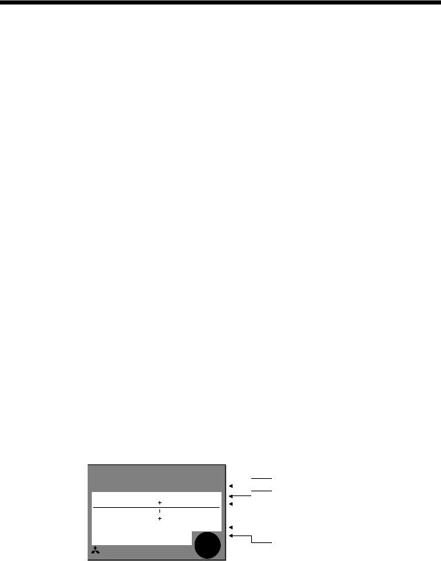
1. FUNCTIONS AND CONFIGURATION
Function |
Description |
(Note) |
Refer to |
|
Control mode |
||||
|
|
|
||
Alarm history clear |
Alarm history is cleared. |
P, S, T |
Parameter No. 16 |
|
Restart after instantaneous |
If the input power supply voltage had reduced to cause an |
|
|
|
alarm but has returned to normal, the servo motor can be |
S |
Parameter No. 20 |
||
power failure |
restarted by merely switching on the start signal. |
|
|
|
|
|
|
||
Command pulse selection |
Command pulse train form can be selected from among four |
P |
Parameter No. 21 |
|
different types. |
||||
|
|
|
||
Input signal selection |
Forward rotation start, reverse rotation start, servo-on and |
P, S, T |
Parameters |
|
other input signals can be assigned to any pins. |
No. 43 to 48 |
|||
|
|
|||
Torque limit |
Servo motor-generated torque can be limited to any value. |
P, S |
Section 3.4.1 (5) |
|
Parameter No. 28 |
||||
|
|
|
||
|
|
|
Section 3.4.3 (3) |
|
Speed limit |
Servo motor speed can be limited to any value. |
T |
Parameter No. 8 |
|
|
|
|
to 10,72 to 75 |
|
Status display |
Servo status is shown on the 5-digit, 7-segment LED |
P, S, T |
Section 6.2 |
|
display |
||||
|
|
|
||
External I/O display |
ON/OFF statuses of external I/O signals are shown on the |
P, S, T |
Section 6.6 |
|
display. |
||||
|
|
|
||
|
Output signal can be forced on/off independently of the |
|
|
|
Output signal forced output |
servo status. |
P, S, T |
Section 6.7 |
|
|
Use this function for output signal wiring check, etc. |
|
|
|
|
Voltage is automatically offset to stop the servo motor if it |
|
|
|
Automatic VC offset |
does not come to a stop at the analog speed command (VC) |
S, T |
Section 6.3 |
|
|
or analog speed limit (VLA) of 0V. |
|
|
|
Test operation mode |
Servo motor can be run from the operation section of the |
P, S, T |
Section 6.8 |
|
servo amplifier without the start signal entered. |
||||
|
|
|
||
Analog monitor output |
Servo status is output in terms of voltage in real time. |
P, S, T |
Parameter No. 17 |
|
Servo configuration software |
Using a personal computer, parameter setting, test |
P, S, T |
Section 13.1.6 |
|
operation, status display, etc. can be performed. |
||||
Alarm code output |
If an alarm has occurred, the corresponding alarm number |
P, S, T |
Section 10.2.1 |
|
is output in 3-bit code. |
||||
|
|
|
||
Note:P: Position control mode, S: Speed control mode, T: Torque control mode |
|
|
||
P/S: Position/speed control change mode, S/T: Speed/torque control change mode, T/P: Torque/position control change mode
1.5 Model code definition
(1) Rating plate
MITSUBISHI |
|
|
AC SERVO |
|
|
|
Model |
||||||
|
|
|
|
|
|
|
|
AC SERVO |
|
|
|
|
|
MODEL |
|
|
MR-J2S-60A |
|
|
|
|
|
Capacity |
||||
|
|
|
|
|
|
|
|
|
|
||||
|
|
|
|
|
|
|
|
|
|
|
|
|
|
|
|
POWER : 600W |
|
|
|||||||||
|
|
|
|
|
|
|
|
||||||
|
POWERINPUT |
|
|
: 3.2A 3PH 1PH200-230V 50Hz |
|
|
|
Applicable power supply |
|||||
|
|
|
|
|
|
||||||||
|
|
|
|
|
3PH 1PH200-230V 60Hz |
|
|
|
|
||||
|
|
|
|
|
5.5A 1PH 230V 50/60Hz |
|
|
|
|
|
|||
|
|
OUTPUT : 170V 0-360Hz 3.6A |
|
|
|
|
Rated output current |
||||||
|
|
|
|
||||||||||
|
|
SERIAL |
: TC3XXAAAAG52 |
|
|
|
|
||||||
|
|
|
|
|
|
Serial number |
|
|
|
|
|
PASSED |
|
|
|
|
|
|
|
|
|
MITSUBISHI ELECTRIC CORPORATION |
|
|
|
|
|
|
MADE IN JAPAN |
|
|
|
|
|
1 - 5
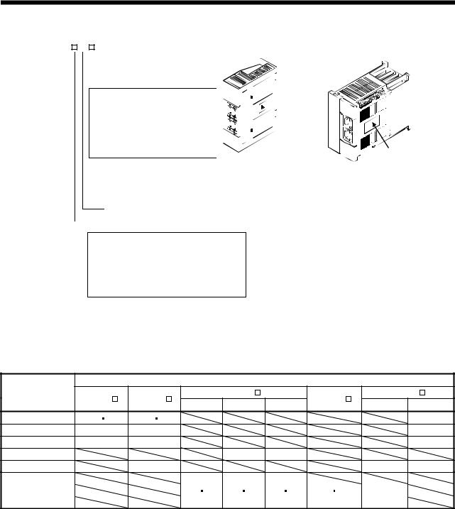
1. FUNCTIONS AND CONFIGURATION
(2) Model
MR–J2S– A |
|
MR–J2S–100A or less |
||||||||||||||||||||||||||
|
|
|
|
|
|
|
|
|
|
|
|
|
|
|
|
|
|
|
|
|
|
|
|
|
|
|
|
|
|
|
|
|
|
|
|
|
|
|
|
|
|
|
|
|
|
|
|
|
|
|
|
|
|
|
|
|
|
|
|
|
|
|
|
|
|
|
|
|
|
|
|
|
|
|
|
|
|
|
|
|
|
|
|
|
|
|
Series |
|
|
Power Supply |
|
|
|
|
|
|
|
|
|
|
|
|
|
|
|
|
|
||||||||
|
|
|
|
|
|
|
|
|
|
|
|
|
|
|
|
|
||||||||||||
|
|
|
|
|
|
|
|
Symbol |
|
Power supply |
|
|
|
|
|
|
|
|
|
|
|
|
|
|
|
|
|
|
|
|
|
|
|
|
|
|
|
|
|
|
|
|
|
|
|
|
|
|
|
|
|
|
|
|
|||
|
|
|
|
|
|
|
|
|
|
|
|
|
|
|
|
|
|
|
|
|
|
|
|
|
|
|||
|
|
|
|
|
|
|
|
None |
|
3-phase 200 to230V |
|
|
|
|
|
|
|
|
|
|
|
|
|
|
|
|
|
|
|
|
|
|
|
|
|
|
|
|
|
|
|
|
|
|
|
|
|
|
|
|
|
|
|
|
|||
|
|
|
|
|
|
|
|
|
|
|
(Note2) 1-phase 230V |
|
|
|
|
|
|
|
|
|
|
|
|
|
|
|
|
|
|
|
|
|
|
|
|
|
(Note1) |
|
1-phase 100V to 120V |
|
|
|
|
|
|
|
|
|
|
|
|
Rating plate |
|||||
|
|
|
|
|
|
|
|
|
|
|
|
|
|
|
|
|
|
|
|
|
||||||||
1 |
|
|
|
|
|
|
|
|
|
|
|
|
|
|||||||||||||||
|
|
|
|
|
|
|
|
|
|
|
|
|
|
|
|
|
|
|
||||||||||
|
|
|
|
|
|
|
|
|
|
|
|
|
|
|
|
|
|
|
|
|
|
|
|
|
|
|
|
|
Note:1. Not supplied to the servo amplifier of MR-J2S-60A or more. 2. Not supplied to the servo amplifier of MR-J2S-100A or more.
General-purpose interface
Rated output |
|
|
|
|
|
|
|
|
Symbol |
|
Rated |
|
Symbol |
|
Rated |
|
|
|
|
||||
|
|
|
output [W] |
|
|
|
output [W] |
|
10 |
|
100 |
|
70 |
|
700 |
|
20 |
|
200 |
|
100 |
|
1000 |
|
40 |
|
400 |
|
200 |
|
2000 |
60 |
|
600 |
|
350 |
|
3500 |
|
|
|
|
|
|
|
|
|
MR–J2S–200A 350A
350A


 Rating plate
1.6 Combination with servo motor
The following table lists combinations of servo amplifiers and servo motors. The same combinations apply to the models with electromagnetic brakes and the models with reduction gears.
Servo motors
Servo amplifier |
HC-KFS |
HC-MFS |
HC-SFS |
|
HC-UFS |
|||
|
2000r/min |
3000r/min |
HC-RFS |
3000r/min |
||||
|
|
|
|
1000r/min |
2000r/min |
|||
MR-J2S-10A(1) |
053 |
13 |
053 |
13 |
|
|
|
13 |
MR-J2S-20A(1) |
23 |
|
23 |
|
|
|
|
23 |
MR-J2S-40A(1) |
43 |
|
43 |
|
|
|
|
43 |
MR-J2S-60A |
|
|
|
|
52 |
53 |
|
|
MR-J2S-70A |
|
|
73 |
|
|
|
72 |
73 |
MR-J2S-100A |
81 |
102 |
103 |
|
|
MR-J2S-200A |
121 201 |
152 202 |
153 203 |
103 153 |
152 |
MR-J2S-350A |
301 |
352 |
353 |
203 |
202 |
1 - 6
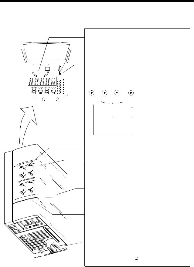
1. FUNCTIONS AND CONFIGURATION
1.7 Parts identification
(1) MR-J2S-100A or less
|
|
|
|
|
|
|
|
|
|
|
|
|
|
|
|
|
|
|
|
|
Name/Application |
|
Refer to |
||||||
|
|
|
|
|
|
|
|
|
|
|
|
|
|
|
|
|
|
|
|
|
|
|
|
|
|
|
|
|
|
|
|
|
|
|
|
|
|
|
|
|
|
|
|
|
|
|
|
|
|
Battery holder |
|
|
|
|
|
Section15.3 |
|||
|
|
|
|
|
|
|
|
|
|
|
|
|
|
|
|
|
|
|
|
Contains the battery for absolute position data backup. |
|||||||||
|
|
|
|
|
|
|
|
|
|
|
|
|
|
|
|
|
|
|
|
|
|
|
|||||||
|
|
|
|
|
|
|
|
|
|
|
|
|
|
|
|
|
|
|
|
|
|
|
|
|
|
|
|
|
|
|
|
|
|
|
|
|
|
|
|
|
|
|
|
|
|
|
|
|
|
Battery connector (CON1) |
|
|
|
|
|
Section15.3 |
|||
|
|
|
|
|
|
|
|
|
|
|
|
|
|
|
|
|
|
|
|
|
|
|
|
|
|||||
|
|
|
|
|
|
|
|
|
|
|
|
|
|
|
|
|
|
|
|
Used to connect the battery for absolute position data |
|||||||||
|
|
|
|
|
|
|
|
|
|
|
|
|
|
|
|
|
|
|
|
backup. |
|
|
|
|
|
|
|
|
|
|
|
|
|
|
|
|
|
|
|
|
|
|
|
|
|
|
|
|
|
|
|
|
|
|
|
|
|
|
|
|
|
|
|
|
|
|
|
|
|
|
|
|
|
|
|
|
|
|
|
Display |
|
|
|
|
|
|
|
Chapter6 |
|
|
|
|
|
|
|
|
|
|
|
|
|
|
|
|
|
|
|
|
|
The 5-digit, seven-segment LED shows the servo |
|
||||||||
|
|
|
|
|
|
|
|
|
|
|
|
|
|
|
|
|
|
|
|
|
|||||||||
|
|
|
|
|
|
|
|
|
|
|
|
|
|
|
|
|
|
|
|
status and alarm number. |
|
|
|
|
|
|
|
|
|
|
|
|
|
|
|
|
|
|
|
|
|
|
|
|
|
|
|
|
|
|
|
|
|
|
|
|
|
||
|
|
|
|
|
|
|
|
|
|
|
|
|
|
|
|
|
|
|
|
|
|
|
|
|
|
|
|
|
|
|
|
|
|
|
|
|
|
|
|
|
|
|
|
|
|
|
|
|
|
Operation section |
|
|
|
|
|
|
|
|
|
|
|
|
|
|
|
|
|
|
|
|
|
|
|
|
|
|
|
|
|
|
|
|
|
|
|
|
|
||
|
|
|
|
|
|
|
|
|
|
|
|
|
|
|
|
|
|
|
|
Used to perform status display, diagnostic, alarm and |
|
|
|
||||||
|
|
|
|
|
|
|
|
|
|
|
|
|
|
|
|
|
|
|
|
|
|
|
|||||||
|
|
|
|
|
|
|
|
|
|
|
|
|
|
|
|
|
|
|
|
parameter setting operations. |
|
|
|
||||||
|
|
|
|
|
|
|
|
|
|
|
|
|
|
|
|
|
|
|
|
MODE |
UP DOWN |
SET |
|
Chapter6 |
|||||
|
|
|
|
|
|
|
|
|
|
|
|
|
|
|
|
|
|
|
|
|
|
Used to set data. |
|
||||||
|
|
|
|
|
|
|
|
|
|
|
|
|
|
|
|
|
|
|
|
|
|
|
|||||||
|
|
|
|
|
|
|
|
|
|
|
|
|
|
|
|
|
|
|
|
|
|
|
|||||||
|
|
|
|
|
|
|
|
|
|
|
|
|
|
|
|
|
|
|
|
|
|
Used to change the |
|
|
|
||||
|
|
|
|
|
|
|
|
|
|
|
|
|
|
|
|
|
|
|
|
|
|
display or data in each |
|
|
|
||||
|
|
|
|
|
|
|
|
|
|
|
|
|
|
|
|
|
|
|
|
|
|
mode. |
|
|
|
||||
|
|
|
|
|
|
|
|
|
|
|
|
|
|
|
|
|
|
|
|
|
|
Used to change the |
|
|
|
||||
|
|
|
|
|
|
|
|
|
|
|
|
|
|
|
|
|
|
|
|
|
|
mode. |
|
|
|
||||
|
|
|
|
|
|
|
|
|
|
|
|
|
|
|
|
|
|
|
|
|
|
|
|
|
|
|
|
||
|
|
|
|
|
|
|
|
|
|
|
|
|
|
|
|
|
|
|
|
I/O signal connector (CN1A) |
|
Section3.3 |
|||||||
|
|
|
|
|
|
|
|
|
|
|
|
|
|
|
|
|
|
|
|
Used to connect digital I/O signals. |
|
||||||||
|
|
|
|
|
|
|
|
|
|
|
|
|
|
|
|
|
|
|
|
I/O signal connector (CN1B) |
|
Section3.3 |
|||||||
|
|
|
|
|
|
|
|
|
|
|
|
|
|
|
|
|
|
|
|
Used to connect digital I/O signals. |
|
|
|
||||||
|
|
|
|
|
|
|
|
|
|
|
|
|
|
|
|
|
|
|
|
Communication connector (CN3) |
Chapter14 |
||||||||
|
|
|
|
|
|
|
|
|
|
|
|
|
|
|
|
|
|
|
|
Used to connect a command device (RS-422/RS-232C) |
Section13.1.2 |
||||||||
|
|
|
|
|
|
|
|
|
|
|
|
|
|
|
|
|
|
|
|
and output analog monitor data. |
|
|
|
||||||
|
|
|
|
|
|
|
|
|
|
|
|
|
|
|
|
|
|
|
|
Name plate |
|
|
|
|
|
|
Section1.5 |
||
|
|
|
|
|
|
|
|
|
|
|
|
|
|
|
|
|
|
|
|
|
|
|
|
|
|
|
|
|
|
|
|
|
|
|
|
|
|
|
|
|
|
|
|
|
|
|
|
|
|
|
|
|
|
|
|
|
|
|
|
|
|
|
|
|
|
|
|
|
|
|
|
|
|
|
|
|
|
|
|
Charge lamp |
|
|
|
|
|
|
|
|
|
|
|
|
|
|
|
|
|
|
|
|
|
|
|
|
|
|
|
|
|
|
|
|
|
|
|
|
|
||
|
|
|
|
|
|
|
|
|
|
|
|
|
|
|
|
|
|
|
|
|
|
|
|
|
|
|
|
||
|
|
|
|
|
|
|
|
|
|
|
|
|
|
|
|
|
|
|
|
Lit to indicate that the main circuit is charged. While |
|
|
|
||||||
|
|
|
|
|
|
|
|
|
|
|
|
|
|
|
|
|
|
|
|
this lamp is lit, do not reconnect the cables. |
|
|
|
||||||
|
|
|
|
|
|
|
|
|
|
|
|
|
|
|
|
|
|
|
|
Encoder connector (CN2) |
|
|
|
|
|
|
Section3.3 |
||
|
|
|
|
|
|
|
|
|
|
|
|
|
|
|
|
|
|
|
|
Connector for connection of the servo motor encoder. |
Section13.1.2 |
||||||||
|
|
|
|
|
|
|
|
|
|
|
|
|
|
|
|
|
|
|
|
|
|
|
|
|
|
|
|
||
|
|
|
|
|
|
|
|
|
|
|
|
|
|
|
|
|
|
|
|
Main circuit terminal block (TE1) |
|
Section3.7 |
|||||||
|
|
|
|
|
|
|
|
|
|
|
|
|
|
|
|
|
|
|
|
Used to connect the input power supply and servo |
|
||||||||
|
|
|
|
|
|
|
|
|
|
|
|
|
|
|
|
|
|
|
|
motor. |
|
|
|
|
|
|
|
|
|
|
|
|
|
|
|
|
|
|
|
|
|
|
|
|
|
|
|
|
|
Control circuit terminal block (TE2) |
|
Section3.7 |
|||||||
|
|
|
|
|
|
|
|
|
|
|
|
|
|
|
|
|
|
|
|
|
|||||||||
|
|
|
|
|
|
|
|
|
|
|
|
|
|
|
|
|
|
|
|
Used to connect the control circuit power supply and |
|
||||||||
|
|
|
|
|
|
|
|
|
|
|
|
|
|
|
|
|
|
|
|
Section13.1.1 |
|||||||||
|
|
|
|
|
|
|
|
|
|
|
|
|
|
|
|
|
|
|
|
regenerative brake option. |
|
|
|
|
|
||||
|
|
|
|
|
|
|
|
|
|
|
|
|
|
|
|
|
|
|
|
|
|
|
|
|
|||||
|
|
|
|
|
|
|
|
|
|
|
|
|
|
|
|
|
|
|
|
|
|
|
|
|
|
|
|
||
|
|
|
|
|
|
|
|
|
|
|
|
|
|
|
|
|
|
|
|
|
|
|
|
|
|
|
|
|
|
|
|
|
|
|
|
|
|
|
|
|
|
|
|
|
|
|
|
|
|
Protective earth (PE) terminal ( |
|
|
|
) |
Section3.10 |
||||
|
|
|
|
|
|
|
|
|
|
|
|
|
|
|
|
|
|
|
|
|
|
|
|||||||
|
|
|
|
|
|
|
|
|
|
|
|
|
|
|
|
|
|
|
|
Ground terminal. |
|
|
|
|
|
||||
|
|
|
|
|
|
|
|
|
|
|
|
|
|
|
|
|
|
|
|
|
|
|
|
|
|
|
|
||
|
|
|
|
|
|
|
|
|
|
|
|
|
|
|
|
|
|
|
|
|
|
|
|
|
|
|
|
|
|
1 - 7
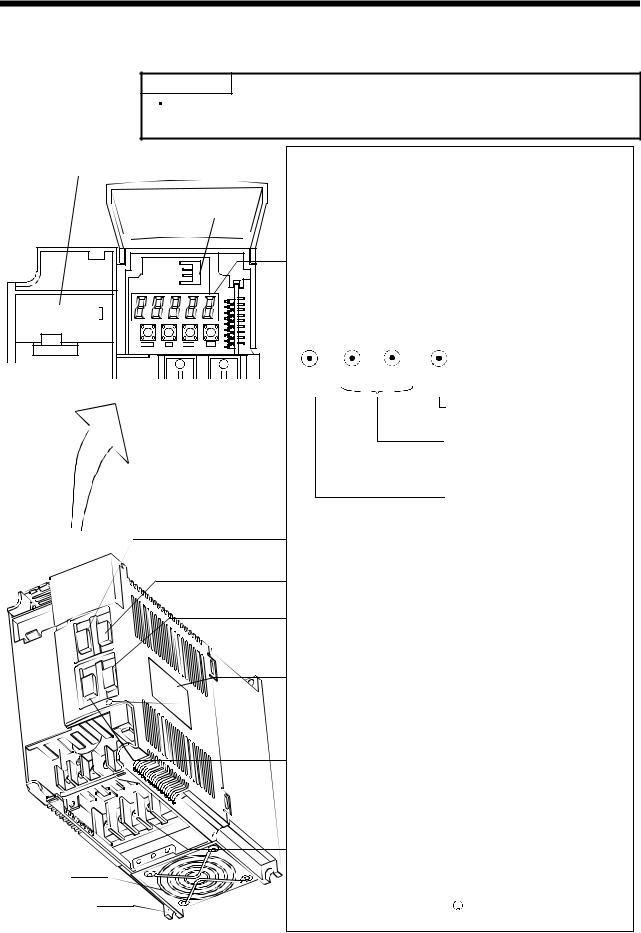
1. FUNCTIONS AND CONFIGURATION
(2) MR-J2S-200A or more
POINT
The servo amplifier is shown without the front cover. For removal of the front cover, refer to next page.
Cooling fan
Installation notch (4 places)
|
Name/Application |
|
Refer to |
|||||||
|
|
|
|
|
|
|
|
|
||
Battery holder |
|
|
|
|
|
Section15.3 |
||||
Contains the battery for absolute position data backup. |
||||||||||
|
|
|
||||||||
|
|
|
|
|
|
|
|
|
||
Battery connector (CON1) |
|
|
|
|
|
Section15.3 |
||||
Used to connect the battery for absolute position data |
||||||||||
backup. |
|
|
|
|
|
|
|
|
|
|
|
|
|
|
|
|
|
|
|
|
|
Display |
|
|
|
|
|
|
|
Chapter6 |
||
The 5-digit, seven-segment LED shows the servo |
|
|||||||||
status and alarm number. |
|
|
|
|
|
|
|
|
||
|
|
|
|
|
|
|
|
|
||
Operation section |
|
|
|
|
|
|
|
|
||
Used to perform status display, diagnostic, alarm and |
|
|
|
|||||||
parameter setting operations. |
|
|
|
|||||||
MODE |
UP DOWN |
SET |
|
|
|
|||||
|
|
Used to set data. |
|
Chapter6 |
||||||
|
|
Used to change the |
|
|
|
|||||
|
|
display or data in each |
|
|
|
|||||
|
|
mode. |
|
|
|
|||||
|
|
Used to change the |
|
|
|
|||||
|
|
mode. |
|
|
|
|||||
|
|
|
|
|
|
|
|
|||
I/O signal connector (CN1A) |
|
Section3.3 |
||||||||
Used to connect digital I/O signals. |
|
|||||||||
|
|
|
||||||||
|
|
|
|
|
|
|
|
|||
I/O signal connector (CN1B) |
|
Section3.3 |
||||||||
Used to connect digital I/O signals. |
|
|||||||||
|
|
|
||||||||
|
|
|
|
|
|
|
|
|||
Communication connector (CN3) |
Chapter14 |
|||||||||
Used to connect a command device (RS-422/RS232C) |
||||||||||
Section13.1.2 |
||||||||||
and output analog monitor data. |
|
|
|
|||||||
|
|
|
|
|
|
|
|
|||
Name plate |
|
|
|
|
|
|
Section1.5 |
|||
|
|
|
|
|
|
|
|
|
||
Charge lamp |
|
|
|
|
|
|
|
|
||
Lit to indicate that the main circuit is charged. While |
|
|
|
|||||||
|
|
|
||||||||
this lamp is lit, do not reconnect the cables. |
|
|
|
|||||||
|
|
|
|
|
|
|
|
|||
Encoder connector (CN2) |
|
|
|
|
|
|
Section3.3 |
|||
Connector for connection of the servo motor encoder. |
Section13.1.2 |
|||||||||
|
|
|
|
|
|
|
|
|||
Main circuit terminal block (TE1) |
|
Section3.7 |
||||||||
Used to connect the input power supply and servo |
|
|||||||||
motor. |
|
|
|
|
|
|
|
|
|
|
|
|
|
|
|
|
|
|
|||
Control circuit terminal block (TE2) |
|
Section3.7 |
||||||||
Used to connect the control circuit power supply and |
|
|||||||||
Section13.1.1 |
||||||||||
regenerative brake option. |
|
|
|
|
|
|
|
|
||
|
|
|
|
|
|
|
|
|||
Protective earth (PE) terminal ( |
|
|
|
) |
Section3.10 |
|||||
|
|
|
||||||||
Ground terminal. |
|
|
|
|
|
|||||
|
|
|
|
|
|
|
|
|||
|
|
|
|
|
|
|
|
|
|
|
1 - 8
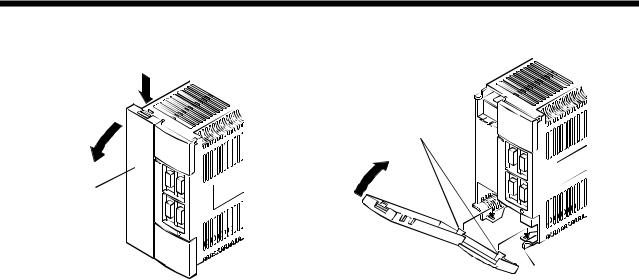
1. FUNCTIONS AND CONFIGURATION
Removal of the front cover 1)
2)
Front cover
1)Hold down the removing knob.
2)Pull the front cover toward you.
Reinstallation of the front cover
Front cover hook (2 places)
2)
1)
Front cover socket (2 places)
1)Insert the front cover hooks into the front cover sockets of the servo amplifier.
2)Press the front cover against the servo amplifier until the removing knob clicks.
1 - 9

1. FUNCTIONS AND CONFIGURATION
1.8 Servo system with auxiliary equipment
To prevent an electric shock, always connect the protective earth (PE) terminal WARNING (terminal marked  ) of the servo amplifier to the protective earth (PE) of the control
box.
(1) MR-J2S-100A or less
(a) For 3-phase 200V to 230VAC or 1-phase 230VAC
(Note2) |
|
|
|
|
|
|
|
|
3-phase 200V |
|
Options and auxiliary equipment |
Refer to |
Options and auxiliary equipment |
Refer to |
|||
to 230VAC power |
|
|||||||
|
|
|
|
|
|
|
|
|
supply or |
|
No-fuse breaker |
|
|
Section 13.2.2 |
Regenerative brake option |
Section 13.1.1 |
|
1-phase 230VAC |
|
Magnetic contactor |
|
Section 13.2.2 |
Cables |
|
Section 13.2.1 |
|
power supply |
|
|
|
|||||
|
|
|
|
|
|
|
|
|
|
|
Servo configuration software |
Section 13.1.6 |
|
|
|
||
No-fuse breaker |
|
|
|
|
|
|
|
|
(NFB) or fuse |
|
|
|
|
|
|
|
|
|
|
Servo amplifier |
|
|
|
|
||
|
|
|
|
|
|
Command device |
|
|
|
|
|
|
|
To CN1A |
|
|
|
Magnetic |
|
|
|
|
|
|
Junction terminal block |
|
|
|
|
|
|
|
|
|
|
contactor |
|
|
|
|
|
|
|
|
(MC) |
|
|
|
|
To CN1B |
|
|
|
|
|
|
|
|
|
|
|
|
|
|
|
CHARGE |
To CN3 |
|
|
|
|
|
|
|
|
Personal |
Servo configuration |
|||
|
|
|
|
|
|
|||
|
|
|
|
|
|
computer |
software |
|
|
To CN2 |
|
|
|
|
MRZJW3-SETUP121E |
||
|
L1 |
|
|
|
|
|
|
|
|
L2 |
U |
V |
W |
|
|
|
|
|
L3 |
|
|
|
|
|||
|
|
|
|
|
|
|
|
|
|
|
|
|
Protective earth(PE) terminal |
|
|
||
|
|
|
|
|
|
(Note1) |
|
|
|
|
|
|
|
|
Encoder cable |
|
|
(Note1)
Power supply lead
Control circuit terminal block |
|
|
|
|
|
|
|
|
D |
|
|
|
|
|
|
|
|
|
||
|
|
|
|
|
|
|
|
|
|
|
|
|
|
|||||||
|
|
|
|
|
|
|
|
|
|
|
|
|
|
|
|
|
|
|
|
|
L21
L11
|
|
|
|
|
|
|
|
|
|
|
|
|
|
|
|
|
|
|
|
|
|
|
|
Regenerative brake |
P |
|
|
||||
|
|
|
|
|
|
Servo motor |
|
|
|
|
|
|
|
||
option |
|
|
|
|
|
|
|
|
|
|
|
|
|
|
|
C |
|
|
|
|
|
|
|
|
|
|
|
|
|
||
Note: 1. The HC-SFS, HC-RFS series have cannon connectors.
2.A 1-phase 230V power supply may be used with the servo amplifier of MR-J2S-70A or less. Connect the power supply to L1 and L2 terminals and leave L3 open.
1 - 10
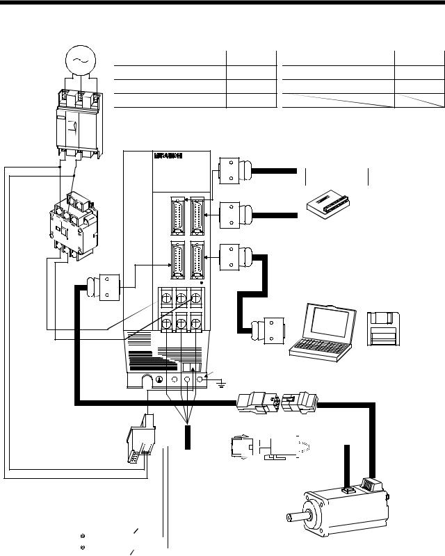
1. FUNCTIONS AND CONFIGURATION |
|
|
|
|
||||
(b) For 1-phase 100V to 120VAC |
|
|
|
|
|
|
||
1-phase 100V |
|
|
|
|
|
|
|
|
to 120VAC |
|
Options and auxiliary equipment |
Refer to |
Options and auxiliary equipment |
Refer to |
|||
power supply |
|
No-fuse breaker |
|
Section 13.2.2 |
Regenerative brake option |
Section 13.1.1 |
||
|
|
|
||||||
|
|
Magnetic contactor |
|
Section 13.2.2 |
Cables |
|
Section 13.2.1 |
|
|
|
Servo configuration software |
Section 13.1.6 |
|
|
|
||
No-fuse breaker |
|
|
|
|
|
|
|
|
(NFB) or fuse |
|
|
|
|
|
|
|
|
|
|
Servo amplifier |
|
|
|
|
||
|
|
|
|
|
|
Command device |
|
|
|
|
|
|
|
To CN1A |
|
|
|
Magnetic |
|
|
|
|
|
Junction terminal block |
||
|
|
|
|
|
|
|
|
|
contactor |
|
|
|
|
|
|
|
|
(MC) |
|
|
|
|
To CN1B |
|
|
|
|
|
|
|
|
|
|
|
|
|
|
|
CHARGE |
To CN3 |
|
|
|
|
|
|
|
|
Personal |
Servo configuration |
|||
|
|
|
|
|
|
|||
|
|
|
|
|
|
computer |
software |
|
|
To CN2 |
|
|
|
|
|
MRZJW3-SETUP121E |
|
|
L1 |
|
|
|
|
|
|
|
|
L2 |
U |
V |
W |
|
|
|
|
|
|
|
|
|
|
|||
|
|
|
|
Protective earth(PE) terminal |
|
|
||
|
|
|
|
|
|
(Note) |
|
|
|
|
|
|
|
|
Encoder cable |
|
|
|
|
|
|
|
|
(Note) |
|
|
|
|
|
|
|
|
Power supply lead |
|
|
Control circuit terminal block |
|
|
|
|
|
|
|
D |
|
|
|
|
|
|
|
|
|
||
|
|
|
|
|
|
|
|
|
|
|
|
|
|
|
|
|
|
|
|
L21
L11
|
|
|
|
|
|
|
|
|
|
|
|
|
|
|
|
|
|
|
|
|
|
|
|
Regenerative brake |
P |
|
|
||||
|
|
|
|
|
|
Servo motor |
|
|
|
|
|
|
|
||
option |
|
|
|
|
|
|
|
C |
|
|
|
|
|
|
|
|
|
|
|
|
|
||
Note: The HC-SFS, HC-RFS series have cannon connectors.
1 - 11
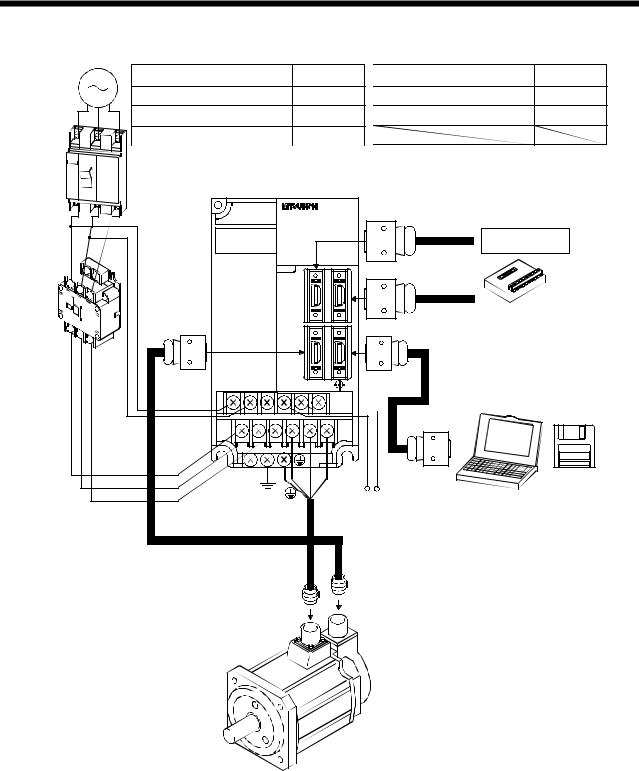
1. FUNCTIONS AND CONFIGURATION
(2) MR-J2S-200A or more |
|
|
|
|
3-phase 200V |
Options and auxiliary equipment |
Refer to |
Options and auxiliary equipment |
Refer to |
|
|
|
|
|
to 230VAC |
No-fuse breaker |
Section 13.2.2 Regenerative brake option |
Section 13.1.1 |
|
power supply |
Magnetic contactor |
Section 13.2.2 |
Cables |
Section 13.2.1 |
|
||||
|
Servo configuration software |
Section 13.1.6 |
|
|
No-fuse |
|
|
breaker |
|
|
(NFB) or |
Servo amplifier |
|
fuse |
||
|
|
|
|
|
|
Command device |
|
|
|
|
|
|
To CN1A |
Junction terminal |
Magnetic |
|
|
|
|
|
|
|
|
|
|
|
block |
|
contactor |
|
|
|
|
|
|
(MC) |
|
|
|
|
|
|
|
|
|
|
|
To CN1B |
|
To CN2 |
|
|
|
|
To CN3 |
Servo |
|
|
|
|
configuration |
||
|
|
|
|
|
Personal |
software |
L11 |
|
|
|
|
computer |
MRZJW3- |
L21 |
|
|
|
|
|
SETUP121E |
|
|
|
|
|
|
|
L1 |
U |
V |
W |
P |
C |
|
L2 |
|
|||||
|
|
|
|
|
|
|
L3 |
|
|
|
Regenerative brake option |
|
|
|
|
|
|
|
||
1 - 12
2.INSTALLATION
2.INSTALLATION
Stacking in excess of the limited number of products is not allowed. Install the equipment to incombustibles. Installing them directly or close to combustibles will led to a fire.
Install the equipment in a load-bearing place in accordance with this Instruction Manual.
Do not get on or put heavy load on the equipment to prevent injury. Use the equipment within the specified environmental condition range.
Provide an adequate protection to prevent screws, metallic detritus and other CAUTION conductive matter or oil and other combustible matter from entering the servo
amplifier.
Do not block the intake/exhaust ports of the servo amplifier. Otherwise, a fault may occur.
Do not subject the servo amplifier to drop impact or shock loads as they are precision equipment.
Do not install or operate a faulty servo amplifier.
When the product has been stored for an extended period of time, consult Mitsubishi.
2.1 Environmental conditions
Environment |
|
|
|
|
|
Conditions |
|
Ambient temperature |
0 to |
55 [ ] (non-freezing) |
|||||
32 to |
131 [ |
] (non-freezing) |
|||||
|
|||||||
Ambient humidity |
90%RH or less (non-condensing) |
||||||
Storage temperature |
|
|
20 to |
65 [ |
] (non-freezing) |
||
|
|
||||||
|
|
4 to |
149 [ |
] (non-freezing) |
|||
|
|
|
|||||
|
|
|
|||||
Storage humidity |
90%RH or less (non-condensing) |
||||||
Ambient |
Indoors (no direct sunlight) |
||||||
Free from corrosive gas, flammable gas, oil mist, dust and dirt |
|||||||
|
|||||||
Altitude |
Max. 1000m (3280 ft) above sea level |
||||||
Vibration |
5.9 [m/s2] or less |
||||||
19.4 [ft/s2] or less |
|||||||
|
|||||||
2 - 1
Loading...