


Q25HCPU
Table of contents
 Loading...
C
MIT
SUBIS
C
HI ELECTRI
MELSEC System Q
Programmable Logic Controllers
User’s Manual
High Performance Model QCPU
Art. no.: 130000
01 10 2002
SH (NA)-080037-F
Q02CPU, Q02HCPU,
Q06HCPU, Q12HCPU,
Q25HCPU
MITSUBISHI ELECTRI
INDUSTRIAL AUTOMATION
SAFETY PRECAUTIONS
(Read these precautions before using.)
When using Mitsubishi equipment, thoroughly read this manual and the associated manuals introduced in
this manual. Also pay careful attention to safety and handle the module properly .
These SAFETY PRECAUTIONS classify the safety precautions int o two cat egories: "DANG ER" and
"CAUTION".
DANGER
!
CAUTION
!
Depending on circumstances, procedures indicated by ! CAUTION may also be linked to serious
results.
In any case, it is important to follow the directions for usage.
Store this manual in a safe place so that you can take it out and read it whenever necessary . Alw ay s
forward it to the end user.
Indicates that incorrect handling may cause hazardous conditions,
resulting in death or severe injury.
Indicates that incorrect handling may cause hazardous conditions,
resulting in medium or slight personal injury or physical damage.
[DESIGN PRECAUTIONS]
!
DANGER
Install a safety circuit external to the PLC that keeps the ent ire syst em safe even when t here
are problems with the external power supply or the PLC module. Otherwise, t rouble could result
from erroneous output or erroneous operation.
(1) Outside the PLC, construct mechanical damage preventing interlock circuits such as
emergency stop, protective circuits, positioning upper and low er limits switches and
interlocking forward/reverse operations.
(2) When the PLC detects the following problems, it will stop calculation and turn off all out put
in the case of (a). In the case of (b), it will st op calculation and hold or t urn off all out put
according to the parameter setting.
Note that the AnS series module will turn off the out put in eit her of cases (a) and (b).
(a) The power supply module has over current protection equipment and over voltage
protection equipment.
(b) The PLC CPUs self-diagnosis functions, such as the watch dog timer error, detect
problems.
In addition, all output will be turned on when t here are pr oblems that t he PLC CPU cannot
detect, such as in the I/O controller. Build a fail safe circuit exterior to the PLC that will make
sure the equipment operates safely at such times. See section 9.1 of this manual for
example fail safe circuits.
(3) Output could be left on or off when there is trouble in the outputs module relay or transist or.
So build an external monitoring circuit that will monit or any single output s that could cause
serious trouble.
A - 1 A - 1
[DESIGN PRECAUTIONS]
!
DANGER
When overcurrent which exceeds the rating or caused by short-circuited load flows in the output
module for a long time, it may cause smoke or fire. To prevent this, configure an external safety
circuit, such as fuse.
Build a circuit that turns on the external power supply w hen the PLC main module power is
turned on. If the external power supply is turned on first, it could result in erroneous out put or
erroneous operation.
When there are communication problems with the data link, refer to the corresponding data link
manual for the operating status of each station. Not doing so could result in erroneous output or
erroneous operation.
When connecting a peripheral device to the CPU module or connecting a personal computer or
the like to the intelligent function module to exercise control (data change) on the running PLC,
configure up an interlock circuit in the sequence program to ensure that t he whole sy stem w ill
always operate safely.
Also before exercising other control (program change, operating status change (status control))
on the running PLC, read the manual carefully and fully confirm safety.
Especially for the above control on the remote PLC from an external device, an immediate
action may not be taken for PLC trouble due to a data communication fault.
In addition to configuring up the interlock circuit in the sequence program, corrective and other
actions to be taken as a system for the occurrence of a data communication fault should be
predetermined between the external device and PLC CPU.
!
CAUTION
Do not bunch the control wires or communication cables with the main circuit or power wires, or
install them close to each other. They should be installed 100 mm (3.94 inch) or more from
each other. Not doing so could result in noise that would cause erroneous operation.
When controlling items like lamp load, heater or solenoid valve using an output module, large
current (approximately ten times greater than that present in normal circumstances) may flow
when the output is turned OFF to ON.
Take measures such as replacing the module with one having sufficient rated current.
A - 2 A - 2
[INSTALLATION PRECAUTIONS]
!
CAUTION
Use the PLC in an environment that meets the general specifications contained in this manual.
Using this PLC in an environment outside the range of the general specifications could result in
electric shock, fire, erroneous operation, and damage to or deterioration of the product.
Hold down the module loading lever at the module bottom, and securely insert the module
fixing latch into the fixing hole in the base unit.
Incorrect loading of the module can cause a malfunction, failure or drop.
When using the PLC in the environment of much vibration, tighten the module with a screw.
Tighten the screw in the specified torque range. Undertightening can cause a drop, short circuit
or malfunction. Overtightening can cause a drop, short circuit or malfunction due to damage to
the screw or module.
When installing extension cables, be sure that the connectors of base unit are installed
correctly. After installation, check them for looseness. Poor connections could cause an input or
output failure.
Securely load the memory card into the memory card loading connector. After loading, check
for lifting. Lifting can cause a malfunction due to a contact fault.
Completely turn off the external power supply before loading or unloading the module. Not
doing so could result in electric shock or damage to the product.
Do not directly touch the module's conductive parts or electronic components. Touching the
conductive parts could cause an operation failure or give damage to the module.
[WIRING PRECAUTIONS]
!
DANGER
Completely turn off the external pow er supply when inst alling or placing w iring. Not completely
turning off all power could result in electric shock or damage to the product.
When turning on the power supply or operating the module after installation or wiring work, be
sure that the module's terminal covers are correctly attached. Not at taching the t erminal cover
could result in electric shock.
A - 3 A - 3
[WIRING PRECAUTIONS]
!
CAUTION
Be sure to ground the FG terminals and LG terminals to the protective ground conductor. Not
doing so could result in electric shock or erroneous operation.
When wiring in the PLC, be sure that it is done correctly by checking the product's rated voltage
and the terminal layout. Connecting a power supply that is different from the rating or incorrectly
wiring the product could result in fire or damage.
External connections shall be crimped or pressure welded with the specified tools, or correctly
soldered. Imperfect connections could result in short circuit, fires, or erroneous operation.
Tighten the terminal screws with the specified torque. If the terminal screws are loose, it could
result in short circuits, fire, or erroneous operation. Tightening the terminal screws too far may
cause damages to the screws and/or the module, resulting in fallout, short circuits, or
malfunction.
Be sure there are no foreign substances such as sawdust or wiring debris inside the module.
Such debris could cause fires, damage, or erroneous operation.
The module has an ingress prevention label on its top to prevent foreign matter, such as wire
offcuts, from entering the module during wiring.
Do not peel this label during wiring.
Before starting system operation, be sure to peel this label because of heat dissipation.
[STARTUP AND MAINTENANCE PRECAUTIONS]
!
DANGER
Do not touch the terminals while power is on.
Doing so could cause shock or erroneous operation.
Correctly connect the battery.
Also, do not charge, disassemble, heat, place in fire, short circuit, or solder the battery .
Mishandling of battery can cause overheating or cracks which could result in injury and fires.
Switch all phases of the external power supply off when cleaning the module or retightening the
terminal or module mounting screws. Not doing so could result in electric shock.
Undertightening of terminal screws can cause a short circuit or malfunction. Overtightening of
screws can cause damages to the screws and/or the module, resulting in fallout, short circuits,
or malfunction.
A - 4 A - 4
[STARTUP AND MAINTENANCE PRECAUTIONS]
!
DANGER
The online operations conducted for the CPU module being operated, connecting the peripheral
device (especially, when changing data or operation status), shall be conducted after the
manual has been carefully read and a sufficient check of safety has been conducted.
Operation mistakes could cause damage or problems with of the module.
Do not disassemble or modify the modules.
Doing so could cause trouble, erroneous operation, injury, or fire.
Use any radio communication device such as a cellular phone or a PHS phone more than 25cm
(9.85 inch) away from the PLC.
Not doing so can cause a malfunction.
Switch all phases of the external power supply off before mounting or removing the module.
If you do not switch off the external pow er supply , it will cause failur e or malfunction of t he
module.
Do not drop or give an impact to the battery installed in t he module.
Otherwise the battery w ill be broken, possibly causing inter nal leakage of electrolyt e.
Do not use but dispose of the battery if it has fallen or an impact is given to it .
[DISPOSAL PRECAUTIONS]
!
CAUTION
When disposing of this product, treat it as industrial waste.
A - 5 A - 5
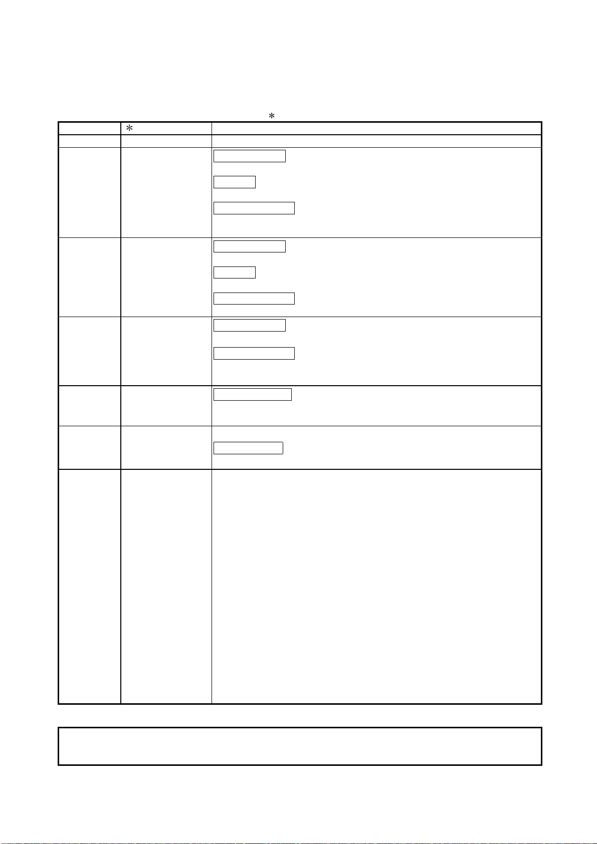
REVISIONS
The manual number is given on the bottom left of the back cover.
Print Date Manual Number Revision
Dec., 1999 SH(NA)-080037-A First edition
Sep., 2000 SH(NA)-080037-B
Addition model
Q33B, Q63B, Q63P
Addition
Section 2.3, 4.5, 11.2.3, 11.2.10, 11.2.11
Partial correction
Section 1.2, 2.2, 4.1, 4.2, 5.1.1, 5.2, 8.1.5, 11.2.1, 11.3.2, 11.5.1, 11.6,
11.7
Jun., 2001 SH(NA)-080037-C
Addition model
Q62P, Q52B, Q55B, QC05B
Addition
Section 6.6
Partial correction
Section 2.1, 2.2, 4.1, 4.2, 5.1.5, 6.1, 6.2, 6.3, 8.1.5, 11.2.4, 11.7
Sep., 2001 SH(NA)-080037-D
Addition model
Q64P
Partial correction
CONTENTS, Section 4.1, 5.1.1, 5.1.2, 5.2, 6.1, 6.2, 8.1.5, 11.5.1,
Appendix1.2, 2.2
Apr., 2002 SH(NA)-080037-E
Partial correction
Chapter 1, Section 1.1, 2.1, 2.2, 2.3, 4.1, 5.1.1, 7.1, 7.2, 7.3, 10.3.1,
10.3.2
Oct., 2002 SH(NA)-080037-F
Complete review
Addition model
Q32SB, Q33SB, Q35SB, Q61SP
Japanese Manual Version SH-080019-I
This manual confers no industrial property rights or any rights of any other kind, nor does it confer any patent
licenses. Mitsubishi Electric Corporation cannot be held responsible for any problems involving industrial property
rights which may occur as a result of using the contents noted in this manual.
1999 MITSUBISHI ELECTRIC CORPORATION
A - 6 A - 6

INTRODUCTION
Thank you for choosing the Mitsubishi MELSEC-Q Series of General Purpose Programmable Controllers.
Please read this manual carefully so that equipment is used to its optimum.
CONTENTS
SAFETY PRECAUTIONS............................................................................................................................A- 1
REVISIONS ..................................................................................................................................................A- 6
CONTENTS ..................................................................................................................................................A- 7
About Manual................................................................................................................................................A-17
How to Use This Manuals ............................................................................................................................A-18
About the Generic Terms and Abbreviations...............................................................................................A-19
1 OVERVIEW 1- 1 to 1- 4
1.1 Features..................................................................................................................................................1- 2
2 SYSTEM CONFIGURATION FOR SINGLE CPU SYSTEM 2- 1 to 2- 8
2.1 System Configuration............................................................................................................................. 2- 1
2.2 Precaution on System Configuration.....................................................................................................2- 6
2.3 Confirming the Serial Number and Function Version............................................................................2- 8
3 GENERAL SPECIFICATIONS 3- 1 to 3- 2
4 HARDWARE SPE CI F I CATI ON O F TH E CPU MODULE 4- 1 to 4 - 9
4.1 Performance Specification .....................................................................................................................4- 1
4.2 Part Names and Settings .......................................................................................................................4- 4
4.3 Switch Operation After Writing in Program............................................................................................4- 7
4.4 Latch Clear Operation ............................................................................................................................4- 8
4.5 Executing Automatic Write to Standard ROM....................................................................................... 4- 8
5 POWER SUPPLY MODULE 5- 1 to 5- 11
5.1 Specification............................................................................................................................................5- 1
5.1.1 Power supply module specifications .............................................................................................. 5- 1
5.1.2 Selecting the power supply module................................................................................................5- 6
5.1.3 Precauti on wh en connect in g th e unin te r rupt ive powe r supply......................................................5- 8
5.2 Names of Parts and Settings .................................................................................................................5- 9
6 BASE UNIT AND EXTENSION CABLE 6- 1 to 6- 11
6.1 Base Unit Specification Table ................................................................................................................ 6- 1
6.2 Extension Cable Specification Table.....................................................................................................6- 3
6.3 Parts Names of Base Unit......................................................................................................................6- 3
6.4 Setting the Extension Base Unit ............................................................................................................6- 6
A - 7 A - 7

6.5 I/O Number Allocation ............................................................................................................................6- 7
6.6 Guideline fo r U se o f Ex ten si on Ba se Un it s (Q5B) .............................................................................6- 8
7 MEMORY CARD AND BATTERY 7- 1 to 7- 6
7.1 Memory Card Specifications.................................................................................................................. 7- 1
7.2 Battery Specifications (For CPU Module and SRAM Card)..................................................................7- 2
7.3 Handling the Memory Card....................................................................................................................7- 3
7.4 The Names of The Parts of The Memory Card.....................................................................................7- 4
7.5 Memory Card Loading/Unloading Procedures...................................................................................... 7- 5
7.6 Installation of Battery (For CPU Module and Memory Card)................................................................ 7- 6
8 EMC AND LOW VOLTAGE DIRECTIVE 8- 1 to 8-11
8.1 Requirements for Conformance to EMC Directive................................................................................8- 1
8.1.1 Standards applicable to the EMC Directive....................................................................................8- 1
8.1.2 Installation instructions for EMC Directive......................................................................................8- 2
8.1.3 Cables..............................................................................................................................................8- 3
8.1.4 Power supply module......................................................................................................................8- 5
8.1.5 When using QA1S6
8.1.6 Others..............................................................................................................................................8- 8
8.2 Requirement to Conform to the Low Voltage Directive.........................................................................8- 9
8.2.1 Standard applied for MELSEC-Q series PLC................................................................................8- 9
8.2.2 MELSEC-Q series PLC selection...................................................................................................8- 9
8.2.3 Power supply..................................................................................................................................8- 10
8.2.4 Control box.....................................................................................................................................8- 10
8.2.5 Grounding.......................................................................................................................................8- 11
8.2.6 External wiring................................................................................................................................8- 11
B type base unit ........................................................................................ 8- 5
9 LOADING AND INSTALLATION 9- 1 to 9-26
9.1 General Safety Requirements................................................................................................................ 9- 1
9.2 Calculating Heat Generation by PLC..................................................................................................... 9- 6
9.3 Module Installation..................................................................................................................................9- 9
9.3.1 Precaution on installation................................................................................................................9- 9
9.3.2 Instructions for mounting the base unit ..........................................................................................9-12
9.3.3 Installation and removal of module................................................................................................. 9-15
9.4 How to Set Stage Numbers for the Extension Base Unit......................................................................9-19
9.5 Connection and Disconnection of Extension Cable ..............................................................................9-20
9.6 Wiring......................................................................................................................................................9-23
9.6.1 The precautions on the wiring.........................................................................................................9-23
9.6.2 Connecting to the power supply module ........................................................................................ 9-26
10 MAINTENANCE AND INSPECTION 10- 1 to 10- 8
10.1 Daily Inspection ..................................................................................................................................10- 2
10.2 Periodic Inspection.............................................................................................................................10- 3
10.3 Battery Replacement..........................................................................................................................10- 4
10.3.1 Battery life....................................................................................................................................10- 5
10.3.2 Battery replacement procedure..................................................................................................10- 7
A - 8 A - 8

11 TROUBLESHOOTING 11- 1 to 11-99
11.1 Troubleshooting Basics......................................................................................................................11- 1
11.2 Troubleshooting..................................................................................................................................11- 2
11.2.1 Troubleshooting flowchart...........................................................................................................11- 2
11.2.2 Flowchart for when the "MODE" LED is not turned on..............................................................11- 3
11.2.3 Flowchart for when the "MODE" LED is flickering.....................................................................11- 4
11.2.4 Flowchart for when the "POWER" LED is turned off .................................................................11- 5
11.2.5 Flowchart for when the "RUN" LED is turned off .......................................................................11- 6
11.2.6 When the "RUN" LED is flickering..............................................................................................11- 7
11.2.7 Flowchart for when the "ERR." LED is on/flickering ..................................................................11- 7
11.2.8 When the "USER" LED is turned on...........................................................................................11- 8
11.2.9 When the "BAT." LED is turned on.............................................................................................11- 8
11.2.10 Flowchart for when the "BOOT" LED is flickering.................................................................... 11- 9
11.2.11 Flowchart for when output module LED is not turned on ........................................................11-10
11.2.12 Flowchart for when output load of output module does not turn on........................................11-11
11.2.13 Flowchart for when unable to read a program.........................................................................11-12
11.2.14 Flowchart for when unable to write a program.........................................................................11-13
11.2.15 Flowchart for when it is unable to perform boot operation from memory card .......................11-15
11.2.16 Flowchart for when UNIT VERIFY ERR. occurs......................................................................11-16
11.2.17 Flowchart for when CONTROL BUS ERR. occurs..................................................................11-17
11.3 Error Code List....................................................................................................................................11-18
11.3.1 Procedure for reading error codes..............................................................................................11-18
11.3.2 Error code list ..............................................................................................................................11-19
11.4 Canceling of Errors.............................................................................................................................11-37
11.5 I/O Module Troubleshooting...............................................................................................................11-38
11.5.1 Input circuit troubleshooting........................................................................................................11-38
11.5.2 Output circuit troubleshooting.....................................................................................................11-41
11.6 Special Relay List...............................................................................................................................11-42
11.7 Special Register List...........................................................................................................................11-64
APPENDICES App- 1 to App-17
APPENDIX 1 Error Code Return to Origin During General Data Processing........................................App- 1
APPENDIX 1.1 Error code overall explanation ...................................................................................App- 1
APPENDIX 1.2 Description of the errors of the error codes (4000
H
to 4FFFH) .................................App- 2
APPENDIX 2 External Dimensions .........................................................................................................App- 7
APPENDIX 2.1 CPU module ...............................................................................................................App- 7
APPENDIX 2.2 Power supply module.................................................................................................App- 7
APPENDIX 2.3 Main base unit ............................................................................................................App-10
APPENDIX 2.4 Slim type main base unit............................................................................................App-12
APPENDIX 2.5 Extension base unit....................................................................................................App-13
APPENDIX 3 Upgraded Functions of High Performance Model QCPU ................................................App-16
APPENDIX 3.1 Specification comparison ...........................................................................................App-16
APPENDIX 3.2 Function comparison..................................................................................................App-16
APPENDIX 3.3 Added functions and the corresponding GX Developer versions.............................App-17
INDEX Index- 1 to Index- 2
A - 9 A - 9

(Related manual) ....................................................High Performance model QCPU (Q Mode) User's Manual
(Function Explanation, Program Fundamentals)
CONTENTS
1 OVERVIEW
1.1 Features
1.2 Programs
1.3 Convenient Programming Devices and Instructions
2 SYSTEM CONFIGURATION FOR SINGLE CPU SYSTEM
2.1 System Configuration
2.2 Precaution on System configuration
2.3 Confirming the Serial Number and Function Version
3 PERFORMANCE SPECIFICATION
4 SEQUENCE PROGRAM CONFIGURATION & EXECUTION CONDITIONS
4.1 Sequence Program
4.1.1 Main routine program
4.1.2 Sub-routine programs
4.1.3 Interrupt programs
4.2 Program Execute Type
4.2.1 Initial execution type program
4.2.2 Scan execution type program
4.2.3 Low speed execution type program
4.2.4 Stand-by type program
4.2.5 Fixed scan execution type program
4.3 Operation processing
4.3.1 Initial processing
4.3.2 I/O refresh (I/O module refresh processing)
4.3.3 Automatic refresh of the intelligent function module
4.3.4 END processing
4.4 RUN, STOP, PAUSE Operation Processing
4.5 Operation Processing during Momentary Power Failure
4.6 Data Clear Processing
4.7 I/O Processing and Response Lag
4.7.1 Refresh mode
4.7.2 Direct mode
4.8 Numeric Values which Can Be Used in Sequence Programs
4.8.1 BIN (Binary code)
4.8.2 HEX (Hexadecimal)
4.8.3 BCD (Binary Coded Decimal)
A - 10 A - 10

4.8.4 Real numbers (floating decimal point data)
4.9 Character String Data
5 ASSIGNMENT OF I/O NUMBERS
5.1 Relationship Between the Number of Stages and Slots of the Extension Base Unit
5.2 Installing Extension Base Units and Setting the Number of Stages
5.3 Base Unit Assignment (Base Mode)
5.4 What are I/O Numbers?
5.5 Concept of I/O Number Assignment
5.5.1 I/O numbers of main base unit and extension base units
5.5.2 Remote station I/O number
5.6 I/O Assignment by GX Developer
5.6.1 Purpose of I/O assignment by GX Developer
5.6.2 Concept of I/O assignment using GX Developer
5.7 Examples of I/O Number Assignment
5.8 Checking the I/O Numbers
6 HIGH PERFORMANCE MODEL QCPU FILES
6.1 About the High Performance model QCPU's Memory
6.2 Program Memory
6.3 About the Standard ROM
6.4 About the Standard RAM
6.5 Memory Card
6.6 Writing Data to the Standard ROM or the Flash Card
6.6.1 Writing Data to the standard ROM or to the Flash card using GX Developer
6.6.2 Automatic write to standard ROM
(Auto Down load all data from Memory card to standard ROM)
6.7 Executing Standard ROM/Memory Card Programs (Boot Run)
6.8 Program File Configuration
6.9 GX Developer File Operation and File Handling Precautions
6.9.1 File operation
6.9.2 File handling precautions
6.9.3 File size
7 FUNCTION
7.1 Function List
7.2 Constant Scan
7.3 Latch Functions
7.4 Setting the Output (Y) Status when Changing from/to STOP Status to/from RUN Status
7.5 Clock Function
A - 11 A - 11

7.6 Remote Operation
7.6.1 Remote RUN/STOP
7.6.2 Remote PAUSE
7.6.3 Remote RESET
7.6.4 Remote latch clear
7.6.5 Relationship of the remote operation and High Performance model QCPU RUN/STOP switch
7.7 Changing the Input Response Speed of the Q Series Compatible Module (I/O Response Time)
7.7.1 Selecting the response time of the input module
7.7.2 Selecting the response time of the high speed input module
7.7.3 Selecting the response time of the interrupt module
7.8 Setting the Switches of the Intelligent Function Module
7.9 Monitoring Function
7.9.1 Monitor condition setting
7.9.2 Monitoring test for local device
7.9.3 Forced ON/OFF of external I/O
7.10 Writing in Program during High Performance model QCPU RUN
7.10.1 Writing data in the circuit mode during the RUN status
7.10.2 Writing a batch of files during RUN
7.11 Execution Time Measurement
7.11.1 Program monitor list
7.11.2 Interrupt program monitor list
7.11.3 Scan time measurement
7.12 Sampling Trace Function
7.13 Debug Function with Multiple Users
7.13.1 Multiple-user monitoring function
7.13.2 Multiple-user RUN write function
7.14 Watch dog timer (WDT)
7.15 Self-Diagnosis Function
7.15.1 Interrupt due to error occurrence
7.15.2 LED display when error occurs
7.15.3 Cancel error
7.16 Failure History
7.17 System Protect
7.17.1 Password registration
7.17.2 Remote password
7.18 Monitoring High Performance model QCPU System Status from GX Developer (System Monitor)
7.19 LED Display
7.19.1 LED display
7.19.2 Priority setting
7.20 High Speed Interrupt Function
7.21 Module Service Interval Time Reading
A - 12 A - 12

8 COMMUNICATION WITH INTELLIGENT FUNCTION MODULE/SPECIAL FUNCTION MODULE
8.1 Communication Between High Performance model QCPU and Q-series Intelligent Function Modules
8.1.1 Initial setting and automatic refresh setting using GX Configurator
8.1.2 Communication using device initial value
8.1.3 Communication using FROM/TO instruction
8.1.4 Communication using the intelligent function module device
8.1.5 Communication using the instructions dedicated for intelligent function modules
8.2 Request from Intelligent Function Module to High Performance model QCPU
8.2.1 Interrupt from the intelligent function module
8.3 Communication Between High Performance model QCPU and AnS-Series Special Function Modules
8.3.1 Communication using device initial value
8.3.2 Communication using FROM/TO instruction
8.3.3 Communication using the intelligent function module device
8.3.4 Effects of quicker access to the special function module and countermeasures against them
9 PARAMETER LIST
10 DEVICES
10.1 Device List
10.2 Internal User Devices
10.2.1 Inputs (X)
10.2.2 Outputs (Y)
10.2.3 Internal relays (M)
10.2.4 Latch relays (L)
10.2.5 Anunciators (F)
10.2.6 Edge relay (V)
10.2.7 Link relays (B)
10.2.8 Link special relays (SB)
10.2.9 Step relays (S)
10.2.10 Timers (T)
10.2.11 Counters (C)
10.2.12 Data registers (D)
10.2.13 Link registers (W)
10.2.14 Link special registers (SW)
10.3 Internal System Devices
10.3.1 Function devices (FX, FY, FD)
10.3.2 Special relays (SM)
10.3.3 Special registers (SD)
10.4 Link Direct Devices (J
\ )
A - 13 A - 13

10.5 Intelligent Function Module Devices (U
10.6 Index Registers (Z)
10.6.1 Switching between scan execution type programs and low speed execution type programs
10.6.2 Switching between scan/low speed execution programs and interrupt/fixed scan execution type
programs
10.7 File Registers (R)
10.7.1 File register capacity
10.7.2 Differences in memory card access method by memory card type
10.7.3 Registering the file registers
10.7.4 File register designation method
10.7.5 Precautions in using file registers
10.8 Nesting (N)
10.9 Pointers
10.9.1 Local pointers
10.9.2 Common pointers
10.10 Interrupt Pointers (I)
10.11 Other Devices
10.11.1 SFC block device (BL)
10.11.2 SFC transition device (TR)
10.11.3 Network No. designation device (J)
10.11.4 I/O No. designation device (U)
10.11.5 Macro instruction argument device (VD)
10.12 Constants
10.12.1 Decimal constants (K)
10.12.2 Hexadecimal constants (H)
10.12.3 Real numbers (E)
10.12.4 Character string ( " " )
10.13 Convenient Uses for Devices
10.13.1 Global devices & local devices
10.13.2 Device initial values
\G )
11 HIGH PERFORMANCE MODEL QCPU PROCESSING TIME
11.1 Reading High Performance model QCPU's Scan Time
11.2 Factors Responsible for Extended Scan Time
Factors Responsible for Shortened Scan Time
12 PROCEDURE FOR WRITING PROGRAMS TO HIGH PERFORMANCE MODEL QCPU
12.1 Writing Procedure for 1 Program
12.1.1 Items to consider when creating one program
12.1.2 Procedure for writing programs to the High Performance model QCPU
12.2 Procedure for Multiple Programs
12.2.1 Items to consider when creating multiple programs
12.2.2 Procedure for writing programs to the High Performance model QCPU
A - 14 A - 14

13 OUTLINE OF MULTIPLE CPU SYSTEMS
13.1 Features
13.2 Outline of Multiple CPU Systems
13.3 Differences with Single CPU Systems
14 SYSTEM CONFIGURATION OF MULTIPLE CPU SYSTEMS
14.1 System Configuration
14.2 Precautions During Multiple CPU System Configuration
14.2.1 Function versions of High Performance model QCPU , motion CPUs and PC CPU module that
can be sued, and their mounting positions
14.2.2 Precautions when using Q series corresponding I/O modules and intelligent function modules
14.2.3 Limitations when mounting AnS series corresponding I/O modules and special function modules
14.2.4 Modules that have mounting restrictions
14.2.5 Usable GX Developers and GX Configurators
14.2.6 Parameters that enable the use of multiple CPU systems
14.2.7 Resetting the multiple CPU system
14.2.8 Processing when High Performance model QCPU stop errors occur
14.2.9 Reducing the time required for multiple CPU system processing
15 ALLOCATING MULTIPLE CPU SYSTEM I/O NUMBERS
15.1 Concept behind Allocating I/O Numbers
15.1.1 I/O modules and intelligent function module I/O numbers
15.1.2 I/O number of High Performance model QCPU, Motion CPU and PC CPU module
15.2. Purpose of PC Parameter I/O Allocations with the GX Developer
16 COMMUNICATION BETWEEN THE MULTIPLE CPU SYSTEM'S QCPUS AND MOTION CPUs
16.1 Automatic Refresh of Common CPU Memory
16.2 Communication with Multiple CPU Commands and Intelligent Function Module Devices
16.3 Interactive Communications between The High Performance model QCPU and Motion CPU
16.3.1 Control instructions from the High Performance model QCPU to the Motion CPU
16.3.2 Reading and writing device data
16.4 Common CPU Memory
17 COMMUNICATIONS BETWEEN THE MULTIPLE CPU SYSTEM'S I/O MODULES AND
INTELLIGENT FUNCTION MODULES
17.1 Range of Control PLC Communications
17.2 Range of Non-control PLC Communications
A - 15 A - 15

18 PROCESSING TIME FOR MULTIPLE CPU SYSTEM HIGH PERFORMANCE MODEL
QCPUs
18.1 Concept behind QCPU Scanning Time
18.2 Factor to Prolong the Scan Time
19 STARTING UP THE MULTIPLE CPU SYSTEM
19.1 Flow-chart for Starting Up the Multiple CPU System
19.2 Setting Up the Multiple CPU System Parameters (Multiple PLC Settings, Control PLC Settings)
19.2.1 System configuration
19.2.2 Creating new systems
19.2.3 Using existing preset multiple CPU settings and I/O allocations
APPENDICES
APPENDIX 1 Special Relay List
APPENDIX 2 Special Register List
APPENDIX 3 List of Interrupt Pointer Nos. and Interrupt Factors
INDEX
A - 16 A - 16

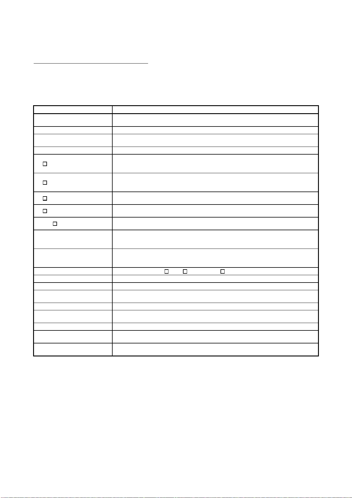
About Manuals
The following manuals are related to this product.
Referring to this list, please request the necessary manuals.
Related Manuals
Manual Name
High Performance model QCPU (Q Mode) User's M anual (Function Explanation, Program
Fundamentals)
This manual explains the functions, programming methods, devices and so on necessary to create
programs with the High Performance model QCPU. (sold separately)
Manual Number
(Model Code)
SH-080038
(13JL98)
QCPU (Q Mode)/QnACPU Programming Manual (Common Instructions)
This manual describes how to use the sequence instructions, basic instructions and application
instructions. (sold separately)
QCPU (Q Mode)/QnACPU Programming Manual (PID Control Instructions)
This manual describes the dedicated instructions used to exercise PID control. (sold separately)
QCPU (Q Mode)/QnACPU Programming Manual (SFC)
This manual explains the system configuration, performance specifications, functions, programming,
debugging, error codes and others of MELSAP3. (sold separately)
QCPU (Q Mode) Programming Manual (MELSAP-L)
This manual describes the programming methods, specifications, functions, and so on that are
necessary to create the MELSAP-L type SFC programs. (sold separately)
SH-080039
(13JF58)
SH-080040
(13JF59)
SH-080041
(13JF60)
SH-080076
(13JF61)
A - 17 A - 17

How to Use This Manual
This manual is prepared for users to understand the hardware specifications of those modules such as the
CPU modules, power supply modules, and base units, maintenance and inspections of the system, and
troubleshooting required when you use MELSEC-Q series PLCs.
The manual is classified roughly into three sections as shown below.
1) Chapters 1 and 2 Describe the outline of the CPU module and the system
configuration.
The basics of the system configuration of CPU module are
described.
2) Chapters 3 to 7 Describe the general specifications indicating the operating
environments of the CPU module, power supply module, and
base units, and the performance specifications of these
modules.
3) Chapters 8 to 10 Describe the overall maintenance such as the installation of the
CPU module, daily inspections, and troubleshooting.
REMARK
This manual does not explain the functions of the CPU module.
For these functions, refer to the manual shown below.
• High Performance model QCPU (Q Mode) User's Manual (Function Explanation,
Program Fundamentals)
A - 18 A - 18
About the Generic Terms and Abbreviations
This manual uses the following general names and abbreviations in the descriptions of the High
Performance model QCPU unless otherwise specified.
Generic Term/Abbreviation Description
High Performance model
QCPU
Q Series Abbreviation for Mitsubishi MELSEC-Q Series Programmable Logic Controller.
AnS Series
GX Developer General name for GX Developer Version 4 or later.
Q3 B
Q3 SB
Q5 B
Q6 B
QA1S6 B
Main base unit
Slim type main base unit
Extension base unit General name for Q5 B, Q6 B and QA1S6 B.
SRAM card Abbreviation for Q2MEM-1MBS, Q2MEM-2MBS type SRAM card.
Flash card General name for Q2MEM-2MBF and Q2MEM-4MBF types Flash card.
ATA card
Memory card General name for SRAM card, Flash card and ATA card.
Power supply module
Slim type power supply module General name for Q61SP slim type power supply module
Battery
Extension cable
General name for Q02CPU, Q02HCPU, Q06HCPU, Q12HCPU, and Q25HCPU
modules.
Abbreviation for small types of Mitsubishi MELSEC-A Series Programmable Logic
Controller.
General name for Q33B, Q35B, Q38B, Q312B type main base unit with High
Performance model QCPU and Q Series power supply module, I/O module and
intelligent function module attachable.
General name for Q32SB, Q33SB, Q35SB slim type main base unit with High
Performance model QCPU and slim type power supply module, I/O module and
intelligent function module attachable.
General name for Q52B and Q55B type extension base unit with Q Series I/O module
and intelligent function module attachable.
General name for Q63B, Q65B, Q68B and Q612B type extension base unit with Q
Series power supply module, I/O module and intelligent function module attachable.
General name for QA1S65B and QA1S68B type extension base unit with AnS Series
power supply module, I/O module and special function module attachable.
General name for Q33B, Q35B, Q38B, Q312B type main base unit with High
Performance model QCPU and Q Series power supply module, I/O module and
intelligent function module attachable.
General name for Q32SB, Q33SB, Q35SB slim type main base unit with High
Performance model QCPU and slim type power supply module, I/O module and
intelligent function module attachable.
General name for Q2MEM-8MBA, Q2MEM-16MBA and Q2MEM-32MBA types ATA
card.
General name for Q61P-A1, Q61P-A2, Q62P, Q63P, Q64P, A1S61PN, A1S62P and
A1S63P types power supply module.
General name for battery for Q6BAT type CPU module and Q2MEM-BAT type SRAM
card.
General name for QC05B, QC06B, QC12B, QC30B, QC50B, QC100B type extension
cable.
A - 19 A - 19
1 OVERVIEW
1 OVERVIEW
MELSEC-Q
1
This Manual describes the hardware specifications and handling methods of the High
Performance model QCPU.
The Manual also describes those items related to the specifications of the power
supply module, main base unit, extension base unit, extension cable, memory card
and battery.
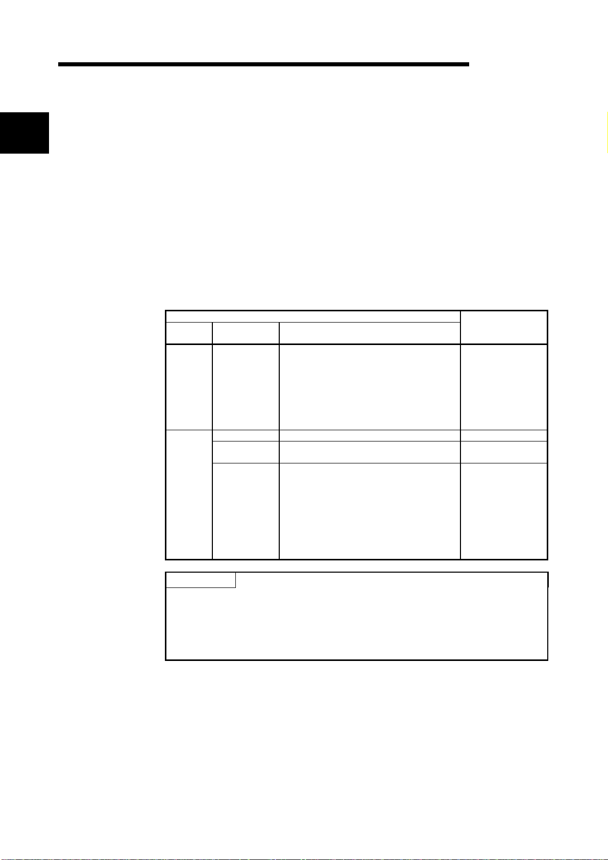
Functions are added when the High Performance model QCPU is updated.
The added functions can be discriminated by the function version/serial number of the
CPU module.
Table 1.1 gives the added functions and the corresponding GX Developer versions.
When using the added function, confirm the function version/serial number and the GX
Developer version.
Table 1.1 List of Functions Added to High Performance Model QCPU and Function
Versions/Serial Numbers
Function
version
A
B
Update Details of High Performance Model QCPU
Serial No. Added functions
• Automatic write to standard ROM
• Enforced ON/OFF for external I/O
• Remote password setting
02092" or later
"
— • Compatibility with the multiple CPU system Version 6 or later
03051" or later
"
04012" or later
"
• Increased standard RAM capacity of
Q12HCPU, Q25HCPU
• Compatibility with MELSECN ET /H remote
I/O network
• Interrupt module (QI60) compatibility
• Installation of PC CPU module into the
multiple CPU system
• High speed interrupt function
• Compatibility with index modification for
module designation of dedicated instruction
• Selection of refresh item for COM
instruction
• Extended life battery of SRAM card
• Compatibility with 2Mbyte SR AM card
• Increased standard RAM capacity of
Q02HCPU, Q06HCPU
Corresponding
GX Developer
Version 6 or later
Version 7 or later
Version 7.10L
or later
POINT
(1) For the details of the added functions in Table 1.1, refer to the High
Performance model QCPU (Q mode) User's Manual (Function Explanation,
Program Fundamentals).
(2) Refer to Section 2.3 for the serial No. and function version of the High
Performance model QCPU.
1 - 1 1 - 1

1 OVERVIEW
MELSEC-Q
1.1 Features
High Performance model QCPU has the following new features:
(1) Controllable multiple I/O points
All High Performance model QCPUs support 4096 points (X/Y0 to FFF) as the
number of actual I/O points capable of getting access to the I/O module installed
on the base unit.
They also support 8192 points max. (X/YO to 1FFF) as the number of I/O
devices which can be used in the remote I/O stations such as MELSECNET/H
remote I/O NET, CC-Link data link and MELSECNET/MINI-S3 data link.
(2) Lineup according to progr am capaci ty
The optimum CPU module for the program capacity to be used can be selected.
Q02CPU, Q02HCPU : 28k step
Q06HCPU : 60k step
Q12HCPU : 124k step
Q25HCPU : 252k step
(3) Realised high speed processing
Depending on the type of the sequencer, high speed processing has been
realized.(Example: when LD instruction is used)
Q02CPU : 0.079
Q02HCPU, Q06HCPU, Q12HCPU, Q25HCPU : 0.034
In addition, an access to the intelligent function module or an increase in speed
of the link refresh of the network have been realized by the connection system
(System bus connection) of the newly developed base unit.
Access to the intelligent function module : 20
MELSECNET/H link refresh processing : 4.6ms/8k word (approx. 4.3 times)
1: Where Q02HCPU is compared with Q2ASHCPU-S1.
s /word (approx. 7 times) 1
s
s
(4) Increase in debugging efficiency thr oug h high speed
communication with GX Dev el oper
In the High Performance model QCPU, a time required for writing/reading of a
program or monitoring has been reduced through the high speed communication
at a speed of 115.2kbps max. by the RS-232, and a communication time
efficiency at the time of debugging has been increased.
In the Q02HCPU, Q06HCPU, Q12HCPU, and Q25HCPU, a high speed
communication at a speed of 12Mbps is allowed through the USB.
26k step program transfer time
1
1
Q25HCPU(USB)
Q25HCPU(RS-232)
Q2ASHCPU
A2USHCPU-S1
12
30
0 1020304050607080
86
94
90 100
(Unit:s)
(5) AnS series I/O module or special function module are available.
For Q series, if an appropriate module is not available, the AnS series I/O
module or special function module can also be used for the High Performance
model QCPU through the use of the QA1S65B/QA1S68B extension base unit.
1 - 2 1 - 2
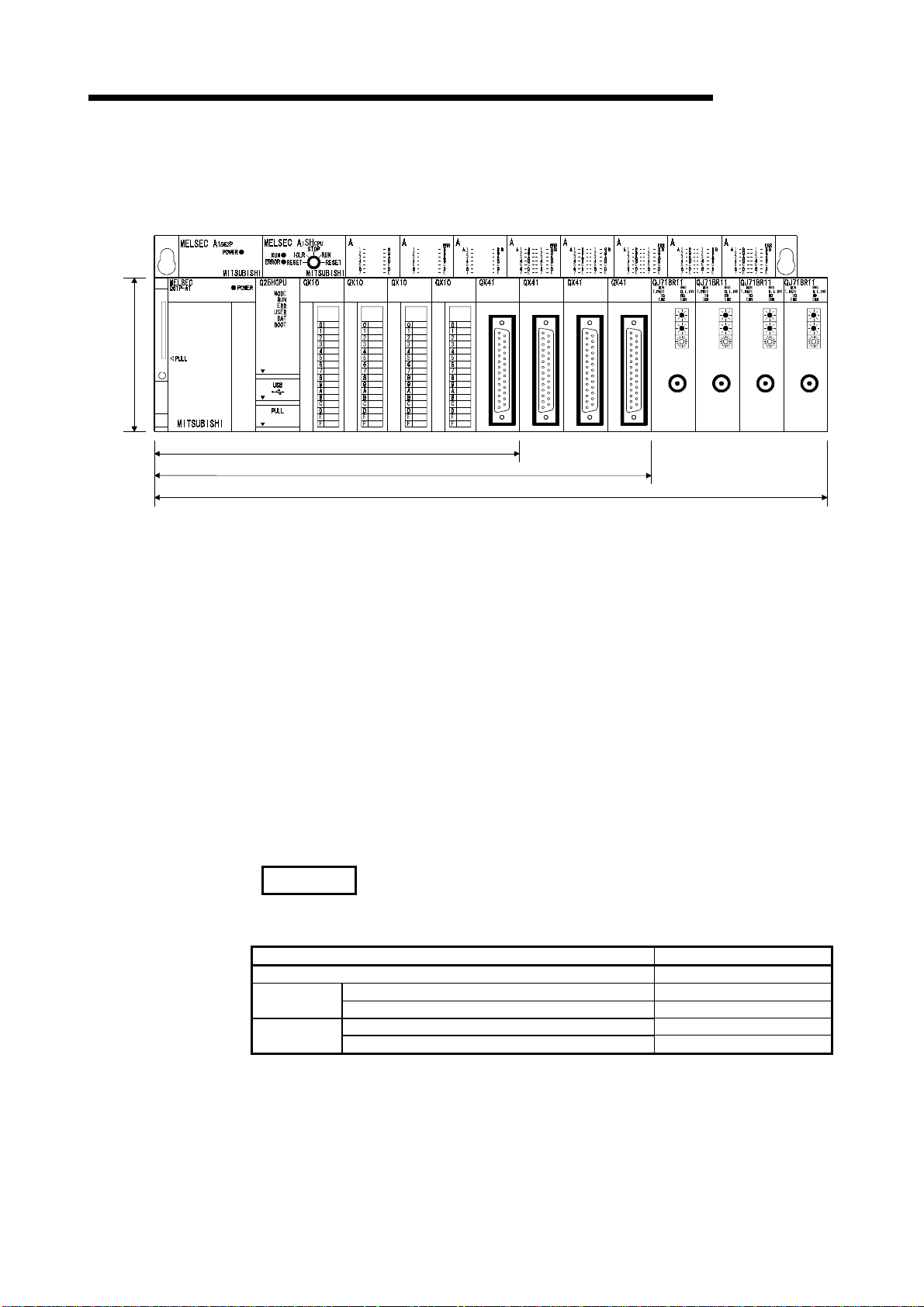
1 OVERVIEW
Comparison of installation space
98mm
(3.86
inch)
(6) Saved space by a reduction in si z e
The installation space for Q series has been reduced by approx. 60 % of the
space for AnS series.
1SX10 1SY50 1SX41 1SY41 1SX81 1SY81 1SX42 1SY42
PULL
MELSEC-Q
5 Slot Main Base Unit 245mm(9.65inch)
8 Slot Main Base Unit 328mm(12.92inch)
12 Slot Main Base Unit 439mm(17.30inch)
(depth:98mm(3.86inch))
(7) Connection of up to seven extension base units.
(a) The High Performance model QCPU can connect to seven extension base
units (eight base units including the main) and accept up to 64 modules.
(b) The overall distance of the extension cables is up to 13.2m to ensure high
degree of extension base unit arrangement.
(8) Memory extension by memory card
The High Performance model QCPU is provided with a memory card installation
connector to which a memory card of 32 Mbyte max. can be connected (32
Mbyte is available when a ATA card is used).
When a memory card of large capacity is installed, a large capacity of file can be
controlled, comments to all data devices can be set up, and the programs in the
past can be stored in the memory as they are in the form of the corrected
histories.
If a memory card is not installed, a program can be stored onto the standard
ROM built in the CPU module, and file registers can be handled by the standard
RAM.
REMARK
• The number of file registers that can be handled changes depending on the
function version/serial number of the CPU module used.
CPU Module Type Number of File Registers
Q02CPU 32k points
First 5 digits of serial number are "04011" or earlier 32k points Q02HCPU
Q06HCPU
Q25HCPU
First 5 digits of serial number are "04012" or later 64k points
First 5 digits of serial number are "02091" or earlier 32k points Q12HCPU
First 5 digits of serial number are "02092" or later 128k points
Refer to Section 2.3 to confirm the function version and serial number of the High
Performance model QCPU.
1 - 3 1 - 3

1 OVERVIEW
MELSEC-Q
(9) Data can be written automatical ly to standard ROM
You need not use GX Developer to write parameters/programs on a memory
card to the standard ROM of the High Performance model QCPU.
When the standard ROM is used to perform ROM operation, you can load a
memory card into the High Performance model QCPU and write
parameters/programs on the memory card to the standard ROM. Hence, you
need not carry GX Developer (personal computer) to rewrite the
parameters/programs.
(10) External I/O can be turned ON/OFF forcibly
If the High Performance model QCPU is in the RUN mode, you can operate GX
Developer to turn external inputs/outputs ON/OFF forcibly, independently of the
program execution status.
You need not put the High Performance model QCPU in the STOP mode to
perform wiring/operation tests by forced ON/OFF of outputs.
(11) Remote password can be set
When access to an Ethernet module or serial communication module is made
externally, whether access to the High Performance model QCPU can be made
or not can be selected with a remote password.
(12) Remote I/O network of MELSECNET/H can be configured
You can load the remote master station of the MELSECNET/H to configure an
MELSECNET/H remote I/O system.
REMARK
• Features (9) to (12) are functions added to the High Performance model QCPU
whose serial number is "02092" or later in its upper 5 digits.
• The remote password facility can be executed when the Ethernet module or serial
communication module of function version B and GX Developer Version 6 or later
are used.
• In addition to the remote password, there are the following protection facilities for
the High Performance model QCPU.
(a) Protection of the whole CPU module by making system protection settings of
the High Performance model QCPU
(b) Protection of the memory card by setting the write protect switch of the memory
card
(c) File-by-file protection using password
• The MELSECNET/H remote I/O network facility can be executed when the
MELSECNET/H network module of function version B and GX Developer (Version
6 or later) are used.
1 - 4 1 - 4
2 SYSTEM CONFIGURATION FOR SINGLE CPU SYSTEM
2 SYSTEM CONFIGURATION FOR SINGLE CPU SYSTEM
MELSEC-Q
2.1 System Configuration
2
Memory card
(Q2MEM-1MBS,Q2MEM-2MBS,
Q2MEM-2MBF,Q2MEM-4MBF,
Q2MEM-8MBA,Q2MEM-16MBA,
Q2MEM-32MBA)
This section describes the system configuration of the High Performance model
QCPU, cautions on use of the system, and configured equipment.
The outline of the equipment configuration, configuration with peripheral devices, and
system configuration in the High Performance model QCPU system is described below.
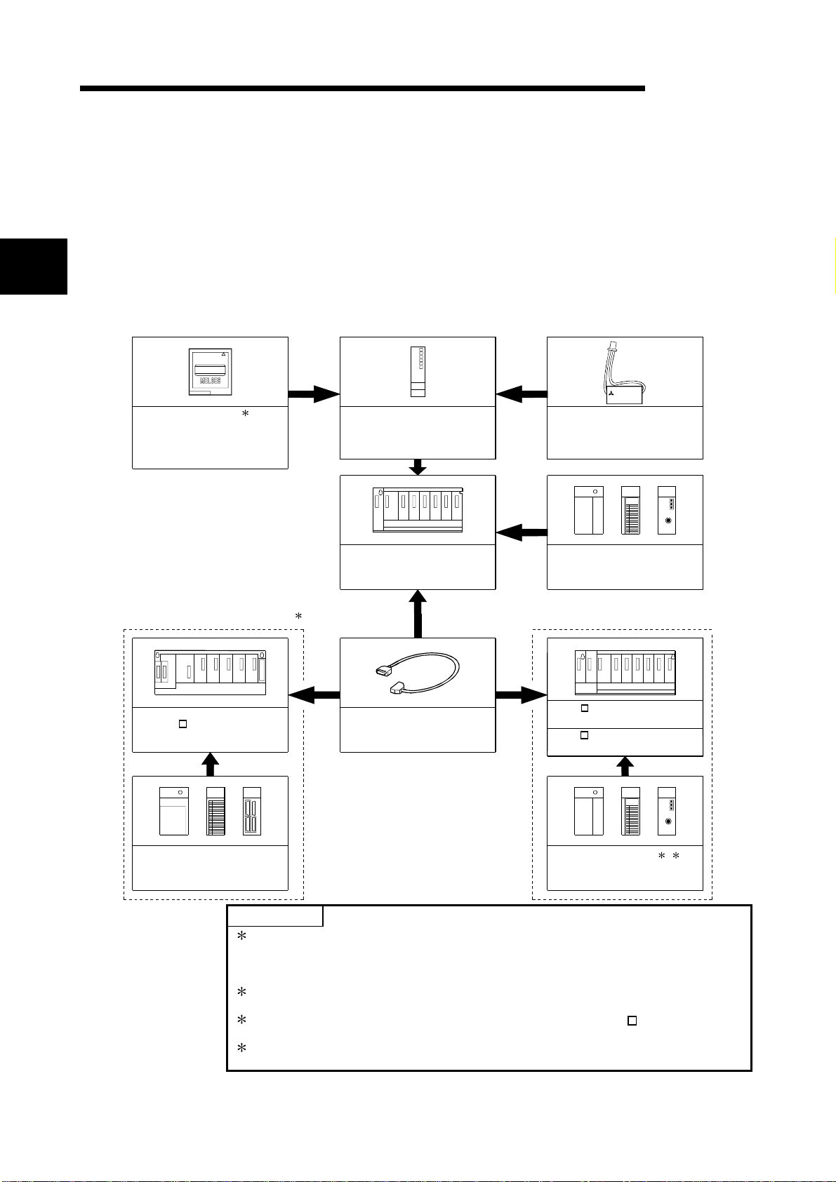
(1) Equipment configuration
(a) If the main base unit (Q3B) is used
MITSUBISHI
MITSUBISHI
LITHIUM BAT TERY
1
High Performance model QCPU
(Q02CPU,Q02HCPU,Q06HCPU,
Q12HCPU,Q25HCPU)
Main base unit
(Q33B, Q35B,Q38B,Q312B)
Battery
(Q6BAT)
Power supply module ,
I/O module , Inte l l igent function
module of the Q Series
Extension of the AnS Series module Extension of the Q Series module
2
QA1S6 extension base unit
(QA1S65B,QA1S68B)
Extension cable
(QC05B,QC06B,QC12B,
QC30B, QC50B,QC100B)
Q5 B extension base unit
(Q52B, Q55B)
Q6 B extension base unit
(Q63B, Q65B,Q68B,Q612B)
Power supply module ,
I/O module , Intelligent function
module of the AnS Series
POINTS
1: The number of memory cards to be installed is one sheet.
The memory card must be selected from SRAM card, Flash card, and ATA
Power supply module ,
I/O module , Inte l l igent function
module of the Q Series
3
4
card according to the application and capacity.
With commercial memory cards, the Operation is not assured.
2: QA1S65B and QA1S68B extension base units are used for the power supply
module, I/O module, and special function module of the AnS series.
3: The Q series power supply module is not required for the Q5 B type
extension base unit.
4: Q61SP cannot be used for the power supply module.
Use Q61P-A1, Q61P-A2, Q62P, or Q64P for the power supply module.
2 - 1 2 - 1
2 SYSTEM CONFIGURATION FOR SINGLE CPU SYSTEM
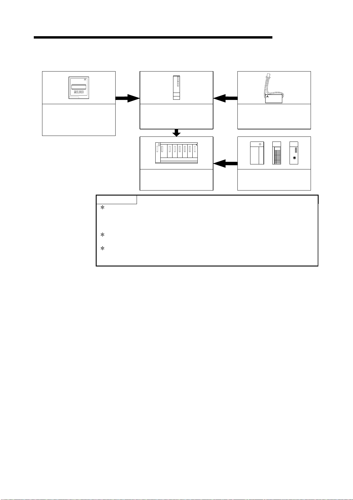
(b) If the slim type main base unit (Q3SB) is used
MITSUBISHI
(Q2MEM-1MBS,Q2MEM-2MBS,
Memory card
Q2MEM-2MBF,Q2MEM-4MBF,
Q2MEM-8MBA,Q2MEM-16MBA,
Q2MEM-32MBA)
*1
High Performance model QCPU
(Q02CPU,Q02HCPU,Q06HCPU,
Q12HCPU,Q25HCPU)
MELSEC-Q
MITSUBISHI
LITHIUM BATTERY
Battery
(Q6BAT)
Slim type main base unit
(Q32SB,Q33SB,Q35SB)
*2
Slim type power supply module,
I/O module ,
Intelligent function module
POINTS
*3
1: The number of memory cards to be installed is one sheet.
The memory card must be selected from SRAM card, Flash card, and ATA
card according to the application and capacity.
With commercial memory cards, the Operation is not assured.
2: The slim type main base unit does not have an extension cable connector. The
extension base unit and GOT cannot be connected.
3: Q61P-A1, Q61P-A2, Q62P, or Q64P cannot be used for the power supply
module.
Use Q61SP for the power supply module.
2 - 2 2 - 2
2 SYSTEM CONFIGURATION FOR SINGLE CPU SYSTEM
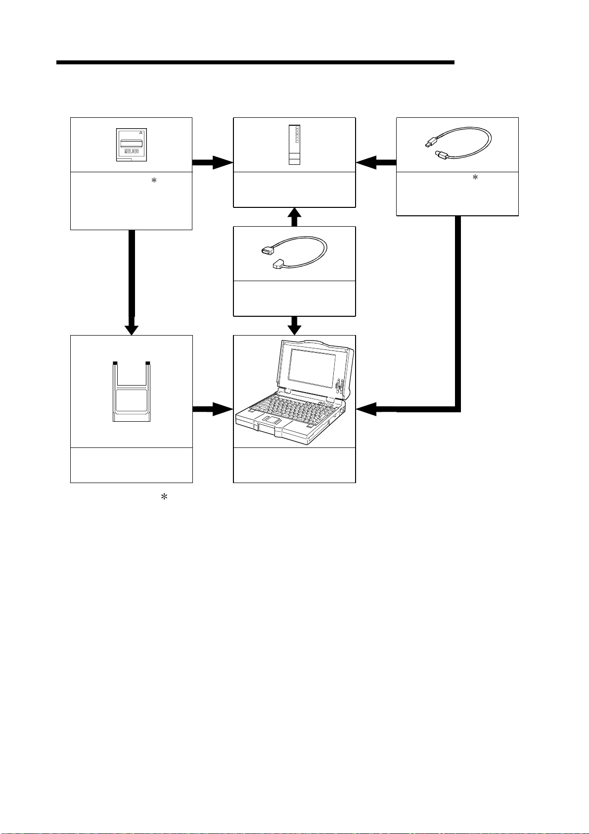
(2) Configuration of peripheral devices
MITSUBISHI
MELSEC-Q
Memory card 1
(Q2MEM-1MBS,Q2MEM-2MBS,
Q2MEM-2MBF,Q2MEM-4MBF,
Q2MEM-8MBA,Q2MEM-16MBA,
Q2MEM-32MBA)
PC card adapter
(Q2MEM-ADP)
High Performance model QCPU
(Q02CPU,Q02HCPU,Q06HCPU,
Q12HCPU,Q25HCPU)
RS-232 cable
(QC30R2)
Personal Computer
GX Developer Version 4 or later
(SW4D5C-GPPW-E or later)
USB cable 1
(To be procured yourself)
Only Q02HCPU, Q06HCPU
Q12HCPU and Q25HCPU
can be used.
1: For how to write data to the memory card and the details of the USB cable, refer to
the GX Developer Operating Manual.
2 - 3 2 - 3
2 SYSTEM CONFIGURATION FOR SINGLE CPU SYSTEM
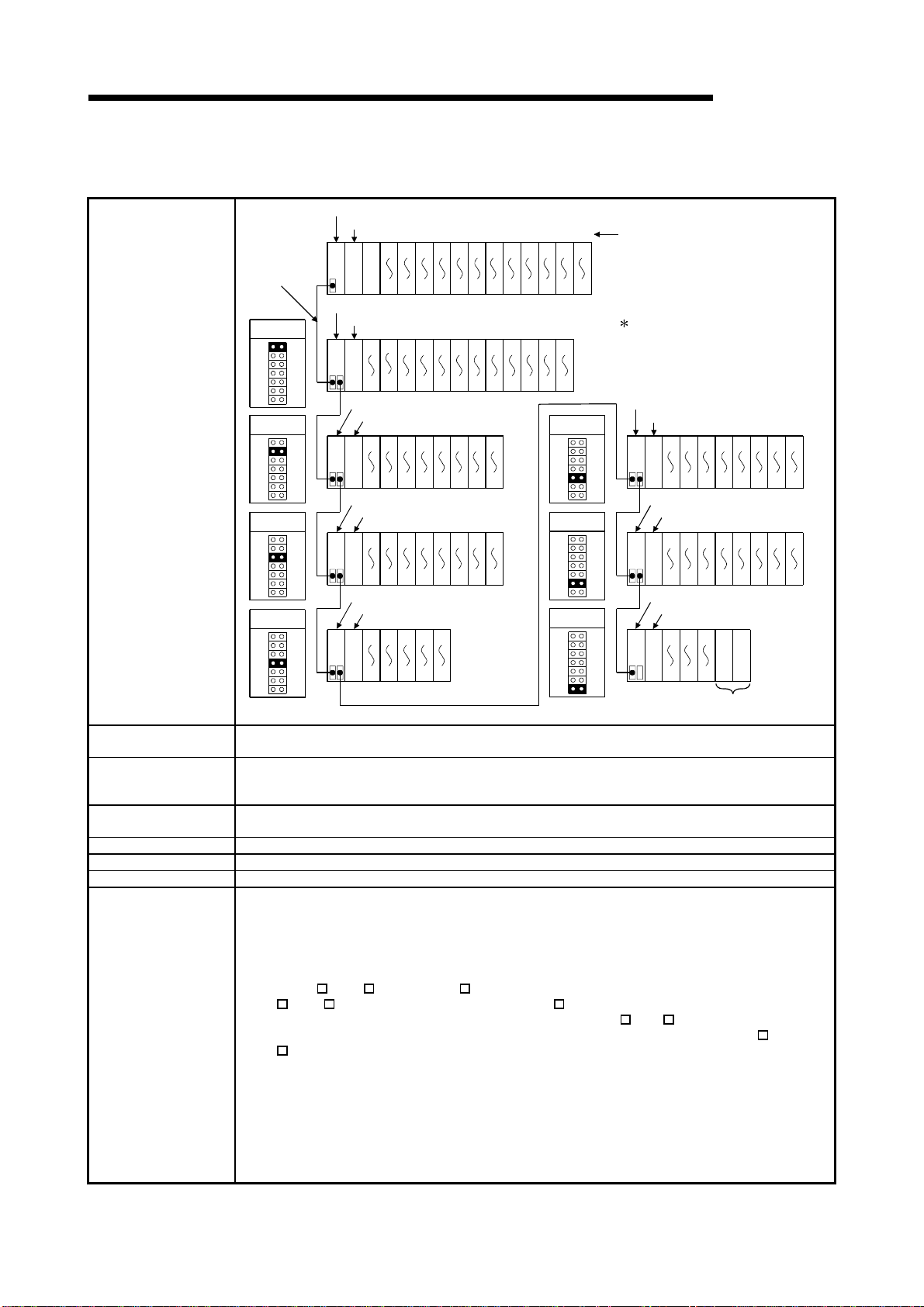
(3) Outline of system configuration
(a) If the main base unit (Q3B) is used
Main base unit(Q312B)
Power supply module
01234567891011
Extension
cable
O
U
T
001F203F405F607F809FA0BFC0DFE0FF100
CPU module
11F
120
13F
140
15F
Extension base unit(Q612B)
1st extension
stage
Power supply module
1E0
1C0
180
1A0
O
I
U
N
T
19F
1BF
1DF
1FF
200
21F
220
23F
240
25F
260
27F
280
29F
2A0
2BF
2221201918171615141312
2C0
2DF
23
2E0
2FF
Extension base unit(Q68B)
Power supply module
320
300
O
I
U
N
T
33F
31F
340
35F
360
37F
380
39F
3A0
3BF
3C0
3DF
3130292827262524
3E0
3FF
5th extension
stage
System configuration
2nd extension
stage
Extension base unit(Q68B)
3rd extension
stage
Power supply module
420
400
O
I
U
N
T
43F
41F
440
45F
460
47F
480
49F
4A0
4BF
4C0
4DF
3938373635343332
4E0
4FF
6th extension
stage
Extension base unit(Q65B)
Maximum number of
Extension Stages
4th extension
stage
Power supply module
520
500
O
I
U
N
T
53F
51F
540
55F
4443424140
580
560
59F
57F
Seven Extension Stages
7th extension
stage
Maximum number of
I/O modules to be
64 modules
installed
Maximum number of
occupied I/O points
4096
Main base unit Q33B, Q35B, Q38B, Q312B
Extension base unit Q52B, Q55B, Q63B, Q65B, Q68B, Q612B, QA1S65B, QA1S68B
Extension cable QC05B, QC06B, QC12B, QC30B, QC50B, QC100B
(1) Extension bases unit of up to seven stages can be used.
(2) Do not use extension cable longer than an overall extension length of 13.2m(43.31ft.).
(3) When using an extension cable, do not bind it together with the main circuit (high voltage and
heavy current) line or do not lay down them closely to each other.
(4) When setting the No. of the expansion stages, set it in the ascending order so that the same
No. is not set simultaneously by two extension base units.
(5) When Q5
B, Q6 B and QA1S6 B types of extension base units are mix ed, first connect the
Q5 B, Q6 B type and then connect the QA1S6 B type.
When setting the No. of the extension stages, set it from Q5
Notes
Although there are no particular restrictions in the order of the installation of the Q5
Q6 B, refer to Section 6.6 for usability.
(6) Connect the extension cable from OUT of the ex tension cable connector of the base unit to IN
of the extension base unit on the next stage.
(7) If 65 or more modules are installed, an error will occur.
(8) When the GOT is bus-connected, it occupies one extension stage and one slot.
(9) The High Performance model QCPU processes the GOT as a 16-point intelligent function
module. Hence, connecting one GOT decreases 16 points available for the base unit.
(10) Q61SP cannot be used for the power supply module.
Use Q61P-A1, Q61P-A2, Q62P, or Q64P for the power supply module.
160
17F
Slot No.
The figure shows the configuration
when 32-I/O modules are
loaded to each slot.
Extension base unit(QA1S68B)
Power supply module
600
5E0
5C0
5A0
O
I
U
N
T
5BF
5DF
5FF
61F
Extension base unit(QA1S68B)
Power supply module
700
6E0
6C0
6A0
O
I
U
N
T
6BF
6DF
6FF
71F
Extension base unit(QA1S65B)
Power supply module
636261
7E0
7C0
7A0
O
I
U
N
T
7FF
7DF
7BF
When module is installed,
an error occurs.
B/Q6 B in order.
MELSEC-Q
5251504948474645
680
660
640
620
69F
67F
65F
63F
6059585756555453
780
760
740
720
79F
77F
75F
73F
Prohibit
Prohibit
B and
2 - 4 2 - 4
2 SYSTEM CONFIGURATION FOR SINGLE CPU SYSTEM
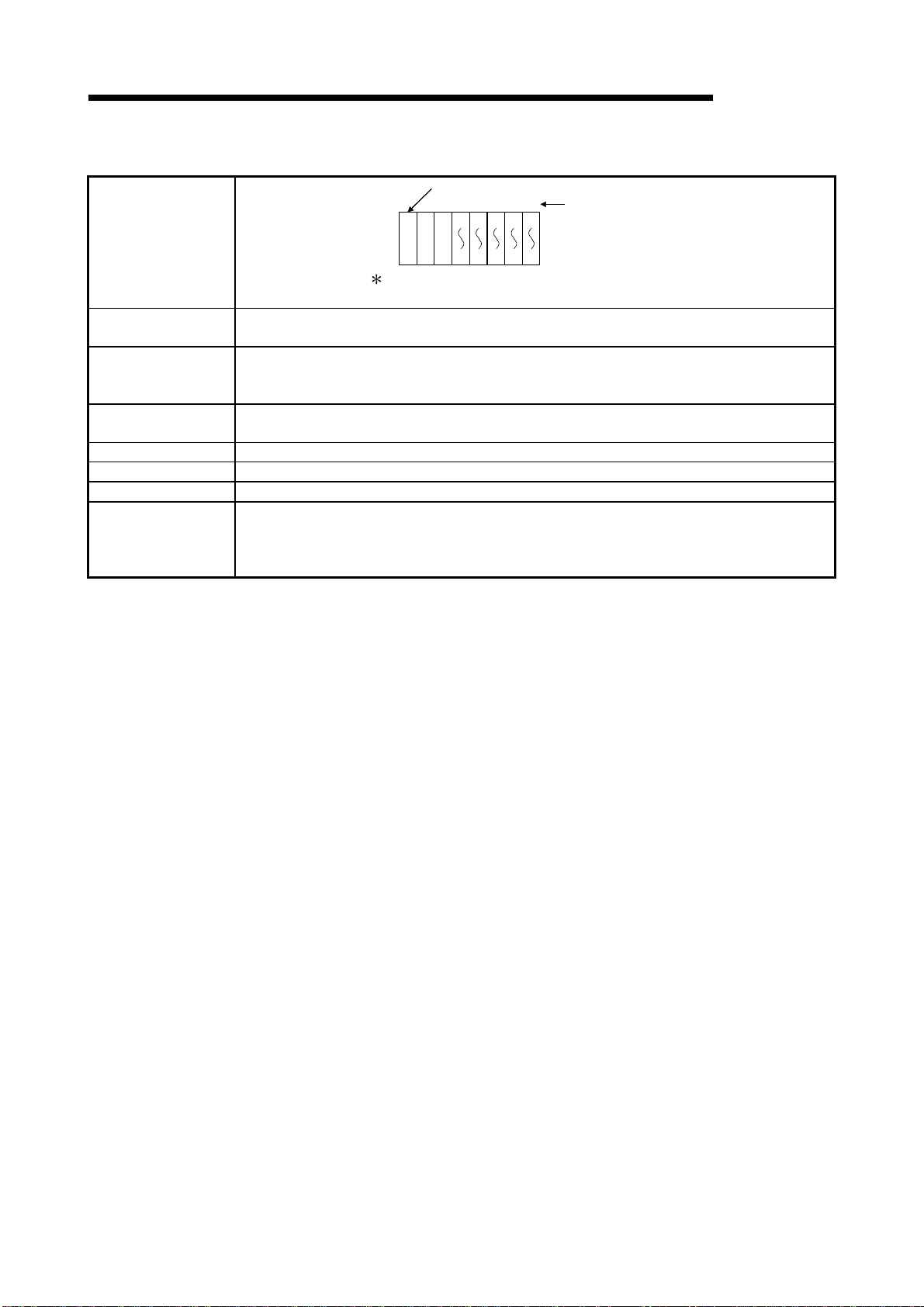
(b) If the slim type main base unit (Q3SB) is used
Slim type main base unit (Q35SB)
01234
001F203F405F607F80
Slot No.
MELSEC-Q
System configuration
The above system assumes that each slot is loading with
a 32-point module.
Maximum number of
Extension Stages
CPU module
Power supply
module
No extension allowed
9F
Maximum number of
I/O modules to be
5 modules
installed
Maximum number of
occupied I/O points
4096
Main base unit Q32SB, Q33SB, Q35SB
Extension base unit Cannot be connected.
Extension cable C annot be connected.
(1) Q61P-A1, Q61P-A2, Q62P, or Q64P cannot be used for the power supply module.
Notes
Use Q61SP for the power supply module.
(2) The slim type main base unit does not have an extension cable connector.
The extension base unit and GOT cannot be connected.
2 - 5 2 - 5
2 SYSTEM CONFIGURATION FOR SINGLE CPU SYSTEM
MELSEC-Q
2.2 Precaution on System Configuration
This section describes hardware and software packages compatible with QCPU.
(1) Hardware
(a) The number of modules to be installed and functions are limited depending on
the type of the modules.
Applicable Module Type
• QJ71LP21
Q Series MELSECNET/H
network module
Q series Ethernet interface
module
Q series CC-Link system
master local module
MELSECNET/MIN I-S3 data
link module
AnS series special function
module shown on the right
Interrupt module
• QJ71BR11
• QJ71LP21-25
• QJ71LP21G
• QJ71LP21GE
• QJ71E71
• QJ71E71-B2
• QJ71E71-100
• QJ61BT11 No limit
• A1SJ71PT32-S3
• A1SJ71T32-S3
• A1SD51S
• A1SD21-S1
• A1SJ71J92-S3
(When GET/PUT service is used)
• A1SI61
• QI60
1: A maximum of 4 modules if the network parameters for CC-Link are set and
controlled by the GX Developer. There is no restriction in the number of modules
when the parameters are set by the special-purpose instructions for the CC-Link.
For details on the CC-Link System Master Local Unit that can set parameters with
the special-purpose instructions, refer to the user's manual for the CC-Link Master
Local module.
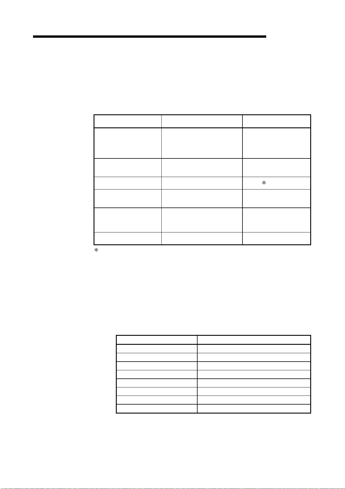
(b) When the AnS series special-function modules shown below are used, a
limitation is given to an accessible device range.
• A1SJ71J92-S3 type JEMANET interface module
• A1SD51S type intelligent communication
Device Accessible device range
Input (X), Output (Y) X/Y0 to 7FF
Internal relay (M), Latch relay (L) M0 to 8191
Link relay (B) B0 to FFF
Timer (T) T0 to 2047
Counter (C) C0 to 1023
Data register (D) D0 to 6143
Link register (W) W0 to FFF
Annunciator (F) F0 to 2047
(c) A graphic operation terminal can be used only for the GOT900 series (Basic
OS matching Q mode and communication driver must be installed).
The GOT800 series, A77GOT, and A64GOT cannot be used.
2 - 6 2 - 6
Limit of number of modules
to be installed
Up to 4 in total of inter-PLC
network and remote I/O
network modules
Up to 4 units
1
No limit
(setting of automatic refresh
function not allowed)
Total of 6 units
One unit only
Loading...