


Mitsubishi Electronics PMFY-P08NBMU-E1, PMFY-P12NBMU-E1, PMFY-P08NBMU-E, PMFY-P06NBMU-E1, PMFY-P06NBMU-E User Manual
...SPLIT-TYPE, HEAT PUMP AIR CONDITIONERS
July 2007
No. OC341
REVISED EDITION-B
TECHNICAL & SERVICE MANUAL
|
|
|
|
|
|
|
|
|
|
|
|
|
|
|
|
|
|
|
|
|
|
|
|
Indoor unit |
|
|
|
|
|
||
[Model names] |
|
[Service Ref.] |
|||||
PMFY-P06NBMU-E |
|
PMFY-P06NBMU-E |
|||||
|
|
|
|
PMFY-P06NBMU-E1 |
|||
PMFY-P08NBMU-E |
|
PMFY-P08NBMU-E |
|||||
|
|
|
|
PMFY-P08NBMU-E1 |
|||
PMFY-P12NBMU-E |
|
PMFY-P12NBMU-E |
|||||
|
|
|
|
PMFY-P12NBMU-E1 |
|||
PMFY-P15NBMU-E |
|
PMFY-P15NBMU-E |
|||||
|
|
|
|
PMFY-P15NBMU-E1 |
|||
R410A / R22
Revision:
•PMFY-P06/08/12/15NBMU-E1 are added in REVISED EDITION-B.
•Some descriptions have been modified.
•Please void OC341 REVISED EDITION-A.
NOTE:
•This manual describes only service data of the indoor units.
•RoHS compliant products have <G> mark on the spec name plate.
•For servicing RoHS compliant products, refer to the RoHS PARTS LIST.
CONTENTS
1.TECHNICAL CHANGES··········
2.FEATURES ················
3.PART NAMES AND FUNCTIONS ······
4.SPECIFICATION ··············
5.OUTLINES AND DIMENSIONS·······
6.WIRING DIAGRAM·············
7.REFRIGERANT SYSTEM DIAGRAM ···12
8.MICROPROCESSOR CONTROL······
9.TROUBLESHOOTING ···········
10.DISASSEMBLY PROCEDURE········
11.PARTS LIST················
12.RoHS PARTS LIST·············
INDOOR UNIT
1 
 TECHNICAL CHANGES
PMFY-P06NBMU-E PMFY-P08NBMU-E PMFY-P12NBMU-E PMFY-P15NBMU-E
PMFY-P06NBMU-E1
PMFY-P08NBMU-E1
PMFY-P12NBMU-E1
PMFY-P15NBMU-E1
1.FAN MOTOR(MF) has been changed.
2.CONTROLLER BOARD(I.B) has been changed.
2 
 FEATURES
Models |
Cooling capacity / Heating capacity |
|
PMFY-P06NBMU-E |
6,000 / |
6,700 Btu/h |
PMFY-P08NBMU-E |
8,000 / |
9,000 Btu/h |
PMFY-P12NBMU-E |
12,000 / 13,500 Btu/h |
|
PMFY-P15NBMU-E |
15,000 / 17,000 Btu/h |
|
1. Fresh Air Intake
Air recycled indefinitely can become stale and stagnant with air quality suffering significantly. Fresh air is the answer and it is for this reason that the PMFYseries takes in air directly from outdoors. This fresh air intake allows you to enjoy the comfort of crisp, refreshing air in the confines of your living or working space.
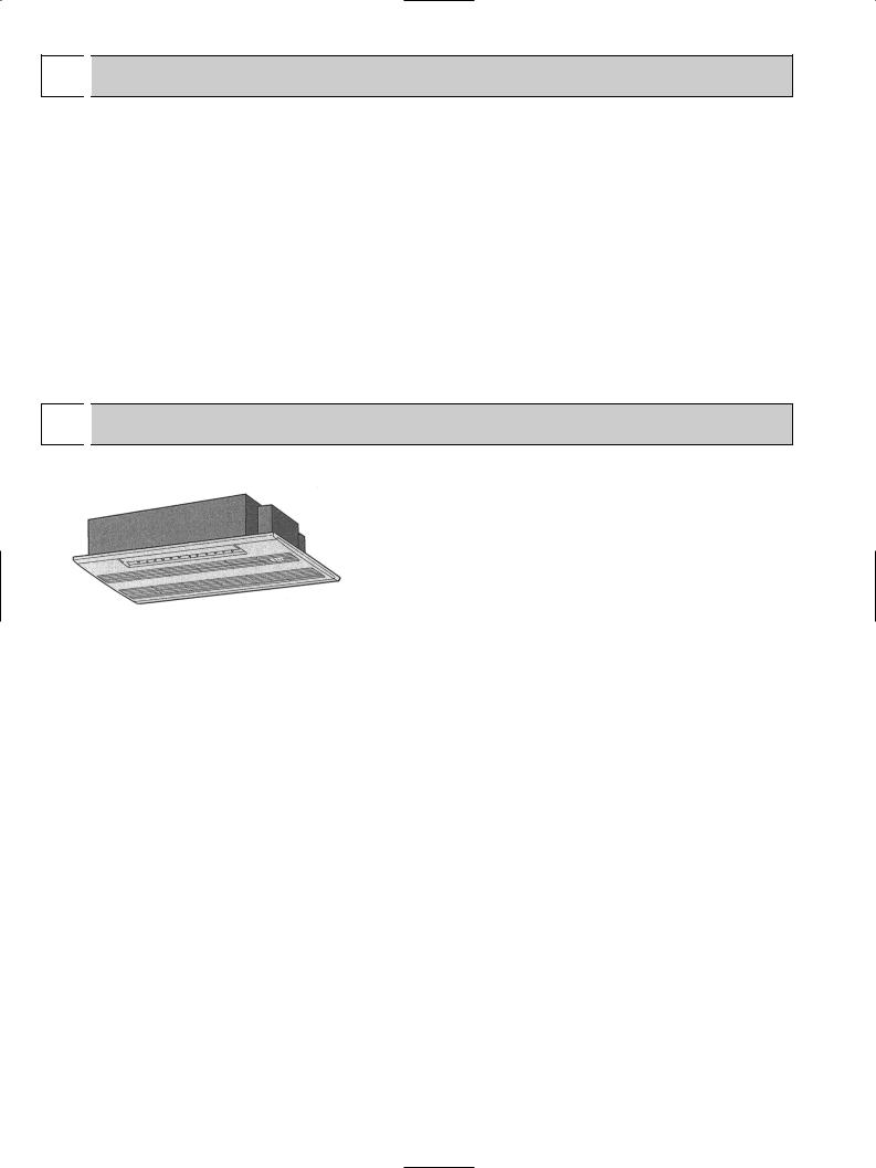
2. Light and Compact
The main unit weighs only 31 lb. and the panel merely 7 lb. This makes the PMFYseries one of the lightest in the industry. The unit size is also quite small, having been standardised to a strikingly compact 33-5/8 inch. All of this make the chore of installation and maintenance that much simpler and easier.
2
3 
 PART NAMES AND FUNCTIONS
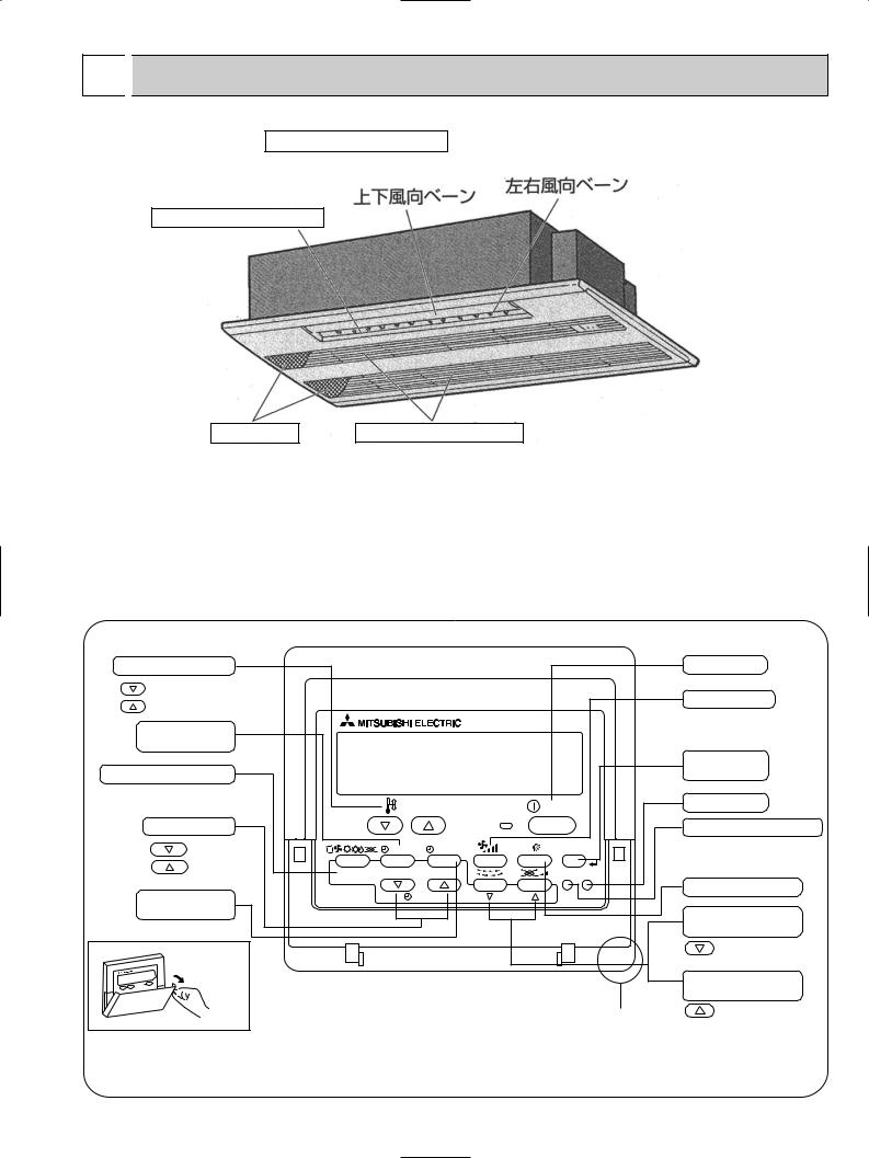
● Indoor Unit |
Auto Air Swing Vane |
|
|
|
Guide vane |
|
Disperses airflow up and |
|
|
|
down and adjusts the angle |
|
Air flow can be |
changed to horizontal |
of airflow direction. |
by moving the guide vane to the left or right. |
||
|
|
|
|
|
|
|
|
Horizontal Air Outlet
Filters |
Air intake |
Remove dust and pollutants |
Returns air from room. |
from return air. |
|
● Wired remote controller
Once the controllers are set, the same operation mode can be repeated by simply pressing the ON/OFF button.
Temperature setting buttons |
|
|
|
Down |
|
|
|
Up |
|
|
|
Timer Menu button |
|
|
|
(Monitor/Set button) |
|
|
|
Mode button (Return button) |
|
|
|
|
|
TEMP. |
|
Set Time buttons |
|
|
|
Back |
|
MENU |
ON/OFF |
Ahead |
BACK |
MONITOR/SET |
DAY |
|
|||
Timer On/Off button |
PAR-21MAA |
CLOCK |
|
(Set Day button) |
|
|
|
Opening the |
|
|
|
lid |
|
|
|
|
ON/OFF |
|
|
FILTER |
|
|
CHECK |
TEST |
OPERATION |
CLEAR |
|
Built-in temperature sensor
ON/OFF button
Fan Speed button
Filter  button (<Enter> button)
Test Run button
Check button (Clear button)
Airflow Up/Down button
Louver button
( Operation button)
To return operation number
Ventilation button
( Operation button)
To go to next operation number
3
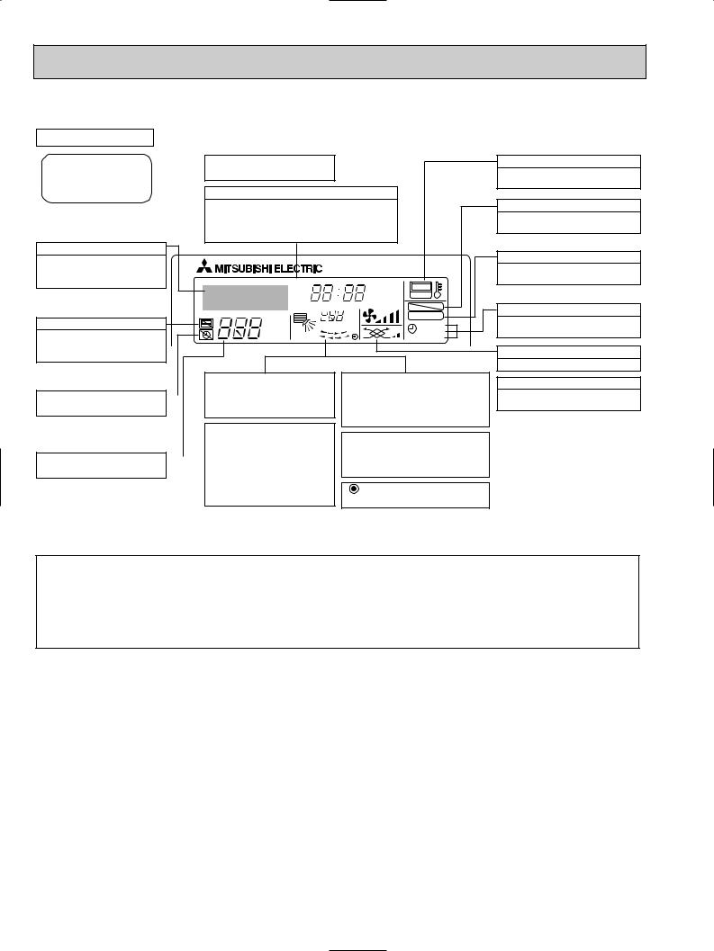
● Wired remote controller
Display Section
For purposes of this explanation, |
Day-of-Week |
all parts of the display are shown |
Shows the current day of the week. |
as lit. During actual operation, only |
|
the relevant items will be lit. |
Time/Timer Display |
Shows the current time, unless the simple or Auto Off timer is set.
If the simple or Auto Off timer is set, the time to be switched off is shown.
Identifies the current operation
Shows the operating mode, etc. *Multilanguage display is available.
|
TIME SUN MON TUE WED THU FRI SAT |
||
|
TIMER |
Hr |
ON |
|
AFTER |
AFTER |
OFF |
|
ERROR CODE |
|
FUNCTION |
|
˚F˚C |
|
FILTER |
“Centrally Controlled” indicator |
˚F˚C |
|
|
|
WEEKLY |
||
Indicates that operation from the |
ONLY1Hr. |
|
SIMPLE |
|
AUTO OFF |
||
remote controller has been prohib- |
|
|
|
ited by a master controller.
|
|
|
|
|
Up/Down Air Direction indica- |
|
Room Temperature display |
“Timer is Off” indicator |
|
|
|
|
tor |
|
Shows the room temperature. The room |
|
|
|
|
Shows the direction of the |
|
temperature display range is 46~102°F. |
|
Indicates that the timer is off. |
|
|
|
|
outcoming airflow. |
|
The display blinks if the temperature |
|
|
|
|
|
|
|
is less than 46°F or 102°F or more. |
|
|
|
|
|
“One Hour Only” indicator |
|
Louver display |
|
|
|
|
|
|
|
|
|
|
|
|
|
Displayed if the airflow is set to |
||
|
|
|
|
|
|
|
|
|
|
|
|
|
|
Indicates the action of the swing louver. |
|
Temperature Setting |
|
|
|
|
low or downward during COOL |
|
|
|
|
|
|
or DRY mode. (Operation varies |
|
Does not appear if the louver is not |
|
Shows the target temperature. |
|
|
|
|
according to model.) |
|
running. |
|
|
|
|
|
The indicator goes off in one hour, |
|
(Power On indicator) |
|
|
|
|
|
when the airflow direction also |
|
|
|
|
|
|
|
changes. |
|
Indicates that the power is on. |
“Sensor” indication
Displayed when the remote controller sensor is used.
“Locked” indicator
Indicates that remote controller buttons have been locked.
“Clean The Filter” indicator
To be displayed on when it is time to clean the filter.
Timer indicators
The indicator comes on if the corresponding timer is set.
Fan Speed indicator
Shows the selected fan speed.
Ventilation indicator
Appears when the unit is running in Ventilation mode.
Note:
●“PLEASE WAIT” message
This message is displayed for approximately 3 minutes when power is supplied to the indoor unit or when the unit is recovering from a power failure.
●“NOT AVAILABLE” message
This message is displayed if an invalid button is pressed (to operate a function that the indoor unit does not have).
If a single remote controller is used to operate multiple indoor units simultaneously that are different types, this message will not be displayed as far as any of the indoor units is equipped with the function.
4
4 

 SPECIFICATION
4-1. SPECIFICATIONS
Item
|
|
Power |
V·Hz |
|||
Cooling capacity |
Btu/h |
|||||
Heating capacity |
Btu/h |
|||||
characteristic |
|
Input |
|
Cooling |
kW |
|
|
|
|||||
|
|
|
||||
|
|
|
Heating |
|
||
|
|
|
|
|
kW |
|
Electric |
|
Current |
|
Cooling |
A |
|
|
|
Heating |
A |
|||
|
|
|
|
|
||
|
|
|
|
|
|
|
|
|
Exterior |
— |
|||
(munsell symbol) |
||||||
|
|
|
|
|
Height |
in. |
|
|
|
|
|
||
Dimensions |
|
Width |
in. |
|||
|
|
|
|
|
Depth |
in. |
Heat exchanger |
— |
|||||
n |
|
Fan No |
— |
|||
|
||||||
|
Air flow W3 |
CFM |
||||
a |
|
|||||
|
External |
|
||||
|
|
in W.G. |
||||
F |
|
static pressure |
||||
|
|
Fan motor |
kW |
|||
|
|
output |
||||
|
|
Insulator |
— |
|||
|
|
Air filter |
— |
|||
|
|
|
|
|
|
|
|
Pipe |
|
|
Gas |
[in. |
|
|
|
|
||||
|
|
|
side |
|||
dimensions |
|
|
Liquid |
[in. |
||
|
|
|
|
|
side |
|
Field drain pipe size |
[in. |
|||||
Noise level W3 |
dB |
|||||
Product weight |
lb. |
|||||
PMFY-P06NBMU-E |
PMFY-P08NBMU-E |
PMFY-P12NBMU-E |
|
PMFY-P15NBMU-E |
PMFY-P06NBMU-E1 |
PMFY-P08NBMU-E1 |
PMFY-P12NBMU-E1 |
|
PMFY-P15NBMU-E1 |
|
|
|
|
|
|
Single phase 208-230V 60Hz |
|
|
|
6,000 |
|
12,000 |
|
15,000 |
8,000 |
|
|||
6,700 |
9,000 |
13,500 |
|
17,000 |
0.042 |
0.042 |
0.044 |
|
0.054 |
0.042 |
0.042 |
0.044 |
|
0.054 |
0.20 |
0.20 |
0.21 |
|
0.26 |
0.20 |
0.20 |
0.21 |
|
0.26 |
|
|
|
|
|
Unit : Galvanized sheets · Standard grilles : ABS resin acrylic coating |
Munsell<6.4Y 8.9/0.4> |
||
|
9-1/16<1-3/16> |
|
|
|
31-15/16<39-3/8> |
|
|
|
15-9/16<18-1/2> |
|
|
|
Cross fin |
|
|
|
Line flow fan 1 |
|
|
230-250-280-300 |
|
|
|
250-280-300-320 |
|
270-300-340-370 |
|
|
|
|
|
|
0 |
|
|
0.028
Polyethylene sheet
PP honey comb fabric
1/2"
1/4"
1" O.D. (PVC pipe VP-20 connectable)
27-30-33-35 |
32-34-36-37 |
33-35-37-39 |
|
|
|
31<7>
Note 1. |
Rating conditions |
|
|
|
Cooling: Indoor: |
D.B. 80°F |
W.B. 67°F |
|
outdoor: D.B. 95°F |
W.B. 75°F |
|
|
Heating: Indoor: |
D.B. 70°F |
|
|
outdoor: D.B. 47°F |
W.B. 43°F |
|
Note 2. |
The number indicated in < > is for the grille. |
||
W 3. Air flow and the noise level are indicated as Low - Medium2 - Medium1 - High.
5
4-2. ELECTRICAL PARTS SPECIFICATIONS
Service Ref.
PMFY-P06NBMU-E PMFY-P08NBMU-E PMFY-P12NBMU-E PMFY-P15NBMU-E Symbol PMFY-P06NBMU-E1 PMFY-P08NBMU-E1 PMFY-P12NBMU-E1 PMFY-P15NBMU-E1
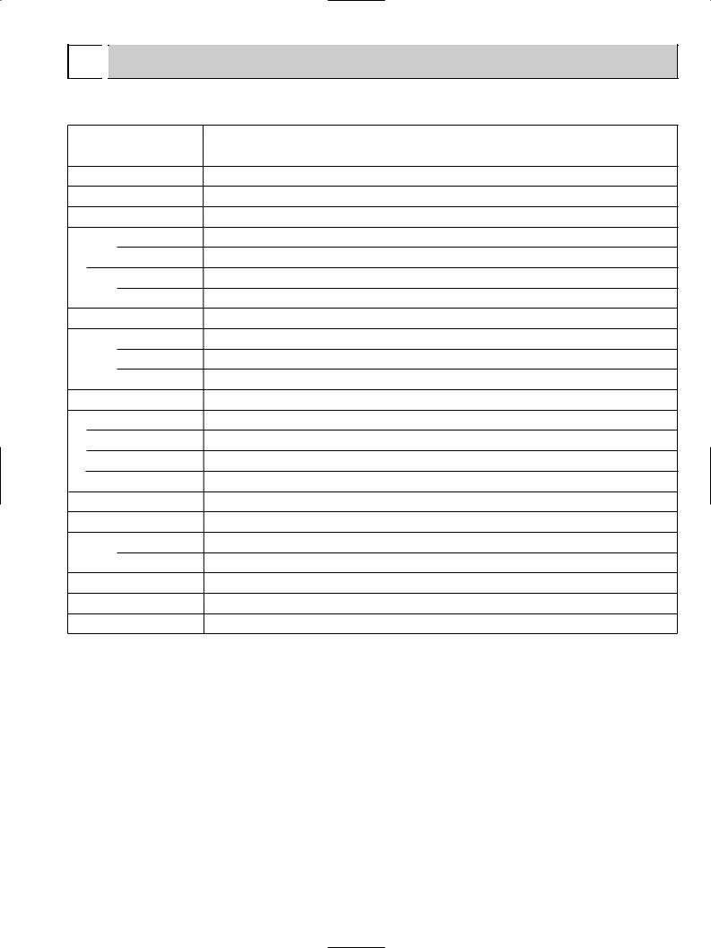
Parts name
Room temperature thermistor
Liquid pipe thermistor
Gas pipe thermistor
Fuse
(Indoor controller board)
Fan motor
Vane motor
Drain pump
Drain sensor
Linear expansion valve
Power supply terminal block
Transmission terminal block
MA-remote controller terminal block
TH21
TH22
TH23
FUSE
MF
MV
DP
DS
LEV
TB2
TB5
TB15
Resistance 30˚F/15.8k", 50˚F/9.6k", 70˚F/6.0k", 80˚F/4.8k", 90˚F/3.9k", 100˚F/3.2k"
Resistance 30˚F/15.8k", 50˚F/9.6k", 70˚F/6.0k", 80˚F/4.8k", 90˚F/3.9k", 100˚F/3.2k"
Resistance 30˚F/15.8k", 50˚F/9.6k", 70˚F/6.0k", 80˚F/4.8k", 90˚F/3.9k", 100˚F/3.2k"
250V 6A
DC Brushless Motor
8-pole OUTPUT 28W
PN0H28-MB
MSFJC 20M23 12V/380"
PJV-1063 208-240V 50/60Hz
Thermistor resistance 30_F/6.3k", 50_F/3.9k", 70_F/2.5k", 80_F/2.0k", 90_F/1.6k", 100_F/1.3k"
DC12V Stepping motor drive port dimension [3.2 (0~2000pulse)
EDM-40YGME
(L1, L2, GR) Rated to 330V 30A w
(M1, M2, S) Rated to 250V 20A w
(1,2) Rated to 250V 10A w
wNote : Refer to WIRING DIAGRAM for the supplied voltage.
6
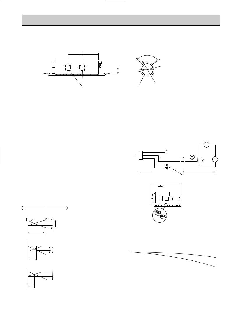
4-3. AIR CAPACITY TAKEN FROM OUTSIDE
PMFY-P·NBMU-E series are capable of taking air from outside. When taking air from outside, the duct fan is used. The air capacity should be 20% or less of the airflow SPEC(Hi).
9-13/16 |
11-3/8 |
90- |
|
|
|
|
|
|
4-{1/8 |
|
|
|
|
15/16 |
|
|
|
3- |
|
|
|
|
{ |
|
|
|
4-1/4 |
|
|
|
|
|
{ |
|
|
|
|
4 |
|
|
|
|
- |
|
|
|
|
13/16 |
|
|
Fresh air intake hole |
Fresh air intake hole |
|
(Unit:inch) |
|
(Knockout) |
(Knockout) |
|
|
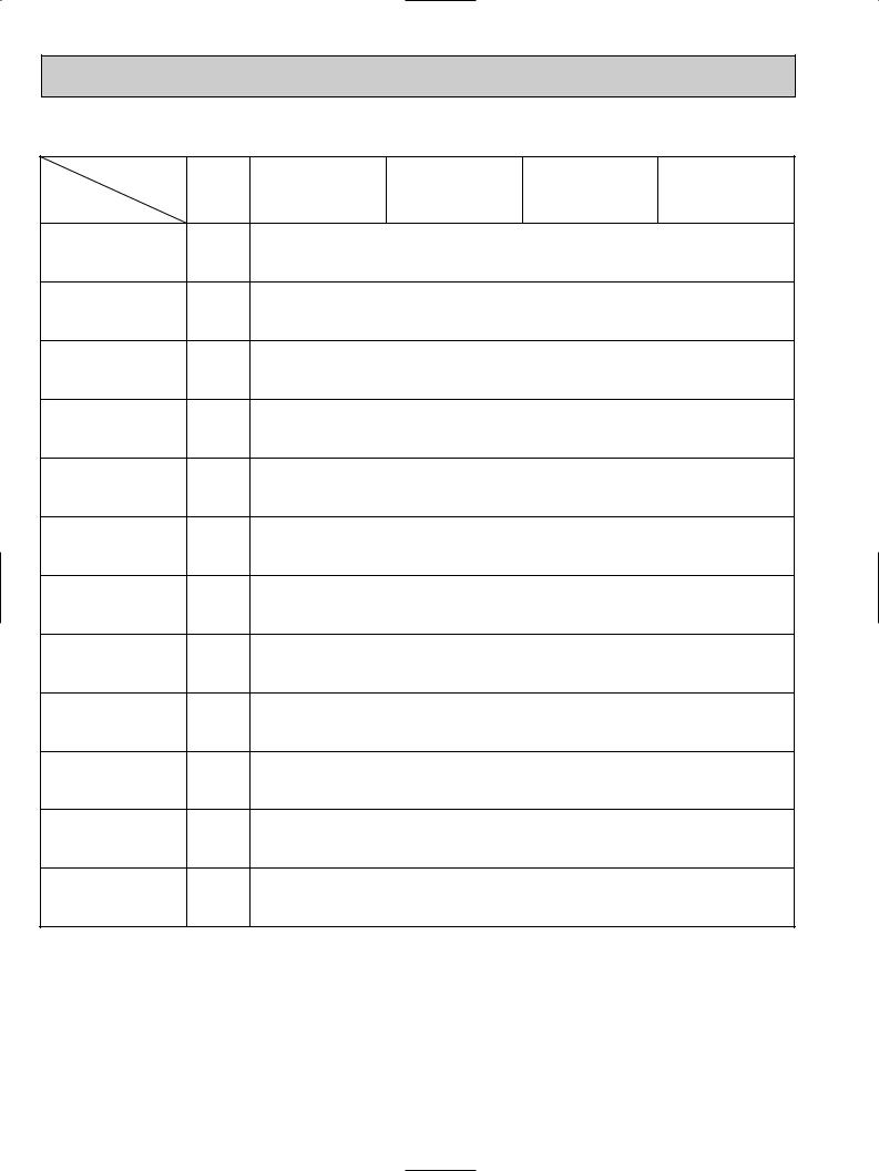
Service Ref. |
Air flow (Hi) |
Air capacity taken from outside |
|
|
|
|
|
PMFY-P06NBMU-E |
300 CFM |
60 CFM |
|
PMFY-P06NBMU-E1 |
|||
|
|
||
PMFY-P08NBMU-E |
320 CFM |
64 CFM |
|
PMFY-P08NBMU-E1 |
|||
|
|
||
PMFY-P12NBMU-E |
320 CFM |
64 CFM |
|
PMFY-P12NBMU-E1 |
|||
|
|
||
PMFY-P15NBMU-E |
370 CFM |
74 CFM |
|
PMFY-P15NBMU-E1 |
|||
|
|
Operation in conjunction with duct fan (Booster fan)
●Whenever the indoor unit is operating, the duct fan operates.
(1)Connect the optional multiple remote controller adaptor (PAC-SA88HA-E) to the connector CN51 on the indoor controller board.
(2)Drive the relay after connecting the 12V DC relay between the Yellow and Orange connector lines.
(w)Use a relay of 1W or smaller.
MB: Electromagnetic switch power relay for duct fan. X: Auxiliary relay (12V DC LY-1F)
|
How to read curves |
|
|
|
||
|
Curve in the |
Duct characteristics |
|
|
|
|
1 |
at site |
|
|
|
|
|
|
right graphs |
|
|
|
|
|
0 |
|
A |
C |
Q…Designed amount |
of |
fresh air |
|
|
|||||
|
|
|
|
intake |
|
<CFM> |
|
Q |
B |
|
A…Static pressure loss |
of fresh air |
|
|
|
|
||||
|
|
|
intake duct system with air flow |
|||
|
|
|
|
|||
|
|
|
|
amount Q |
|
<in. W.G> |
2 |
|
|
|
B…Forced static pressure at air condi- |
||
|
|
|
tioner inlet with air flow amount Q |
|||
|
|
|
|
|||
|
|
C A |
|
|
|
<in. W.G> |
|
|
|
|
C…Static pressure of booster fan with |
||
|
|
E |
|
air flow amount Q |
|
<in. W.G> |
|
Q |
|
|
D…Static pressure loss |
increase |
|
|
|
|
amount of fresh air intake duct |
|||
|
|
|
|
|||
|
|
|
|
system for air flow amount Q |
||
3 |
|
|
|
|
|
<in. W.G> |
|
|
|
E…Static pressure of indoor unit with |
|||
|
|
D |
|
|||
|
|
|
air flow amount Q |
|
<in. W.G> |
|
|
|
|
|
|
||
|
|
|
|
Qa…Estimated amount of fresh air |
||
|
|
A |
|
intake without D |
|
<CFM> |
|
Q |
|
|
|
|
|
|
Qa |
|
|
|
|
|
|
|
|
Be sure to secure insulation |
~ |
|
|
|
|
|
||
|
|
|
material by tape, etc. |
|
|
CN51 |
5 |
Green |
|
|
|
on |
|
|
Yellow |
|
|
indoor unit |
|
|
|
|
|
1 |
|
Orange |
|
MB |
|
board |
|
|
|||
|
Connector (5P) |
Red |
|
|
|
|
|
|
|
|
|
|
Indoor unit side |
Brown |
Installation at site |
||
|
Multiple remote |
||||
|
|
|
|||
|
|
|
|
|
|
|
|
|
controller adapter |
Be sure to secure insulation |
|
|
|
|
PAC-SA88HA-E |
material by tape, etc. |
|
Indoor controller board
Distance between indoor controller board and relay must be within 33 feet.
Multiple remote controller adapter PAC-SA88HA-E
CN51
Characteristic diagram of air capacity taken from outside of PMFY-P·NBMU-E
|
0.2 |
|
|
|
|
|
|
|
|
|
|
|
|
|
|
|
|
|
|
|
|
|
|
|
|
|
|
|
|
|
|
|
|
|
|
|
|
(in.W.G.) |
0.1 |
|
|
|
|
|
|
|
|
|
|
|
|
|
|
|
|
|
|
|
|
|
|
|
|
|
|
|
|
|
|
|
|
|
|
||
00 |
|
|
|
|
|
|
|
|
|
|
|
|
|
|
|
|
|
|
pressure |
|
|
|
|
|
|
|
|
|
|
|
|
|
|
2 intake |
|
||
|
|
|
|
|
|
|
|
|
|
|
|
|
|
|
|
|||
-0.1 |
|
|
|
|
|
|
|
|
|
|
|
|
|
|
|
|
|
|
|
|
|
|
|
|
|
|
|
|
|
|
|
|
|
1 intake |
|
||
|
|
|
|
|
|
|
|
|
|
|
|
|
|
|
|
|
||
Static |
-0.2 |
|
|
|
|
|
|
|
|
|
|
|
|
|
|
|
|
|
|
|
|
|
|
|
|
|
|
|
|
|
|
|
|
|
|
||
-0.3 |
|
|
|
|
|
|
|
|
|
|
|
|
|
|
|
|
|
|
|
|
|
|
|
|
|
|
|
|
|
|
|
|
|
|
|
|
|
|
-0.4 |
|
|
|
|
|
|
|
|
|
|
|
|
|
|
|
|
|
|
|
|
|
|
|
|
|
|
|
|
|
|
|
|
|
|
|
|
|
0 |
10 |
20 |
30 |
40 |
50 |
60 |
70 |
80 |
|||||||||
Air flow (CFM)
7

4-4. NOISE CRITERION CURVES
PMFY-P06NBMU-E |
|
NOTCH |
SPL(dB) |
LINE |
|||||
PMFY-P06NBMU-E1 |
|
High |
35 |
|
|||||
|
Medium1 |
33 |
|
||||||
|
|
|
|
|
|
||||
|
|
|
|
|
Medium2 |
30 |
|
||
|
|
|
|
|
Low |
27 |
|
||
bar) |
90 |
|
|
|
|
|
|
|
|
|
|
|
|
|
|
|
|
||
dB = 0.0002 |
80 |
|
|
|
|
|
|
|
|
70 |
|
|
|
|
|
|
NC-70 |
||
dB (0 |
|
|
|
|
|
|
|
||
|
|
|
|
|
|
|
|
||
LEVEL, |
60 |
|
|
|
|
|
|
|
|
|
|
|
|
|
|
|
NC-60 |
||
|
|
|
|
|
|
|
|
||
PRESSURE |
50 |
|
|
|
|
|
|
|
|
|
|
|
|
|
|
|
NC-50 |
||
40 |
|
|
|
|
|
|
|
||
|
|
|
|
|
|
|
NC-40 |
||
SOUND |
|
|
|
|
|
|
|
||
30 |
|
|
|
|
|
|
|
||
BAND |
|
|
|
|
|
|
|
NC-30 |
|
20 |
|
|
|
|
|
|
|
||
OCTAVE |
|
|
|
|
|
|
|
||
|
|
|
|
|
|
|
NC-20 |
||
APPROXIMATE THRESHOLD OF HEARING |
|
|
|
|
|||||
FOR CONTINUOUS NOISE |
|
|
|
|
|
|
|||
10 |
125 |
250 |
500 |
1000 |
2000 |
4000 |
8000 |
||
|
|||||||||
|
63 |
||||||||
BAND CENTER FREQUENCIES, Hz
PMFY-P15NBMU-E |
|
NOTCH |
SPL(dB) |
LINE |
||||||
PMFY-P15NBMU-E1 |
|
High |
39 |
|
||||||
|
Medium1 |
37 |
|
|||||||
|
|
|
|
|
|
|
||||
|
|
|
|
|
|
Medium2 |
35 |
|
||
|
|
|
|
|
|
Low |
33 |
|
||
bar) |
90 |
|
|
|
|
|
|
|
|
|
|
|
|
|
|
|
|
|
|
||
dB = 0.0002 |
80 |
|
|
|
|
|
|
|
|
|
70 |
|
|
|
|
|
|
|
NC-70 |
||
dB (0 |
|
|
|
|
|
|
|
|
||
|
|
|
|
|
|
|
|
|
||
LEVEL, |
60 |
|
|
|
|
|
|
|
|
|
|
|
|
|
|
|
|
|
NC-60 |
||
|
|
|
|
|
|
|
|
|
||
PRESSURE |
50 |
|
|
|
|
|
|
|
|
|
|
|
|
|
|
|
|
|
NC-50 |
||
40 |
|
|
|
|
|
|
|
|
||
|
|
|
|
|
|
|
|
NC-40 |
||
SOUND |
|
|
|
|
|
|
|
|
||
30 |
|
|
|
|
|
|
|
|
||
|
|
|
|
|
|
|
|
NC-30 |
||
BAND |
|
|
|
|
|
|
|
|
||
20 |
APPROXIMATE |
|
|
|
|
|
|
|||
OCTAVE |
|
|
|
|
|
|
||||
|
THRESHOLD OF |
|
|
|
|
|
|
|||
|
HEARING FOR |
|
|
|
|
|
NC-20 |
|||
|
CONTINUOUS |
|
|
|
|
|
|
|||
10 |
NOISE |
|
|
|
|
|
|
|
||
63 |
125 |
250 |
500 |
1000 |
2000 |
4000 |
8000 |
|||
|
||||||||||
|
|
|||||||||
BAND CENTER FREQUENCIES, Hz
PMFY-P08NBMU-E |
|
NOTCH |
SPL(dB) |
LINE |
||||||
PMFY-P12NBMU-E |
|
High |
37 |
|
||||||
|
Medium1 |
36 |
|
|||||||
PMFY-P08NBMU-E1 |
|
|
||||||||
|
Medium2 |
34 |
|
|||||||
PMFY-P12NBMU-E1 |
|
Low |
32 |
|
||||||
|
|
|
|
|
||||||
bar) |
90 |
|
|
|
|
|
|
|
|
|
|
|
|
|
|
|
|
|
|
||
dB = 0.0002 |
80 |
|
|
|
|
|
|
|
|
|
70 |
|
|
|
|
|
|
|
NC-70 |
||
dB (0 |
|
|
|
|
|
|
|
|
||
|
|
|
|
|
|
|
|
|
||
LEVEL, |
60 |
|
|
|
|
|
|
|
|
|
|
|
|
|
|
|
|
|
NC-60 |
||
|
|
|
|
|
|
|
|
|
||
PRESSURE |
50 |
|
|
|
|
|
|
|
|
|
|
|
|
|
|
|
|
|
NC-50 |
||
40 |
|
|
|
|
|
|
|
|
||
|
|
|
|
|
|
|
|
NC-40 |
||
SOUND |
|
|
|
|
|
|
|
|
||
30 |
|
|
|
|
|
|
|
|
||
BAND |
|
|
|
|
|
|
|
|
NC-30 |
|
20 |
APPROXIMATE |
|
|
|
|
|
|
|||
OCTAVE |
|
|
|
|
|
|
||||
|
THRESHOLD OF |
|
|
|
|
|
|
|||
|
HEARING FOR |
|
|
|
|
|
NC-20 |
|||
|
CONTINUOUS |
|
|
|
|
|
|
|||
10 |
NOISE |
|
|
|
|
|
|
|
||
63 |
125 |
250 |
500 |
1000 |
2000 |
4000 |
8000 |
|||
|
||||||||||
|
|
|||||||||
BAND CENTER FREQUENCIES, Hz
UNIT
CEILING
5ft
MICROPHONE
8

5 OUTLINES AND DIMENSIONS
PMFY-P06NBMU-E PMFY-P06NBMU-E1 PMFY-P08NBMU-E PMFY-P08NBMU-E1 PMFY-P12NBMU-E PMFY-P12NBMU-E1 PMFY-P15NBMU-E PMFY-P15NBMU-E1
coverPipe O.D.{1-11/16({43) Refrigerant |
piping |
pipingDrainagePVC pipe:VP-20[I.D.{31/32"({25)] |
ofDetailsfresh air intake hole |
90- |
4-{1/8(2.8) Burring hole |
|
|
Knockout |
9-13/16(250) 11-3/8(288.5) supplypowerforblockTerminal |
{ { 6.35) 1/4"( O.D. |
{ { 12.7) 1/2"( O.D. |
|
|
|
|
100) |
|
|
|
|
|
|
|
|
|
15/16( |
|
-13/6(122) |
|
|
|
|
|
|
|
- |
|
|
|
|
|
|
|
|
|
3 |
|
|
|
|
|
|
|
|
|
{ |
4 |
|
|
|
|
|
|
|
|
|
{ |
|
|
Liquidpipe |
Gaspipe |
|
|
|
|
|
|
|
|
(108) 4-1/4
Fresh air intake hole
Right side |
Terminal block for transmission |
Unit : in. (mm)
unit |
|
|
plate |
|
(110) |
Mounting |
|
|
|
4-5/16 |
|
indoor |
(235)ormore |
|
|
9-1/2 |
|
|
|
|
|
|
|
|
9-1/16(230) |
|
|
Installation space required around |
(110) |
4-5/16 |
|
Suspension bolt(M10 or W 3/8) |
Panel(grille):PMP-16BMU |
|
13/16(20) |
2-15/18(74.5) |
1-1/32(26) |
|
|
9-3/8(247) |
|
Outerline of grille |
lineof unit |
|
|
|
Electricalbox |
ofside3/8(1000)outer-39grille openingceiling16(960)-13-37 |
boltsuspension15/18(811)-31 pitch |
|
13/16(20)13/16(20) |
|
2-11/16(69) |
|
|
|
15/16(812)-31 |
|
||
7/8(759)-29 |
2-1/16(53) |
|
|
outlet(lower)Air |
Center |
|
|
7/8(759)-29 |
||||
|
15/18(74.5)-2 |
|
|
.11/16(175).11/16(175) |
|
|
|
|
|
pipeDrainage |
pipe:PVC 20[O.D.-VP {1"(26)] |
|
Top |
1/32(26)-1 |
|
13/18(46)-1 |
11/16(43)-1 |
|
|
|
|
|
|||
13/16(20) |
|
1-25/32(45) |
|
1-25/32(45) |
|
|
|
|
||||
|
|
|
|
|
|
|
|
|
|
|||
|
|
13/16(20) |
|
|
|
13/16(20) |
|
|
|
|
||
|
|
|
|
Suspensionboltpitch |
13-3/8(340) |
|
|
|
|
|||
|
|
|
|
Ceilingopening |
|
16-15/16(430) |
11-7/8(302) |
10(254) |
5-9/16(141) |
|||
|
|
|
|
Outersideofgrille |
|
|
pipe(gas)Refrigerant |
{1/2"(12.7)O.D. 15-9/16(395) |
||||
|
|
|
|
|
18-1/2(470) |
|
|
|
|
|||
|
|
Terminal block for |
remote controller |
|
|
{1-31/32(50) |
|
|
|
1-9/16(40) |
|
3/16(56) |
Front |
|
outer3/8(1000)- side of grille |
5/8(600)-23 7-7/8(200) |
|
|
|
drainpan |
|
|
|
|
2- |
|
|
39 |
7/8(200)-7 |
9-1/16(230) |
13/16(20) |
|
|
|
|
7-13/16(198) |
13/32(10) |
|
|
|
|
|
|
|
3-3/8(96) |
|
|
6-15/16(176) |
|
Refrigerant |
pipe(liquid) O.D.{1/4"(6.35) |
Ceilingpanel |
Leftside |
3-3/8(96) |
|
|
|
|
|
|
1-3/16(30) |
Outersideofgrille |
18-1/2(470) |
2-3/8(60) |
Panel(grille):PMP-16BMU |
|
|
|
Lower view |
Ceiling panel |
|
pan |
Same line |
Drain |
|
9
10
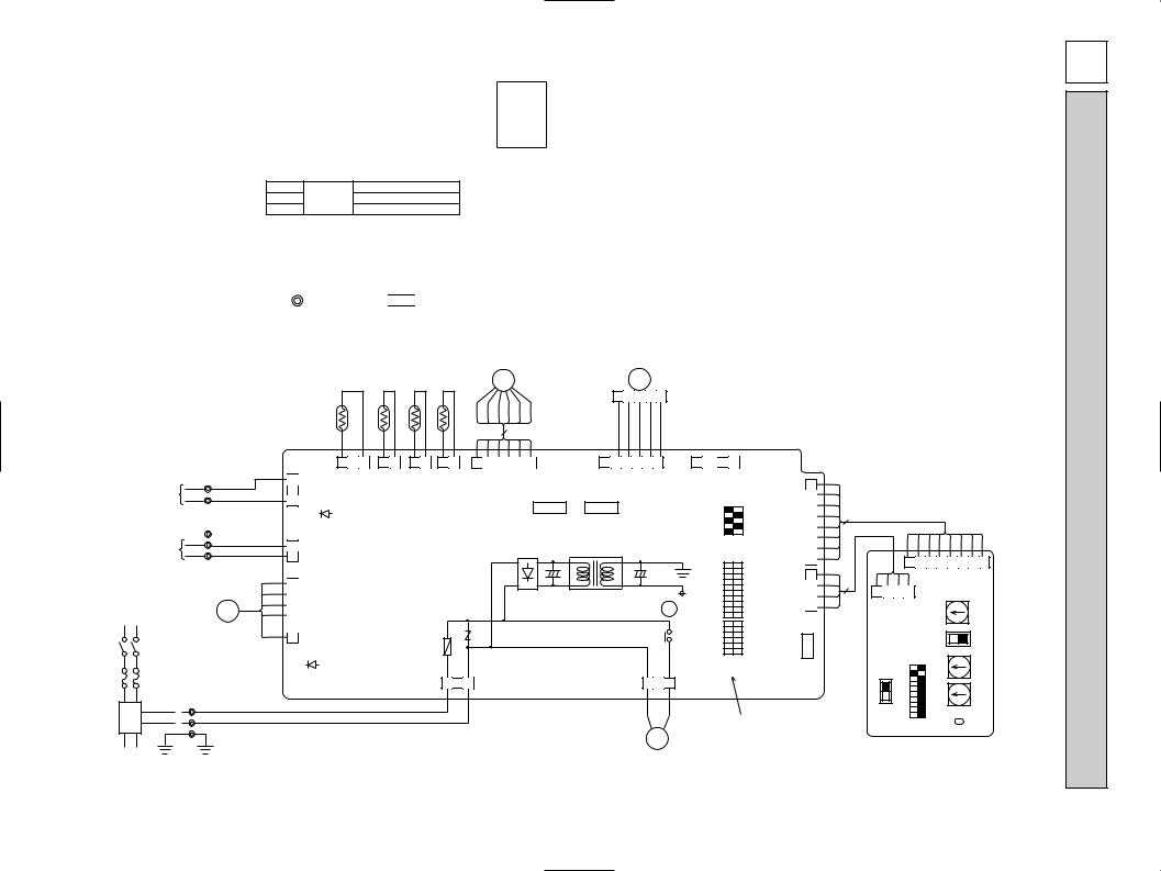
[Legend]
Symbol |
|
Name |
Symbol |
|
Name |
Symbol |
|
Name |
|||
I.B |
Indoor controller board |
|
X1 |
Aux.relay |
Drain pump |
TH21 |
Thermistor |
Room temp. detection |
|||
|
CN25 |
Connector |
Humidifier |
|
T |
Transformer |
|
|
|
|
(32°F/15k", 77°F/5.4k") |
|
CN27 |
|
Damper |
|
LED1 |
Power supply (I.B) |
TH22 |
|
Pipe temp. detection / Liquid |
||
|
CN32 |
|
Remote switch |
|
LED2 |
Power supply (I.B) |
|
|
|
(32°F/15k", 77°F/5.4k") |
|
|
CN51 |
|
Centrally control |
MF |
Fan motor (with inner thermo) |
TH23 |
|
Pipe temp. detection / Gas |
|||
|
CN52 |
|
Remote Indication |
MV |
Vane motor |
|
|
|
|
(32°F1/15k", 77°F/5.4k") |
|
|
SW2 |
Switch |
Capacity code |
DP |
Drain water lifting-up mech. |
A.B |
Address board |
|
|||
|
SW3 |
|
Mode selection |
DS |
Drain sensor |
|
|
SW1 |
Switch |
Mode selection |
|
|
SW4 |
|
Model selection |
LEV |
Linear expansion valve |
|
SW5 |
|
Voltage selection |
||
|
ZNR |
Varistor |
|
TB2 |
Terminal |
Power supply |
|
SW11 |
|
Address setting 1st digit |
|
|
FUSE |
Fuse (6A / 250V) |
TB5 |
block |
Transmission |
|
SW12 |
|
Address setting 2nd digit |
||
|
|
|
|
TB15 |
|
MA-Remote Controller |
|
SW14 |
|
Connection No. |
|
Note
1.At servicing for outdoor unit, always follow the wiring diagram of outdoor unit.
2.In case of using MA-Remote controller, please connect to TB15. (Remote controller wire is non-polar.) 3.In case of using M-NET, please connect to TB5. (Transmission wire is non-polar.)
4.Symbol [S] of TB5 is the shield wire connection.
5.Symbols used in wiring diagram above are, : terminal block, 


 :connecter.
6.The setting of the SW2, SW3 dip switches differs in the capacity for the detail, refer to the fig : w1. 7.Please set the switch SW5 according to the power supply voltage.
LED on indoor board for service
Mark |
Meaning |
Function |
|
LED1 |
Main power supply |
Main power supply (Indoor unit:208-230V) |
|
Power on Lamp is lit. |
|||
|
|
||
LED2 |
Power supply for |
Power supply for MA-Remote controller |
|
MA-Remote controller |
on Lamp is lit. |
<fig : w1>
Models |
|
SW2 |
|
SW3 |
|||||||||||
P06 |
ON |
|
|
|
|
|
ON |
|
|
|
|
|
|
|
|
OFF |
|
|
|
|
|
OFF |
|
|
|
|
|
|
|
|
|
|
1 2 3 4 5 6 |
|
1 2 3 4 5 6 7 8 910 |
||||||||||||
P08 |
ON |
|
|
ON |
|
|
|
|
|
|
|
|
|||
OFF |
|
|
|
|
|
OFF |
|
|
|
|
|
|
|
|
|
|
1 2 3 4 5 6 |
|
1 2 3 4 5 6 7 8 910 |
||||||||||||
|
|
|
|
|
|
|
|
|
|
|
|
||||
P12 |
ON |
|
|
|
|
|
ON |
|
|
|
|
|
|
|
|
OFF |
|
|
|
|
|
OFF |
|
|
|
|
|
|
|
|
|
|
1 2 3 4 5 6 |
|
1 2 3 4 5 6 7 8 910 |
||||||||||||
|
|
|
|
|
|
|
|
|
|
|
|
||||
P15 |
ON |
|
|
|
|
|
ON |
|
|
|
|
|
|
|
|
OFF |
|
|
|
|
|
OFF |
|
|
|
|
|
|
|
|
|
|
1 2 3 4 5 6 |
|
1 2 3 4 5 6 7 8 910 |
||||||||||||
(w2)Use copper supply wire.
TO MA-REMOTE |
TB15 |
1 |
CONTROLLER |
2 |
|
DC8.7-13V |
||
|
|
|
|
DS |
|
I.B |
|
|
|
|
|
3 2 1 |
ORN |
1 |
|
(WHT) |
|
CN3A |
DRAIN |
|
ORN |
2 |
(BLU) |
CN31 |
3 |
|
|
|
|
|
|
|
TO OUTDOOR UNIT |
S(SHIELD) |
TB5 |
|
M2 |
BLU |
||
BC CONTROLLER |
|||
M1 |
BLU |
||
REMOTE CONTROLLER |
|||
DC24-30V |
|
|
POWER SUPPLY |
5 |
|
MF |
||
~ / N 208—230V 60Hz |
BREAKER (15A)
LED2
1 |
(BLU) |
(M-NET) |
|
2 |
CN2M |
6 |
|
5 |
|
4 |
FAN |
3 |
(WHT) |
2 |
1 |
FUSE(15A) |
|
LED1 |
|
|
|
||
<w2> |
L1 TB2 |
RED |
|
PULL BOX |
|||
L2 |
BLU |
||
|
|||
|
G |
GRN / YLW |
|
|
|
||
TO NEXT INDOOR UNIT |
|
|
TH23 TH22 TH21
2 1 |
2 1 |
2 1 |
(BLK) (WHT) (RED) GAS LIQUID INTAKE CN29 CN21 CN20
LEV MV
1 2 3 4 5
BLU BRN ORN YLW RED |
WHT |
|
BRN |
RED ORN YLW GRN |
6 |
|
|
||
|
|
|
|
|
6 5 4 3 2 1 |
|
6 5 4 3 2 1 |
||
(WHT) |
|
|
|
(GRN) |
LEV |
|
|
|
VANE |
CN60 |
|
|
|
CN6V |
|
5 |
1 |
5 |
1 |
|
(WHT) |
|
(GRN) |
|
|
CENTRALLY |
REMOTE |
|
|
|
CONTROL |
|
INDICATION |
|
|
CN51 |
|
CN52 |
|
2 1 
 2 1
2 1
CN25 CN27
|
ON OFF |
SW4 |
2 34 5 |
|
1 |
|
|
T |
X1 |
SW3 |
3 45 6 7 8 910 |
|
|
|
|
2 |
|
|
|
|
|
|
1 |
|
|
|
|
SW2 |
6 |
FUSE |
|
|
X1 |
324 5 |
|
250V |
|
|
|
|
1 |
6A |
|
|
|
|
|
|
|
|
|
ON OFF |
|
CND |
|
|
|
(WHT) |
|
3 2 |
1 |
1 2 3 |
|
||
(RED) |
CNP |
|
|
8 |
|
|
7 |
|
(RED) |
6 |
|
5 |
||
ADDRESS |
||
CN81 |
4 |
|
|
3 |
|
|
2 |
|
|
1 |
|
(RED) |
4 |
|
3 |
||
ADDRESS |
2 |
|
CN42 |
1 |
|
|
(WHT) 1 REMOTE SWITCH
CN32
3
See fig : w1
DP
8
A.B
8 |
7 6 5 4 3 2 1 |
|
4 |
(RED) |
|
ADDRESS |
CONNECTION No. |
|
4 3 2 1 |
SW14SWC |
|
CN82 |
|
|
(RED)
ADDRESS |
0 |
|
|
CN43 |
|
SW5 |
230V208V |
SW1 |
ON |
OFF |
67891045312 |
SW11SW12 |
2 |
1 |
DIGITDIGITDIGIT |
0 |
1ST2ND3RD |
||||||||
|
|
|
|
|
|
|
0 |
|
|
E-P15NBMU-PMFY E-P12NBMU-PMFY E-P08NBMU-PMFY E-P06NBMU-PMFY
DIAGRAM WIRING 6
11
[Legend]
Symbol |
|
Name |
Symbol |
|
Name |
Symbol |
|
|
Name |
|||
I.B |
Indoor controller board |
|
X1 |
Aux.relay |
Drain pump |
TH21 |
Thermistor |
|
Room temp. detection |
|||
|
CN25 |
Connector |
Humidifier |
|
T |
Transformer |
|
|
|
|
|
(32°F/15kΩ , 77°F/5.4kΩ ) |
|
CN27 |
|
Damper |
|
LED1 |
Power supply(I.B) |
TH22 |
|
|
Pipe temp. detection / Liquid |
||
|
CN32 |
|
Remote switch |
|
LED2 |
Power supply(I.B) |
|
|
|
|
(32°F/15kΩ , 77°F/5.4kΩ ) |
|
|
CN51 |
|
Centrally control |
MF |
Fan motor |
|
TH23 |
|
|
Pipe temp. detection / Gas |
||
|
CN52 |
|
Remote Indication |
MV |
Vane motor |
|
|
|
|
|
(32°F/15kΩ , 77°F/5.4kΩ ) |
|
|
SW2 |
Switch |
Capacity code |
DP |
Drain water lifting-up mech. |
A.B |
Address board |
|
||||
|
SW3 |
|
Mode selection |
DS |
Drain sensor |
|
|
SW1 |
Switch |
|
Mode selection |
|
|
SW4 |
|
Model selection |
LEV |
Linear expansion valve |
|
SW5 |
|
|
Voltage selection |
||
|
ZNR |
Varistor |
|
TB2 |
Terminal |
Power supply |
|
SW11 |
|
|
Address setting 1st digit |
|
|
FUSE |
Fuse (6A / 250V) |
TB5 |
block |
Transmission |
|
SW12 |
|
|
Address setting 2nd digit |
||
|
|
|
|
TB15 |
|
MA-Remote Controller |
|
SW14 |
|
|
Connection No. |
|
LED on indoor board for service
Mark |
Meaning |
|
|
|
|
Function |
LED1 |
Main power supply |
Main power supply (Indoor unit:208-230V) |
||||
Power on |
|
Lamp is lit. |
||||
|
|
|
||||
LED2 |
Power supply for |
Power supply for MA-Remote controller |
||||
MA-Remote controller |
on |
|
Lamp is lit. |
|||
|
|
|||||
Note |
|
|
|
|
|
|
|
|
|
|
|
|
|
|
|
|
|
|
|
|
|
1.At servicing for outdoor unit, always follow the wiring diagram of outdoor unit. |
|
<fig:w1> |
|
|
|
|
|
|
|
|
|
|
|
|
|
|
|
|
|||
2.In case of using MA-Remote controller, please connect to TB15. (Remote controller wire is non-polar.) |
|
|
|
|
|
|
|
|
|
|
|
|
|
|
|
|
|
|
|
||
|
|
Models |
|
SW2 |
|
|
|
SW3 |
|||||||||||||
3.In case of using M-NET, please connect to TB5. (Transmission line is non-polar.) |
|
|
P06 |
ON |
|
|
|
ON |
|
|
|
|
|
|
|
|
|
|
|
||
|
|
|
|
|
|
|
|
|
|
|
|
|
|
|
|
||||||
|
|
|
|
|
OFF |
|
|
|
OFF |
|
|
|
|
|
|
|
|
|
|
|
|
4.Symbol [S]of TB5 is the shield wire connection. |
|
|
|
|
|
1 2 3 4 5 6 |
|
1 2 3 4 5 6 7 8 910 |
|||||||||||||
|
|
|
|
P08 |
ON |
|
|
|
ON |
|
|
|
|
|
|
|
|
|
|
|
|
5.Symbols used in wiring diagram above are, |
: terminal block, |
:connector. |
|
|
OFF |
|
|
|
OFF |
|
|
|
|
|
|
|
|
|
|
|
|
|
|
|
|
|
|
1 2 3 4 5 6 |
|
1 2 3 4 5 6 7 8 910 |
|||||||||||||
6.The setting of the SW2, SW3 dip switches differs in the capacity for the detail, refer to the fig :w1. |
|
|
|
|
|
|
|
|
|
|
|
|
|
|
|
|
|
|
|||
|
|
P12 |
ON |
|
|
|
ON |
|
|
|
|
|
|
|
|
|
|
|
|||
7.Please set the switch SW5 according to the power supply voltage. |
|
|
|
OFF |
|
|
|
OFF |
|
|
|
|
|
|
|
|
|
|
|
||
|
|
|
|
1 2 3 4 5 6 |
|
1 2 3 4 5 6 7 8 910 |
|||||||||||||||
|
|
|
|
|
|
|
|
|
|
|
|
|
|
|
|
|
|
|
|
||
|
|
|
|
|
P15 |
ON |
|
|
|
ON |
|
|
|
|
|
|
|
|
|
|
|
|
|
|
|
|
OFF |
|
|
|
OFF |
|
|
|
|
|
|
|
|
|
|
|
|
|
|
|
|
|
|
1 2 3 4 5 6 |
|
1 2 3 4 5 6 7 8 910 |
|||||||||||||
|
|
LEV |
MV |
<w2>Use Copper Supply Wire. |
|||||||||||||||||
|
|
|
|
||||||||||||||||||
TO MA-REMOTE
CONTROLLER
DC8.7-13V
TO OUTDOOR UNIT |
|
BC CONTROLLER |
|
REMOTE CONTROLLER |
|
DC24-30V |
(SHIELD) |
|
|
POWER SUPPLY |
MF |
~ / N 208-230V 60Hz |
BREAKER (15A)
FUSE |
|
|
(15A) |
|
|
<w2> |
TB2 |
|
PULL BOX |
L1 |
|
L2 |
||
|
||
|
GR |
|
|
|
|
|
DS |
TH23 |
TH22 |
TH21 |
|
|
|
M |
|
|
|
|
1 |
|
M |
5 |
|
|
|
|
|
|
|
|
|
|
|
|
|
|
|
||||||
|
|
|
t° |
|
|
t° |
t° |
t° |
BRN |
RED |
BLU |
ORN |
YLW |
WHT |
|
|
BRN |
RED |
ORN YLW |
GRN |
|
|
I.B |
|
|
|
|
|
|
|
|
||||||||||
|
|
|
|
|
|
|
|
|
|
|
|
|
|
|
|
|
|
|
|
|
TB15 |
ORN |
1 |
|
3 |
1 |
2 1 |
2 1 |
2 1 |
6 (WHT)LEV |
1 |
|
|
6(GRN)VANE 1 |
|||||||
|
CN3A |
(WHT) |
(BLK) |
(WHT) |
(RED) |
|
|
CN60 |
|
|
|
|
CN6V |
|
||||||
1 |
|
|
|
|
|
|
|
|
|
|||||||||||
|
|
DRAIN |
GAS |
LIQUID INTAKE |
|
|
|
|
|
|
|
|
|
|
|
|
||||
ORN |
|
(BLU) |
|
|
|
|
|
|
|
|
|
|
|
|
||||||
|
3 |
|
|
|
|
|
|
|
|
|
|
|
|
|||||||
2 |
CN31 |
CN29 |
CN21 |
CN20 |
|
|
|
|
|
|
|
|
|
|
|
|
||||
|
|
|
|
|
|
|
|
|
|
|
|
|
|
|||||||
TB5 |
|
|
LED2 |
|
|
|
|
|
|
|
|
|
5 |
(WHT) |
1 |
5 |
(GRN) |
1 |
|
|
BLU |
|
|
|
|
|
|
|
|
|
|
|
CENTRALLY |
|
REMOTE |
|
|
|
|||
|
1 |
(BLU) |
|
|
|
|
|
|
|
|
|
|
|
|
|
|||||
M1 |
|
|
|
|
|
|
|
|
|
CONTROL |
|
INDICATION |
|
|
||||||
BLU |
|
|
|
|
|
|
|
|
|
|
|
|
||||||||
M2 |
2 |
(M-NET) |
|
|
|
|
|
|
|
|
|
|
CN51 |
|
|
CN52 |
|
|
|
|
|
|
|
|
|
|
|
|
|
|
|
|
|
|
|
|
|||||
|
|
|
CN2M |
|
|
|
|
|
|
|
|
|
|
|
|
|
|
|
|
|
S |
|
|
|
|
|
|
|
|
|
|
|
|
|
|
|
|
|
|
|
|
|
|
1 |
|
|
|
|
|
|
|
|
|
|
|
|
|
|
|
|
|
|
MS |
|
3 FAN |
|
|
|
|
|
|
|
|
|
|
|
|
T |
|
|
|
|
|
3~ |
|
|
(WHT) |
|
|
|
|
|
|
|
|
|
|
|
|
|
|
|
|
|
6 |
FUSE |
U |
X1 |
|
|
||
LED1 |
CND 3 |
1 |
1 3 |
|
(RED) |
|
|
RED |
|
|
|
BLU |
|
|
|
GRN / YLW |
|
|
M |
|
|
|
1~ |
2 1 |
2 |
1 |
8 |
CN25 |
CN27 |
||
|
ON |
OFF |
(RED) |
|
|
6 |
|
SW2 |
|
324 5 |
ADDRESS |
|
CN81 |
||
|
|
|
|
|
|
1 |
|
|
|
8 910 |
1 |
|
|
4 |
|
SW3 |
|
456 7 |
(RED) |
|
ADDRESS |
||
|
|
2 3 |
CN42 |
|
|
1 |
|
|
|
1 |
|
SW4 |
|
234 5 |
(WHT) |
1 |
|
|
1 |
REMOTE |
|
|
ON OFF |
SWITCH |
|
|
|
|
3 |
||
|
|
CN32 |
||
|
|
|
(WHT) CNP
See fig : w1
8
4
A.B
|
|
8 (RED)ADDRESS 1 |
|||||||||
|
|
|
CN82 |
|
|
|
|
CONNECTION |
|
||
4 |
|
1 |
SW14SWC |
2 |
3 |
|
6 |
No. |
|||
|
|
|
|
|
|
45 |
|
7 |
|
|
|
|
(RED) |
|
1 |
|
|
|
|
|
|
||
|
|
0 |
|
|
|
|
9 |
|
|
||
|
|
|
|
|
|
|
|
8 |
|
|
|
ADDRESS |
|
FE |
|
B |
A |
|
|
||||
|
|
|
|
|
|||||||
|
|
DC |
|
|
|
||||||
|
CN43 |
|
|
|
|
|
|
|
|
|
|
|
|
|
|
2 |
|
|
1 |
|
|
||
SW5 |
230V208V |
SW1 ON OFF 67891045312 |
SW11SW12 |
1 |
|
2 |
3 |
4 |
1ST2ND3RD |
DIGITDIGITDIGIT |
|
|
|
|
|||||||||
|
|
|
|
0 |
|
|
|
|
5 |
|
|
|
|
|
|
9 |
8 |
7 |
|
6 |
|
|
|
|
|
|
|
|
|
|
|
||||
|
|
|
|
1 |
|
2 |
3 |
4 |
|
|
|
|
|
|
|
|
|
|
|
|
|||
|
|
|
|
0 |
|
|
|
|
5 |
|
|
|
|
|
|
|
|
|
|
|
|
|
|
|
|
|
|
9 |
8 |
7 |
|
6 |
|
|
|
|
|
|
|
|
|
|
|
||||
1E-P15NBMU-PMFY 1E-P12NBMU-PMFY 1E-P08NBMU-PMFY 1E-P06NBMU-PMFY
TO NEXT INDOOR UNIT |
DP |
 Loading...