


 Loading...
 MITSUBISHI ELECTRIC
Mitsubishi MIM series
Industrial Modems
Instructions Manual
Draft
MIM-G01
MIM-A01
Art.-No.: 165584 27 10 2005 Version A
 MITSUBISHI ELECTRIC INDUSTRIAL AUTOMATION
About this Manual
The texts, illustrations, diagrams and examples in this manual are only intended as aids to help explain the functioning, operation, use and programming of the Mitsubishi Industrial Modems (MIM).
If you have any questions regarding the installation and operation of the software described in this manual, please do not hesitate to contact your sales office or one of your Mitsubishi distribution partners.
You can also obtain information and answers to frequently asked questions from our Mitsubishi website under www.mitsubishi-automation.com.
MITSUBISHI ELECTRIC reserves the right to change the specifications of its products and/or the contents of this manual at any time and without prior notice.
♥ 10/2005

|
|
|
Instruction Manual |
|
|
|
Industrial Modems MIM-A01 and MIM-G0 |
|
|
|
Art-No.: 165584 |
|
|
|
|
|
Version |
|
Changes / Additions / Corrections |
|
|
|
|
A |
10/2005 |
pdp-ck |
First Edition |
|
|
|
|
|
|
|
|
|
|
|
|
Mitsubishi Industrial Modem |
i |

II |
MITSUBISHI ELECTRIC |

Security Advice
Intended Target Audience
This manual is aimed exclusively at suitably qualified electrical engineering specialists that are familiar with the safety standards required for electrical engineering and automation. The engineering, installation, commissioning, maintenance and testing of devices must only be carried out by qualified electrical technicians. Unless otherwise stated in this manual or other manuals, any intervention in the hardware and software of products must only be carried out by specialists.
Proper use
Mitsubishi Industrial Modems are only designed for use in the application fields described in this manual. Ensure that all the specifications stated in this manual are observed. Unqualified interventions in the hardware or software, and failure to observe the warnings stated in this manual or on the product may lead to serious injury or material damage. No liability is accepted in such cases and any warranty claims become invalid.
Safety instructions
The safety and accident prevention regulations specified for the application concerned must be observed during the engineering, installation, maintenance and testing of devices.
This manual contains special instructions that are important for the safe and proper handling of the device. The warning symbols of the individual instructions have the following meaning:
P DANGER:
Means that there is a danger to the life and health of the user if the relevant safety measures are not taken.
E ATTENTION:
Is a warning of possible damage to the device, software or other material damage if the relevant safety measures are not taken.
Mitsubishi Industrial Modem |
III |

IV |
MITSUBISHI ELECTRIC |

Contents
1 Mitsubishi Industrial Modems at a glance
1.1 Mitsubishi Normal Modem GSM (MIM-G01) . . . . . . . . . . . . . . . . . . . . . . . . . . . . . 1-1 1.2 Mitsubishi Super Modem 56k (MIM-A01) . . . . . . . . . . . . . . . . . . . . . . . . . . . . . . . 1-1
2 Equipment Versions
2.1 Modem Typ . . . . . . . . . . . . . . . . . . . . . . . . . . . . . . . . . . . . . . . . . . . . . . . . . . . . . .1-2 2.2 Teleservice via PC . . . . . . . . . . . . . . . . . . . . . . . . . . . . . . . . . . . . . . . . . . . . . . . . .1-2
3 Mounting and Installation
3.1 Normal Modem GSM (MIM-G01) . . . . . . . . . . . . . . . . . . . . . . . . . . . . . . . . . . . . .3-3 3.1.1 Interfaces and Connectors . . . . . . . . . . . . . . . . . . . . . . . . . . . . . . . . . . .3-3 3.1.2 Meaning of the LEDs. . . . . . . . . . . . . . . . . . . . . . . . . . . . . . . . . . . . . . . .3-4 3.1.3 Connecting the GSM antenna. . . . . . . . . . . . . . . . . . . . . . . . . . . . . . . . .3-5 3.1.4 Inserting the SIM card . . . . . . . . . . . . . . . . . . . . . . . . . . . . . . . . . . . . . . .3-5
3.2 Super Modem 56k (MIM-A01) . . . . . . . . . . . . . . . . . . . . . . . . . . . . . . . . . . . . . . . .3-7 3.2.1 Interfaces and Connectors . . . . . . . . . . . . . . . . . . . . . . . . . . . . . . . . . . .3-7 3.2.2 Meaning of the LEDs. . . . . . . . . . . . . . . . . . . . . . . . . . . . . . . . . . . . . . . .3-8 3.2.3 Connection to the Telephone Network . . . . . . . . . . . . . . . . . . . . . . . . . . 3-9 3.2.4 Testing the Telephone Connection . . . . . . . . . . . . . . . . . . . . . . . . . . . . . 3-9 3.2.5 Telephone Exchange System . . . . . . . . . . . . . . . . . . . . . . . . . . . . . . . . .3-9
3.3 Mounting . . . . . . . . . . . . . . . . . . . . . . . . . . . . . . . . . . . . . . . . . . . . . . . . . . . . . . .3-10
4Power supply
5Operation
5.1 MIM-G01 . . . . . . . . . . . . . . . . . . . . . . . . . . . . . . . . . . . . . . . . . . . . . . . . . . . . . . . .5-1 5.2 MIM-A01 . . . . . . . . . . . . . . . . . . . . . . . . . . . . . . . . . . . . . . . . . . . . . . . . . . . . . . . .5-1
Mitsubishi Industrial Modem |
V |

Contents
6 Configuration
6.1 MIM and Mitsubishi ALPHA XL . . . . . . . . . . . . . . . . . . . . . . . . . . . . . . . . . . . . . . .6-1 6.1.1 Project Settings . . . . . . . . . . . . . . . . . . . . . . . . . . . . . . . . . . . . . . . . . . . .6-1 6.1.2 Function Block SMS send . . . . . . . . . . . . . . . . . . . . . . . . . . . . . . . . . . . .6-2 6.1.3 PLC Connection . . . . . . . . . . . . . . . . . . . . . . . . . . . . . . . . . . . . . . . . . . .6-4
6.2 MIM and Mitsubishi MELSEC FX . . . . . . . . . . . . . . . . . . . . . . . . . . . . . . . . . . . . .6-5 6.2.1 MIM-G01 and FX Messenger . . . . . . . . . . . . . . . . . . . . . . . . . . . . . . . . .6-5 6.2.2 MIM for FX Remote Access . . . . . . . . . . . . . . . . . . . . . . . . . . . . . . . . . .6-5
6.3 Connection to other Mitsubishi Products. . . . . . . . . . . . . . . . . . . . . . . . . . . . . . . . 6-5 6.4 RS 232-Transparent-Mode (TransMode) . . . . . . . . . . . . . . . . . . . . . . . . . . . . . . . . . .6-6 6.4.1 Time delays during modem transmissions . . . . . . . . . . . . . . . . . . . . . . . 6-6 6.4.2 TransMode Command . . . . . . . . . . . . . . . . . . . . . . . . . . . . . . . . . . . . . . .6-7 6.4.3 TransMode Login Command . . . . . . . . . . . . . . . . . . . . . . . . . . . . . . . . . .6-7
7 Technical Data
7.1 Dimensions . . . . . . . . . . . . . . . . . . . . . . . . . . . . . . . . . . . . . . . . . . . . . . . . . . . . . .7-3 7.1.1 MIM-G01 . . . . . . . . . . . . . . . . . . . . . . . . . . . . . . . . . . . . . . . . . . . . . . . . .7-3 7.1.2 MIM-A01 . . . . . . . . . . . . . . . . . . . . . . . . . . . . . . . . . . . . . . . . . . . . . . . . .7-4
8 Appendix
8.1 AT Commands MIM-G01 . . . . . . . . . . . . . . . . . . . . . . . . . . . . . . . . . . . . . . . . . . . .8-1
8.1.1 Important AT Commands . . . . . . . . . . . . . . . . . . . . . . . . . . . . . . . . . . . .8-1
8.1.2 Overview of AT-Commands . . . . . . . . . . . . . . . . . . . . . . . . . . . . . . . . . .8-5
8.2 AT Commands MIM-A01 . . . . . . . . . . . . . . . . . . . . . . . . . . . . . . . . . . . . . . . . . . . .8-9
8.2.1 Overview of AT Commands. . . . . . . . . . . . . . . . . . . . . . . . . . . . . . . . . . .8-9
8.2.2 AT Command Descriptions . . . . . . . . . . . . . . . . . . . . . . . . . . . . . . . . . .8-10
8.2.3 Overview of S-Registers . . . . . . . . . . . . . . . . . . . . . . . . . . . . . . . . . . . .8-12
8.2.4 Message Commands . . . . . . . . . . . . . . . . . . . . . . . . . . . . . . . . . . . . . .8-13
8.2.5AT+T Send - Sending SMS, E-Mail,
Fax and Express E-Mail Messages. . . . . . . . . . . . . . . . . . . . . . . . . . . . 8-14
8.2.6 Message Commands . . . . . . . . . . . . . . . . . . . . . . . . . . . . . . . . . . . . . .8-19
8.2.7 Modem Commands . . . . . . . . . . . . . . . . . . . . . . . . . . . . . . . . . . . . . . . .8-21
VI |
MITSUBISHI ELECTRIC |
Mitsubishi Industrial Modems at a glance |
Mitsubishi Normal Modem GSM (MIM-G01) |
|
|
1 Mitsubishi Industrial Modems at a glance
1.1Mitsubishi Normal Modem GSM (MIM-G01)
The Mitsubishi Normal Modem GSM is a generic modem for industrial usage, e.g. for remote maintenance of PLCs. It needs a SIM card and logs on the mobile network like mobile phone. The Mitsubishi controller Alpha XL can - using this modem and a special functional block – sent the content of the text display as an SMS or e-mail. This modem has no memory for user data nor any automatic functions. It may be used for remotely accessing and maintaining the PLC, too. This manual describes mounting and installation of this modem.
1.2Mitsubishi Super Modem 56k (MIM-A01)
The Mitsubishi Super Modem 56K for analogue fixed network 11Bit-Industrial-Modem is an industrial modem with a little memory for user data, providing - besides generic modem functions - the capability to transmit text messages over fixed network controlled by AT command.
SMS
inside of the PSTN network and into the mobile network (carrier dependent)
Express E-Mail
E-mail without the Internet, but directly via Telephone lines, e.g. PLCs can exchange data using this way
send and receive internet-E-Mail (SMTP/POP3)
Fax
send text messages to fax machines
Command |
Target |
Text or data |
AT+T SEND = "EMAIL; AT+T SEND = "EXPRESS; AT+T SEND = "SMS; AT+T SEND = "FAX; AT+T HELP
To:Taskforce@example.com " |
Tank 17 in house 5 empty! |
To: Taskforce+49-30-123456789" |
Burner in house 6 defective! |
To: 0177-3456678" |
Cool storage temperature too high! |
To: 0891-98745561" |
Air conditioning system fan 17 defective! |
|
Lists all Tixi message commands |
Additionally you can use a Mitsubishi Super Modem 56k for remotely accessing and maintaining the PLC.
Mitsubishi Industrial Modem |
1 - 1 |

Modem Typ |
Equipment Versions |
|
|
2 Equipment Versions
2.1 |
Modem Typ |
|
|
|
|
|
|
|
|
Normal Modem GSM |
Super Modem 56k |
|
Telephone network |
GSM |
Analogue fixed network/56K |
|
|
|
|
|
Memory |
— |
30 – 100 kB SRAM |
|
|
|
|
|
|
SMS |
SMS |
|
Sending of |
||
|
E-Mail (SMS-to-E-Mail-Gateway) |
||
|
Fax |
||
|
|
Fax (Fax-to-Fax-Gatewy) |
|
|
|
Express E-Mail |
|
|
|
|
|
|
|
|
|
|
Triggered by |
AT command |
AT command |
|
|
|
|
|
|
|
|
|
Modem functions |
|
|
|
Teleservice |
Yes |
Yes |
|
|
|
|
|
Automatically Alarming |
— |
— |
|
|
|
|
|
Remote switching |
— |
— |
|
|
|
|
|
Available models |
MIM-G01 |
MIM-A01 |
|
|
|
|
Tab. 1-1 Mitsubishi Industrial Modems at a glance
The Mitsubishi Normal Modem GSM requires, like any conventional modem, a software in the PC like a program for dial-up connection or for tje sending and receiving of fax messages. A Mitsubishi Super Modem however sends all data by using simple AT commands. No additionally software is required in this case.
2.2Teleservice via PC
A Mitsubishi Industrial Modem (MIM-A01, MIM-G01) can be used to handle the remote maintenance of several controllers via a telephone line or via the Internet. Program up-
and download may be carried out via the Mitsubishi programming software (e.g. GX IEC Developer), while the connection therefore may be established via the Mitsubishi programming software
2 - 2 |
MITSUBISHI ELECTRIC |

Mounting and Installation |
Normal Modem GSM (MIM-G01) |
|
|
3 Mounting and Installation
3.1Normal Modem GSM (MIM-G01)
The MIM-G01 is a GSM/GPRS mobile modem intended for transmission of data, SMS, e-mail and fax messages within the 900 MHz and 1800 MHz GSM mobile networks and complies to the high speed standard of GPRS Class 10. It is suitable for DIN-Rail mounting inside control boxes.
3.1.1 Interfaces and Connectors
Status GSM
|
|
|
|
|
|
|
|
|
|
|
|
|
|
||
|
|
|
|||||
|
|
|
|||||
|
|
|
|
|
|
||
|
|
|
|
|
|
||
Fig. 3-1: |
Overview of all connectors of the Normal Modem GSM |
||||||
|
|
|
|
|
|
|
|
Nr. |
Description |
Meaning |
|
|
|
|
|
|
Antenna |
Plug (FME) for Antenna cable (impendance: 50 Ω) |
|||||
|
|
|
|||||
|
10...40VDC |
Power supply (2 screw terminals) and power supply jack |
|||||
|
|
|
|
|
|
|
|
|
LEDs |
2 LEDs (Power and Line) |
|
|
|
|
|
|
|
|
|
|
|
||
|
SIM-Karte |
Power supply (2 screw terminals) |
|
|
|
||
|
|
|
|
|
|
|
|
|
RS232 Interface |
9 pin D-Sub jack |
|
|
|
|
|
|
|
|
|
|
|
|
|
|
|
Tab. 3-2: Description of the connectors of the modems |
|
|
|
NOTE |
|
For connecting the modem to a PC, a 1:1 serial standard cable is to be used. For information |
|
|
to connect a PLC, refer to the PLC documentation. |
Mitsubishi Industrial Modem |
3 - 3 |

Normal Modem GSM (MIM-G01) |
Mounting and Installation |
|
|
3.1.2Meaning of the LEDs
The MIM-G01 presents two LEDs, which indicate the devices current operating mode. After the power supply has been switched on, a self test will be executed. The end of this test is indicated by a acoustic signal (short beep). After the test, the device tries to make a connection to the GSM network. The green LED will flash slowly when the log in was successful.
|
COM1 (RS 232) |
|
|
|
|
|
|
NORMAL MODEM |
|
|
|
||
|
|
GSM |
|
|
|
|
|
|
|
|
Antenna |
|
|
|
|
Power |
10...40 V DC |
|
|
|
|
SIM-Card |
Push Status GSM |
- |
+ |
|
|
|
|
|
|
|
||
|
|
Power |
|
10...40 V DC |
||
SIM-Card |
Push |
Status GSM |
- |
+ |
||
|
|
|||||
Fig. 3-2: LEDs on the MIM-G01
LED |
Status |
Meaning |
|
Power |
Off |
Device is switched off (power supply disabled |
|
|
|
||
(yellow) |
On |
Device is switched on(power supply enabled) |
|
|
|||
|
|
|
|
|
On |
Device is not logged onto the GSM network |
|
Status GSM |
|
|
|
Slowly flashing |
Device is logged onto the GSM network |
||
(green) |
|
|
|
Rapidly flashing |
Device is logged onto the GSM network, and active connection is |
||
|
|||
|
established |
||
|
|
||
|
|
|
Tab. 3-3: Two LEDs are used to show the state of the modem
3 - 4 |
MITSUBISHI ELECTRIC |
Mounting and Installation |
Normal Modem GSM (MIM-G01) |
|
|
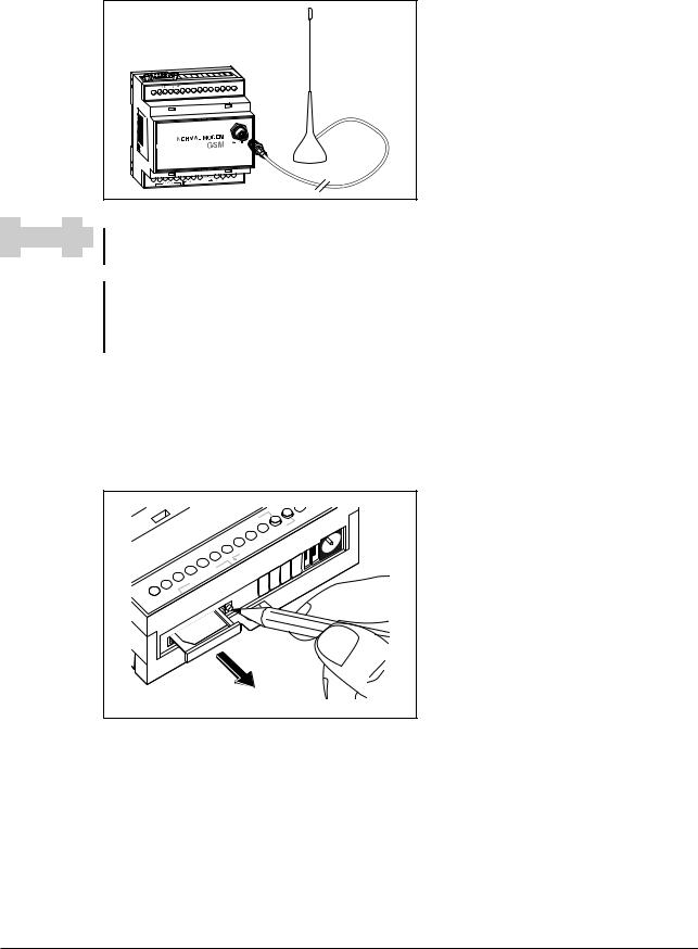
3.1.3Connecting the GSM antenna
First of all find a suitable location for mounting the GSM antenna outside of the control cabinet.
Screw the antenna plug into the antenna socket on the front of the modem.
Fig. 3-4:
When fitting the antenna plug ensure that it is seated correctly. It should be possible to turn the threaded nut easily.
|
Status GSM |
NOTES |
Standard GSM antennas with an FME plug can be used. The GSM antenna is not supplied |
|
with the modem and can be ordered separately. |
If the length of the antenna cable is not sufficient for your requirements you can use a suitable extension cable purchased as an accessory from a GSM outlet. Take into account the attenuation of these cables that will reduce the antenna gain and observe the relevant specifications of the manufacturer.
3.1.4Inserting the SIM card
The SIM card of an mobile phone provider is necessary for the use of a GSM Modem.
To insert the SIM card in the modem, open the SIM card holder on the Mitsubishi Alarm Modem by pressing the small button on the right of the holder with a pen or a pointed object.
|
- |
|
Power |
GSM |
|
Status |
||
|
||
h |
|
|
Pus |
|
|
-Card |
|
|
SIM |
|
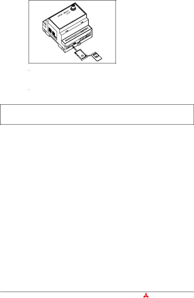
Fig. 3-3:
Push down the button until the card holder is released
You can now carefully pull out the card holder and insert your SIM card. Then push the SIM card holder back into the modem until it snaps into position.
Mitsubishi Industrial Modem |
3 - 5 |
Normal Modem GSM (MIM-G01) |
Mounting and Installation |
|
|
027954


 541034
Antenna
|
VDC |
|
|
...40 |
|
|
10 |
+ |
|
- |
|
Power |
GSM |
|
Status |
|
|
|
|
|
h |
|
|
Pus |
|
|
-Card SIM
-Card SIM
Fig. 3-5:
Insert the SIM card with the contact side facing upwards and ensure that the card is seated correctly in the recess.
Then push the SIM card holder back into the modem until it snaps into position.
NOTE |
|
If you plan to dial into your PLC via GSM, you will possibly need a SIM card and account with |
|
|
data service enabled. However, in some cases the modem may be capable of accepting |
|
|
data calls on a voice number after using the AT+CICB=0 command.For detailed information, |
|
|
contact your mobile service provider. |
E ATTENTION:
The SIM card should only be removed when the modem is in power-off state. The SIM card may become unusable if this warning is not observed.
3 - 6 |
MITSUBISHI ELECTRIC |

Mounting and Installation |
Super Modem 56k (MIM-A01) |
|
|
3.2Super Modem 56k (MIM-A01)
The MIM-A01 is a PSTN modem intended for transmission of data, SMS, e-mail and fax messages by analog telephone networks and complies to the high speed standard of V.90 and 56k. It is suitable for DIN-Rail mounting inside control boxes.
3.2.1Interfaces and Connectors
SUPER MODEM
|
|
|
|
|
|
|
Power |
Line |
|
|
|
|
|
|
|
|
|
|
|
|
|
|
||
Fig. 3-6: |
Overview of all connectors of the Super Modems 56k |
|||
Nr. |
Description |
Meaning |
|
|
|
Line |
Telephone jack RJ11 |
|
|
|
10...30VDC |
Power supply (2 screw terminals) and power supply jack |
||
|
Service |
Button |
|
|
|
LEDs |
LEDs (Power, Mail in, Line, Mail out und Modem Mode) |
||
|
RS232 Interface |
9pin D-Sub jack |
|
|
|
|
|
|
Tab. 3-4: Description of the connectors of the Modems |
|
|
|
|
|
|
NOTE |
|
|
For connecting the modem to a PC, a 1:1 serial standard cable is to be used. For information |
|
|
|
|
to connect a PLC, refer to the PLC documentation. |
Mitsubishi Industrial Modem |
3 - 7 |

Super Modem 56k (MIM-A01) |
Mounting and Installation |
|
|
3.2.2Meaning of the LEDs
The MIM-A01 got five LEDs, which display the modems operating status. After the power supply has been switched on, a self test will be executed. The end of this test is indicated by a acoustic signal (short beep).
|
|
|
|
|
SUPER MODEM |
||
|
|
|
|
|
|
|
56k |
|
|
|
DC 10...30V |
Service Mail in |
Mail out Modem Mode |
||
|
|
|
- |
+ |
Power |
Line |
COM1 (RS232) |
DC 10...30V |
Service |
Mail in |
|
Mail out |
Modem Mode |
||
- |
+ |
Power |
Line |
|
COM1 (RS232) |
||
Fig. 3-7: LEDs on the MIM-A01
LED |
Status |
Meaning |
|
Power |
Off |
No power supply, device switched off |
|
|
|
||
(yellow) |
On |
Power supply active, device switched on |
|
|
|||
|
|
|
|
Mail in |
Off |
No received message in memory |
|
|
|
||
(red) |
On |
Received message in memory |
|
|
|||
|
|
|
|
|
Off |
No telephone connection active |
|
Line |
|
|
|
Flashes |
Telephone connection becomes established |
||
(green) |
|||
|
|
||
|
On |
Telephone connection successfully established |
|
|
|
|
|
Mail out |
Off |
No outgoing messages in memory |
|
|
|
||
(yellow) |
On |
Outgoing messages in memory |
|
|
|||
|
|
|
|
Modem Mode |
Off |
Device is in Message Mode |
|
|
|
||
(red) |
On |
Device is in Modem Mode |
|
|
|||
|
|
|
Tab. 3-5: Five LEDs are used to show the state of the modem
3 - 8 |
MITSUBISHI ELECTRIC |

Mounting and Installation |
Super Modem 56k (MIM-A01) |
|
|
3.2.3Connection to the Telephone Network
Connection to telephone network (PSTN) is established via the included telephone cable and the "Line" jack of the MAM.
1 - b2
2 - W
3 - a
4 - b
6 5 4 3 2 1 5 - E
6 - a2
Fig. 3-8
The Mitsubishi Super Modem 56k supports the a/b leads (3 and 4).
To get access to your Mitsubishi Super Modem 56k, the telephone number of the connection used must be known.
3.2.4Testing the Telephone Connection
In order to check the telephone number of the connection used, plug an usual telephone into the appropriate socket and dial the number by another telephone, or from a mobile. If the telephone at the appropriate socket rings, the number is correct.
In order to check if the telephone connection supports the CLIP feature, dial from the appropriate connection to another telephone. If the calling number is shown at the called party end, the CLIP feature is supported.
If calls were successful in both directions, you can connect your Mitsubishi Super Modem. The modem is now ready to be called and receive messages.
3.2.5Telephone Exchange System
When connecting to a telephone exchange (PABX), take care if an outside line prefix is necessary.
Mitsubishi Industrial Modem |
3 - 9 |
Loading...