


 MITSUBISHI ELECTRIC
MELSEC FX2N series
Programmable Controller
Hardware Manual
FX2N
Art.No.: 66014
2001 05 07
JY992D66301-H
 MITSUBISHI ELECTRIC INDUSTRIAL AUTOMATION
FX2N Series Programmable Controllers
ENG
FRE
Foreword
•This manual contains text, diagrams and explanations which will guide the reader in the correct installation and operation of the FX2N and should be read and understood before attempting to install or use the unit.
•If in doubt at any stage during the installation of the FX2N always consult a professional electrical engineer who is qualified and trained to the local and national standards. If in doubt about the operation or use of the FX2N please consult the nearest Mitsubishi Electric distributor.
•This manual is subject to change without notice.
Préface
GER
ITL
ESP
•Le présent manuel contient des textes, des illustrations et des explications pour une installation et une utilisation correctes des API de la série FX2N. L’utilisateur doit le lire et avoir compris son contenu avant d’installer ou d’utiliser l’appareil.
•Si lors de l’installation des incertitudes persistent, n’hésitez pas à consulter un électricien compétent, qualifié et formé à l’utilisation des normes électriques locales et nationales. Contactez le représentant le plus proche de MITSUBISHI ELECTRIC si la manipulation ou l’utilisation des API de la série FX2N vous pose des problèmes.
•Le présent manuel est publié sous réserve de modifications. Ces modifications peuvent être apportées sans avis préalable.
Vorwort
•Dieses Handbuch enthält Texte, Abbildungen und Erläuterungen zur korrekten Installation und Bedienung der FX2N-SPS und sollte vor einer Installation oder einem Einsatz des Gerätes gelesen werden. Die Inhalte müssen verstanden sein.
•Wenn während der Installation etwas unklar ist, sollten Sie auf jeden Fall eine Elektrofachkraft zu Rate ziehen, die für die Anwendung der lokalen und nationalen elektrotechnischen Bestimmungen qualifiziert und ausgebildet ist. Setzen Sie sich mit dem nächst erreichbaren MITSUBISHI ELECTRIC-Händler in Verbindung, wenn bei der Bedienung oder Verwendung der FX2N-SPS etwas unklar sein sollte.
•Dieses Handbuch wird vorbehaltlich etwaiger Änderungen herausgegeben. Änderungen können ohne Hinweis vorgenommen werden.
Premessa
•Il presente manuale contiene testi, figure e spiegazioni per la corretta installazione e un corretto impiego del PC FX2N e dovrebbe essere letto e compreso prima di installare o impiegare l’apparecchio.
•Se durante l’installazione qualcosa non fosse chiaro, dovreste consultare in ogni caso uno specialista elettrico, qualificato e istruito sull’applicazione delle norme elettriche locali e nazionali. Contattate il concessionario più vicino della MITSUBISHI ELECTRIC se durante le operazioni o l’impiego del PC FX2N dovessero insorgere dei dubbi.
•Il presente manuale viene pubblicato con riserva di modifiche. Ci riserviamo il diritto di apportare modifiche al presente manuale senza alcun preavviso.
Prólogo
•Este manual contiene los textos, ilustraciones y aclaraciones para una instalación y manejo correctos de las unidades PC-FX2N (unidades de mando de memoria programable) y deberá ser leído antes de que se proceda a una instalación o a un empleo de la unidad. Es imprescindible que se entienda su contenido.
•En caso de que se presente alguna duda durante la instalación, se deberá consultar en todo caso a un electricista capacitado, que disponga de la formación correspondiente que le permita el empleo de las disposiciones electrotécnicas locales y nacionales. Póngase en contacto con el concesionario más próximo de la casa MITSUBISHI ELECTRIC, cuando se presente algún problema durante el manejo o empleo de la unidad PC-FX2N.
•Nos reservamos el derecho de efectuar en cualquier momento y sin previo aviso modificaciones o cambios en este manual.

FX2N Series Programmable Controllers
FX2N Series Programmable
Controllers
Hardware Manual
Manuel du matériel
Hardware-Handbuch
Manuale hardware
Manual de Hardware
Manual number : JY992D66301
Manual revision : H
Date |
: April 2001 |
i
FX2N Series Programmable Controllers
Guidelines for the safety of the user and protection of the FX2N
ENG This manual provides information for the installation and use of the FX2N. The manual has been written to be used by trained and competent personnel. The definition of such a person or persons is as follows;
a)Any engineer who is responsible for the planning, design and construction of automatic equipment using the product associated with this manual should be of a competent nature, (trained and qualified to the local and national standards required to fulfill that role). These engineers should be fully aware of all aspects of safety with regards to automated equipment.
b)Any commissioning or service engineer must be of a competent nature, trained and qualified to the local and national standards required to fulfill that job. These engineers should also be trained in the use and maintenance of the completed product. This includes being completely familiar with all associated documentation for the said product. All maintenance should be carried out in accordance with established safety practices.
c)All operators of the completed product should be trained to use that product in a safe and co-ordinated manner in compliance to established safety practices. The operators should also be familiar with all documentation which is connected with the actual operation of the completed equipmen.
Note : The term ‘completed equipment’ refers to a third party constructed device which contains or uses the product associated with this manual.
Notes on the symbols used in this manual
At various times through out this manual certain symbols will be used to highlight points of information which are intended to ensure the user’s personal safety and protect the integrity of the equipment. Whenever any of the following symbols are encountered, its associated note must be read and understood. Each of the symbols used will now be listed with a brief description of its meaning.
Hardware Warnings
1) Indicates that the identified danger WILL cause physical and property damage.
2)Indicates that the identified danger could POSSIBLY cause physical and property damage.
3)Indicates a point of further interest or further explanation.
Software Warnings
4) Indicates special care must be taken when using this element of software.
5) Indicates a special point of which the user of the associate software element should be aware.
6) Indicates a point of interest or further explanation.
ii

FX2N Series Programmable Controllers
Directives de sécurité pour l’utilisateur et mesures de protection pour les API de
la série FX2N.
FRE Le présent manuel contient des informations concernant l’installation et l’utilisation des API de la série FX2N. Ce manuel a été établi à l’intention d’un personnel formé et compétent. La notion de qualification est basée sur la définition suivante:
a)Tout technicien qui étudie, conçoit et construit des installations d’automatisation incorporant le présent produit, devrait posséder des connaissances suffisantes à son sujet. Sa formation et sa qualification devraient également englober les normes locales et les normes nationales. Le technicien devrait posséder des connaissances complètes sur tous les aspects liés à la sécurité dans le domaine de l’automatisation.
b)Tout spécialiste de la mise en service ou technicien du service après-vente doit posséder des connaissances de la règlementation locale et nationale en vigueur pour exécuter sûrement les opérations à effectuer lors de ces interventions. Le technicien devrait avoir reçu une formation à l’utilisation et à l’entretien des unités en incluant la famille de produits complète avec toutes les documentations afférentes. Toutes les unités d’entretien doivent toujours être conformes aux directives de sécurité courantes.
c)Tout utilisateur de l’appareil doit avoir reçu une formation à l’utilisation sûre de celui-ci, compte tenu des consignes de sécurité courantes. L’opérateur doit également se familiariser avec les documentations des autres composants de l’installation.
Important: L’expression “autres composants de l’installation” signifie tous les autres appareils de l’installation d’automatisation en liaison avec le présent produit et les informations relatives à celui-ci contenues dans le présent manuel.
Signification des symboles utilisés dans le présent manuel.
Différents symboles sont utilisés dans le présent manuel pour mettre en relief certaines informations. Ces symboles servent àexpliquer aux opérateurs les différentes instructions de sécurité et celles relatives aux mesures de protection. En présence des symboles, les instructions correspondantes doivent avoir été lues et l’information fournie doit être comprise. Tous les symboles utilisés sont énumérés ci-après avec un bref descriptif.
Avertissements relatifs au matériel
1)Désigne un danger imminent susceptible d’entraîner un dommage corporel ou un dégât matériel.
2)Désigne un danger éventuel susceptible d’entraîner un dommage corporel ou un
dégât matériel.
3)Désigne un point comportant des instructions ou des explications supplémentaires.
Avertissements relatifs au logiciel
4) Désigne un avertissement spécial dont il faut impérativement tenir compte lors de la programmation.
5) Désigne une instruction spéciale dont l’utilisateur doit tenir compte en liaison avec l’emploi de l’appareil.
6)Désigne un point comportant des instructions supplémentaires ou des explications complémentaires.
iii
FX2N Series Programmable Controllers
Sicherheitsrichtlinien für den Anwender und Schutzmaßnahmen für die FX2N-
SPS
GER Dieses Handbuch enthält Informationen zur Installation und zum Einsatz der FX2N-SPS.
Das Handbuch wurde für geschultes und kompetentes Personal erstellt. Hierbei wird für die Qualifizierung folgende Definition zugrunde gelegt:
a)Jeder Techniker, der Anlagen der Automatisierungstechnik unter Einbeziehung des Produktes plant, projektiert und errichtet, sollte diesbezüglich ausreichende Kenntnisse besitzen. Hierbei sollte die Schulung und Qualifizierung auch den Bereich der lokalen und nationalen Bestimmungen umfassen. Der Techniker sollte vollständige Kenntnisse über alle Sicherheitsaspekte im Bereich der Automatisierungstechnik besitzen.
b)Jeder Inbetriebnehmer oder Service-Techniker muß zur korrekten sicheren Aus-führung der Arbeitsvorgänge, Kenntnisse im Bereich der lokalen und nationalen Bestimmungen aufweisen. Der Techniker sollte auch in der Bedienung und Wartung der Geräteeinheiten geschult sein. Hierbei ist die gesamte Produktfamilie mit allen zugehörigen Dokumentationen gemeint. Alle Wartungseinheiten sollten stets in Übereinstimmung mit den gängigen Sicherheitsaspekten erfolgen.
c)Jeder, der das Produkt bedient, sollte in der sicheren Bedienung des Gerätes geschult sein. Die gängigen Sicherheitsaspekte sollten immer mit einbezogen werden. Der Bediener sollte sich auch mit den Dokumentationen der übrigen Anlagenausrüstung vertraut machen.
Hinweis: Mit dem Begriff ,übrige Anlagenausrüstung" sind alle weiteren Geräte der Automatisierungsanlage gemeint, die in Verbindung mit dem Produkt und den zugehörigen Handbuchinformationen stehen.
Hinweise zur der im Handbuch verwendeten Symbolik
In diesem Handbuch werden zur Hervorhebung von bestimmten Informationen verschiedene Symbole verwendet. Hiermit erhält das Bedienpersonal alle notwendigen Hinweise zu den Sicherheitsund Schutzmaßnahmen. Bei jedem Auftreten der Symbole muß der zugehörige Hinweis gelesen werden und die gegebene Information verstanden sein. Nachfolgend sind alle Symbole mit einer kurzen Beschreibung der Bedeutung aufgeführt.
Hardware-Warnhinweise
1)Bezeichnet eine unmittelbar drohende Gefahr, die zu einem Personenoder Sachschaden führen kann.
2)Bezeichnet eine möglicherweise auftretende Gefahr, die zu einem Personenoder Sachschaden führen kann.
3)Bezeichnet einen Punkt mit Hinweisen oder zusätzlichen Erläuterungen.
Software-Warnhinweise
4) Bezeichnet einen ausdrücklichen Warnhinweis, der bei der Programmierung auf jeden Fall beachtet werden muß.
5) Bezeichnet einen speziellen Hinweis, der in Verbindung mit der Bedienung vom Anwender beachtet werden sollte.
6) Bezeichnet einen Punkt mit weiteren Hinweisen oder zusätzlichen Erläuterungen.
iv
FX2N Series Programmable Controllers
Direttive di sicurezza per l’utente e misure di sicurezza per il PLC FX2N
ITL Il presente manuale contiene informazioni per l’installazione e l’impiego del PLC FX2N. Il manuale è destinato a personale addestrato e competente.
Per la qualifica del personale viene considerata la seguente definizione:
a)Ogni tecnico responsabile della pianificazione, progettazione e costruzione di impianti di automazione che impiega il prodotto descritto nel presente manuale dovrebbe avere conoscenze adeguate in merito. L’addestramento e la qualifica-zione dovrebbe includere anche il settore delle normative locali e nazionali. Il tecnico dovrebbe possedere conoscenze complete sugli aspetti della sicurezza nel settore dell’automazione.
b)Ogni tecnico addetto alla messa in funzione o all’assistenza deve dimostrare conoscenze nell’ambito delle normative locali e nazionali per garantire la sicura esecuzione delle fasi operative. Il tecnico dovrebbe essere istruito anche nell’impiego e nella manutenzione delle singole unità del prodotto. Ciò riguarda l’intera famiglia di prodotto con tutta la relativa documentazione. Tutti i lavori di manutenzione dovrebbero essere eseguiti in conformità alle direttive di sicurezza in vigore.
c)Tutti gli operatori che usano il prodotto dovrebbero essere addestrati nell’impiego sicuro dell’apparecchio nel rispetto delle normative di sicurezza in vigore. L’operatore dovrebbe familiarizzarsi anche con la documentazione delle altre parti dell’impianto.
Osservazione: Con il termine “altre parti dell’impianto” si intendono tutte le altre apparecchiature dell’impianto di automazione inerenti al prodotto e alle relative informazioni contenute nel manuale.
Osservazioni sui simboli impiegati nel manuale
Nel presente manuale vengono impiegati diversi simboli per evidenziare determinate informazioni. I simboli dovrebbero illustrare al personale addetto gli avvisi relativi riguardanti la sicurezza e le misure di sicurezza. Ogni volta che si riscontra un simbolo si dovrebbe leggere attentamente la relativa nota e osservare attentamente le informazioni ivi contenute. Elenchiamo di seguito tutti i simboli con una breve descriz-ione del loro significato.
Avvertimenti hardware
1) Indica un pericolo imminente che causa danni alle persone o agli oggetti.
2)Indica un pericolo che potrebbe causare danni alle persone o agli oggetti.
3)Indica un punto contenente avvertimenti o ulteriori illustrazioni.getti.
Avvertimenti software
4) Indica uno speciale avvertimento da osservare in ogni caso nella programmazione.
5) Indica un punto particolare di cui l’operatore dovrebbe tenere conto nell’impiego.
6) Indica un punto contenente ulteriori avvertimenti o spiegazioni supplementari.
v

FX2N Series Programmable Controllers
Instrucciones de seguridad para el usuario y medidas de protección para la unidad
PLC-FX2N
ESP Este manual comprende las informaciones correspondientes para la instalación y el uso de la unidad PLC-FX2N. El manual ha sido elaborado para un empleo por personal competente y capacitado. Al respecto, se establece la siguiente definición en cuanto a la calificación de los operadores:
a)Todo técnico, encargado de la planificación, proyección y construcción de instala-cio- nes de la técnica de automatización en función del producto deberá disponer de conocimientos satisfactorios sobre el tema. Además, la formación y calificación deberá abarcar también el campo de las disposiciones competentes locales y nacionales. El técnico deberá disponer también de plenos conocimientos sobre todos los aspectos relacionados con la seguridad en el sector de técnica de automatización.
b)Todo técnico encargado de la puesta en servicio o del servicio postventa tiene que conocer las disposiciones locales y nacionales relacionadas con la ejecución correcta y segura de las operaciones. El técnico también tiene que haber sido formado en el manejo y mantenimiento de las unidades de producción. Esto encuentra aplicación para toda la familia de productos con todas las respectivas documentaciones. Todas las unidades de mantenimiento se deberán realizar siempre de acuerdo con los aspectos de seguridad corrientes.
c)Todo operario de la unidad deberá disponer de la formación correspondiente que permita un manejo seguro de la unidad. Asimismo se deberán observar en todo momento los aspectos de seguridad corrientes. El operario se deberá familiarizar también con el contenido de la documentación de las otras unidades de la instalación.
Nota: Bajo la expresión “Las otras unidades de la instalación” se entienden todas las demás unidades de la instalación de automatización, que están relacionadas con el roducto y con las respectivas informaciones en el manual.
Observaciones sobre los símbolos empleados en este manual
En este manual se emplean diversos símbolos que permiten resaltar informaciones determinadas. Conello, se le ofrece alos operarios las indicaciones correspondientes sobre las medidas de seguridad y de protección. Cada vez que se presente un símbolo, se tiene que leer la indicación pertinente, teniéndose que entender la información obtenida. A continuación se expone una relación de todos los símbolos con una breve descripción de su significado.
Indicaciones de aviso del Hardware
1)Indica un peligro inminente, que puede conducir a daños personales o materiales.
2)Indica la posibilidad de un peligro, que puede conducir a daños personales o
materiales.
3) Indica un punto con indicaciones o aclaraciones adicionales.
Indicaciones de aviso del Software
4) Señala una indicación explícita de advertencia, que tiene que ser observada en todo caso durante la programación.
5) Señala una indicación especial, que deberá ser observada por el usuario junto con el servicio de la unidad.
6) Señala un punto con indicaciones o aclaraciones adicionales.
vi

FX2N Series Programmable Controllers
ENG
FRE
GER
ITL
ESP
The following variations of the FX2N PLC conform to the identified standards;
Les types d’API de la série FX2N suivants sont conformes aux normes et critères d’homologation mentionnés.
Die folgenden Typen der FX2N-SPS stimmen mit den aufgeführten Normen und Zulassungskriterien überein.
I seguenti tipi di PLC FX2N sono conformi alle normative e ai criteri di omologazione riportati.
La ejecución de las unidades PLC-FX2N indicadas a continuación ha sido realizada conforme a las normas y criterios de homologación indicados a continuación.
American Bureau of Shipping (ABS) Certificate number 99-KO90003-X-A
FX2N-16 |
Þ128 MR-ES/UL, MR-DS, MT-ESS/UL, MT-DSS, MR-UA1/UL |
|||
FX2N-16 |
Þ48 EX-ES/UL, EYR-ES/UL, EYT-ESS/UL, ER-ES/UL, ET-ESS/UL, |
|||
|
|
ER-UA1/UL, ER-DS, ET-DSS |
|
|
FX2N-4AD |
FX2N-4DA |
FX2N-4AD-TC |
FX2N-4AD-PT |
|
FX2N-232-IF |
FX2N-1HC |
FX2N-1PG-E |
FX2N-8AV-BD |
|
FX2N-232-BD |
FX2N-422-BD |
FX2N-485-BD |
FX2N-CNV-IF |
|
FX2N-2DA |
FX2N-2AD |
FX2N-1RM-SET |
|
|
Det Norske Veritas (DNV) Certificate number A-7412
Type approval for the ‘MELSEC - FX2N Series’
Germanischer Lloyd - Bescheinigung über Baumusterprüfung
Type test certificate (GL) Certificate number 13 827-99 HH
FX2N-16 Þ128 MR-ES/UL, MT-ESS/UL
FX2N-16 Þ 48 EX-ES/UL, EYR-ES/UL, EYT-ESS/UL, ER-ES/UL, ET-ESS/UL
FX2N-4AD |
FX2N-4DA |
FX2N-4AD-TC |
FX2N-4AD-PT |
|
FX2N-232-IF |
FX2N-1HC |
FX2N-1PG-E |
|
|
Lloyds Register (Lloyds) Type approval certificate 98/10011 |
||||
FX2N-16 |
Þ128 |
MR-ES/UL, MT-ESS/UL |
|
|
FX2N-16 |
Þ 48 EX-ES/UL, EYR-ES/UL, EYT-ESS/UL, ER-ES/UL, ET-ESS/UL |
|||
FX2N-4AD |
FX2N-4DA |
FX2N-4AD-TC |
FX2N-4AD-PT |
|
FX2N-232-IF |
FX2N-1HC |
FX2N-1PG-E |
|
|
Registro Italiano Navale (RINA) Certificate number N° ELE/129298/1 |
||||
FX2N-16 |
Þ 128 MR-ES/UL, MT-ESS/UL |
|
||
FX2N-16 |
Þ 48 EX-ES/UL, EYR-ES/UL, EYT-ESS/UL, ER-ES/UL, ET-ESS/UL |
|||
FX2N-4AD |
FX2N-4DA |
FX2N-4AD-TC |
FX2N-4AD-PT |
|
FX2N-232-IF |
FX2N-1HC |
FX2N-1PG-E |
|
|
UL, C-UL registration number E95239
FX2N- ¶¶MR-¶¶/UL FX2N- ¶¶ER-¶¶/UL FX2N- ¶¶EYR-¶¶/UL FX2N- ¶¶EX-¶¶/UL
FX2N- ¶¶MT-¶¶¶/UL FX2N- ¶¶ET-¶¶¶/UL FX2N- ¶¶EYT-¶¶¶/UL
vii
FX2N Series Programmable Controllers
viii
FX2N Series Programmable Controllers |
Introduction 1 |
1 |
ENG |
FRE |
GER |
ITL |
ESP |
Introduction |
Introduction |
Einleitung |
Introduzione |
Introducción |
2
3
4
5
6
7
8
Terminal |
Occupation |
Klemmen- |
Assegnazione |
Ocupaciones |
|
Layouts |
des bornes |
belegungen |
dei morsetti |
de bornas |
|
|
|
|
|
|
|
|
|
|
|
|
|
Installation |
Installation |
Installation |
Installazione |
Instalación |
|
Notes |
|||||
|
|
|
|
||
|
|
|
|
|
|
|
|
|
|
|
|
Power supply |
Alimentation |
Spannungs- |
Alimentazione |
Alimentación |
|
en tension |
versorgung |
della tensione |
de tensión |
||
|
|||||
|
|
|
|
|
|
|
|
|
|
|
|
Inputs |
Entrées |
Eingänge |
Ingressi |
Entradas |
|
|
|
|
|
|
|
|
|
|
|
|
|
Outputs |
Sorties |
Ausgänge |
Uscite |
Salidas |
|
|
|
|
|
|
|
|
|
|
|
|
|
Diagnostics |
Diagnostic |
Fehlerdiagnose |
Diagnostica |
Diagnóstico de |
|
d’erreurs |
fallos y errores |
||||
|
|
|
|||
|
|
|
|
|
|
|
|
|
|
|
|
Index |
Index |
Stichwort- |
Indice |
Indice |
|
verzeichnis |
analitico |
alfabético |
|||
|
|
||||
|
|
|
|
|
1-1

FX2N Series Programmable Controllers |
Introduction 1 |
1-2

FX2N Series Programmable Controllers |
Introduction 1 |
1.Introduction
ENG This manual covers the hardware installation instructions for the following programmable logic controller (PLC) product ranges;
-FX2N base and extension units
-FX2N extension and special function blocks
FRE
GER
ITL
ESP
Introduction
Le présent manuel comprend la description de l’installation pour les automates programmables (API) suivants:
-Appareils de base et appareils d’extension FX2N
-Modules d’extension et modules spéciaux FX2N
Einleitung
Dieses Handbuch umfaßt die Beschreibung der Installation für die folgenden speicherprogrammierbaren Steuerungen (SPS):
-FX2N-Grund-und Erweiterungs-geräte
-FX2N-Erweiterungs- und Sondermodule
Introduzione
Il presente manuale contiene la descrizione dell’installazione per i seguenti controllori programmabili (PLC):
-Unità FX2N base e di ampliamento
-Moduli FX2N di ampliamento e moduli speciali
Introducción
Este manual comprende la descripción de la instalación para las siguientes unidades de mando de memoria programable (PLC):
-Unidades base y de ampliación FX2N
-Módulos de ampliación y especiales FX2N
1-3

FX2N Series Programmable Controllers |
Introduction 1 |
Table 1.1: |
ENG - AC base unit |
FRE |
- |
Appareils de base |
|
|
|
|
|
|
|||||||
|
|
GER - AC-Grundgerate |
ITL |
- |
Apparecchi base AC |
|
|
|
|
|
|
||||||
|
|
ESP - Unidades base CA |
|
|
|
|
|
|
|
|
|
|
|||||
|
|
|
|
|
|
|
|
|
|
|
|
|
|
|
|
|
|
|
|
INPUTS |
|
OUTPUT TYPE |
|
|
DIMENSIONS |
|
MASS |
|
|||||||
|
|
|
|
POWER |
|
(WEIGHT) |
|
||||||||||
MODEL |
|
|
|
|
|
|
|
|
|
|
|
|
|
||||
|
|
|
|
|
|
|
|
|
|
|
|
|
|
|
|||
|
|
|
|
|
|
|
|
SUPPLY |
|
|
|
|
|
|
|
||
QTY |
|
TYPE |
QTY |
|
RELAY |
TRAN- |
|
mm (inch) |
|
kg (lbs) |
|
||||||
|
|
|
|
|
|
|
|||||||||||
|
|
|
|
|
|
|
|
||||||||||
|
|
|
|
SISTOR |
|
|
|
||||||||||
|
|
|
|
|
|
|
|
|
|
|
|
|
|
|
|
||
|
|
|
|
|
|
|
|
|
|
|
|
|
|
|
|
|
|
FX2N-16 |
8 |
|
|
8 |
|
|
|
|
|
130 (5.12) |
|
|
|
0.60 (1.3) |
|
|
|
|
|
|
|
|
|
|
|
|
|
|
|
|
|
|
|
|
|
FX2N-32 |
16 |
|
|
16 |
|
|
|
|
|
150 (5.9) |
|
|
|
0.65 (1.4) |
|
|
|
|
|
|
24V DC |
|
|
|
MT- |
|
|
|
|
|
|
|
|
|
|
FX2N-48 |
24 |
|
24 |
|
MR- |
|
|
182 (7.2) |
|
|
|
0.85 (1.9) |
|
|
|||
|
|
|
|
Sink/ |
|
|
ESS/UL |
|
|
|
|
|
|
|
|
||
|
|
|
|
|
|
ES/UL |
|
|
|
|
|
|
|
|
|||
FX2N-64 |
32 |
|
32 |
|
|
220 (8.7) |
|
|
|
1.0 (2.2) |
|
|
|||||
|
Source |
|
(Source) |
|
|
|
|
|
|
||||||||
|
|
|
|
|
|
|
|
|
|||||||||
|
|
|
|
|
|
|
|
|
|
|
|
|
|
|
|
|
|
FX2N-80 |
40 |
|
|
40 |
|
|
|
|
|
285 (11.2) |
|
|
|
1.2 (2.6) |
|
|
|
|
|
|
|
|
|
|
|
|
|
|
|
|
|
|
|
|
|
FX2N-128 |
64 |
|
|
64 |
|
|
|
|
|
350 (13.8) |
|
|
|
1.8 (4.0) |
|
|
|
|
|
|
|
|
|
|
|
|
|
|
|
|
|
|
|
|
|
FX2N-16 |
8 |
|
|
8 |
|
|
MT- |
|
100-240V |
130 (5.12) |
|
|
|
0.60 (1.3) |
|
|
|
|
|
|
|
|
|
|
|
|
|
|
|
|
|
|
|
||
|
|
|
|
|
|
|
|
|
AC +10% |
|
90 |
|
|
|
|
|
|
FX2N-32 |
16 |
|
|
16 |
|
|
E/UL |
|
150 (5.9) |
|
87 |
0.65 (1.4) |
|
|
|||
|
|
|
|
|
-15%, 50/ |
(3.5) |
|
|
|
||||||||
|
|
|
|
24V DC |
|
|
|
(Sink) |
|
|
|
(3.4) |
|
|
|
||
FX2N-48 |
24 |
|
24 |
|
|
|
182 (7.2) |
|
0.85 (1.9) |
|
|
||||||
|
|
|
|
60Hz |
|
|
|
|
|||||||||
|
Sink |
|
|
|
|
|
|
|
|
|
|||||||
|
|
|
|
|
|
|
|
|
|
|
|
|
|
|
|
|
|
FX2N-32 |
16 |
|
16 |
|
|
MS- |
|
|
150 (5.9) |
|
|
|
0.65 (1.4) |
|
|
||
|
|
|
|
|
|
|
|
|
|
|
|||||||
|
|
|
|
|
|
|
|
E/UL |
|
|
|
|
|
|
|
|
|
|
|
|
|
|
|
|
|
|
|
|
|
|
|
|
|
|
|
FX2N-48 |
24 |
|
|
24 |
|
|
(Triac |
|
|
182 (7.2) |
|
|
|
0.85 (1.9) |
|
|
|
|
|
|
|
output) |
|
|
|
|
|
|
|
||||||
|
|
|
|
|
|
|
|
|
|
|
|
|
|
|
|
|
|
|
|
|
|
|
|
|
|
|
|
|
|
|
|
|
|
|
|
FX2N-16 |
8 |
|
|
8 |
|
|
|
|
|
130 (5.12) |
|
|
|
0.60 (1.3) |
|
|
|
|
|
|
|
|
|
MR- |
|
|
|
|
|
|
|
|
|
|
|
FX2N-32 |
16 |
110V AC |
16 |
|
|
|
|
182 (7.2) |
|
|
|
0.85 (1.9) |
|
|
|||
|
|
|
|
|
UA1/ |
|
|
|
|
|
|
|
|
|
|
||
FX2N-48 |
24 |
24 |
|
|
|
|
220 (8.7) |
|
|
|
1.0 (2.2) |
|
|
||||
|
|
|
UL |
|
|
|
|
|
|
|
|
||||||
|
|
|
|
|
|
|
|
|
|
|
|
|
|
|
|
|
|
FX2N-64 |
32 |
|
|
32 |
|
|
|
|
|
285 (11.2) |
|
|
|
1.2 (2.6) |
|
|
|
|
|
|
|
|
|
|
|
|
|
|
|
|
|
||||
Table 1.2: |
ENG - DC Base Units |
FRE - Appareils de base en CC |
|
|
|
|
|
|
|||||||||
|
|
GER - DC-Grundgeräte |
ITL - Apparecchi base DC |
|
|
|
|
|
|
||||||||
|
|
ESP - Unidades CCDC |
|
|
|
|
|
|
|
|
|
|
|||||
|
|
|
|
|
|
|
|
|
|
|
|
|
|
|
|
|
|
|
|
INPUTS |
|
OUTPUT TYPE |
|
|
DIMENSIONS |
|
MASS |
|
|
||||||
|
|
|
|
POWER |
|
(WEIGHT) |
|
|
|||||||||
MODEL |
|
|
|
|
|
|
|
|
|
|
|
|
|
||||
|
|
|
|
|
|
|
|
|
|
|
|
|
|
|
|||
|
|
|
|
|
|
|
|
SUPPLY |
|
|
|
|
|
|
|
||
QTY |
|
TYPE |
QTY |
|
RELAY |
TRAN- |
|
mm (inch) |
|
kg (lbs) |
|
|
|||||
|
|
|
|
|
|
|
|
||||||||||
|
|
|
|
|
|
|
|
|
|||||||||
|
|
|
|
SISTOR |
|
|
|
||||||||||
|
|
|
|
|
|
|
|
|
|
|
|
|
|
|
|
||
|
|
|
|
|
|
|
|
|
|
|
|
|
|
|
|
|
|
FX2N-16 |
8 |
|
|
8 |
|
|
|
|
|
130 (5.1) |
|
|
|
0.60 (1.3) |
|
|
|
|
|
|
|
|
|
|
|
|
|
|
|
|
|
|
|
|
|
FX2N-32 |
16 |
|
24V DC |
16 |
|
|
|
|
24V DC |
150 (5.9) |
|
|
|
0.65 (1.4) |
|
|
|
|
|
|
|
|
|
|
MT-DSS |
|
90 |
|
87 |
|
|
|
|||
FX2N-48 |
24 |
|
Sink/ |
24 |
|
MR-DS |
+20%, |
182 (7.2) |
|
0.85 (1.9) |
|
|
|||||
|
|
(Source) |
(3.5) |
|
(3.4) |
|
|
||||||||||
|
|
|
|
Source |
|
|
|
-30% |
|
|
|
|
|
||||
FX2N-64 |
32 |
|
32 |
|
|
|
|
220 (8.7) |
|
|
|
1.0 (2.2) |
|
|
|||
|
|
|
|
|
|
|
|
|
|
|
|
||||||
|
|
|
|
|
|
|
|
|
|
|
|
|
|
|
|
|
|
FX2N-80 |
40 |
|
|
40 |
|
|
|
|
|
285 (11.2) |
|
|
|
1.2 (2.6) |
|
|
|
|
|
|
|
|
|
|
|
|
|
|
|
|
|
|
|
|
|
|
|
|
|
|
|
|
|
|
|
|
|
|
|
|
|
|
|
|
|
|
|
|
|
|
|
|
|
|
|
|
|
|
1-4 |
|
|
|
|
|
|
|
|
|
|
|
|
|
|
|
|
|
|||
|
|
|
|
|
|
|
|
|
|
|
|
|
|
|
|
|
|

FX2N Series Programmable Controllers |
Introduction 1 |
Table 1.3: |
ENG - Powered extension units |
|
|
|
|
|
||||||
|
FRE |
- Appareils d’extension alimentés en tension |
|
|
|
|
||||||
|
GER - Spannungsversorgte Erweiterungsgeräte |
|
|
|
|
|||||||
|
ITL |
|
- Apparecchi di ampliamento con alimentazione di tensione |
|
|
|||||||
|
ESP |
- Unidades de ampliación con alimentación de tensión |
|
|
||||||||
|
|
|
|
|
|
|
|
|
|
|
|
|
|
INPUTS |
|
OUTPUT TYPE |
POWER |
DIMENSIONS |
MASS |
||||||
MODEL |
|
(WEIGHT) |
||||||||||
|
|
|
|
|
|
|
SUPPLY |
|
|
|
||
|
|
|
|
|
|
|
|
|
|
|
|
|
|
QTY |
|
|
TYPE |
QTY |
RELAY |
TRANSISTOR |
mm (inch) |
|
kg (lbs) |
||
|
|
|
|
|
||||||||
|
|
|
|
|
|
|
|
|
|
|
|
|
FX2N-32 |
16 |
|
24V DC |
16 |
ER- |
ET-ESS/UL |
|
150 (5.9) |
|
|
0.65 (1.4) |
|
|
|
|
|
Sink/ |
|
100-240V |
|
|
|
|
||
FX2N-48 |
24 |
|
|
24 |
ES/UL |
(Source) |
182 (7.2) |
|
|
0.85 (1.9) |
||
|
Source |
AC +10%, |
90 |
87 |
||||||||
|
|
|
|
|
|
|
|
|||||
|
|
|
|
|
|
|
|
-15%, |
|
(3.5) |
(3.4) |
|
|
|
|
|
|
|
ER- |
|
|
|
|||
FX2N-48 |
24 |
|
110V AC |
24 |
UA1/ |
|
50/60Hz |
220 (8.7) |
|
|
1.00 (2.2) |
|
|
|
|
|
|
|
UL |
|
|
|
|
|
|
|
|
|
|
|
|
|
|
|
|
|
|
|
|
|
|
24V DC |
|
|
ET-DSS |
24V DC |
|
90 |
87 |
|
|
FX2N-48 |
24 |
|
|
Sink/ |
24 |
ER-DS |
+20% |
182 (7.2) |
0.85 (1.9) |
|||
|
|
(Source) |
(3.5) |
(3.4) |
||||||||
|
|
|
Source |
|
|
-30% |
|
|
||||
|
|
|
|
|
|
|
|
|
|
|||
|
|
|
|
|
|
|
|
|
|
|
|
|
Table 1.4: |
ENG - Extension blocks |
|
|
|
|
|
|
|
|
||||
|
FRE |
- Modules d’extension |
|
|
|
|
|
|
|
||||
|
GER - Erweiterungsmodule |
|
|
|
|
|
|
|
|||||
|
ITL |
- Moduli di ampliamento |
|
|
|
|
|
|
|
||||
|
ESP |
- Módulos de ampliación |
|
|
|
|
|
|
|
||||
|
|
|
|
|
|
|
|
|
|
|
|
|
|
|
|
|
|
INPUTS |
|
OUTPUTS |
|
DIMENSIONS |
MASS |
||||
MODEL |
|
|
|
|
(WEIGHT) |
||||||||
|
|
|
|
|
|
|
|
|
|
|
|||
|
|
|
|
|
|
|
|
|
|
|
|
|
|
|
|
|
QTY |
|
TYPE |
QTY |
DEVICE |
|
TYPE |
mm (inch) |
|
kg (lbs) |
|
|
|
|
|
|
|
|
|
|
|
|
|
|
|
FX0N-8EX-UA1/UL |
|
|
|
110V AC |
|
|
|
|
|
|
|
|
|
|
8 |
|
inputs |
|
|
|
|
|
|
|
|
||
|
|
|
|
|
|
|
|
|
|
|
|
||
|
|
|
|
|
|
|
|
|
|
|
|
|
|
FX0N-8EX-ES/UL |
|
|
|
Sink/Source |
|
|
|
|
43 (1.7) |
|
|
0.2 (0.44) |
|
FX0N-8ER-ES/UL |
|
4 |
|
24V DC |
4 |
Relay |
|
|
|
|
|||
|
|
|
|
|
|
|
|
||||||
|
|
|
|
|
|
|
|
|
|
|
|
|
|
FX0N-8EYR-ES/UL |
|
|
|
|
8 |
|
|
|
90 |
87 |
|
||
|
|
|
|
|
|
|
|
|
|||||
FX0N-8EYT-ESS/UL |
|
|
|
|
8 |
Transistor |
|
Source |
|
(3.5) |
(3.4) |
|
|
|
|
|
|
|
|
|
|
|
|
|
|
|
|
FX0N-16EX-ES/UL |
|
16 |
|
Sink/Source |
|
|
|
|
|
|
|
|
|
|
|
24V DC |
|
|
|
|
|
|
|
|
|||
|
|
|
|
|
|
|
|
|
70 (2.8) |
|
|
0.3 (0.66) |
|
|
|
|
|
|
|
|
|
|
|
|
|
||
FX0N-16EYR-ES/UL |
|
|
|
|
16 |
Relay |
|
|
|||||
|
|
|
|
|
|
|
|
|
|
||||
|
|
|
|
|
|
|
|
|
|
|
|
||
FX0N-16EYT-ESS/UL |
|
|
|
16 |
Transistor |
|
Source |
|
|
|
|
||
|
|
|
|
|
|
|
|
|
|
|
|
|
|
FX2N-16EX-ES/UL |
|
16 |
|
Sink/Source |
|
|
|
|
|
|
|
|
|
|
|
24V DC |
|
|
|
|
|
90 |
87 |
|
|||
|
|
|
|
|
|
|
|
|
40 (1.6) |
0.3 (0.66) |
|||
|
|
|
|
|
|
|
|
|
|
||||
FX2N-16EYR-ES/UL |
|
|
|
|
16 |
Relay |
|
|
(3.5) |
(3.4) |
|||
|
|
|
|
|
|
|
|
||||||
|
|
|
|
|
|
|
|
|
|
|
|
||
FX2N-16EYT-ESS/UL |
|
|
|
16 |
Transistor |
|
Source |
|
|
|
|
||
|
|
|
|
|
|
|
|
|
|
|
|
|
|
1-5
FX2N Series Programmable Controllers Introduction 1
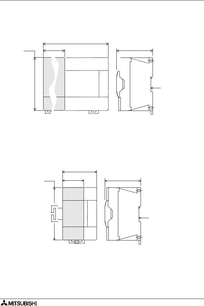
Figure 1.1: |
|
|
|
|
|
|
|
|
|
ENG |
- Dimensioned unit |
FRE |
- Dimensions |
||||
|
GER |
- Abmessungen |
ITL |
- Dimensioni |
||||
|
ESP |
- Dimensiones |
|
|
|
|
||
|
|
|
|
350 |
|
|
|
|
90 |
130 |
(13.78) |
|
|
|
87 (3.42) |
||
|
|
|
|
|||||
(3.54) |
(5.11) |
|
|
|
|
|
||
|
|
|
|
|
|
|
|
|
|
|
|
|
|
|
|
|
|
|
|
|
|
|
|
|
|
|
DIN rail : 35mm
(1.38)
UNITS: mm (inches)
Figure 1.2:
ENG |
- Extension block dimensions |
|
FRE |
- Dimensions des modules d’extension |
|
GER |
- Abmessungen der Erweiterungsmodule |
|
ITL |
- Dimensioni dei moduli di ampliamento |
|
ESP |
- Dimensiones de los módulos de ampliación |
|
|
70 |
|
90 |
(2.76) |
87 (3.42) |
40 |
||
(3.54) (1.57)
DIN rail : 35mm
(1.38)
UNITS: mm (inches)
1-6

FX2N Series Programmable Controllers |
Introduction 1 |
Table 1.5: |
ENG - Special function blocks |
|
FRE |
- Modules spéciaux |
GER - |
Sondermodule |
||||||||||
|
ITL - Moduli speciali |
|
|
|
ESP |
- Módulos especiales blocks |
|
|
||||||||
|
|
|
|
|
|
|
|
|
|
|
|
|
|
|
||
|
|
|
NUMBER |
POWER SUPPLY |
DIMENSIONS |
MASS |
||||||||||
|
|
|
|
OF I/O |
|
(WEIGHT) |
||||||||||
MODEL |
DESCRIPTION |
|
|
|
|
|
|
|
|
|
||||||
|
|
|
|
|
|
|
|
|
|
|
|
|
|
|
||
|
|
|
|
I |
|
|
O |
Internal |
External |
|
mm |
|
kg |
|||
|
|
|
|
|
|
5V DC |
24V DC |
|
(inches) |
|
(lbs) |
|||||
|
|
|
|
|
|
|
|
|
|
|
|
|||||
|
|
|
|
|
|
|
|
|
|
|
|
|
|
|
|
|
FX2N-2AD |
Analog to digital converter |
|
|
|
|
8 |
|
|
20mA |
50mA |
43 (1.7) |
|
|
|
0.2 (0.44) |
|
|
|
|
|
|
|
|
|
|
|
|
|
|
|
|
||
FX2N-2DA |
Digital to analog converter |
|
|
|
|
8 |
|
|
30mA |
85mA |
|
|
|
|||
|
|
|
|
|
|
|
|
|
|
|
||||||
|
|
|
|
|
|
|
|
|
|
|
|
|
|
|
||
FX2N-4DA |
Digital to analog converter |
|
- |
|
8 |
|
- |
30mA |
200mA |
55 (2.1) |
|
|
|
|
||
|
|
|
|
|
|
|
|
|
|
|
|
|
|
|
|
|
FX2N-4AD |
Analog to digital converter |
|
- |
|
8 |
|
- |
30mA |
55mA |
|
|
|
|
|||
|
|
|
|
|
|
|
|
|||||||||
|
|
|
|
|
|
|
|
|
|
|
|
|
|
|
|
|
FX2N-8AD |
Analog to digital converter |
|
|
|
|
8 |
|
|
50mA |
80mA |
75 (3.0) |
|
|
|
0.3 (0.66) |
|
|
|
|
|
|
|
|
|
|
|
|
|
|
|
|
|
|
FX2N-4AD-PT |
PT100 probe interface |
|
- |
|
8 |
|
- |
30mA |
50mA |
|
90 |
|
|
|||
|
|
|
|
|
|
|
||||||||||
|
|
|
|
|
|
|
|
|
|
|
|
|
|
|
|
|
FX2N-4AD-TC |
Thermo-couple interface |
|
- |
|
8 |
|
- |
30mA |
50mA |
55 (2.1) |
(3.5) |
|
|
|
||
|
|
|
|
|
|
|
|
|
|
|
|
|
|
|
||
FX2N-1HC |
High speed counter |
|
- |
|
8 |
|
- |
90mA |
NA |
|
|
|
87 |
|
||
|
|
|
|
|
|
|
|
|
|
|
|
|
|
|
(3.4) |
|
FX2N-1PG |
Pulse output, Position control |
|
- |
|
8 |
|
- |
55mA |
40mA |
43 (1.7) |
|
|
0.2 (0.44) |
|||
|
|
|
|
|
|
|||||||||||
|
|
|
|
|
|
|
|
|
|
|
|
|
|
|
||
FX2N-232IF |
RS232 Interface block |
|
- |
|
8 |
|
- |
40mA |
80mA |
55 (2.1) |
|
|
|
0.3 (0.66) |
||
|
|
|
|
|
|
|
|
|
|
|
|
|
|
|
|
|
FX2N-32CCL |
CC-Link Slave Interface |
|
|
|
|
8 |
|
|
130mA |
50mA |
|
|
|
|
0.2 (0.44) |
|
|
|
|
|
|
|
|
|
|
|
|
|
|
|
|
|
|
FX2N-16LNK-M |
I/O Link Remote Master module |
|
|
|
NA |
|
200mA |
90mA |
43 (1.7) |
|
|
|
0.5 (1.10) |
|||
|
|
|
|
|
|
|
|
|
|
|
|
|
|
|
|
|
FX2N-64DNET |
DeviceNet Slave Module |
|
|
|
|
NA |
|
120mA |
50mA |
|
94 |
|
|
0.2 (0.44) |
||
|
|
|
|
|
|
(3.7) |
|
|
||||||||
|
|
|
|
|
|
|
|
|
|
|
|
|
|
|
|
|
|
|
|
|
|
|
|
|
|
|
|
|
|
|
|
|
|
FX2N-32ASI-M |
ASI Master Module |
|
|
|
|
8 |
|
|
150mA |
70mA |
55 (2.1) |
90 |
|
|
0.2 (0.44) |
|
|
|
|
|
|
|
|
|
|
|
|
|
|
(3.5) |
|
|
|
FX2N-32DP-IF |
Profibus-DP Interface Unit |
|
|
|
|
NA |
|
NA |
NA |
75 |
|
|
0.4 (0.88) |
|||
|
|
|
|
|
|
|
|
|
|
|
|
|
|
|
|
|
FX2N-1RM-E- |
Programmable Cam Switch |
|
|
|
|
8 |
|
|
NA |
250mA |
|
111 |
|
97 |
0.5 (1.10) |
|
SET |
|
|
|
|
|
|
55 (2.1) |
(4.37) |
|
|||||||
|
|
|
|
|
|
|
|
|
|
|
|
|
|
|||
|
|
|
|
|
|
|
|
|
|
|
|
|
|
|
|
|
FX2N-2LC |
Temperature Control Block |
|
|
|
|
8 |
|
|
70mA |
55mA |
|
|
|
|
0.3 (0.66) |
|
|
|
|
|
|
|
|
|
|
|
|
|
|
|
|
|
|
FX2N-10GM |
Positioning Controller (1 axis) |
|
|
|
|
8 |
|
|
NA |
NA |
60 |
|
|
|
0.3 (0.66) |
|
|
|
|
|
|
|
|
|
|
|
|
|
|
|
|
||
FX2N-20GM |
Positioning Controller (2 axis) |
|
|
|
|
8 |
|
|
86 |
90 |
|
87 |
0.4 (0.88) |
|||
|
|
|
|
|
|
|
|
|
||||||||
|
|
|
|
|
|
|
|
|
|
|
|
|
|
|
||
FX0N-3A |
Analog/Digital converter |
|
- |
|
8 |
|
- |
30mA |
90mA* |
|
(3.5) |
|
(3.4) |
0.2 (0.44) |
||
|
|
|
|
|
|
|
|
|
|
|
|
|
|
|
|
|
FX0N-16NT |
Net-mini interface |
|
8 |
|
|
8 |
|
20mA |
60mA |
43 (1.7) |
|
|
|
|
||
|
|
|
|
|
|
|
|
|
|
|
|
|
|
|
|
|
FX0N-32NT-DP |
Profibus DP Interface |
|
- |
|
8 |
|
- |
170mA |
20mA |
|
|
|
|
0.3 (0.66) |
||
|
|
|
|
|
|
|
|
|
|
|
|
|
|
|
|
|
|
|
|
|
|
|
|
|
|
|
|
|
* Internal 24V DC |
|
|||
1-7

FX2N Series Programmable Controllers |
|
|
|
|
|
|
|
|
|
|
Introduction 1 |
||||
|
|
|
|
|
|
|
|
|
|
* |
|
|
|
|
|
Table 1.6: |
ENG - Special function blocks FRE |
- Modules spéciaux |
GER - Sondermodule |
||||||||||||
|
|
ITL - Moduli speciali |
|
ESP |
- Módulos especiales blocks |
|
|
||||||||
|
|
|
|
NUMBER |
|
POWER SUPPLY |
|
DIMENSIONS |
MASS |
||||||
|
|
|
|
OF I/O |
|
|
(WEIGHT) |
||||||||
MODEL |
|
DESCRIPTION |
|
|
|
|
|
|
|
||||||
|
|
|
|
|
|
|
|
|
|
|
|
|
|||
|
|
|
|
I |
|
|
O |
|
Internal |
External |
|
|
mm |
|
kg |
|
|
|
|
|
|
|
5V DC |
24V DC |
|
|
(inches) |
|
(lbs) |
||
|
|
|
|
|
|
|
|
|
|
|
|
||||
|
|
|
|
|
|
|
|
|
|
|
|
|
|
|
|
FX-2DA |
|
|
Digital to analog converter |
- |
8 |
- |
|
30mA |
130mA |
|
|
|
|
0.5 (1.1) |
|
|
|
|
|
|
|
|
|
|
|
|
|
|
|
|
|
FX-4DA |
|
|
Digital to analog converter |
- |
8 |
- |
|
30mA |
200mA |
|
|
|
|
0.3 (0.66) |
|
|
|
|
|
|
|
|
|
|
|
|
|
|
|
|
|
FX-4AD |
|
|
Analog to digital converter |
- |
8 |
- |
|
30mA |
50mA |
|
73 (2.9) |
|
|
|
|
|
|
|
|
|
|
|
|
|
|
|
|
|
|
|
|
FX-2AD-PT |
|
PT100 probe interface |
- |
8 |
- |
|
30mA |
50mA |
|
140 |
95 |
0.5 (1.1) |
|||
|
|
|
|
||||||||||||
|
|
|
|
|
|
|
|
|
|
|
|
|
|||
FX-4AD-TC |
|
Thermo-couple interface |
- |
8 |
- |
|
40mA |
60mA |
|
|
|||||
|
|
|
|
(5.5) |
(3.7) |
|
|||||||||
|
|
|
|
|
|
|
|
|
|
|
|
|
|
||
FX-1HC |
|
|
High speed counter |
- |
8 |
- |
|
70mA |
- |
|
|
|
|
|
|
|
|
|
|
|
|
|
|
|
|
|
|
|
|
||
FX-1PG-E |
|
Pulse output, Position control |
- |
8 |
- |
|
60mA |
40mA |
|
45 (1.8) |
|
|
0.3 (0.66) |
||
|
|
|
|
|
|
|
|
|
|
|
|
|
|
||
FX-16NP/NT |
|
Net-mini interface |
16 |
|
|
8 |
|
80mA |
120mA |
|
|
|
|
|
|
|
|
|
|
|
|
|
|
|
|
|
|
|
|
||
FX-16NP/NT-S3 |
Net-mini-S3 interface |
8 |
8 |
8 |
|
80mA |
100mA |
|
73 (2.9) |
|
|
0.4 (0.88) |
|||
|
|
|
|
|
|
|
|
|
|
|
|
|
|
|
|
FX-1GM |
|
|
Position Control (1 axis) |
- |
8 |
- |
|
AC supply |
|
160 |
|
|
1.5 (3.3) |
||
|
|
|
|
(6.3) |
|
|
|||||||||
|
|
|
|
|
|
|
|
|
|
|
|
140 |
95 |
|
|
|
|
|
|
|
|
|
|
|
|
|
|
|
|
||
FX-10GM |
|
|
Position Control (1 axis) |
- |
8 |
- |
|
- |
210mA |
|
50 (1.9) |
|
|||
|
|
|
|
(5.5) |
(3.7) |
|
|||||||||
|
|
|
|
|
|
|
|
|
|
|
|
|
0.4 (0.88) |
||
FX-20GM |
|
|
Position Control (2 axis) |
- |
8 |
- |
|
AC supply |
|
110 |
|
|
|||
|
|
|
|
(4.3) |
|
|
|
||||||||
|
|
|
|
|
|
|
|
|
|
|
|
|
|
|
|
|
|
|
|
|
|
|
|
|
|
|
|
|
|||
ENG |
FX Special functions blocks must be connected at the right end of the system using the FX2N- |
||||||||||||||
|
CNV-IF convertion interface. |
|
|
|
|
|
|
|
|
|
|
|
|
||
FRE |
Des blocs de fonctions spéciales FX doivent être connectés à l’extrémité droite du système en |
||||||||||||||
utilisant l’interface de conversion FX2N-CNV-IF.
GER Die FX-Sondermodule müssen an der rechten Seite der Systemkonfiguration über die Schnittstelle FX2N-CNV-IF angeschlossen werden.
ITL I blocchi delle funzioni speciali FX devono essere collegati con l’estremità destra del sistema usando l’interfaccia di conversione FX2N-CNV-IF.
ESP |
El bloque funcional especial FX debe ser conectado al extremo derecho del sistema a través |
|
de la interfase de conversión FX2N-CNV-IF.
1-8
FX2N Series Programmable Controllers |
Introduction 1 |
1.1Unit Accessories
ENG Each powered extension unit comes with: 1 I/O label kit and a 55mm (2.17 inch) extension cables.
Each extension and special function block comes with an I/O label kit.
FRE
Accessoires d’un appareil
Etendue de la fourniture d’un appareil d’extension alimenté en tension: 1 jeu d’auto-collants E/ S et le câble d’extension de 55 mm de long.
Chaque module d’extension et module spécial est livré avec un jeu d’autocollants E/S.
GER
Zubehör einer Geräteeinheit
Lieferumfang eines spannungsversorgten Erweiterungsgerätes: 1 E-/A-Aufklebersatz und die beiden Erweiterungskabel mit 55 mm Länge. Jedes Erweiterungsund Sondermodul wird mit einem E-/A-Aufklebersatz ausgeliefert.
ITL
Accessori di un apparecchio
Volume di fornitura di un apparecchio di ampliamento con alimentazione di tensione: no.1 set di adesivi I/O e i due cavi di ampliamento di 55 mm di lunghezza. Ogni modulo di ampliamento e ogni modulo speciale viene fornito con un set di adesivi I/O.
ESP
Accesorios de una unidad de producción
Volumen de suministro de una unidad de ampliación con alimentación de tensión: 1 juego de etiquetas autoadhesivas E/S y los dos cables de ampliación con una longitud de 55 mm. Cada módulo de ampliación y módulo especial es suministrado con un juego de etiquetas autoadhesivas de E/S.
1.2
ENG |
World Specification |
FRE |
Version internationale |
GER |
Weltweite Ausführung. |
ITL |
Esecuzione internazionale. |
ESP |
Modelo internacional |
|
|
Table 1.7:
Version |
|
Modelo |
Weltweite |
Versione |
|
World/Japanese |
internacional |
|
internationale |
/japanische Ausf. |
internazionale |
Spec. |
/modelo para el |
|
/japonaise. |
|
/giapponese |
|
|
Japón |
ITEM |
|
ENG |
FRE |
GER |
ITL |
ESP |
|
|
|
|
|
|
|
|
|
|
|
|
|
|
|
Tous les appareils |
Alle Geräte der |
Tutti gli |
Todas las unidades |
|
|
|
ONLY WORLD |
en version |
apparecchi |
del modelo |
|
||
|
|
weltweiten Ausf. |
|
|||||
|
|
SPEC. PLC’s have |
internationale |
della versione |
internacional |
|
||
|
|
haben die |
|
|||||
Input S/S |
this terminal |
possèdent les |
internazionale |
disponen de las |
|
|||
Klemmen: |
|
|||||||
terminal |
-ve S/S |
bornes suivantes: |
hanno i morsetti: |
bornas: |
|
|||
(- S/S) Klemme = |
|
|||||||
Sink/Source |
connection = source |
Borne (- S/S)= |
morsetto (- S/S)= |
Borna (- S/S) = |
|
|||
Source, |
|
|||||||
|
|
+ve S/S |
source (émetteur), |
source, |
Source, |
|
||
|
|
(+ S/S) Klemme = |
|
|||||
|
|
connection = sink |
Borne (+ S/S)= |
morsetto (+ S/S) = |
Borna (+ S/S) = |
|
||
|
|
Sink |
|
|||||
|
|
|
|
sink (récepteur) |
sink |
Sink |
|
|
|
|
|
|
|
|
|||
|
|
|
|
|
|
|
|
|
|
|
|
|
Tous les appareils |
|
Tutti i modelli |
Todos los modelos |
|
|
|
|
|
de type japonais |
Alle japanischen |
para el Japón |
|
|
|
|
Japanese models |
giapponesi hanno il |
|
||||
|
|
sont équipés d’un |
Typen mit SINK- |
disponen de |
|
|||
|
|
are ALWAYS SINK. |
collegamento |
|
||||
Outputs |
raccord SINK. Pour |
Anschluß. Bei der |
unaconexión SINK. |
|
||||
World spec |
SINK.Nella |
|
||||||
Transistor |
la version |
weltweiten Ausf. |
En el modelo |
|
||||
models depend on |
versione |
|
||||||
|
|
internationale, cela |
vom Gerätetyp |
internacional en |
|
|||
|
|
the PLC selection |
internazionale ciò |
|
||||
|
|
dépend des types |
abhängig. |
función del tipo de |
|
|||
|
|
|
|
dipende dal modello. |
|
|||
|
|
|
|
d’appareils. |
|
unidad. |
|
|
|
|
|
|
|
|
|
|
|
|
|
This is a Japanese |
Ceci est une série |
Dies ist eine |
Questa è la serie |
Esta es una serie |
|
|
FX2 |
japanische SPS- |
|
||||||
series PLC |
d’API japonaise. |
giapponese di PLC. |
PLC japonesa. |
|
||||
|
|
Serie. |
|
|||||
|
|
|
|
|
|
|
|
|
|
|
|
|
|
|
|
|
|
|
|
|
|
|
|
|
|
|
|
|
|
|
|
|
|
1-9 |
|
|
|
|
|
|
|
|
||
|
|
|
|
|
|
|
|
|
FX2N Series Programmable Controllers Introduction 1
1.3
ENG |
Model name |
|
FRE |
Désignation des types d’appareils. |
|||||
GER |
Gerätetypenbezeichnung |
ITL |
Designazione dei modelli. |
||||||
ESP Designación del tipo de unidad |
|
|
|
|
|||||
Table 1.8: |
|
|
|
|
|
|
|||
|
|
|
Model table |
Description |
Typenbeschrei- |
Descrizione |
Descripción |
||
|
|
|
des types |
bung |
dei modelli |
del tipo |
|||
|
|
|
|
||||||
|
|
|
|
|
|
|
|||
REF |
ENG |
FRE |
GER |
ITL |
ESP |
||||
|
|
|
|
|
|
|
|
||
A) |
PLC type, FX, |
Série d’API: FX, |
SPS-Serie: FX, |
Serie di PLC: FX, |
Serie PLC: FX, |
||||
FX0N, FX2N |
FX0N, FX2N |
FX0N,FX2N |
FX0N, FX2N |
FX0N, FX2N |
|||||
|
|
|
|||||||
|
|
|
|
|
|
|
|
||
|
|
|
Total number of I/O |
Nombre d’entrées |
Anzahl der Ein-/ |
Numero di |
Número de las |
||
B) |
channels |
et de sorties |
Ausgänge |
ingressi/uscite |
entradas/salidas |
||||
FX-8AV = 8 ch. |
FX-8AV = 8 Ka. |
FX-8AV = 8 |
FX-8AV = 8 Ka. |
FX-8AV = 8 Ca. |
|||||
|
|
|
FX2N-64= 64ch. |
FX2N-64 = 64 Ka. |
FX2N-64 = 64 |
FX2N-64 = 64 Ka. |
FX2N-64 = 64 Ca. |
||
|
|
|
FX-16EX = 16ch. |
FX-16EX = 16 Ka. |
FX-16EX = 16 |
FX-16EX = 16 Ka. |
FX-16EX = 16 Ca. |
||
|
|
|
|
|
|
|
|
||
|
|
|
Unit type Types |
d’appareils |
Gerätetypen |
Modelli |
Tipos de unidad |
||
|
|
|
|
|
|
|
|
||
|
|
M |
MPU-base unit |
Appareil de base |
Grundgerät |
Apparecchio base |
Unidad base |
||
|
|
|
|
|
|
|
|
|
|
|
|
|
|
Appareils |
Spannung- |
Apparecchio di |
Unidad de |
||
|
|
|
Powered |
d’extension |
ampliamento |
ampliación con |
|||
|
|
E |
sversorgtes |
||||||
|
|
extension unit |
alimentés en |
con alimentazione |
alimentación de |
||||
C) |
|
|
Erweiterungsgerät |
||||||
|
|
|
tension |
di tensione |
tensión |
||||
|
|
|
|
|
|||||
|
|
|
|
|
|
|
|
|
|
|
|
|
Extension |
Module d’extension, |
Erweiterungsmodul, |
Modulo di |
Módulo de |
||
|
|
EX |
ampliamento, |
ampliación, |
|||||
|
|
block, input |
entrées |
Eingänge |
|||||
|
|
|
ingressi |
entradas |
|||||
|
|
|
|
|
|
|
|||
|
|
|
|
|
|
|
|
||
|
|
EY |
Extension |
Module |
Erweiterungsmodul, |
Modulo di |
Módulo de |
||
|
|
block, output |
d’extension, sorties |
Ausgänge |
ampliamento, uscite |
ampliación, salidas |
|||
|
|
|
|||||||
|
|
|
|
|
|
|
|
||
|
|
|
Output type |
Technologie de |
Ausgangs- |
Tecnologia di |
Tecnología de |
||
|
|
|
sortie |
technologie |
uscita |
salida |
|||
|
|
|
|
||||||
|
|
|
|
|
|
|
|||
D) |
|
R |
Relay |
Relais |
Relais |
Relè |
Relé |
||
|
|
S |
Triac (SSR) |
Triac (SSR) |
Triac (SSR) |
Triac (SSR) |
Triac (SSR) |
||
|
|
|
|
|
|
|
|
||
|
|
T |
Transistor |
Transistor |
Transistor |
Transistor |
Transistor |
||
|
|
|
|
|
|
|
|
|
|
|
|
|
Features |
Variantes de |
Modellvarianten |
Varianti |
Variantes de |
||
|
|
|
modèles |
modelos |
|||||
|
|
|
|
|
|
|
|||
|
|
|
|
|
|
|
|
||
|
|
omit |
AC, Japanese spec. |
CA, version |
AC, japanische |
AC, versione |
CA, modelo para el |
||
|
|
or E* |
japonaise |
Ausf. |
giapponese |
Japón |
|||
|
|
|
|
|
|
|
|
||
|
|
D |
24V DC |
24V CC, version |
DC 24V, japanische |
24V DC, versione |
24V CC, modelo |
||
|
|
Japanese spec. |
japonaise |
Ausf. |
giapponese |
para el Japón |
|||
|
|
|
|||||||
|
|
|
|
|
|
|
|
||
|
|
DS* |
24V DC |
CC, Version |
DC, weltweite |
DC, Versione |
CC, Modelo |
||
|
|
World spec. |
internationale |
Ausf. |
internazionale |
internacional |
|||
|
|
|
|||||||
|
|
|
|
|
|
|
|
||
|
|
|
24V DC |
CC, Version |
DC, weltweite |
DC, Versione |
CC, Modelo |
||
E) |
|
DSS* |
World spec., DC |
internationale, CC |
Ausf., DC Source- |
internazionale, DC |
internacional, CC |
||
|
|
source transistor |
transistor source |
Transistor |
transistor source |
transistor Source |
|||
|
|
|
|
|
|
|
|
||
|
|
|
AC Power Supply |
CA, Version |
AC, weltweite |
AC, Versione |
CA, Modelo |
||
|
|
ES |
World spec., |
internationale, |
Ausf., |
internazionale, |
internacional, |
||
|
|
|
Relay |
Relais |
Relais |
Relè |
Relé |
||
|
|
|
|
|
|
|
|
||
|
|
|
AC Power Supply |
CA, Version |
AC, weltweite |
AC, Versione |
CA, Modelo |
||
|
|
ESS |
World spec., DC |
internationale, CC |
Ausf., DC Source- |
internazionale, DC |
internacional, CC |
||
|
|
|
source transistor |
transistor source |
Transistor |
transistor source |
transistor Source |
||
|
|
|
|
|
|
|
|
||
|
|
|
|
Tension de |
AC -Service- |
Tensione di servizio |
Tensión de |
||
|
|
|
AC Power Supply, |
Spannung, |
AC, |
servicio CA, |
|||
|
|
UA1 |
service CA, Tension |
||||||
|
|
AC inputs |
AC Eingangs- |
Tensione di |
Tensión de |
||||
|
|
|
d’entreé CA |
||||||
|
|
|
|
spannung |
ingresso AC |
entrada CA |
|||
|
|
|
|
|
|||||
|
|
|
|
|
|
|
|
||
F) |
|
UL* |
CE, UL registered |
Produit agréé par |
CE, UL- |
Prodotto registrato |
Producto registrado |
||
|
product |
l’UL, CE |
registriertes Produkt |
CE, UL |
según CE, UL |
||||
|
|
|
|||||||
|
|
|
|
|
|
|
|
|
|
*Note: See Table 1.9
1-10
FX2N Series Programmable Controllers Introduction 1
Table 1.9:
Model |
CE |
UL |
|
|
|
FX2N-**MR-DS, **MT-DSS |
ü |
ü |
|
|
|
FX2N-**M*-E/UL |
û |
ü |
|
|
|
FX2N-16EYS |
û |
ü |
|
|
|
|
Figure 1.3: |
|
|
|
|
|
|
|
ENG |
- Model name |
|
|
|
|
|
|
FRE |
- Désignation des |
|
|
|
|
|
|
|
types d’appareils. |
|
||||
|
|
|
|
|
|||
|
GER |
- Typenbezeichnung |
|
|
|
||
|
ITL |
- Modello. |
|
|
|
|
|
|
ESP |
- Designación del tipo |
|
|
|||
1.4 |
|
|
|
|
|
|
|
ENG |
Serial numbers |
|
FRE |
Numéro de série |
|
||
GER |
Seriennummer |
|
ITL |
Numero di serie |
|
||
ESP |
Número de serie |
|
|
|
|
||
Table 1.10: |
|
|
|
|
|
||
|
Notes on serial |
Explication du |
Erläuterung der |
Spiegazione del |
Aclaración del |
||
|
numbers |
numéro de série |
Seriennummer |
numero di serie |
número de serie |
||
REF |
ENG |
FRE |
GER |
|
ITL |
ESP |
|
1 |
Production year |
Année de production |
Produktionsjahr |
Anno di produzione |
Año de producción |
||
2 |
Production month |
Mois de production |
Produktionsmonat |
Mese di produzione |
Mes de producción |
||
3 |
Production |
Numéro de série de |
Seriennummer der |
Numero di serie |
Número de serie de |
||
serial number |
la production |
Produktion |
della produzione |
la producción |
|||
|
|||||||
Figure 1.4:
ENG - Serial number
FRE - Numéro de série
GER - Seriennummer
ITL - Numero di serie
ESP - Número de serie
|
|
1-11
FX2N Series Programmable Controllers |
Introduction 1 |
1.5
ENG
GER
ESP
Configuration |
FRE Construction du système |
|
Systemaufbau |
ITL |
Struttura del sistema |
|
|
|
Configuración del sistema
Figure 1.5:
ENG - Schematic system
FRE - Représentation schématique de la construction du système GER - Schematischer Systemaufbau
ITL - Struttura schematica del sistema
ESP - Configuración esquemática del sistema
|
|
|
|
FX-EEPROM-4 |
|
FX-EPROM-8 |
|
|
|
|
|
|
|
|
FX-EEPROM-8 |
|
FX-RAM-8 |
|
|
|
|
|
|
|
|
FX-EEPROM-16 |
FX2N-ROM-E1 |
G |
|
|
|
|
|
|
|
|
|
|
2 |
|
|
|
|
|
|
|
FX2N-16MR-ES/UL |
FX2N-16MT-ESS/UL |
|
|
|
|||
|
|
|
FX2N-32MR-ES/UL |
FX2N-32MT-ESS/UL |
|
|
|
|||
|
|
|
|
|
|
|||||
FX2N-8AV-BD |
|
FX2N-48MR-ES/UL |
FX2N-48MT-ESS/UL |
|
|
|
||||
|
FX2N-64MR-ES/UL |
FX2N-64MT-ESS/UL |
|
|
|
|||||
FX2N-232-BD |
|
|
|
|
||||||
|
FX2N-80MR-ES/UL |
FX2N-80MT-ESS/UL |
|
|
|
|||||
FX2N-485-BD |
|
|
|
|
||||||
|
FX2N-128MR-ES/UL |
FX2N-128MT-ESS/UL |
|
|
|
|||||
FX2N-422-BD |
|
|
|
|
||||||
|
FX2N-16MR-DS |
|
FX2N-16MT-DSS |
|
|
|
||||
|
|
|
|
4 |
||||||
FX2N-CNV-BD+ |
1 FX2N-32MR-DS |
|
FX2N-32MT-DSS |
|||||||
|
FX2N-48MR-DS |
|
FX2N-48MT-DSS |
|
|
|
||||
FX0N-232ADP |
|
|
|
|
|
|||||
|
FX2N-64MR-DS |
|
FX2N-64MT-DSS |
|
|
|
||||
|
|
|
|
|
|
|
||||
FX2N-CNV-BD+ |
|
FX2N-80MR-DS |
|
FX2N-80MT-DSS |
|
|
|
|||
|
FX2N-16MR-UA1/UL |
FX2N-16MT-E/UL |
|
|
|
|||||
FX0N-485ADP |
|
|
|
|
|
|||||
|
|
FX2N-32MR-UA1/UL |
FX2N-32MT-E/UL |
|
|
|
||||
|
F |
|
|
|
|
|||||
|
|
|
FX2N-48MR-UA1/UL |
FX2N-48MT-E/UL |
|
|
|
|||
|
|
|
FX2N-64MR-UA1/UL |
FX2N-32MS-E/UL |
|
|
|
|||
|
|
|
|
|
|
FX2N-48MS-E/UL |
|
|
|
|
|
|
|
1 ' |
3 |
|
|
A |
|
||
|
|
|
|
|
|
|
|
|||
RS422/RS232 CONVERTER FX-232AW(C)
J
GX DEVELOPER
MELSEC MEDOC PLUS FX-PCS/WIN-E
MELSEC MEDOC
FX-PCS/AT-EE
K
|
|
|
|
GOT-F900 SERIES |
|
|
||
|
|
|
|
GOT-A900 SERIES |
|
|
||
|
|
|
|
FX-DU SERIES |
|
|
|
|
|
|
|
|
FX-10DM-E |
|
|
|
|
FX-10P-E |
|
|
|
|
|
|
||
|
|
|
|
|
|
|
||
FX-20P-E |
I |
|
|
|
H |
|
|
|
|
|
|
|
|
|
|
|
|
|
FX2N-CNV-IF+ |
|
|
|
|
|
||
|
FX-2DA |
|
|
FX-2AD-PT |
|
|
|
|
|
FX-4DA |
|
|
FX-4AD |
FX-4AD-TC |
|||
|
FX-16NP/NT |
FX-16NP/NT-S3 |
|
|
|
|
||
|
FX-1HC |
FX-1PG |
|
|
|
|
||
|
FX1-GM |
FX-10GM |
FX-20GM |
|||||
|
|
|
|
|
|
|
|
E |
FX2N-32ER-ES/UL
FX2N-48ER-ES/UL
FX2N-32ET-ESS/UL
FX2N-48ET-ESS/UL
FX2N-48ER-DS
FX2N-48ET-DSS
FX2N-48ER-UA1/UL
B
FX2N-16EX-EX/UL
FX2N-16EYT-ES/UL
FX2N-16EYT-ESS/UL
FX2N-16EYS
FX0N-8EX-ES/UL
FX0N-8EX-UA1/UL
FX0N-8ER-ES/UL
FX0N-8EYR-ES/UL
FX0N-8EYT-ESS/UL
FX0N-16EX-ES/UL
FX0N-8EYR-ES/UL
FX0N-8EYT-ESS/UL
C
FX2N-2AD FX2N-2DA
FX2N-4AD FX2N-4DA
FX2N-4AD-TC
FX2N-4AD-PT
FX2N-8AD
5
FX2N-1HC FX2N-2LC
FX2N-232IF FX0N-3A
FX2N-1PG FX2N-10PG
FX2N-10GM FX2N-20GM
FX2N-1RM-E-SET
FX2N-32ASI-M
FX2N-64DNET
FX2N-16LNK-M
FX2N-23CCL FX2N-CCL-M
FX0N-16NT FX0N-32NT-DP
D
1-12

FX2N Series Programmable Controllers |
Introduction 1 |
Table 1.11:
|
Configuration |
Description de la |
Konfigurations-bes- |
Descrizione della |
Descripción de la |
|
|
notes |
configuration |
chreibung |
configurazione |
configuración |
|
|
|
|
|
|
|
|
REF |
ENG |
FRE |
GER |
ITL |
ESP |
|
|
|
|
|
|
|
|
|
MPU - base unit |
Appareils de base |
|
Apparecchio base |
Unidad base de |
|
A |
SPS-Grundgerät |
mando de memoria |
||||
(Main Processing Unit) |
API |
PLC |
||||
|
|
programable (PLC) |
||||
|
|
|
|
|
||
|
|
|
|
|
|
|
|
|
|
|
Apparecchi di |
Unidades de |
|
B |
Powered |
Appareils d’extension |
Spannungsversorgte |
ampliamento con |
ampliación con |
|
extension unit |
alimentés en tension |
Erweiterungsgeräte |
alimentazione di |
alimentación de |
||
|
||||||
|
|
|
|
tensione |
tensión |
|
|
|
|
|
|
|
|
C |
Extension block |
Modules |
Erweiterungsmodule |
Moduli di |
Módulos de |
|
d’extension |
ampliamento |
ampliación |
||||
|
|
|
||||
|
|
|
|
|
|
|
D |
Special function block |
Modules spéciaux |
Sondermodule |
Moduli speciali |
Módulos especiales |
|
|
|
|
|
|
|
|
E |
Special function block |
Modules spéciaux |
Sondermodule |
Moduli speciali |
Módulos especiales |
|
|
|
|
|
|
|
|
F |
Function adapters |
Adaptateur fonction- |
Funktionsadapter |
Adattatore di funzione |
Adaptador funcional |
|
nel |
||||||
|
|
|
|
|
||
|
|
|
|
|
|
|
G |
Memory cassette |
Cassette-mémoire |
Speicherkassette |
Cassetta di memoria |
Casete de memoria |
|
|
|
|
|
|
|
|
H |
Data access units |
Appareils de |
Bediengeräte |
Apparecchi video |
Unidades de man- |
|
commande |
grafici |
doación |
||||
|
|
|
||||
|
|
|
|
|
|
|
I |
Dedicated |
Appareils de |
Programmiergeräte |
Unità di |
Unidades de |
|
programming |
programmation |
programmazione |
programaciónsion |
|||
|
|
|||||
|
|
|
|
|
|
|
J |
Computer software |
Logiciel |
Computer-Software |
Software per il |
Software de |
|
d’ordinateur |
computer |
ordenadorr |
||||
|
|
|
||||
|
|
|
|
|
|
|
K |
Computer interface |
Interface d’ordinateur |
Computer- |
Interfaccia per il |
Interfaz de ordendor |
|
Schnittstelle |
computer |
|||||
|
|
|
|
|||
|
|
|
|
|
|
|
|
|
|
|
|
|
|
|
Connection to |
Connexion avec |
Verbindung mit |
Allacciamento con |
Conexión con |
|
|
|
|
|
|
|
|
• |
Left hand side port |
Raccordement de |
linker Bus-Anschluß |
Collegamento BUS |
Conexión de bus |
|
bus gauche |
sinistro |
izquierda |
||||
|
|
|
||||
|
|
|
|
|
|
|
•' |
Left hand side port |
Raccordement de |
linker Bus-Anschluß |
Collegamento BUS |
Conexión de bus |
|
bus gauche |
sinistro |
izquierda |
||||
|
+FX2N-422-BD |
+FX2N-422-BD |
+FX2N-422-BD |
+FX2N-422-BD |
+FX2N-422-BD |
|
|
|
|
||||
|
|
|
|
|
|
|
‚ |
Memory port |
Raccordement de |
Speicherkassetten |
Collegamento |
Conexión de casete |
|
cassette-mémoire |
anschluß |
cassetta di memoria |
de memoria |
|||
|
|
|||||
|
|
|
|
|
|
|
ƒ |
Programming port |
Raccordement de |
Programmier- |
Collegamento di |
Conexión de |
|
programmation |
schnittstelle |
programmazione |
programación |
|||
|
|
|||||
|
|
|
|
|
|
|
„ |
MPU bus port |
Raccordement de |
MPU-Bus-Anschluß |
Collegamento BUS |
Conexión bus de |
|
bus de l’UC |
MPU |
MPU |
||||
|
|
|
||||
|
|
|
|
|
|
|
… |
Unit bus port |
Raccordement de |
Geräte-Bus- |
Collegamento BUS |
Conexión bus de |
|
bus des appareils |
Anschluß |
apparecchi |
unidades |
|||
|
|
|||||
|
|
|
|
|
|
1-13
FX2N Series Programmable Controllers |
Introduction 1 |
1.5.1Rules
ENG
GER
Max. 8 special function blocks per system.
Check the loading on the 5V bus. Consumption values for special function blocks can be found in Table1.5. For maximum available current see the table below . Check the loading on the 24V DC service supply. Look up the number of expansion I/O on the tables opposite. Find the residual current. This can then be used to power sensors etc. Maximum 256 I/O. Key to 24V DC graphs:
A: Number of additional outputs
B: Number of additional inputs
C: Invalid Configuration
Grundregeln zum Systemaufbau
Es sind max. 8 Sondermodule pro System erlaubt.
Überprüfen Sie die Belastung am 5-Volt-Bus. Den Stromverbrauchswert der Sonder-module können Sie der Tabelle1.5 entnehmen. Der maximal zulässige Strom ist in der unteren Tabelle aufgeführt. Überprüfen Sie die Belastung der 24-Volt-Service-Span-nung. Ermitteln Sie mit Hilfe der Anzahl der zusätzlich erweiterten Ein-/Ausgänge die Stromwerte aus den Tabellen der nächsten Seite. Berechnen Sie den Reststromwert. Dieser kann zur Leistungsanzeige usw. eingesetzt werden. Max. sind 256 Ein-/Aus-gänge möglich. Grafikbeschreibung:
A: Anzahl der zusätzlichen Ausgänge
B: Anzahl der zusätzlichen Eingänge
C: unzulässige Konfiguration
ESP |
Reglas básicas para la configuración del sistema |
|
Por cada sistema son admisibles 8 módulos especiales como máximo.
Verificar la carga en el bus de 5 voltios. El coeficiente de consumo de corriente de los módulos especiales se puede observar en la tabla1.5. La corriente máxima admisible se expone en la tabla de abajo. Verificar la carga de la tensión de servicio de 24 voltios. Con ayuda del número de entradas/salidas ampliadas adicionalmente, determinar los coeficientes de corriente de las tablas de la página siguiente. Calcular el coeficiente de corriente residual. Este se puede emplear para la indicación de potencia, etc. Como máximo son posibles 256 entradas/ salidas.Descripción de gráficos:
A: Número de las salidas adicionales
B: Número de las entradas adicionales
C: Configuración inadmisible
Table 1.12: ENG - 5V BUS Current
FRE |
- Valeurs de l’intensité du bus de 5V |
||
GER - 5V-Bus-Stromwerte |
|||
ITL |
- Valori di corrente BUS 5V |
||
ESP |
- Coeficientes de corriente bus de 5V |
||
|
|
|
|
UNIT MAX. |
|
5V DC |
|
|
BUS SUPPLY |
|
|
|
|
|
|
|
|
|
|
FX2N-¶¶M¶-ES (ESS) |
290 mA |
|
|
|
|
|
|
FX2N-¶¶E¶-ES (ESS) |
690 mA |
|
|
|
|
|
|
1-14
FX2N Series Programmable Controllers |
Introduction 1 |
Règles de base relatives à la construction du système
FRE
Huit (8) modules spéciaux au maximum sont autorisés par système.
Vérifiez la charge au bus de 5 Volt. Pour la valeur de consommation de courant des modules spéciaux, vous pouvez consulter le tableau 1.5. L’intensité maximale admis-sible est indiquée dans la partie inférieure du tableau. Vérifiez la charge de la tension de service de 24 volts. Calculez les valeurs de l’intensité à partir des tableaux de la page suivante à l’aide du nombre des entrées/sorties d’extension supplémentaires. Calculez la valeur de l’intensité restante qui peut être utilisée, entre autres, pour afficher la puissance. 256 entrées/sorties au maximum sont possibles. Description graphique:
A: Nombre de sorties supplémentaires
B: Nombre d’entrées supplémentaires
C: Configuration non admise
ITL |
Regole base sulla struttura del sistema |
|
Sono consentiti max. 8 moduli speciali per ogni sistema.
Verificate il carico sul BUS a 5 volt. Il valore di consumo di corrente dei moduli speciali è riportato sulla tabella 1.5. La corrente max. consentita è riportata sulla tabella in basso. Verificate il carico della tensione di servizio 24V. Rilevate, in base al numero di ingressi/uscite supplementari, i valori di corrente dalle tabelle della pagina seguente. Calcolate il valore della corrente residua. Questo valore si può utilizzare per l’indicaz-ione della potenza ecc. Sono possibili max. 256 ingressi/uscite. Descrizione della grafica:
A: Numero delle uscite supplementari
B: Numero degli ingressi supplementari
C: Configurazione non consentita
Table 1.13: |
FX2N-16M¶-E¶¶Þ FX2N-32M¶-E¶¶, |
|
|
|
||||||||||||
|
|
|
FX2N-32E¶-E¶¶ |
|
|
|
|
|
|
|
|
|||||
|
|
|
|
|
|
|
|
|
|
|
|
|
|
|
|
|
|
NA |
|
|
|
|
|
|
|
|
|
|
|
|
|
|
|
|
24 |
|
|
|
|
|
|
C |
|
|
|
|
|
|
|
|
|
|
25 |
|
|
|
|
|
|
|
|
|
|
|
|
||
|
16 |
|
|
|
|
|
|
|
|
|
|
|
|
|
|
|
|
|
100 |
50 |
|
0 |
|
|
|
|
|
|
|
|
|
||
A |
8 |
|
|
|
|
|
|
|
|
|
|
|
|
|
|
|
|
175 |
125 |
|
75 |
25 |
|
|
|
|
|
|
|
|
|||
|
0 |
|
|
|
|
|
|
|
|
|
|
|
|
|
|
|
|
|
250 |
200 |
|
150 |
100 |
50 |
|
|
|
|
|
|
|
||
|
|
|
|
|
|
|
|
|
|
|
|
|
|
|
|
|
|
|
|
0 |
8 |
|
16 |
24 |
32 |
NA |
|
|
|
|
|
|
|
|
|
|
|
|
|
|
|
|
|
|
|
|
|
|
|
|
|
|
|
|
|
B |
|
|
|
|
|
|
|
|
|
||
Table 1.14: |
FX2N-48M¶-E¶¶ Þ FX2N-128M¶-E¶¶, |
|
|
|||||||||||||
|
|
|
|
|
||||||||||||
|
|
|
FX2N-48E¶-E¶¶ |
|
|
|
|
|
|
|
|
|||||
|
|
|
|
|
|
|
|
|
|
|
|
|
|
|
|
|
|
NA |
|
|
|
|
|
|
|
|
|
|
|
|
|
|
|
|
|
|
|
|
|
|
|
|
|
|
|
|
|
|
|
|
|
48 |
|
10 |
|
|
|
|
|
|
|
|
|
|
|
|
|
|
|
|
|
|
|
|
|
|
|
|
|
C |
|
|
|
|
|
40 |
|
85 |
35 |
|
|
|
|
|
|
|
|
|
|
||
|
|
|
|
|
|
|
|
|
|
|
|
|
|
|
|
|
|
32 |
|
160 |
110 |
|
|
60 |
10 |
|
|
|
|
|
|
|
|
|
|
|
|
|
|
|
|
|
|
|
|
|
|
|
|
|
A |
24 |
|
235 |
185 |
|
|
135 |
85 |
35 |
|
|
|
|
|
|
|
|
|
|
|
|
|
|
|
|
|
|
|
|
|
|
|
|
16 |
|
310 |
260 |
|
|
210 |
160 |
110 |
60 |
|
10 |
|
|
|
|
|
|
|
|
|
|
|
|
|
|||||||||
|
|
|
|
|
|
|
|
|
|
|
|
|
|
|
|
|
|
8 |
|
385 |
335 |
|
|
285 |
235 |
185 |
135 |
|
85 |
|
35 |
|
|
|
|
|
|
|
|
|
|
|
|
|
|
|
|
|
|
|
|
0 |
|
460 |
410 |
|
|
360 |
310 |
260 |
210 |
|
160 |
|
110 |
60 |
|
|
|
|
|
|
|
|
|
|
|
|
|
|
|
|
|
|
|
|
|
0 |
8 |
|
|
16 |
24 |
32 |
40 |
|
48 |
|
56 |
64 |
NA |
|
|
|
|
|
|
|
|
|
|
|
|
|
|
|
|
|
|
|
|
|
|
|
|
|
|
B |
|
|
|
|
|
|
|
1-15
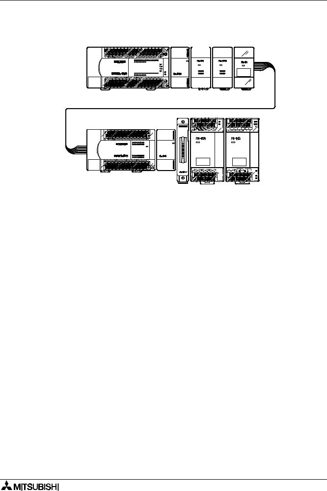
FX2N Series Programmable Controllers Introduction 1
Figure 1.6:
|
|
|
|
|
|
|
|
|
|
|
|
|
|
|
|
|
|
|
|
|
|
|
) |
|
|
+ |
, |
|
|
|
|
|
|
|
|
|
|
|
|
|
|
|
|
|
|
|
||||
|
|
|
|
|
|
|
|
|
|
|
|
|
|
|
|
|
|
|
||||
|
|
|
|
|
|
|
|
|
|
|
|
|
|
|
|
|
|
|
||||
|
|
|
|
|
|
|
|
|
|
|
|
|
|
|
|
|
|
|
||||
|
|
|
|
|
|
|
|
|
|
|
|
|
|
|
|
|
|
|
||||
|
|
|
|
|
|
|
|
|
|
|
|
|
|
|||||||||
|
|
|
|
|
|
|
|
|
|
|
|
|
|
|
|
|
|
|
||||
|
|
|
|
|
|
|
|
|
|
|
|
|
|
|
|
|
|
|
|
( |
|
|
|
|
|
|
|
|
|
|
|
|
|
|
|
|
|
|
|
|
|
|
|
|
|
|
|||
|
|
|
|
|
|
|
|
||
|
|
|
|
|
|
|
|||
|
|
|
|
|
|
|
|
|
|
|
|
|
|
|
|
|
|
|
|
|
|
|
|
|
|
|
|
|
|
|
|
|
|
|
|
|
|
|
|
|
|
|
|
|
|
|
|
|
|
|
|
|
|
|
|
|
|
|
|
|
|
|
|
|
|
|
|
|
|
|
|
|
|
|
|
|
|
|
|
|
|
|
|
|
|
|
|
|
|
|
|
|
|
|
|
|
|
|
|
|
|
|
|
|
|
|
|
|
|
|
|
|
|
|
|
||||
|
|
|
|
|
|
|
|
|
|
|
|
|
|
|
|
|
|
|
|
|
||||
|
|
|
|
|
|
|
|
|||||||
|
|
|
|
|
|
|
|
|||||||
|
|
|
|
|
|
|
|
/ |
|
|
|
|
|
|
|
|
|
|
|
|
|
|
|
|
|
|
|
||
|
|
|
|
|
|
. |
|
|
|
|
|
|
||
|
|
|
|
|
|
|
|
|
|
|
|
|
|
|
|
|
|
|
|
|
|
|
|
|
|
|
|
|
|
|
|
|
|
|
|
|
|
|
|
|
|
|
|
|
|
|
|
|
|
|
|
|
|
|
|
|
|
|
|
|
|
|
|
|
|
|
|
|
|
|
|
|
|
|
|
|
|
|
|
|
|
|
|
|
|
|
|
|
|
|
|
|
|
|
|
|
|
|
|
|
|
|
||
|
|
|
|
|
|
|
|
|
|
|
|
|
||
− |
|
|
|
|
|
|
|
|
|
0 |
|
|
|
|
|
|
|
|
|
|
|
|
|
|
|
|
|
|
|
|
|
|
|
|
|
|
|
|
|
|
|
|
|
|
|
|
|
|
|
|
|
|
|
|
|
|
|
|
|
|
|
|
|
|
|
|
|
|
|
|
|
|
||
|
|
|
|
|
|
|
|
|
|
|
|
|
|
|
|
|
|
|
|
|
|
|
|
|
|
|
|
|
|
|
|
|
|
|
|
|
|
|
|
|
|
|
|
|
|
|
|
|
|
|
|
|
|
|
|
|
|
|
|
|
|
|
|
|
|
|
|
|
|
|
|
|
|
|
|
|
|
|
|
|
|
|
|
|
|
|
|
|
|
|
|
|
|
|
|
|
|
|
|
|
|
|
|
|
|
|
|
|
|
|
|
|
|
|
|
|
|
|
|
|
|
|
|
|
|
|
|
|
|
|
||||
|
|
|
|
|
|
|
|
|
|
|
|
|
|
|
|
|
|
|
|
|
|
||
|
|
|
|
|
|
|
|
|
|
|
|
1
|
|
|
|
|
|
|
|
|
|
|
|
|
|
|
|
|
|
Table 1.15: ENG - System Configuration Example |
|
|
|
|
|
|
||||||
FRE |
- Exemple Configuation du systéme |
|
|
|
|
|
||||||
GER - Systemkonfiguration Beispiel |
|
|
|
|
|
|
||||||
ITL |
- Esempio Configurazione del sistema |
|
|
|
|
|
||||||
ESP |
- Ehemplo Configuración del sistema |
|
|
|
|
|
||||||
|
|
|
|
|
|
|
|
|
|
|
|
|
UNIT |
|
ADDRESSABLE I/O |
24V DC SERVICE SUPPLY |
|
5V DC |
POWER |
||||||
|
|
|
|
|
|
|
|
|
|
|
AC/DC |
|
|
|
X |
Y |
X/Y |
SUM I/O |
|
TABLE |
SUM |
|
TABLE |
SUM |
|
|
|
|
|
|
|
|
|
|
|
|
|
|
ΠFX2N-48MR-ES/UL |
|
24 |
24 |
- |
|
|
1.13 |
|
1.11 Þ |
+ 290 mA |
Table 4.1 |
|
|
|
|
|
AC 50 VA |
||||||||
|
|
|
|
|
|
|
(48M¶) |
|
|
|
|
|
|
|
|
|
|
X=8 |
|
|
|
|
|
|
|
•FX2N-16EYR-ES/UL |
- |
16 |
- |
|
|
- |
0 mA |
- |
||||
|
Axis A = |
+ 185 mA |
||||||||||
Y = 24 |
|
|||||||||||
|
|
|
|
|
|
24 |
|
|
|
|
||
ŽFX2N-8EX-ES/UL |
|
8 |
- |
- |
Þ |
|
|
- |
0 mA |
- |
||
|
|
|
Axis B = 8 |
|
||||||||
|
|
|
|
|
|
|
|
|
|
|
|
|
|
|
|
|
|
|
|
Þ |
|
|
|
|
|
•FX2N-8EYR-ES/UL |
|
- |
8 |
- |
|
|
|
- |
0 mA |
- |
||
|
|
|
|
|
||||||||
|
|
|
|
|
|
|
|
|
|
|
|
|
•FX0N-3A |
|
- |
- |
8 |
- |
|
1.4 Þ |
- 90 mA |
1.5 Þ |
-30 mA |
- |
|
|
|
|
|
|
|
|
|
|
|
|
|
|
ß |
|
ß |
ß |
ß |
|
|
|
95 mA |
|
|
+ 260 mA |
|
|
|
|
|
|
|
|
|
|
||||
|
|
|
|
+95 mA |
|
|
+ 260 mA |
|
||||
|
|
|
|
|
|
|
|
OK! |
|
|
OK! |
|
|
|
|
|
|
|
|
|
|
|
|
|
|
‘ FX2N-32ER-ES/UL |
|
16 |
16 |
- |
|
|
1.12 |
|
1.11 Þ |
+ 690 mA |
Table 4.1 |
|
|
X =16 |
|
(32E¶) |
|
AC 35 VA |
|||||||
|
|
|
|
|
|
+ 150 mA |
|
|
|
|||
’ FX2N-16EX-ES/UL |
|
16 |
- |
- |
Y = 0 |
|
Axis A = 0 |
- |
0 mA |
- |
||
|
|
|
|
|
Þ |
|
Axis B = 16 |
|
|
|
|
|
“ FX2N-CNV-IF |
|
- |
- |
- |
|
|
|
- |
0 mA |
- |
||
|
|
|
Þ |
|
||||||||
|
|
|
|
|
|
|
|
|
|
|
|
|
ß FX ONLY ß |
|
|
|
|
|
|
|
|
|
|
|
|
|
|
|
|
|
|
|
|
|
|
|
|
|
” FX-4AD |
|
- |
- |
8 |
- |
|
- |
0 mA |
1.6 Þ |
- 30 mA |
DC24V 50 mA |
|
|
|
|
|
|
|
|
|
|
|
|
|
|
• FX-1HC |
|
- |
- |
8 |
- |
|
- |
0 mA |
1.6 Þ |
- 70 mA |
- |
|
|
|
|
|
|
|
|
|
|
|
|
|
|
|
|
64 |
64 |
24 |
|
|
|
+ 150 mA |
|
|
+590 mA |
|
|
|
|
|
|
|
|
|
|
|
|
|
|
|
|
152 (< 256 OK!) + |
|
|
|
+ 150 mA |
|
|
+ 590 mA |
|
||
|
|
|
|
|
OK! |
|
|
OK! |
|
|||
|
|
|
|
|
|
|
|
|
|
|
||
|
|
|
|
|
|
|
|
|
|
|
|
|
1-16
FX2N Series Programmable Controllers |
Terminal Layout 2 |
1 |
ENG |
FRE |
GER |
ITL |
ESP |
Introduction |
Introduction |
Einleitung |
Introduzione |
Introducción |
2 |
Terminal |
Occupation |
Klemmen- |
Assegnazione |
Ocupaciones |
Layouts |
des bornes |
belegungen |
dei morsetti |
de bornas |
|
|
|
|
|
3
4
5
6
7
8
Installation |
Installation |
Installation |
Installazione |
Instalación |
|
Notes |
|||||
|
|
|
|
||
|
|
|
|
|
|
|
|
|
|
|
|
Power supply |
Alimentation |
Spannungs- |
Alimentazione |
Alimentación |
|
en tension |
versorgung |
della tensione |
de tensión |
||
|
|||||
|
|
|
|
|
|
|
|
|
|
|
|
Inputs |
Entrées |
Eingänge |
Ingressi |
Entradas |
|
|
|
|
|
|
|
|
|
|
|
|
|
Outputs |
Sorties |
Ausgänge |
Uscite |
Salidas |
|
|
|
|
|
|
|
|
|
|
|
|
|
Diagnostics |
Diagnostic |
Fehlerdiagnose |
Diagnostica |
Diagnóstico de |
|
d’erreurs |
fallos y errores |
||||
|
|
|
|||
|
|
|
|
|
|
|
|
|
|
|
|
Index |
Index |
Stichwort- |
Indice |
Indice |
|
verzeichnis |
analitico |
alfabético |
|||
|
|
||||
|
|
|
|
|
2-1

FX2N Series Programmable Controllers |
Terminal Layout 2 |
2-2
FX2N Series Programmable Controllers |
Terminal Layout 2 |
2.
ENG
FRE
GER
ITL
ESP
Terminal layouts
The following selection of terminal layouts are taken from the FX2N product range.
Note: All layouts are diagrammatic only and are only intended to aid the creation of wiring diagrams. Some units over 80 I/O do not convienently fit on the page, hence the terminal rails have been split to suit.
Occupation des bornes
Les occupations des bornes représentées ci-après constituent une sélection parmi la gamme de produits de la sérieFX2N.
Remarque: Tous les schémas d’occupation des bornes sont de simples représenta-tions schématiques destinées à servir d’aide pour l’établissement des plans de câblage. Etant donné que les appareils dotés de plus de 80 entrées/sorties n’ont pas pu être disposés à l’échelle, les occupations des bornes de ces appareils ont été divisées en deux parties.
Klemmenbelegungen
Die nachfolgend dargestellten Klemmenbelegungen zeigen eine Auswahl aus dem Produktbereich der FX2N-Serie.
Hinweis: Alle Klemmenpläne sind nur schematisch dargestellt und sollen als Hilfe zur Erstellung der Verdrahtungspläne dienen. Da die Geräte mit mehr als 80 Ein-/Aus-gängen nicht maßstabsgetreu angeordnet werden konnten, wurden die An-schlußbelegungen dieser Geräte zweigeteilt.
Assegnazione dei morsetti
L’assegnazione dei morsetti di seguito rappresenta una selezione della gamma di prodotti della serie FX2N.
Avvertenza: Tutti gli schemi morsetti sono riportati solo in forma schematica e inten-dono essere di aiuto nell’esecuzione degli schemi di cablaggio. Poiché non si è potuto disporre su scala gli apparecchi con più di 80 ingressi/uscite, abbiamo bipartito gli allacciamenti di questi apparecchi.
Ocupaciones de bornas
Las ocupaciones de bornas expuestas a continuación muestran una selección del sector de productos de las series FX2N.
Nota: Todos los esquemas de bornas se representan sólo esquemáticamente y deberán ser considerados como ayuda para la elaboración de los esquemas de cableado. Debido a que las unidades con más de 80 entradas/salidas no se pueden disponer en escala, la exposición de las ocupaciones de conexiones de estas unidades se ha realizado dividida en dos secciones.
2-3

FX2N Series Programmable Controllers |
Terminal Layout 2 |
2.1
ENG
FRE
GER
ITL
Relay output, 24V DC input MPU’s - Main Processing Unit (base units)
Appareils de base avec sorties de relais et entrées 24V CC
Grundgeräte mit RelaisAusgängen und DC 24VEingängen
Apparecchi base con uscite relè e ingressi 24V DC


|
|
|
|
|
|
|
|
|
|
|
|
|
|||||
|
Unidades base con Salidas |
|
|
|
|
|
|||||||
ESP |
|
|
|
|
|
|
|||||||
|
de relé y Entradas de 24 V |
|
|
|
|
|
|
||||||
|
CC |
|
|
|
|
||||||||
|
|
|
|
|
|
||||||||
|
|
|
|
|
|
||||||||
|
|
|
|
|
|||||||||
|
|
|
|
|
|
||||||||
|
|
|
|
|
|
|
|
|
|
|
|
|
|
|
|
|
|
|
|
|
|
|
|||||
|
|
|
|
|
|
|
|
||||||
|
|
|
|
|
|
|
|
|
|
||||
|
|
|
|
||||||||||
|
|
|
|
|
|
|
|
|
|
|
|
|
|
|
|
|
|
|
|
|
|
||||||
|
|
|
|
|
|
|
|
|
|||||
|
|
|
|
|
|
|
|
|
|
|
|
||
|
|
|
|
|
|
|
|
|
|
||||
|
|
|
|
|
|
|
|
|
|
||||
|
|
|
|
|
|
|
|
|
|
|
|
||
|
|
|
|
|
|
|
|
||||||
|
|
|
|
|
|
|
|
|
|
|
|
||
|
|
|
|
|
|
|
|||||||
|
|
|
|
|
|
|
|
|
|
|
|
|
||
|
|
|
|
|
|
|
|
|
|
||
2-4
 Loading...