


LVP-X400BU

EN – 1
ENGLISH
X400B
X390
LCD
Projector
User Manual
MODEL LVP-X400BU / LVP-X390U
FRANÇAIS
DEUTSCH
ITALIANO
ESPAÑOL
EN – 2
RISK OF ELECTRIC SHOCK
DO NOT OPEN
CAUTION
CAUTION: TO REDUCE THE RISK OF ELECTRIC SHOCK,
DO NOT REMOVE COVER (OR BACK)
NO USER-SERVICEABLE PARTS INSIDE
REFER SERVICING TO QUALIFIED
SERVICE PERSONNEL.
The lightning flash with arrowhead symbol, within an equilateral triangle, is intended
to alert the user to the presence of uninsulated “dangerous voltage” within the
product’s enclosure that may be of sufficient magnitude to constitute a risk of electric
shock.
The exclamation point within an equilateral triangle is intended to alert the user to the
presence of important operating and maintenance (servicing) instructions in the litera-
ture accompanying the appliance.
WARNING:
TO PREVENT FIRE OR SHOCK HAZARD, DO NOT EXPOSE THIS APPLIANCE TO RAIN OR MOISTURE.
CAUTION:
TO PREVENT ELECTRIC SHOCK, DO NOT USE THIS (POLARIZED) PLUG WITH AN EXTENSION
CORD, RECEPTACLE OR OTHER OUTLET UNLESS THE BLADES CAN BE FULLY INSERTED TO
PREVENT BLADE EXPOSURE.
NOTE:
SINCE THIS PROJECTOR IS PLUGGABLE EQUIPMENT, THE SOCKET-OUTLET MUST BE IN-
STALLED NEAR THE EQUIPMENT AND SHOULD BE EASILY ACCESSIBLE.
WARNING
Use the attached specified power supply cord. If you
use another power-supply cord, it may cause interfer-
ence with radio and television reception.
Use the attached RGB cable, RS-232C cable with this
equipment so as to keep interference within the limit
of a FCC Class A device.
This apparatus must be grounded.
The projector automatically shuts off when the
lamp is used up in about 2,000 hours and cannot
be used until the lamp is replaced and the
internal timer is reset. See page 23.
DO NOT LOOK DIRECTLY INTO THE LENS
WHEN PROJECTOR IS IN THE POWER ON
MODE.
When using the projector in Europe
COMPLIANCE NOTICE
This LCD - Video Projector complies with the
requirements of the EC Directive 89/336/EEC “EMC
Directive” as amended by Directive 93/68/EEC and
73/23/EEC “Low Voltage Directive” as amended by
Directive 93/68/EEC.
The electro-magnetic susceptibility has been chosen
at a level that gains proper operation in residential
areas, on business and light industrial premises and
on small-scale enterprises, inside as well as outside
of the buildings. All places of operation are
characterised by their connection to the public low
voltage power supply system.
WARNING
Use the attached RGB cable or RS-232C cable with
this equipment so as to keep interference within the
limits of a EN55022 Class B and EN55013. Please
follow WARNINGS instructions.

EN – 3
ENGLISH
Contents
Important safeguards.......................................................................... 4
Overview ................................................................................................ 6
Using the remote control ..................................................................... 8
Battery installation ......................................................................................................... 8
Installation ........................................................................................... 9
Basic connections ............................................................................... 10
Projector + AV equipment............................................................................................. 10
Projector + DVD player or HDTV decoder ................................................................... 10
Projector + personal computer ...................................................................................... 11
Preparing the projector for operation ............................................... 12
To operate projector power ON.......................................................... 13
Menu operation .................................................................................. 15
Picture adjustment............................................................................. 18
Specification of RGB signals in each computer mode of the projector ....................... 20
Advanced feature for presentation ................................................... 21
Expand ........................................................................................................................... 21
PinP (Picture in Picture) ............................................................................................... 21
Still ................................................................................................................................. 21
Mouse remote control .................................................................................................... 22
Lamp replacement ............................................................................. 23
Maintenance ....................................................................................... 24
Troubleshooting .................................................................................. 25
Indicators ............................................................................................ 26
Specifications ...................................................................................... 27
Kensington Lock ............................................................................................................ 27
Connectors ..................................................................................................................... 28
Dimensional drawings .................................................................................................. 28
What’s included in the box............................................................................................ 28
Replacement part .......................................................................................................... 28
Trademark, Registered trademark
Macintosh is trademark or registered trademark of Apple Computer Inc.
IBM and PS/2 are trademarks or registered trademarks of International Business Machines Corporation.
Windows is trademark or registered trademark of Microsoft Corporation.
MicroSaver and Kensington are registered trademarks of Kensington Technology Group.
Other brand or product names are trademarks or registered trademarks of their respective holders.

EN – 4
Important safeguards
Please read all these instructions regarding your LCD
projector and retain them for future reference. Follow
all warnings and instructions marked on the LCD pro-
jector.
1. Read instructions
All the safety and operating instructions should
be read before the appliance is operated.
2. Retain instructions
The safety and operating instructions should be
retained for future reference.
3. Warnings
All warnings on the appliance and in the oper-
ating instructions should be adhered to.
4. Instructions
All operating instructions must be followed.
5. Cleaning
Unplug this projector from the wall outlet be-
fore cleaning it. Do not use liquid aerosol clean-
ers. Use a damp soft cloth for cleaning.
6. Attachments and equipment
Never add any attachments and/or equipment
without the approval of the manufacturer as
such additions may result in the risk of fire, elec-
tric shock or other personal injury.
7. Water and moisture
Do not use this projector near water or in con-
tact with water.
8. Accessories
Do not place this projector on an unstable cart,
stand, tripod, bracket or table. Use only with a
cart, stand, tripod bracket, or table recom-
mended by the manufacturer or sold with the
projector. Any mounting of the appliance should
follow the manufacturer's instructions and
should use a mounting accessory recommended
by the manufacturer.
10. Power sources
This projector should be operated only from the
type of power source indicated on the marking
label. If you are not sure of the type of power,
please consult your appliance dealer or local
power company.
11. Power-cord protection
Power-supply cords should be routed so that they
are not likely to be walked on or pinched by items
placed upon or against them. Pay particular at-
tention to cords at plugs, convenience receptacles,
and points where they exit from the appliance. Do
not put the power cord under a carpet.
12. Overloading
Do not overload wall outlets and extension cords
as this can result in a fire or electric shock.
13. Objects and liquids
Never push objects of any kind through open-
ings of this projector as they may touch danger-
ous voltage points or short-out parts that could
result in a fire or electric shock. Never spill liq-
uid of any kind on the projector.
14. Servicing
Do not attempt to service this projector your-
self. Refer all servicing to qualified service per-
sonnel.
15. Damage requiring service
Unplug this projector from the wall outlet and
refer servicing to qualified service personnel un-
der the following conditions:
(a) If the power-supply cord or plug is dam-
aged.
(b) If liquid has been spilled, or objects have
fallen into the projector.
(c) If the projector does not operate normally
after you follow the operating instructions.
Adjust only those controls that are covered
by the operating instructions. An improper
adjustment of other controls may result
in damage and may often require exten-
sive work by a qualified technician to re-
store the projector to its normal operation.
(d) If the projector has been exposed to rain
or water.
(e) If the projector has been dropped or the
cabinet has been damaged.
(f) If the projector exhibits a distinct change
in performance - this indicates a need for
service.
16. Replacement parts
When replacement parts are required, be sure
that the service technician has used replacement
parts specified by the manufacturer or parts
having the same characteristics as the original
part. Unauthorized substitutions may result in
fire, electric shock or other hazards.
17. Safety check
Upon completion of any service or repair to this
projector, ask the service technician to perform
safety checks determining that the projector is
in a safe operating condition.
An appliance and cart combination should be
moved with care. Quick stops, excessive force and
uneven surfaces may cause the appliance and
cart combination to overturn.
9. Ventilation
Slots and openings in the cabinet are provided
for ventilation, ensuring reliable operation of the
projector and to protect it from overheating. Do
not block these openings or allow them to be
blocked by placing the projector on a bed, sofa,
rug, or bookcase. Ensure that there is adequate
ventilation and that the manufacturer's instruc-
tions have been adhered to.

EN – 5
ENGLISH
WARNING:
Unplug immediately if there is something
wrong with your projector.
Do not operate if smoke, strange noise or odor comes
out of your projector. It might cause fire or electric
shock. In this case, unplug immediately and contact
your dealer.
Never remove the cabinet.
This projector contains high voltage circuitry. An
inadvertent contact may result in an electric shock.
Except as specifically explained in the Owner's
Guide, do not attempt to service this product
yourself. Please contact your dealer when you want
to fix, adjust or inspect the projector.
Do not modify this equipment.
It can lead to fire or electric shock.
If you break or drop the cabinet.
Do not keep using this equipment if you break or
drop it. Unplug the projector and contact your dealer
for inspection. It may lead to fire if you keep using
the equipment.
Do not face the projector lens to the sun.
It can lead to fire.
Use correct voltage.
If you use incorrect voltage, it can lead to fire.
Do not place the projector on uneven
surface.
Place the projection on a leveled and stable surface
only. Please do not place equipment on unstable
surfaces.
Do not look into the lens when it is
operating.
It may hurt your eyes.Never let children look into
the lens when it is on.
Do not turn off the main power abruptly or
unplug the projector during operation.
It can lead to lamp breakage, fire, electric shock or
other trouble. It is best to wait for the fan to turn off
before turning main power off.
Do not touch Air outlet grill and Bottom
plate which becomes hot.
Do not touch them or put other equipment in front of
Air outlet grill. The heated Air outlet grill and Bot-
tom plate may cause injury or damage to other equip-
ment. Also, do not set the projector on the desk which
is easily affected by heat.
Clean the air-filter once a month.
Clean the air-filter frequently. If the filter or ventila-
tion slots become clogged with dirt or dust, the tem-
perature inside of the projector may rise and cause
some troubles, such as damage of inside parts, and
shortening the life of panel.
Place of installation
For safety’s sake, refrain from setting the projector at
any place subjected to high temperature and high
humidity. Please maintain an operating temperature,
humidity, and altitude as specified below.
• Operating temperature: between +41°F (+5°C) and
+104°F (+40°C)
• Operating humidity: between 30 and 90%
• Never put any heat-producing device under the pro-
jector so that the projector does not overheat.
• Do not attach the projector to a place that is un-
stable or subject to vibration.
• Do not install the projector near any equipment that
produces a strong magnetic field. Also refrain from
installing near the projector any cable carrying a
large current.
• Place the projector on a solid, vibration free sur-
face: otherwise it may fall, causing serious injury
to a child or adult, and serious damage to the prod-
uct.
• Do not stand the projector: it may fall, causing se-
rious injury and damage to the projector.
• Place the projector within a slope of ±15˚. Slanting
the projector more than ±15˚ may cause trouble or
explosion of the lamp.
• Do not place the projector near air-conditioning unit
or heater to avoid hot air to the exhaust and venti-
lation hole of the projector.
COMPLIANCE NOTICE OF FCC
This equipment has been tested and found to comply with the limits for a Class A digital device, pursuant to Part
15 of the FCC Rules. These limits are designed to provide reasonable protection against harmful interference
when the equipment is operated in a commercial environment. This equipment generates, uses, and can radiate
radio frequency energy and, if not installed and used in accordance with the instruction manual, may cause
harmful interference to radio communications. Operation of this equipment in a residential area is likely to cause
harmful interference in which case the user will be required to correct the interference at his own expense.
This digital apparatus does not exceed the Class A limits for radio noise emissions from digital apparatus as set
out in the interference-causing equipment standard entitled “Digital Apparatus”, ICES-003 of the Department of
Communications.
Changes or modifications not expressly approved by Mitsubishi could void the user's authority to operate this equipment.
COMPLIANCE NOTICE OF INDUSTRY CANADA
This Class A digital apparatus complies with Canadian ICES-003.
EN – 6
Overview
LAMP
VOLUME
ZOOM/
FOCUS
TEMP
VIDEO
ENTER
COMPUTER
MUTE
AUTO
POSITION
MENU
1
2
3
4
5
11
10
9
8
7
6
14 13 12
4
7
65
1
2
3
89 10
1
56 7
L
R
S-VIDEO
VIDEO
AUDIO
MAIN
REMOTE
AC IN
AUDIO OUT
VIDEO 1
IN
VIDEO 2
IN
COMPUTER OUT
OI
AUDIO 2 IN
COMPUTER 2 IN
AUDIO 1 IN
USB
DIGITAL
ANALOG
INPUT SELECT
COMPUTER 1 IN
RS-232C
2
3
4
89
1011121314
15
16
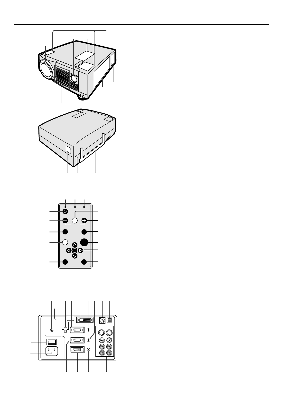
Control panel
Terminal board
1 Air inlet grill (Front)
2 Terminal board
3 Air outlet grill
4 Speaker (Left/Right)
5 Control panel
6 Remote control sensor (Front)
7 Lens
8 Remote control sensor (Rear)
9 Kensington Security Lock Standard
connector
10 Easy-carry handle
1 Power button
2 – (VOLUME) button
3 COMPUTER button
4 MENU button
5 AUTO POSITION button
6 MUTE button
7 Direction buttons
8 ENTER button
9 VIDEO button
10 + (VOLUME) button
11
ZOOM/FOCUS button
12 TEMP (temperature) indicator
13 LAMP indicator
14 Power indicator
1 Main power
I : ON
O : OFF
2 Ground terminal
3 Power jack
4 COMPUTER 2 IN terminal (D-SUB mini 15P)
5 COMPUTER OUT terminal (D-SUB mini 15P)
6 AUDIO OUT jack
7 Video/audio input terminals
8 USB Terminal
9 RS-232C (DIN 8P) terminal
10 COMPUTER 2 AUDIO IN jack
11 COMPUTER 1 AUDIO IN jack
12 COMPUTER 1 IN terminal (DVI-D24P)(For
LVP-X400BU only)
13 COMPUTER 1 IN terminal (D-SUB mini 15P)
14 INPUT SELECT switch (For LVP-X400BU only)
15 Reset button
16 Wired remote control (REMOTE) jack
EN – 7
ENGLISH
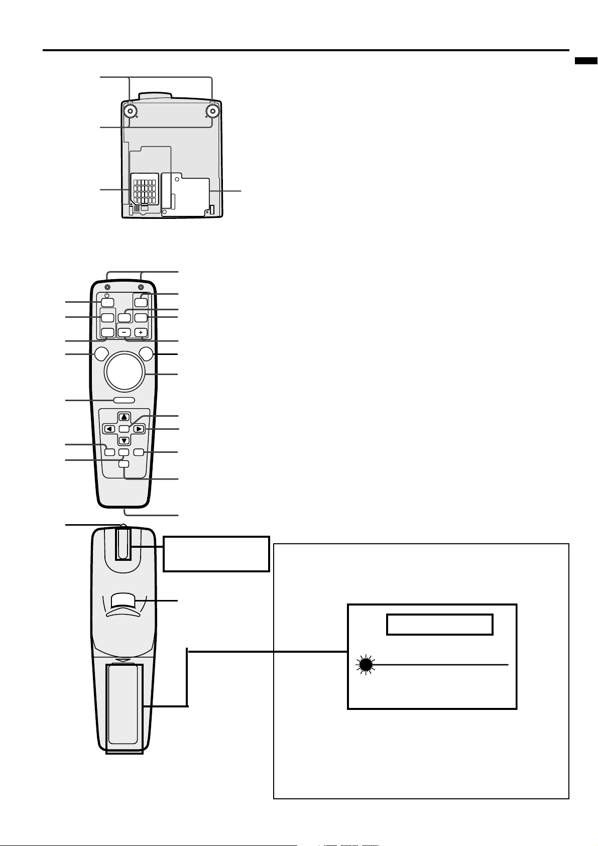
Bottom side
1
3
2
4
1 Release buttons (Left/Right)
2 Adjustment foot (Left/Right)
3 Air inlet cover
4 Lamp cover
Caution:
Do not replace the lamp right after using the projector. The
lamp will be very hot.
ENTER
RIGHT CLICK
LASER
COMPUTER
VIDEO
ZOOM/
FOCUS
KEYSTONE
VOLME
AUTO
POSITION
MENU
P in P
MUTE
EXPAND STILL
1
2
3
4
5
6
7
17
19
18
16
15
14
13
12
10
21
20
11
9
8
Remote control
1 Power button
2 COMPUTER button
3 AUTO POSITION button
4 MENU button
5 Right click button (For mouse)
6 EXPAND button
7 PinP button
8 Wired remote control jack
9 MUTE (Audio/Video) button
10 STILL button
11
Direction buttons
1
2 ENTER button
13 Mouse pointer
14 LASER button
15 + , – (VOLUME) buttons
16 ZOOM/FOCUS button
17 VIDEO button
18 KEYSTONE button
19 Remote control transmitter
20 Laser aperture
21 Left click button (For mouse)
• Pressing LASER button emits the laser beam about
1 minute. Release LASER button and press it again
if you wish to emits the laser beam.
About laser beam
This remote control is class 2 (max. output 1 mW laser diode
640 - 660 nm) laser equipment.
Beam Divergence : 6m distance about 10.0mm x 10.0mm (±6.0mm)
LASER RADIATION
DO NOT STARE INTO BEAM
WAVE LENGTH : 640 - 660 nm
MAX OUTPUT : 1 mW
CLASS 2 LASER PRODUCT
IEC 60825-1:1993+A1:1997
CAUTION
CAUTION :
• Pressing the LASER button provided remote control emits
laser beam. Do not look into the beam light directly. Do not
point the laser beam at people. Looking the laser beam directly
may damage eyesight.
• Use of controls or adjustments or procedures other than those
specified herein may result in hazardous radiation exposure.
AVOID EXPOSURE -LASER
RADIATION IS EMITTED
FROM THIS APERTURE.
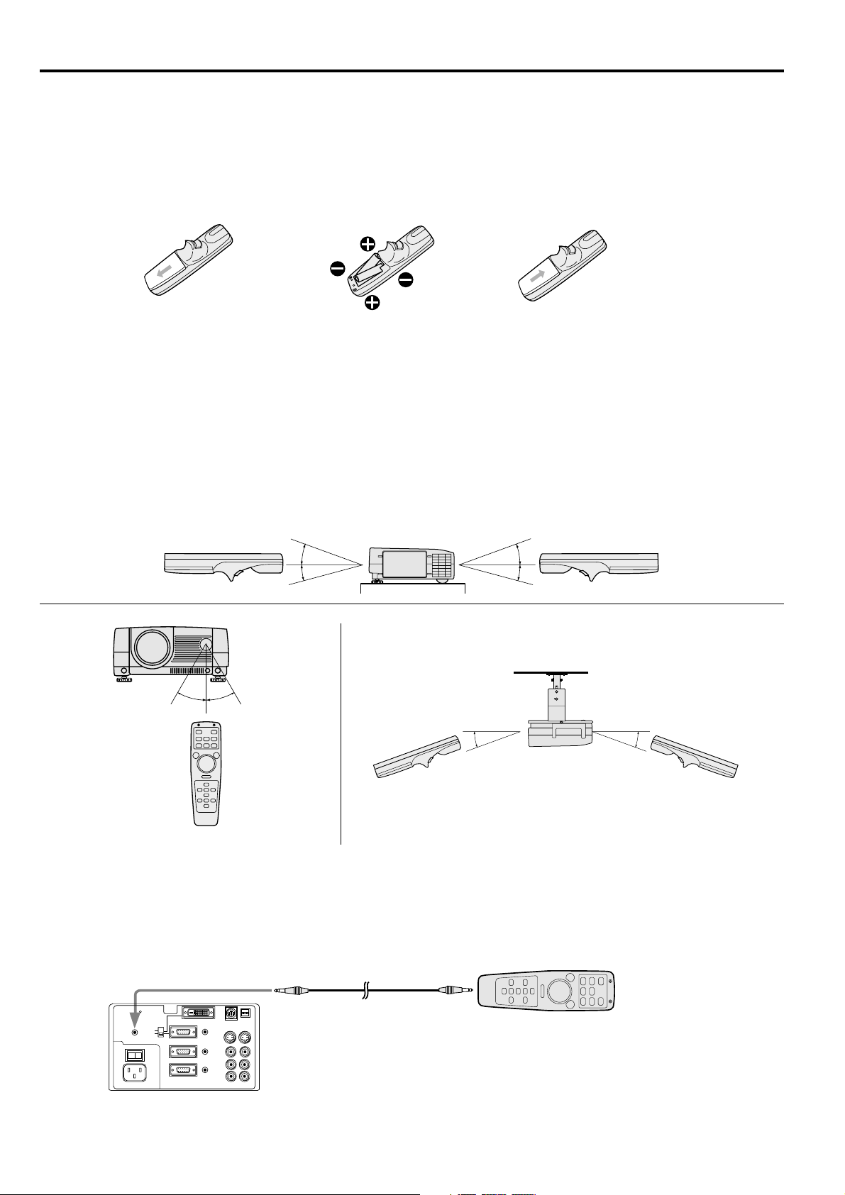
EN – 8
Battery installation
Use two AA size batteries.
1. Remove the back cover of the remote control by pushing the battery compartment door in the direction of the
arrow.
2. Load the batteries making sure that they are positioned correctly (+ to +, and - to -).
3. Replace the back cover.
Important:
• Do not use a new battery with an old one.
• Load batteries in the correct position.
• Do not heat, take apart, or throw batteries into fire.
• Do not try to recharge batteries. Do not use rechargeable batteries.
• If the solution of batteries comes in contact with your skin or clothes, rinse with water. If the solution comes
in contact with your eyes, rinse them with water and then consult your doctor.
Operation area (for wireless control system)
The range for operation is about 10 m (about 32 feet) when the remote control points to the projector. The dis-
tance to the screen back to the projector must be less than 7 m (about 23 feet). Depending on the type of the
screen, the distance will be different.
Important:
Avoid the direct sunlight or fluorescent light to the remote control sensor. Also keep the distance of more than 2 m
(6.5") between the remote control sensor and fluorescent lamp on the remote control may not work correctly.
Using the wired remote control
Attached remote control for this projector can be used as a wired remote control with remote control cable. Wired
remote control is useful for operating in a distance or outside of the operating area.
20˚
15˚
20˚
15˚
30˚30˚
20˚ 20˚
12 3
L
R
S-VIDEO
VIDEO
AUDIO
MAIN
REMOTE
AC IN
AUDIO OUT
VIDEO 1
IN
VIDEO 2
IN
COMPUTER OUT
OI
AUDIO 2 IN
COMPUTER 2 IN
AUDIO 1 IN
USB
DIGITAL
ANALOG
INPUT SELECT
COMPUTER 1 IN
RS-232C
• When the remote control is connected with remote
control cable, it does not work as a wireless
remote control.
• When you need a longer cable, use a pin-pin cable.
• When using the wired remote control, the laser beam may be darker. It is normal.
Using the remote control
´ EN – 9
ENGLISH
Installation
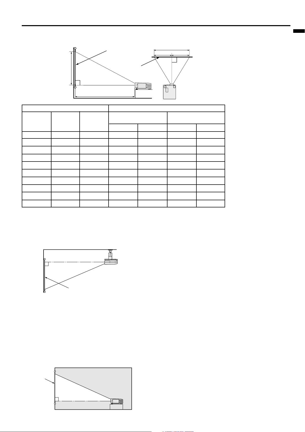
Orientation of the projector
Picture size can be set by changing the distance between the screen and the projector.
Front projection
To find the approximate distance
between the projector and screen:
Multiply the width of the screen
x 1.9 (min.) , Multiply the width of
the screen x 2.4 (max.).
• Refer to the chart for recom-
mended distances in maximum
zoom and minimum zoom.
SCREEN
Front projection, ceiling mount
For ceiling mount, you need the ceiling mount kit.
Ask a specialist for installation. For more details,
consult your dealer.
• When using the ceiling mount, set IMAGE RE-
VERSE in the INSTALLATION menu to MIR-
ROR INVERT. See Page 16.
• Projected images may appear darker when the
unit is used as a ceiling installation than when it
is used in the tabletop position. This does not
signify a product malfunction.
Rear projection
Ask a specialist for installation. For more details,
consult your dealer.
SCREEN
• For rear projection, set IMAGE REVERSE in the
INSTALLATION menu to MIRROR. See Page 16.
Caution:
• Placing the projector on a carpet reduces ventila-
tion from the fan at the bottom and might cause
problems. Place a hard board or similar item
under the projector to facilitate ventilation of the
unit.
• Place the projector more than 20 in. from the wall
to prevent blocking the intake, exhaust slots and
ventilation of this projector because hot air comes
out of it.
• Do not use the projector under the following
circumstances, which may cause fire or electric
shock.
• in a dusty or humid place
• while the projector is lying sideways or upside
down
• near a heater
• in a kitchen or oily, smoky or damp place
• in direct sunlight
• with high temperature, such as a closed car
• where the temperature is lower than 41°F or
higher than 104°F
Important:
• Do not put stress on the lens, as this may cause
damage.
Screen
Screen
Width
Height
A
A=B
B
L
(between the screen and the
head of the projector)
• The above numbers are approximate, and may be slightly different from the actual measurements.
Diagonal size
(inch)
40 "
60 "
80 "
100 "
120 "
140 "
160 "
180"
200 "
300 "
Height
(inch)
24 "
36 "
48 "
60 "
72 "
84 "
96 "
108 "
120 "
180 "
Width
(inch)
32 "
48 "
64 "
80 "
96 "
112 "
128 "
144 "
160 "
240 "
Screen
Distance from screen (L) / (approximate)
Maximum
zoom (min.)
(cm)
155
235
315
394
474
554
634
714
794
1194
(cm)
195
296
396
496
597
697
797
898
998
–
(inch)
61 "
92 "
124 "
155 "
187 "
218 "
250 "
281 "
312 "
470 "
(inch)
77 "
116 "
156 "
195 "
235 "
274 "
314 "
353 "
393 "
–
Minimum
zoom (max.)
EN – 10
Basic connections
This projector can be connected to equipment such as VCRs, video cameras, videodisc players, and personal com-
puters having analog RGB output.
Important:
• Make sure that your equipment is turned off before connection.
• Plug in firmly and unplug by holding the plug, not by pulling the main power cable.
• If connected units are set too close to one another, the image may be affected.
• Refer to the owner's guide of each component for details of connections.
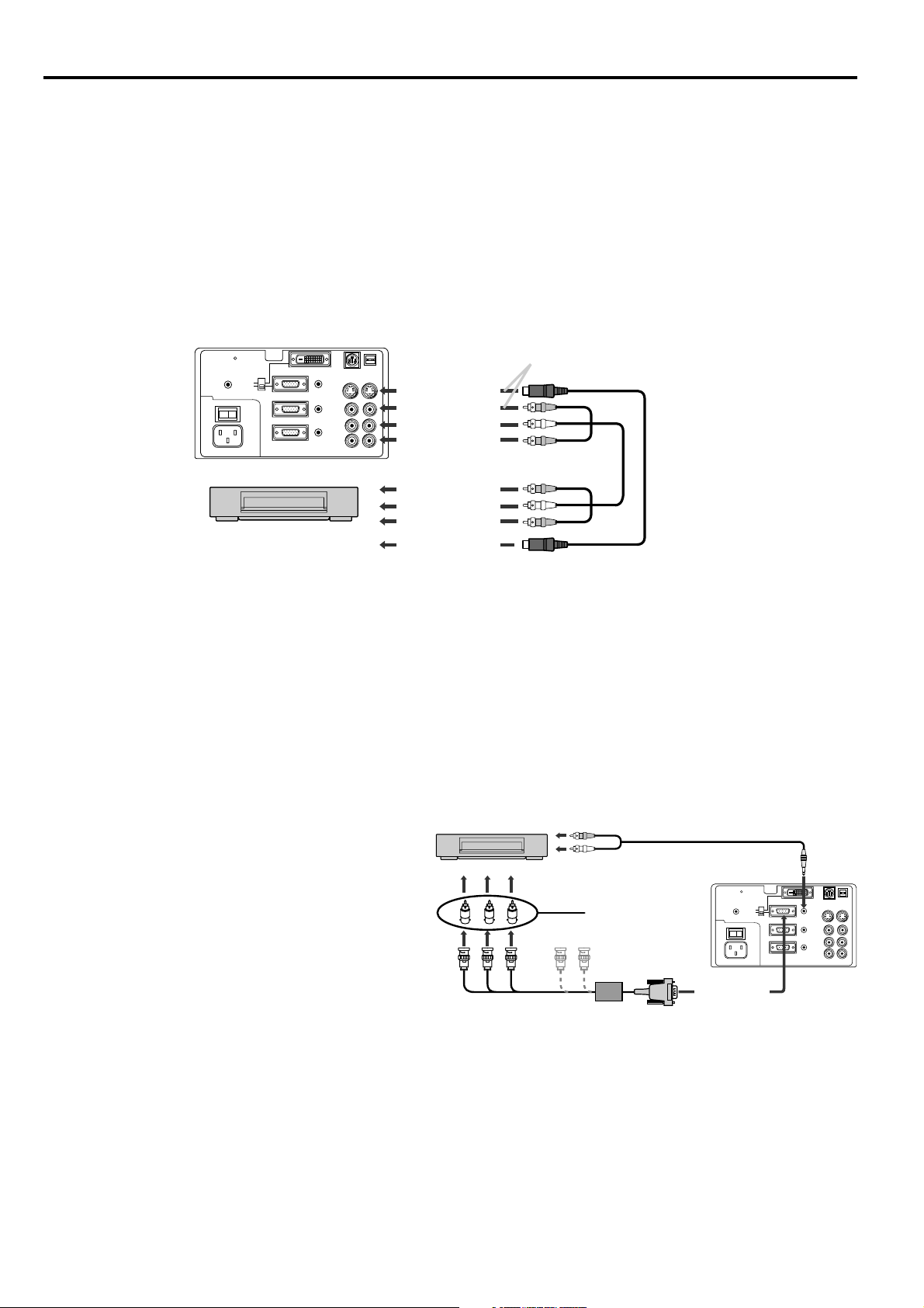
Projector + AV equipment
Important:
• Match the color of video and audio plugs on the AV cable with the connections.
• S-video signals take priority over video signals. If you input both S-video signals and normal video signals at
the same time, the normal video input automatically is inhibited.
L
R
S-VIDEO
VIDEO
AUDIO
MAIN
REMOTE
AC IN
AUDIO OUT
VIDEO 1
IN
VIDEO 2
IN
COMPUTER OUT
OI
AUDIO 2 IN
COMPUTER 2 IN
AUDIO 1 IN
USB
DIGITAL
ANALOG
INPUT SELECT
COMPUTER 1 IN
RS-232C
Connect either one of these.
to S-video input
to S-video output
to video input
to audio input
to video output
to audio output
VCR etc.
L
R
S-VIDEO
VIDEO
AUDIO
MAIN
REMOTE
AC IN
AUDIO OUT
VIDEO 1
IN
VIDEO 2
IN
COMPUTER OUT
OI
AUDIO 2 IN
COMPUTER 2 IN
AUDIO 1 IN
USB
DIGITAL
ANALOG
INPUT SELECT
COMPUTER 1 IN
RS-232C
B G R
C
B
(P
B
)Y C
R
(P
R
)
HD/CS VD
DVD player or HDTV decoder
No connection
BNC - RCA connector
(optional)
Mini D-SUB 15 pin-BNC
conversion cable (optional)
to COMPUTER
AUDIO IN
to AUDIO OUT
AUDIO cable
to COMPUTER
IN (Mini D-SUB
15P)
Projector + DVD player or HDTV decoder
Some DVD players have output terminal for 3 line fitting (Y, CB, CR). When connecting them to the projector,
connect to COMPUTER 1 IN or COMPUTER 2 IN of the projector. In this case, set “ Y, CB , CR” for COMPUTER
INPUT setting in SIGNAL menu.
DVD player generally has SDTV system component
video output (Y, CB, CR) terminals. HDTV decoder has
HDTV system component video output (Y, PB, PR) ter-
minals. When connecting the projector with DVD
player or HDTV decoder, the signal cuircuit
automaticaly applied to either of them. In this case,
the COMPUTER INPUT in the SIGNAL menu be-
comes [Y, CB, CR/Y, PB, PR].
• Y, PB, PR is an example of the terminal names for a HDTV decoder.
• The terminal name is different depending on the connected equipment.
• Use mini D-SUB 15 pin-BNC conversion cable for connection.
• Some DVD players may not project the image correctly.
• When connecting with HDTV equipment which has R, G, B output, set RGB for the COMPUTER INPUT in
the SIGNAL setting menu.
• Change the setting in the SIGNAL menu, when 525p signal is inputted. (Refer to page 20).
• Set the INPUT SELECT switch on the terminal board to ANALOG. (For LVP-X400BU only)
´ EN – 11
ENGLISH
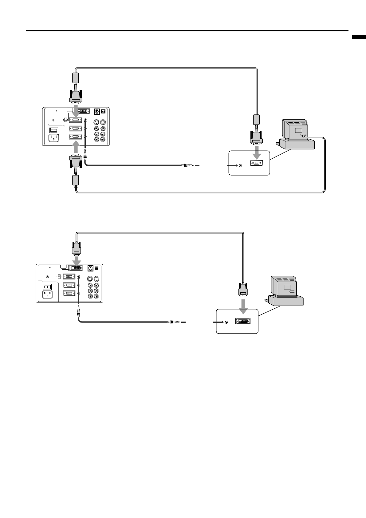
For computer with Mini D-SUB 15P terminal (IBM PC or IBM PC compatibles etc.)
L
R
S-VIDEO
VIDEO
AUDIO
MAIN
REMOTE
AC IN
AUDIO OUT
VIDEO 1
IN
VIDEO 2
IN
COMPUTER OUT
OI
AUDIO 2 IN
COMPUTER 2 IN
AUDIO 1 IN
USB
DIGITAL
ANALOG
INPUT SELECT
COMPUTER 1 IN
RS-232C
AUDIO OUT
MONITOR OUTPUT
to COMPUTER IN (Mini D-SUB 15P)
to COMPUTER AUDIO IN
to monitor
port
to COMPUTER
OUT
to PC audio
output
PC audio cable (option)
When outputting to both a PC monitor and the projector.
RGB cable for PC
RGB cable for PC (option)
computer
• Set the INPUT SELECT switch on the terminal board to ANALOG. (For LVP-X400BU only)
For computer with DVI terminal (For LVP-X400BU only)
L
R
S-VIDEO
VIDEO
AUDIO
MAIN
REMOTE
AC IN
AUDIO OUT
VIDEO 1
IN
VIDEO 2
IN
COMPUTER OUT
OI
AUDIO 2 IN
COMPUTER 2 IN
AUDIO 1 IN
USB
DIGITAL
ANALOG
INPUT SELECT
COMPUTER 1 IN
RS-232C
DVI
to COMPUTER IN (DVI-D24P)
DVI cable (option)
to COMPUTER AUDIO IN
to DVI port
PC audio cable (option)
computer
AUDIO OUT
to PC audio
output
Projector + Personal computer
• Set the INPUT SELECT switch on the terminal board to DIGITAL.
• The signal inputted to the COMPUTER 1 IN (DVI) terminal is not outputted from the COMPUTER OUT terminal.
• Make sure to connect computer with DVI cable before starting computer. If connecting computer with DVI cable after
starting the computer, the image signal may not be outputted from DVI terminal of computer
Important:
• Connectors or analog RGB output adapters may be necessary depending on the PC connected to this projector.
Please contact your dealer.
• The audio input for this projector is a stereo pin jack. Please check the available cable for the audio input
terminal of the computer. Some personal computer may not have the audio output terminal.
For using Macintosh
• A monitor output adapter is necessary for a Macintosh if it has no video port. Please contact your dealer.
• A MAC adapter for RGB cable may be necessary depending on the personal computer connected to this projec-
tor. Please contact your dealer.
About DDC™ (For DVI connection)
The projector complies with VESA™ DDC™ 2B (EDID) specification. If your computer provides DDC™2B (EDID)
function, setup will be done automatically. If your system is Windows
®
98 or higher, your computer supported in
standard. If your system is Windows
®
95 or lower, you must down load the driver from our Internet Home Page for use
this function. Please contact your dealer or Mitsubishi sales office for more details.
 Loading...