


LCD PROJECTOR
MODEL
HC6000
User Manual
HC6000
This User Manual is important to you. Please read it before using your projector.
CAUTION
RISK OF ELECTRIC SHOCK
DO NOT OPEN
CAUTION: TO REDUCE THE RISK OF ELECTRIC
SHOCK, DO NOT REMOVE COVER (OR BACK)
NO USER-SERVICEABLE PARTS INSIDE
REFER SERVICING TO QUALIFIED SERVICE
PERSONNEL.
The lightning flash with arrowhead symbol within an equilateral triangle is intended to alert the user to the presence of uninsulated “dangerous voltage” within the product’s enclosure that may be of sufficient magnitude to constitute a risk of electric shock.
The exclamation point within an equilateral triangle is intended to alert the user to the presence of important operating and maintenance (servicing) instructions in the literature accompanying the appliance.
WARNING:
TO PREVENT FIRE OR SHOCK HAZARD, DO NOT EXPOSE THIS APPLIANCE TO RAIN OR MOISTURE.
CAUTION:
TO PREVENT ELECTRIC SHOCK, DO NOT USE THIS (POLARIZED) PLUG WITH AN EXTENSION CORD, RECEPTACLE OR OTHER OUTLET UNLESS THE BLADES CAN BE FULLY INSERTED TO PREVENT BLADE EXPOSURE.
NOTE:
SINCE THIS PROJECTOR IS PLUGGABLE EQUIPMENT, THE SOCKET-OUTLET SHALL BE INSTALLED NEAR THE EQUIPMENT AND SHALL BE EASILY ACCESSIBLE.
WARNING
Use the attached specified power supply cord. If you use another power supply cord, it may cause interference with radio and television reception.
Use the attached RGB cable and RS-232C cable with this equipment so as to keep interference within the limit of a FCC Class B device.
This apparatus must be grounded.
DO NOT LOOK DIRECTLY INTO THE LENS WHEN THE PROJECTOR IS IN THE POWER ON MODE.
CAUTION
Not for use in a computer room as defined in the Standard for the Protection of Electronic Computer/ Data Processing Equipment, ANSI/NFPA 75.
When using the projector in Europe: COMPLIANCE NOTICE
This projector complies with the requirements of the EC Directive 2004/108/EC “EMC Directive” and 2006/95/EC “Low Voltage Directive”.
The electro-magnetic susceptibility has been chosen at a level that gains proper operation in residential areas, on business and light industrial premises and on small-scale enterprises, inside as well as outside of the buildings. All places of operation are characterised by their connection to the public low voltage power supply system.
WARNING
Use the attached RGB cable and RS-232C cable with this equipment so as to keep interference within the limits of an EN55022 Class B device.
Please follow WARNING instructions.
EN-2
Contents |
|
Important safeguards ........................................................................................................................ |
4 |
Preparing your projector.................................................................................................................... |
6 |
Using the remote control................................................................................................................... |
9 |
Setting up your projector................................................................................................................. |
10 |
Viewing video images...................................................................................................................... |
14 |
Viewing computer images ............................................................................................................... |
22 |
Menu operation ............................................................................................................................... |
25 |
Adjusting projected images............................................................................................................. |
31 |
Advanced features .......................................................................................................................... |
35 |
Replacing the lamp ......................................................................................................................... |
36 |
Maintenance.................................................................................................................................... |
38 |
Accessory air-filter unit.................................................................................................................... |
39 |
Troubleshooting............................................................................................................................... |
40 |
Indicators......................................................................................................................................... |
43 |
Specifications.................................................................................................................................. |
44 |
Note: This symbol mark is for EU countries only.
This symbol mark is according to the directive 2002/96/EC Article 10
Information for users and Annex IV.
Your MITSUBISHI ELECTRIC product is designed and manufactured with high quality materials and components which can be recycled and reused.
This symbol means that electrical and electronic equipment, at their end-of-life, should be disposed of separately from your household waste.
Please, dispose of this equipment at your local community waste collection/recycling centre.
In the European Union there are separate collection systems for used electrical and electronic product.
Please, help us to conserve the environment we live in!
Declaration of Conformity
Model number: |
HC6000 |
Trade name: |
MITSUBISHI ELECTRIC |
Responsible party: |
Mitsubishi Digital Electronics America, Inc. |
|
9351 Jeronimo Road, Irvine, CA 92618 U.S.A |
Telephone number: |
+1-(949) 465-6000 |
This device complies with Part 15 of the FCC Rules. Operation is subject to the following two conditions:
(1)this device may not cause harmful interference, and
(2)this device must accept any interference received, including interference that may cause undesired operation.
Trademark, Registered trademark
HDMI, the HDMI logo and High-Definition Multimedia Interface are trademarks or registered trademarks of HDMI Licensing LLC.
The “HD ready” logo is a trademark of EICTA.
Other brand or product names are trademarks or registered trademarks of their respective holders.
EN-3

Important safeguards
Please read all these instructions regarding your projector and retain them for future reference. Follow all warnings and instructions marked on the projector.
1.Read instructions
All the safety and operating instructions should be read before the appliance is operated.
2.Retain instructions
The safety and operating instructions should be retained for future reference.
3.Warnings
All warnings on the appliance and in the operating instructions should be adhered to.
4.Instructions
All operating instructions must be followed.
5.Cleaning
Unplug this projector from the wall outlet before cleaning it. Do not use liquid aerosol cleaners. Use a damp soft cloth for cleaning.
6.Attachments and equipment
Never add any attachments and/or equipment without the approval of the manufacturer as such additions may result in the risk of fire, electric shock or other personal injury.
7.Water and moisture
Do not use this projector near water or in contact with water.
8.Accessories
Do not place this projector on an unstable cart, stand, tripod, bracket or table. Use only with a cart, stand, tripod, bracket, or table recommended by the manufacturer or sold with the projector. Any mounting of the appliance should follow
the manufacturer’s instructions and should use a mounting accessory recommended by the manufacturer.
An appliance and cart combination should be moved with care. Quick stops, excessive force and uneven surfaces may cause the appliance and cart combination to overturn.
9.Ventilation
Slots and openings in the cabinet are provided for ventilation, ensuring reliable operation of the
projector and to protect it from overheating. Do not block these openings or allow them to be blocked by placing the projector on a bed, sofa, rug, or bookcase. Ensure that there is adequate ventilation and that the manufacturer’s instructions have been adhered to.
10.Power sources
This projector should be operated only from the type of power source indicated on the marking label. If you are not sure of the type of power, please consult your appliance dealer or local power company.
11.Power-cord protection
Power-supply cords should be routed so that they are not likely to be walked on or pinched by items placed upon or against them. Pay
particular attention to cords at plugs, convenience receptacles, and points where they exit from the appliance. Do not put the power cord under a carpet.
12.Overloading
Do not overload wall outlets and extension cords as this can result in a fire or electric shock.
13.Objects and liquids
Never push objects of any kind through openings of this projector as they may touch dangerous voltage points or short-out parts that could result in a fire or electric shock. Never spill liquid of any kind on the projector.
14.Servicing
Do not attempt to service this projector by yourself. Refer all servicing to qualified service personnel.
15.Damage requiring service
Unplug this projector from the wall outlet and refer servicing to qualified service personnel under the following conditions:
(a)If the power-supply cord or plug is damaged.
(b)If liquid has been spilled, or objects have fallen into the projector.
(c)If the projector does not operate normally after you follow the operating instructions. Adjust only those controls that are covered by the operating instructions. An improper adjustment of other controls may result in damage and may often require extensive work by a qualified technician to restore the projector to its normal operation.
(d)If the projector has been exposed to rain or water.
(e)If the projector has been dropped or the cabinet has been damaged.
(f)If the projector exhibits a distinct change in performance - this indicates a need for service.
16.Replacement parts
When replacement parts are required, be sure that the service technician has used replacement parts specified by the manufacturer or parts having the same characteristics as the original part. Unauthorized substitutions may result in fire, electric shock or other hazards.
17.Safety check
Upon completion of any service or repair to this projector, ask the service technician to perform safety checks determining that the projector is in a safe operating condition.
EN-4

Important safeguards (continued)
WARNING:
Unplug immediately if there is something wrong with your projector.
Do not operate if smoke, strange noise or odor comes out of your projector. It might cause fire or electric shock. In this case, unplug immediately and contact your dealer.
Never remove the cabinet.
This projector contains high voltage circuitry. An inadvertent contact may result in an electric shock. Except as specifically explained in the User Manual do not attempt to service this product by yourself. Please contact your dealer when you want to fix, adjust or inspect the projector.
Do not modify this equipment.
It can lead to fire or electric shock.
Do not keep using the damaged projector.
If the projector is dropped and the cabinet is damaged, unplug the projector and contact your dealer for inspection. It may lead to fire if you keep using the damaged projector.
Do not face the projector lens to the sun.
It can lead to fire.
Use correct voltage.
If you use incorrect voltage, it can lead to fire.
Do not place the projector on uneven surface.
Place the projection on a leveled and stable surface only. Please do not place equipment on unstable surfaces.
Do not look into the lens when it is operating.
It may hurt your eyes. Never let children look into the lens when it is on.
Do not unplug the power cord during operation.
It can lead to lamp breakage, fire, electric shock or other trouble. It is best to wait for the fan to turn off before turning the main power off.
Do not touch the air outlet grille and bottom plate, which become hot.
Do not touch them or put other equipment in front of the air outlet grille. The air outlet grille and bottom
plate, when heated, may cause injury or damage to other equipment. Also, do not set the projector on the desk which is easily affected by heat.
Do not look into the air outlet grille when projector is operating.
Heat, dust, etc. may blow out of it and hurt your eyes.
Do not block the air inlet and outlet grilles.
If they are blocked, heat may be generated inside the projector, causing deterioration in the projector quality and fire.
Do not use flammable solvents (benzene, thinner, etc.) and flammable aerosols near the projector.
Flammable substances may ignite causing fire or breakdown because the temperature inside the projector rises very high while the lamp is illuminating.
Place of installation
For safety’s sake, refrain from setting the projector at any place subjected to high temperature and high humidity. Please maintain an operating temperature, humidity, and altitude as specified below.
•Operating temperature: between +41°F (+5°C) and +95°F (+35°C)
•Operating humidity: between 30% and 90%
•Never put any heat-producing device under the projector so that the projector does not overheat.
•Do not attach the projector to a place that is unstable or subjected to vibration.
•Do not install the projector near any equipment that produces a strong magnetic field. Also refrain from installing near the projector any cable carrying a large current.
•Place the projector on a solid, vibration free surface; otherwise it may fall, causing serious injury to a child or adult, and serious damage to the product.
•Do not stand the projector; it may fall, causing serious injury and damage to the projector.
•Slanting the projector more than ±10°(right and left) or ±15°(front and rear) may cause trouble or explosion of the lamp.
•Do not place the projector near air-conditioning unit or heater to avoid hot air to the exhaust and ventilation hole of the projector.
COMPLIANCE NOTICE OF FCC
This equipment has been tested and found to comply with the limits for a Class B digital device, pursuant to Part 15 of the FCC Rules. These limits are designed to provide reasonable protection against harmful interference in a residential installation. This equipment generates, uses and can radiate radio frequency energy and, if not installed and used in accordance with the instructions, may cause harmful interference to radio communications. However, there is no guarantee that interference will not occur in a particular installation. If this equipment does cause harmful interference to radio or television reception, which can be determined by turning the equipment off and on, the user is encouraged to try to correct the interference by one or more of the following measures:
•Reorient or relocate the receiving antenna.
•Increase the separation between the equipment and receiver.
•Connect the equipment into an outlet on a circuit different from that to which the receiver is connected.
•Consult the dealer or an experienced Radio/TV technician for help.
Changes or modifications not expressly approved by Mitsubishi could void the user’s authority to operate this equipment.
COMPLIANCE NOTICE OF INDUSTRY CANADA
This Class B digital apparatus complies with Canadian ICES-003.
EN-5
Preparing your projector
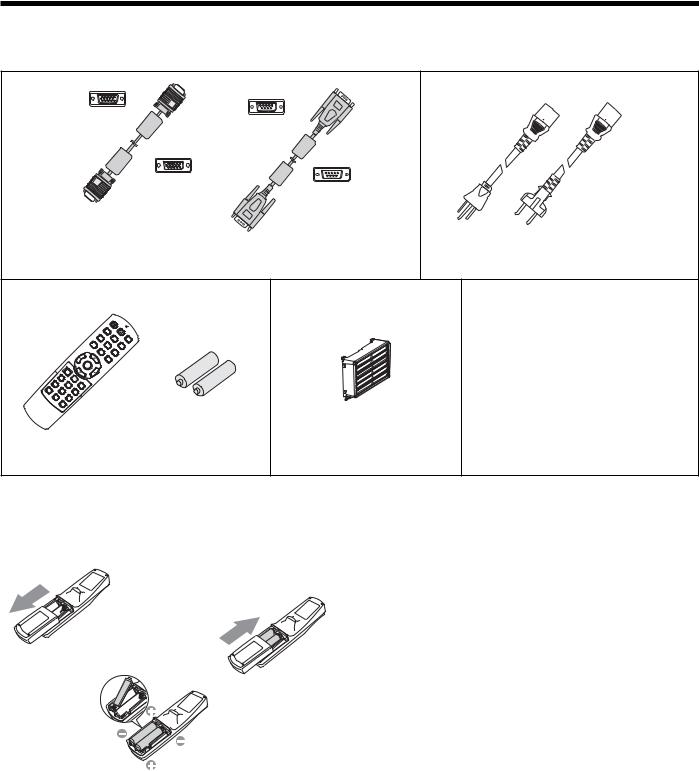
Checking accessories
The following accessories are provided with this projector. Check to be sure that all of the accessories are packed in the package.
Cables
Mini D-SUB
15-pin
Mini D-SUB
15-pin
RGB cable for PC (246C521-10)
D-SUB 9-pin
D-SUB 9-pin
RS-232C cable (246C548-10)
•Used for projector control by computer.
Power supply parts
Power cord (two) (246C483-10, 246C383-20)
Remote control parts |
Filter parts |
Remote control |
R6P (Size-AA) |
Accessory air-filter unit |
(290P158-10) |
battery (two) |
(761B504-10) |
Others
•Lens cap (attached to the projector)
•Lamp replacement tray (857C106-10)
•User Manual/Quick Start up (English only) (871D494-50)
•CD-ROM (with User Manual) (919C154-50)
•Safety Manual/Quick Start up (871D489-50)
Important:
• The attached power cords are to be used exclusively for this product. Never use them for other products.
Inserting the batteries into the remote control
1 |
|
1. |
Remove the back lid of the remote control. |
|
3 |
2. |
Check the polarity (+), (-) of the batteries, and set them |
||
|
||||
|
|
correctly, inserting their (-) side first. |
||
|
|
|
• If the battery is inserted from the (+) side first, inserting |
|
|
|
|
the (-) side is difficult because the coil spring end hits |
|
|
2 |
|
on the battery side. If the battery is forced in this way, |
|
|
|
the outer label of the battery may get ripped and it may |
||
|
|
|
cause a short-circuit and heating. |
|
|
|
3. |
Attach the back lid. |
|
|
|
Important: |
||
|
|
• |
Use two size-AA batteries (R6P). |
|
|
|
• |
Replace the two batteries with new ones when the remote |
|
|
|
|
control is slow to respond. |
|
Caution:
•Use of a battery of wrong type may cause explosion.
•Only Carbon-Zinc or Alkaline-Manganese Dioxide type batteries should be used.
•Dispose of used batteries according to your local regulations.
•Batteries may explode if misused. Do not recharge, disassemble, or throw them in fire.
•Be sure to handle the batteries according to the instructions.
•Load the batteries with its positive (+) and negative (-) sides correctly oriented as indicated on the remote control.
•Keep batteries out of reach of children and pets.
•Remove the batteries, if the remote control is not used for a long time.
•Do not combine a new battery with an old one.
•If the solution of batteries comes in contact with your skin or clothes, rinse with water. If the solution comes in contact with your eyes, rinse them with water and then consult your doctor.
EN-6
Preparing your projector (continued)
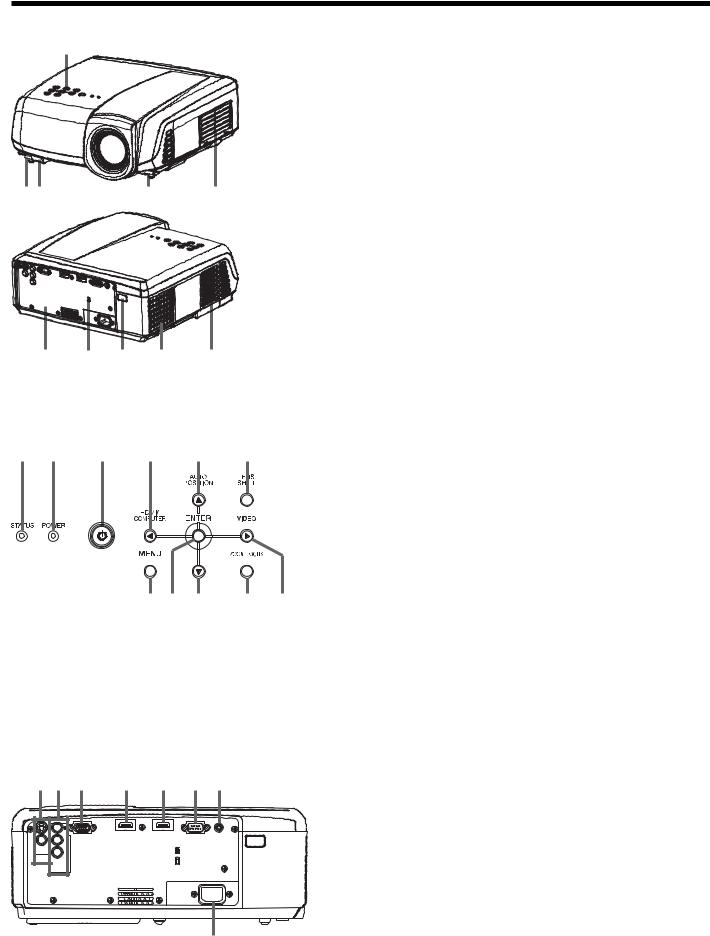
Overview
1
3 2 |
3 |
4 |
5 |
6 |
7 |
8 |
8 |
Control area
1 |
2 |
3 |
4 |
5 |
6 |
7 |
8 |
9 |
10 |
11 |
1 Control area
2 Remote control sensor (Front)
3 Foot adjustment buttons (Left/Right)
4 Air inlet grille
5 Terminal board
6 Kensington Security Lock Standard connector
7 Remote control sensor (Rear)
8 Air outlet grille
1 STATUS indicator
2 POWER indicator
3 POWER button
4 HDMI/COMPUTER/W button
5 AUTO POSITION/S button
6 LENS SHIFT button
7 MENU button
8 ENTER button
9 T button
10 ZOOM/FOCUS button
11 VIDEO/X button
Important:
•While the menu or the screen for password entry is being
displayed, the HDMI/COMPUTER, VIDEO, and AUTO POSITION buttons function as the W, X, and S buttons respectively.
Terminal panel
1 |
2 |
3 |
4 |
5 |
6 |
7 |
|
HDMI IN-1 |
HDMI IN-2 |
|
PB/ |
COMPUTER IN/ |
SERIAL |
TRIGGER |
COMPONENT |
|
|
|
CB |
|
|
|
|
VIDEO IN |
|
|
VIDEO IN |
|
|
|
PR/ |
|
|
|
CR |
|
|
|
S-VIDEO |
|
|
|
IN |
|
|
|
COMPONENT |
|
|
|
VIDEO IN |
|
|
|
AC IN
8
1 VIDEO IN and S-VIDEO IN terminals
2 COMPONENT VIDEO IN terminals
3COMPUTER IN/COMPONENT VIDEO IN terminal (Mini D-SUB 15-pin)
4 HDMI IN-1 terminal (HDMI 19-pin) 5 HDMI IN-2 terminal (HDMI 19-pin)
6SERIAL terminal (D-SUB 9-pin)
•Used for projector control by computer. Contact your dealer for details.
7TRIGGER terminal
• Used for the optional electric screen.
8 Power jack
EN-7
Preparing your projector (continued)
Bottom side
1 |
1 |
|
1 Adjustment feet
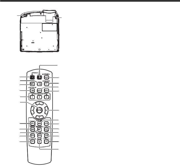
Remote control
|
24 |
|
1 |
23 |
|
2 |
||
22 |
||
3 |
||
21 |
||
4 |
||
20 |
||
5 |
|
|
6 |
|
|
|
19 |
|
7 |
18 |
|
17 |
||
8 |
16 |
|
9 |
15 |
|
10 |
14 |
|
11 |
13 |
|
|
12 |
Important:
1 ON ( I ) button
2 HDMI2 button
3 HDMI1 button
4 COMPONENT button
5 AV MEMORY buttons
6 ENTER button
7 MENU button
8 CONTRAST button*
9 BRIGHTNESS button*
10 GAMMA button*
11 ZOOM/FOCUS button
12 LENS SHIFT button
13 NOISE REDUCTION button*
14 COLOR button*
15 SHARPNESS button*
16 COLOR TEMP. button*
17 ASPECT button
18 AUTO IRIS button
19 Direction buttons
20 VIDEO button
21 S-VIDEO button
22 COMPUTER button
23 AUTO POSITION button
24 OFF ( ) button
* : See below for the picture quality adjusting buttons.
•When you press any button on the remote control, the buttons on the remote control are lit. Wait approx. 6 seconds after releasing the button to turn them off.
•The direction buttons are used for lens shift adjustment. The W and X buttons are also used for zoom/focus adjustment and fine adjustment.
Using the picture quality adjusting buttons
When you press any of the picture quality adjusting buttons, the screen for adjusting the picture quality appears. Adjust the picture quality by pressing the W and X buttons. The picture quality adjustment can be made alternatively in the IMAGE menu. (See page 26.) Items in the menus are shown in parentheses below.
CONTRAST (CONTRAST) ................ |
Adjusts the contrast of the projected image. |
BRIGHTNESS (BRIGHTNESS) ......... |
Adjusts the brightness of the projected image. |
COLOR TEMP. (COLOR TEMP.) ....... |
Selects one of the preset color temperatures. Adjustment of USER mode is also |
|
available. (See page 32.) |
GAMMA (GAMMA MODE)................ |
Selects one of the preset gamma mode. Adjustment of USER mode is also |
|
available. (See page 33.) |
SHARPNESS (SHARPNESS)............ |
Adjusts the sharpness of the projected image. |
COLOR (COLOR).............................. |
Adjusts the color thickness of the projected image. |
NOISE REDUCTION (TRNR, MNR, BAR) ... |
Adjusts the TRNR, MNR and BAR of the projected image. (See page 33.) |
EN-8
Using the remote control
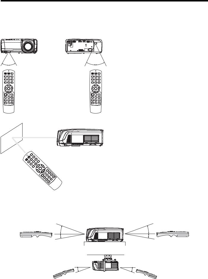
Operational range of the remote control
Front of projector |
Rear of projector |
30° |
|
30° |
30° |
30° |
|
•Keep the remote control photo-sensor out of direct sunlight or fluorescent lamp light.
•Keep the remote control photo-sensor at least 2 m (6 feet) away from fluorescent lamps. Otherwise, the remote control may malfunction.
•If there is an inverter-operated fluorescent lamp near the remote control, the remote control operation may become unstable.
•When you use the remote control too close to the remote control sensor, the remote control may not work correctly.
Operate the remote control within a distance of 10 m (30 feet) from the projector, pointing the
IR beam at the remote control photo-sensor (front or rear) of the projector.
When operating the remote control, keep the distance from the remote control to the projector via the screen within about 5 m (15 feet). The operable range of the remote control, however, depends on the characteristics of the screen.
Reception angle
Vertical directions
20° |
20° |
10° |
10° |
Vertical directions (ceiling mount)
20° |
20° |
EN-9
Setting up your projector
Setting up the screen
Install the screen perpendicularly to the projector. If the screen can not be installed in such a way, adjust the projection angle of the projector. (See page 11.)
•Install the screen and projector so that the projector’s lens is placed at the same height and horizontal position of the screen center.
•Do not install the screen where it is exposed to direct sunlight or lighting. Light directly reflecting on the screen makes the projected images washed-out and hard to view.
SCREEN SIZE
You can keep the image display area within the screen by setting SCREEN SIZE in the ADVANCED MENU of IMAGE menu according to the size of the actual screen.
When setting SCREEN SIZE to CINEMA SCOPE(2.35:1):
•CinemaScope size movies are projected in the full screen.
•Set ASPECT in the FEATURE menu to 16:9 when displaying Vista-size images. In this case, they are squeezed horizontally.
•When ASPECT in the FEATURE menu is set to AUTO and 480i/p, 576i/p, 720p, or 1080i/p signal is input, the part for displaying subtitles is not projected. To display subtitles, reset SCREEN SIZE to 16:9 and adjust the image position using VERTICAL LOCATION in the ADVANCED MENU of the IMAGE menu. (To display the menu on the screen, adjust SHUTTER(U) in the SIGNAL - USER menu to position the menu.)
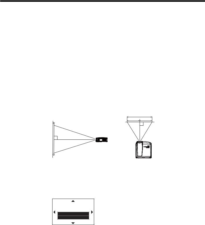
Basic setup
Determine the distance from the screen to the projector according to the size of the images to be projected. (See
page 12.)
W
A B
A=B
Depending on the installation conditions, warm air that is emitted from the exhaust vents may flow into the intake vent, causing the projector to display “TEMPERATURE!!” and then stop projecting images.
LENS SHIFT button
To adjust the positions of the projector and the screen, use LENS SHIFT button.
1.Press the LENS SHIFT button.
• The LENS SHIFT menu appears at the center of the screen.
LENS SHIFT |
FAST |
SELECT : ENTER |
2. Press the S, T, W or X button to move the image position.
•When the T button is pressed, the image moves down.
•When the S button is pressed, the image moves up.
•When the X button is pressed, the image moves to the right.
•When the W button is pressed, the image moves to the left.
•When the ENTER button is pressed while the LENS SHIFT menu is displayed, the shift mode can be switched between FAST and STEP. When FAST is selected, the lens shifts in a large amount with the S, T, W or X button, and it shifts in a small amount when STEP is selected.
•When the LENS SHIFT menu is displayed while no video signal is input to the projector, a crosshatch appears on the entire screen.
•Be careful not to be caught in the opening in the lens while the lens is moving.
•When the lens is vertically shifted by a large amount, color separation may occur.
•While the lens shift is working, the screen may flicker.
EN-10
Setting up your projector (continued)
Adjusting the projection angle
This projector is provided with two feet for adjusting the projection angle on the bottom surface. Adjust the projection angle depending on the position of the projector.
Adjustment of the projection angle
For the best projection, project images on a flat screen installed at 90 degrees to the floor. If necessary, tilt the projector using the two adjustment feet on the bottom of the projector.
Screen
Adjustment feet
1.Tilt up the projector to the appropriate angle.
2.Press the foot adjustment buttons next to the adjustment feet, and the adjustment feet will come out.
3.Release the buttons to lock the adjustment feet to that position.
4.Rotate the adjustment feet for fine adjustment.
After using the projector:
5. Put the adjustment feet back into the projector by pressing the foot adjustment buttons.
• If necessary, rotate the adjustment feet for fine adjustment.
When fine streaks are seen on projected images
This is due to interference with the screen surface and is not a malfunction. Replace the screen or displace the focus a little. (See page 18 or 23 for focus adjustment.)
When projected images are distorted to a trapezoid
When the screen and the projector are not placed perpendicularly to each other, projected images become trapezoidal. If you cannot make the projector and the screen perpendicular to each other by mechanical adjustments, adjust keystone.
With the INSTALLATION menu:
(See page 26 for menu setting.)
1.Display the INSTALLATION menu.
2.Select KEYSTONE by pressing the S or T button.
3.Equalize the widths at the top and bottom of the screen by pressing the W or X button, viewing the screen.
To cancel the menu:
4. Press the MENU button several times.
opt.
|
|
|
|
|
|
|
|
|
|
|
|
|
|
|
|
|
|
|
|
INSTALLATION |
|
|
AV MEMORY 1 |
||||||
|
|
|
|
|
|
|
|
|
|
|
|
KEYSTONE |
|
0 |
|||||
|
|
|
|
|
|
|
|
|
|
Press the W |
Press the X |
button. |
button. |
•The best adjustment result can be obtained when the lens is positioned at the center of the lateral direction at the top in the longitudinal direction. Before performing the keystone adjustment, reset the lens position to the default position by using LENS SHIFT RESET (see page 27) and then move it to the top using LENS SHIFT (see page 10).
•When the keystone adjustment is carried out, the adjustment value is indicated. Note that this value doesn’t mean a projection angle.
•When the keystone adjustment takes effect, the resolution decreases. In addition, stripes may appear or straight lines may bend in images with complicated patterns. They are not due to product malfunctions.
•When the keystone adjustment is carried out, the image may not be displayed correctly because of the type of input signal.
•When the keystone adjustment is performed, the displayed image may be distorted.
•Depending on the installation conditions of the projector and the screen, a perfect rectangular image and the proper aspect ratio may not be obtained.
EN-11
Setting up your projector (continued)
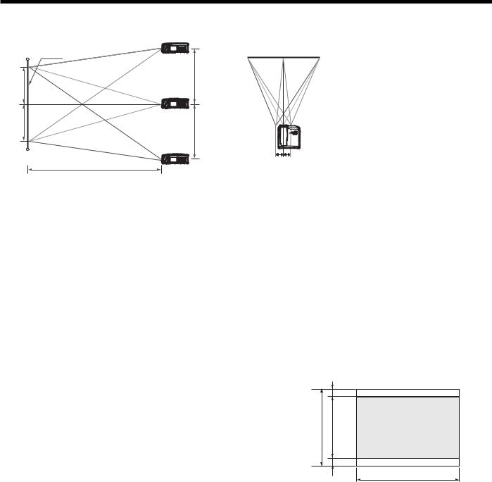
Screen size and projection distance
Refer to the following table to determine the screen size.
Screen height A
Screen width B
SCREEN |
Down side |
|
(H)
50%
50%
|
(H) |
|
Up side |
Left side |
Right side |
|
(L) |
(W) (W) |
|
When the aspect ratio of the screen is 16:9
|
|
Screen size |
|
|
Projection distance (L) |
Lens movable range |
|||||||||
|
|
|
|
|
|
|
|
|
|
|
|
|
|
|
|
Diagonal size |
Height A |
Width B |
Shortest (Wide) |
Longest (Tele) |
|
(H) |
(W) |
|
|||||||
|
|
|
|
|
|
|
|
|
|
|
|
|
|
|
|
inch |
cm |
inch |
cm |
inch |
cm |
inch |
m |
inch |
m |
inch |
|
cm |
inch |
|
cm |
50 |
127 |
25 |
62 |
44 |
111 |
60 |
1.5 |
98 |
2.5 |
18 |
|
47 |
2 |
|
6 |
60 |
152 |
29 |
75 |
52 |
133 |
73 |
1.8 |
118 |
3.0 |
22 |
|
56 |
3 |
|
7 |
70 |
178 |
34 |
87 |
61 |
155 |
85 |
2.2 |
138 |
3.5 |
26 |
|
65 |
3 |
|
8 |
80 |
203 |
39 |
100 |
70 |
177 |
98 |
2.5 |
157 |
4.0 |
29 |
|
75 |
3 |
|
9 |
90 |
229 |
44 |
112 |
78 |
199 |
110 |
2.8 |
177 |
4.5 |
33 |
|
84 |
4 |
|
10 |
100 |
254 |
49 |
125 |
87 |
221 |
123 |
3.1 |
197 |
5.0 |
37 |
|
93 |
4 |
|
11 |
110 |
279 |
54 |
137 |
96 |
244 |
135 |
3.4 |
217 |
5.5 |
40 |
|
103 |
5 |
|
12 |
120 |
305 |
59 |
149 |
105 |
266 |
148 |
3.8 |
237 |
6.0 |
44 |
|
112 |
5 |
|
13 |
150 |
381 |
74 |
187 |
131 |
332 |
185 |
4.7 |
297 |
7.6 |
55 |
|
140 |
7 |
|
17 |
200 |
508 |
98 |
249 |
174 |
443 |
248 |
6.3 |
397 |
10.1 |
74 |
|
187 |
9 |
|
22 |
250 |
635 |
123 |
311 |
218 |
553 |
311 |
7.9 |
497 |
12.6 |
92 |
|
233 |
11 |
|
28 |
300 |
762 |
147 |
374 |
261 |
664 |
373 |
9.5 |
597 |
15.2 |
110 |
|
280 |
13 |
|
33 |
•The above figures are approximate and may be slightly different from the actual measurements.
•Projection distance changes according to the setting of SCREEN SIZE in the ADVANCED MENU in the IMAGE menu. The table above is in the case of “16:9.”
When the aspect ratio of the screen is 4:3
When the aspect ratio of the screen is 4:3, the positional relation between the projected image and the screen is as shown on the right. Refer to the following table for installation.
|
D |
C |
A |
|
D |
|
B |
When the aspect ratio of the image is 16:9
|
|
Screen size |
|
|
Size of the projected image |
Black |
Projection distance (L) |
Lens movable range |
|||||||||||||
Diagonal size |
Height C |
Width B |
Height A |
Width B |
space (D) |
Shortest (Wide) |
Longest (Tele) |
|
(H) |
(W) |
|
||||||||||
|
|
|
|
|
|
|
|
|
|
|
|
|
|
|
|
|
|
|
|
|
|
inch |
cm |
inch |
cm |
inch |
cm |
inch |
cm |
inch |
cm |
inch |
cm |
inch |
m |
inch |
m |
inch |
|
cm |
inch |
|
cm |
50 |
127 |
30 |
76 |
40 |
102 |
23 |
57 |
40 |
102 |
4 |
10 |
55 |
1.4 |
89 |
2.3 |
17 |
|
43 |
2 |
|
5 |
60 |
152 |
36 |
91 |
48 |
122 |
27 |
69 |
48 |
122 |
5 |
11 |
66 |
1.7 |
108 |
2.7 |
20 |
|
51 |
2 |
|
6 |
70 |
178 |
42 |
107 |
56 |
142 |
32 |
80 |
56 |
142 |
5 |
13 |
78 |
2.0 |
126 |
3.2 |
24 |
|
60 |
3 |
|
7 |
80 |
203 |
48 |
122 |
64 |
163 |
36 |
91 |
64 |
163 |
6 |
15 |
89 |
2.3 |
144 |
3.7 |
27 |
|
69 |
3 |
|
8 |
90 |
229 |
54 |
137 |
72 |
183 |
41 |
103 |
72 |
183 |
7 |
17 |
101 |
2.6 |
163 |
4.1 |
30 |
|
77 |
4 |
|
9 |
100 |
254 |
60 |
152 |
80 |
203 |
45 |
114 |
80 |
203 |
8 |
19 |
112 |
2.9 |
181 |
4.6 |
34 |
|
86 |
4 |
|
10 |
110 |
279 |
66 |
168 |
88 |
224 |
50 |
126 |
88 |
224 |
8 |
21 |
124 |
3.1 |
199 |
5.1 |
37 |
|
94 |
4 |
|
11 |
120 |
305 |
72 |
183 |
96 |
244 |
54 |
137 |
96 |
244 |
9 |
23 |
135 |
3.4 |
218 |
5.5 |
41 |
|
103 |
5 |
|
12 |
150 |
381 |
90 |
229 |
120 |
305 |
68 |
171 |
120 |
305 |
11 |
29 |
170 |
4.3 |
273 |
6.9 |
51 |
|
129 |
6 |
|
15 |
200 |
508 |
120 |
305 |
160 |
406 |
90 |
229 |
160 |
406 |
15 |
38 |
227 |
5.8 |
365 |
9.3 |
68 |
|
171 |
8 |
|
20 |
250 |
635 |
150 |
381 |
200 |
508 |
113 |
286 |
200 |
508 |
19 |
48 |
285 |
7.2 |
456 |
11.6 |
84 |
|
214 |
10 |
|
25 |
300 |
762 |
180 |
457 |
240 |
610 |
135 |
343 |
240 |
610 |
23 |
57 |
342 |
8.7 |
548 |
13.9 |
101 |
|
257 |
12 |
|
30 |
•The above figures are approximate and may be slightly different from the actual measurements.
•Projection distance changes according to the setting of SCREEN SIZE in the ADVANCED MENU in the IMAGE menu. The table above is in the case of “16:9.”
EN-12
Setting up your projector (continued)
Front projection, ceiling mounting
For ceiling mounting,
you need the ceiling mount kit designed
for this projector. Ask a specialist for
installation. For details, consult your dealer.
•The warranty on this projector does not cover any damage caused by use of any non-recommended ceiling mount kit or installation of the ceiling mount kit in an improper location.
•When using the projector mounted on the ceiling, set IMAGE REVERSE in the INSTALLATION menu to MIRROR INVERT. See page 27.
•When the projector is mounted on the ceiling, images may appear darker than those projected in the case of tabletop mounting. This isn’t a product malfunction.
•Ask your installation specialist to provide an A/C power switch. When you do not use the projector, be sure to shut down the main power by the switch.
•Do not install the projector where the exhaust vents are exposed to air emitted by an air conditioning. Such installation may cause a breakdown.
•Do not install the projector near a fire alarm because it emits hot air from its exhaust vents.
Rear projection
Ask a specialist for installation. For details, consult your dealer.
• For rear projection, set IMAGE
REVERSE in the
INSTALLATION menu to MIRROR. See page 27.
Caution:
•Placing the projector directly on a carpet impairs ventilation by the fans, causing damage or failure. Put a hard board under the projector to facilitate ventilation.
•Place the projector at least 50 cm (or 20 inch) away from the wall to prevent the air inlet grille and the air outlet grilles that emit hot air from being blocked.
•Do not use the projector in the following locations and manners, which may cause fire or electric shock.
•In a dusty or humid place.
•In a sideways position, or with the lens facing down.
•Near a heater.
•In an oily, smoky, or damp place such as a kitchen.
•In direct sunlight.
•Where the temperature rises high, such as in a closed car.
•Where the temperature is lower than +41ºF (or +5ºC) or higher than +95ºF (or +35ºC ).
Important:
•We don’t recommend using the projector at an altitude of 1500 meters or higher. Use at an altitude of 1500 meters or higher may affect the projector’s life.
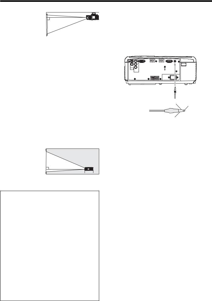
TRIGGER terminal
The TRIGGER terminal on the rear of the projector is a terminal that outputs a 12 V signal to control an externally connected device (electric screen) when images are projected.
|
HDMI IN-1 |
HDMI IN-2 |
TRIGGER |
PB/ |
COMPUTER IN/ |
SERIAL |
|
COMPONENT |
|
|
|
CB |
|
|
|
|
VIDEO IN |
|
|
VIDEO IN |
|
|
|
PR/ |
|
|
|
CR |
|
|
|
S-VIDEO |
|
|
|
IN |
|
|
|
COMPONENT |
|
|
|
VIDEO IN |
|
|
|
AC IN
TRIGGER
To externally connected device
Ring (NC) |
Tip (12 V) |
|||||||
|
|
|
|
|
|
|
|
|
|
|
|
|
|
|
|
|
|
|
|
|
|
|
|
|
|
|
(Ground 0 V)
To use the TRIGGER terminal, set TRIGGER OUT to ON in the INSTALLATION menu. (The factory default is OFF.) Use the following steps to change the setting.
With the INSTALLATION menu:
(See page 26 for menu setting.)
1.Display the INSTALLATION menu.
2.Select TRIGGER OUT by pressing the S or T button.
3.Select ON by pressing the W or X button.
To cancel the menu:
4. Press the MENU button.
Caution:
•Do not use the signal output from the TRIGGER terminal as a power for other devices.
•Do not link the TRIGGER terminal with an audio terminal of other device because that device may be damaged.
•The rated current for the TRIGGER terminal is 200 mA. If you use a current exceeding this rating, a failure may occur.
•For information about electric screens, please contact screen manufacturers.
EN-13

Viewing video images
A. Connecting the projector to video equipment
•When the projector and the connected devices are located too close to each other, the projected image may be affected by their interference.
•See the owner’s guide of each device for details about its connections.
Preparation:
• Make sure that the power of the projector and that of the video equipment are turned off.
Basic home theater system connection
|
HDMI IN-1 |
HDMI IN-2 |
|
|
COMPUTER IN/ |
SERIAL |
TRIGGER |
PB/ COMPONENT |
|
|
|
CB |
VIDEO IN |
|
|
|
|
|
|
VIDEO IN |
|
|
|
PR/ |
|
|
|
CR |
|
|
|
S-VIDEO |
|
|
|
IN |
|
|
|
COMPONENT |
|
|
|
VIDEO IN |
|
|
|
AC IN
Video player
DVD player
Set-top box or digital tuner
EN-14
Viewing video images (continued)
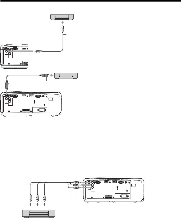
Connecting to a video player, etc.
Video player, or the like
2
To video output terminal
|
|
1 |
To VIDEO |
|
|
|
IN terminal |
|
HDMI IN-1 |
HDMIHDMIIN IN-2 |
|
PB/ |
COMPUTER IN/ |
SERIAL TRIGGER |
|
COMPONENT |
|
|
|
CB |
|
|
|
|
VIDEO IN |
|
|
VIDEO IN |
|
Video cable (option) |
|
IN |
|
||
PR/
CR
S-VIDEO
COMPONENT
VIDEO IN
AC IN
1.Connect one end of the optional video cable to the VIDEO IN terminal of the projector.
2.Connect the other end of the video cable to the video output terminal of the video equipment.
Video player, or the like
S-video cable (option)
|
To S-VIDEO |
2 |
To S-video |
|
|
output terminal |
|
|
1 IN terminal |
|
|
|
HDMI IN-1 |
HDMI IN-2 |
|
PB/ |
COMPUTER IN/ |
SERIAL TRIGGER |
|
COMPONENT |
|
|
|
CB |
|
|
|
|
VIDEO IN |
|
|
VIDEO IN |
|
|
|
PR/ |
|
|
|
CR |
|
|
|
S-VIDEO |
|
|
|
IN |
|
|
|
COMPONENT |
|
|
|
VIDEO IN |
|
|
|
AC IN
When the video equipment is equipped with the S-video output terminal, make the connection as follows:
1.Connect one end of the optional S-video cable to the S-VIDEO IN terminal of the projector.
2.Connect the other end of the S-video cable to the S-video output terminal of the video equipment.
•Also read the instruction manual of the equipment to be connected.
•Contact your dealer for details of connection.
When a TV tuner or VCR is connected:
When you use this projector with a TV tuner or VCR connected, no image may appear or a message of NO SIGNAL may appear on the screen when you change the channel via any channel that is not being received. In such a case, set the channels of the TV tuner or VCR again. To avoid such symptom, use the TV tuner or VCR with its channel skip function (that is a function not to display channels that are not being received) enabled.
Connecting to a DVD player or HDTV decoder
To connect this projector to video equipment that has component video output terminals, such as a DVD player, use the COMPONENT VIDEO IN terminals.
Y
Component cable (option)
Y |
|
HDMI IN-1 |
HDMI IN-2 |
|
PB/ |
COMPUTER IN/ |
|
SERIAL |
TRIGGER |
COMPONENT |
|
|
|
|
CB |
|
|
|
|
|
VIDEO IN |
|
|
|
VIDEO IN |
|
|
|
|
PR/ |
|
|
|
|
CR |
|
|
|
|
S-VIDEO |
|
|
|
|
IN |
|
|
|
|
COMPONENT |
|
|
|
|
VIDEO IN |
|
|
|
|
PR/CR |
|
|
AC IN |
|
PB/CB
PR/CR PB/CB Y
DVD player or HDTV decoder
•The terminal’s names Y, PB, and PR are given as examples of when a HDTV decoder is connected.
•The terminal’s names vary depending on the connected devices.
•Images may not be projected correctly depending on the type of the DVD player you use.
•Though it may take some time before an image is displayed on the screen depending on the type of the input signal, such symptom is not a malfunction.
•When connecting a HDTV decoder having RGB output terminals, set COMPUTER INPUT to RGB in the SIGNAL menu.
EN-15
 Loading...