


Mitsubishi Electric Air-conditioner Network System
Central Controller
Model: G-50A
Instruction Book
 ON/OFF
CENTRAL CONTROLLER G-50A
Contents
1.Safety …………………………………………… 1
2.Product feature ………………………………… 2
3.Function ………………………………………… 4 3-1 Specification …………………………… 4
4. |
3-2 Display screen ………………………… 8 |
|||
User operation ………………………………… 10 |
||||
|
4-1 Operation condition monitor |
…………… 11 |
||
|
4-2 Operation setting ……………………… 12 |
|||
|
4-2-1 |
Group operation setting |
………… 12 |
|
|
4-2-2 |
Collective operation setting ……… 16 |
||
|
4-3 Timer operation ………………………… 19 |
|||
|
4-4 Malfunction ……………………………… 23 |
|||
5. |
4-5 Current time setting …………………… 24 |
|||
Initial setting |
…………………………………… 25 |
|||
|
5-1 Shifting to initial setting menu |
………… 25 |
||
|
5-2 M-NET address setting |
………………… 25 |
||
|
5-3 Function setting ………………………… 26 |
|||
|
5-4 Group configuration setting |
…………… 27 |
||
|
5-5 Interlocked operation setting |
………… 29 |
||
|
5-6 Group name setting …………………… 31 |
|||
|
5-7 User setting …………………………… 34 |
|||
|
5-8 IP address setting ……………………… 35 |
|||
6. |
5-9 Initial setting tools connection function |
………… 35 |
||
Maintenance …………………………………… 36 |
||||
|
6-1 Refrigerant system monitor |
…………… 36 |
||
7. |
6-2 Malfunction log monitor |
……………… 37 |
||
External input / output ………………………… 38 |
||||
|
7-1 External input function |
………………… 38 |
||
|
7-2 External output function ………………… 39 |
|||
Appendix 1 : Initial setting(adridged) ………………… 40 Appendix 2 : User operation(adridged) ………………… 42
Before using the controller, please read this Instruction Book carefully to ensure correct operation. Store this Instruction Book in a location that is easy to find.
1 . SAFETY
Please take a moment to review these safety precautions. They are provided for your protection and to prevent damage to the controller.
This safety information applies to all operators and service personnal.
After you have read this manual, always observe the procedures described in the explanations and store it with the installation manual in a location that is easy to find. If the controller is going to be operated by another person, make sure that this manual is given to them.
Symbols and Terms
 WARNING Statements identify condition or practices that could result in personal injury or loss of life.
 CAUTION Statements identify condition or practices that could result in damage to the controller or other property.
Specific Precautions
 WARNING
•Ask your dealer or technical representative to install.
If incorrect inatallation is done by a customer, it may cause an electric shock, fire, etc.
•Securely install in a place which can withstand the weight of the controller.
If it is not enough, the controller may fall and cause an injury.
•Make sure that the controller is connected to a rated power supply.
If the controller is not connected to a rated power supply, it may cause a fire or damage to the controller.
•Never remove the cover during operation.
Touching the charged parts of the controller may cause severe burns or other personal injury.
•Stop the operation if any malfunction occurs.
If malfunction occurs (burning smell, etc.) stop the operation and turn off the power supply. Contact your dealer or technical representative immediately. If the controller continues to operate after a malfunction occurs, this may cause damage, electric shock or fire.
•Do not move and re-install the controller by yourself.
If installation is incorrect, it may cause an electric shock, fire,etc. Ask your dealer or technical representative.
•Contact your dealer if the controller will not be used any more or will be scrapped.
•Do not remodel or repair by yourself.
If the controller is redesigned or repair is not correct, it may cause an electric shock, fire, etc.
Consult your dealer if repair is necessary.
•Stop the operation immediately and notify the your dealer if an error code is displayed or malfunction occurs.
Fire or damage may be caused if the controller is operated in this condition .
 CAUTION
•Do not install the controller in a place where inflammable gas could leak.
If gas leaks and collects around the controller, it may cause a fire or explosion.
•Do not wash the controller with water.
It may cause an electric shock or malfunction.
•Do not touch the switch with wet hands.
It may cause an electric shock.
•Do not use the controller for special applications.
This product is designed for use with the MITSUBISHI ELECTRIC BUILDING AIR CONDITIONING CONTROL SYSTEM. Do not use the system for other air condition management operation or applications. It may cause malfunctions.
•Do not apply insecticide or flammable sprays to the controller.
Do not place flammable spray near the controller and make sure it does not blow directly on the controller as this may cause in fire.
•Do not use the controller in special environments.
The performance may be reduce or parts may be damaged if the controller is used in locations subject to large quantities of oil (including machine oil), steam, sulfide gas.
•Do not touch the switches with sharp objects.
It may cause an electric shock or malfunction.
•Operate the controller within the specified temperature range.
Observe the specified temperature range when operating the controller. If the controller is used outside the specified temperature range, it may cause serious damage. Be sure to check the operation temperature range in the operation manual.
-1-
2 . Product Features
The central controller is capable of controlling up to 50 air conditioner units. It supports the following operating function.
[ 1 ] User operating function
(1)Operation
1.Virtually almost functions operated by local remote controller are supported.
The central controller can be used to control the indoor units in specific group ON or OFF, select the operating mode (COOL, DRY, FAN, AUTO and HEAT) for the indoor unit or HEAT RECOVERY, BY-PASS, AUTO for the ventilation unit), select the fan speed, select the air direction (4 direction and swing operation), select the ventilation mode (OFF, LOW speed, or HIGH speed), select TIMER MODE and select the temperature setting.
In addition, room temperature can be displayed at the unit of each group upon request. (See 5-5 "User setting")
2. Local remote control operation can be prohibited for specific functions.
Access to specific control functions, such as ON/OFF operation, mode selection ,temperature setting and filter sign reset operation can be prohibited for the local remote controls collectively or per group.
3. Collectively setting
Operation setting can be performs collectively or per group.
(2)Weekly Schedule
1.The weekly schedule enables four different schedule patterns to be set weekly per group. (P1-P4)
Of these, three patterns are to set ON/OFF schedule and remaining one pattern is to set the pattern to prohibit operation of the local remote controller.
Four patterns (daily patterns) mentioned above enable the setting of individual schedule times for every group.
2.The respective daily patterns enable the setting of three different ON times (three prohibition times) and three different OFF times (three permission times).
In addition, it is possible to set ON time only (prohibition time only) and OFF time only (permission time only).
3.Easy setting
Daily operation patterns and weekly schedules for one group can easily be copied to the other groups.
4.Timer automatic recovery operation when recovering from a power down is supported.
(3)Operating status monitor
1.ON/OFF/MALFUNCTION status can be monitored by group or by unit.
2.The groups managed by the central controller may be displayed all together by group number or group name (first three characters). Collective display of all unit address is also supported.
3.When displaying all groups at once, individual groups can be turned ON or OFF by designating them by the
 indicator .
(4)Malfunction monitor
1.The unit address where the malfunction occurred, the error code and address of the unit that detected the malfunction are displayed on the malfunction monitor screen.
2.Pressing the reset key stops all the units connected to the same group, refrigerant system or linked group to the unit where the malfunction occurred, all of these are reset.
-2-
[ 2 ] System configuration setup and maintenance function
(1)Setup for system configuration
1.Registration can be made for the indoor units, local remote controllers and slave system controllers in the same group.
And also registration can be made for the ventilation such as OA processing unit.
2.Group name may be specified. ( Names may include alphanumeric characters.)
3.Group name may be copied.
4.Setting of group configuration and specifying the group name may be performed as long as power is being supplied to the central controller. This mean that setting can be performed before the central controller is installed at
the site, before installation of individual units is completed or while the power supply to some units is cut off.
5.System configuration data setting in the central controller can be deleted at once if necessary when replacing circuits wired board, etc.
(2)Refrigerant system monitor
All unit address (indoor, outdoor, etc.) can be displayed for individual refrigerant system on the refrigerant system monitor screen. This information is useful for checking the installation, such as address setting, transmission line connection and power supply connection.
(3) Interlocked group setting
Setting can be performed for indoor units interlocked with a ventilation unit.
If even one of the indoor units interlocked with ventilation have started to operate, the ventilation will be activated.
(4)Malfunction log monitor
1.A log of the last 64 malfunction massage, in the order in which they occurred, can be monitored.
2.The data and time the malfunction occurred, the address of unit where it occurred, the error code and the address of unit that detected the malfunction are displayed.
3.All malfunction logged in the memory of the central controller and indoor unit can be reset at once.
[ 3 ] Other
(1) Overall statues display lamp
Displays normal operation/all OFF/malfunction status for the entire system.
(Normal operation/all OFF/malfunction status is indicated by the lamp being lit, not lit or blinking respectively)
(2) Collective ON/OFF switch
This switch allows turning all of the unit in the system ON or OFF at once.
(3) Power supply wiring
The central controller is supplied power from the PAC-SC50KUA Power Supply Unit via the M-NET transmission line and DC power line. The DC power between the PAC-SC50KUA Power Supply Unit and the central controller should be 10m or less. The central controller allows to be connected to M-NET transmission line at any position. (M-NET transmission line is the central control line which connects TB7 terminal of the outdoor unit)
(4) M-NET transmission line
The combined maximum distance between the outdoor units and the central controller, and between the outdoor units and farthest indoor units connected to the same refrigerant system or their remote controller, may be extended up 500 meters.
Therefore, even if the total distance is made longer by installing the outdoor units all in row, there will be no problem so long as the above maximum total distance limitation is not exceeded.
-3-
3 . Functions
3-1 Specifications
Item
Source power requirement
Environmental condition
Dimensions
Weight
System condition
Number of control unit *3
User operating function ON/OFF
Operation mode *1
Fan speed *1
Operation
Air direction and swing operation *1
Temperature setting
|
|
|
Specification |
|
||
|
|
DC24V,0.02A(Maximum loading) |
|
|||
Input voltage |
Power received from PAC-SC50KUA Power Supply Unit via M-NET transmission line. |
|||||
DC12V,0.2A(Maximum loading) |
|
|||||
|
|
|
||||
|
|
Power is received from the PAC-SC50KUA Power Supply Unit via the DC power line. |
||||
Temperature |
Operating |
0 ˚C |
+40 ˚C / 32 ˚F |
+104 ˚F |
||
Non operating |
-20 ˚C |
+60 ˚C / – 4 ˚F |
+140 ˚F |
|||
|
|
|||||
Humidity |
30 90%RH (No condensation) |
|
||||
mm |
120(H) |
300(W) 80[*19](D) |
*[ ] : indicate the thickness from the |
|||
in |
4-3/4(H) 11-13/16(W) |
3-1/8[*3/4](D) wall. |
|
|||
Kg |
1.0 |
|
|
|
|
|
lb |
2-1/4 |
|
|
|
|
|
Indoor unit or independent OA processing unit or LOSSNAY : 50 units maximum (50 groups maximum)
Number of units (indoor or independent OA processing unit or LOSSNAY) in one group : 1-16 units
*Note Indoor unit, independent OA processing unit and LOSSNAY can not register to the same group.
Number of remote controllers in one group : 1-2
Number of system controllers in one group
:0-4 (including the number of remote controller in one group)
:0-3 for groups which have one remote controller.
Number of indoor units interlocked with one OA processing unit or LOSSNAY
: 0-16 (some types of OA processing unit can only be operated when interlocked to a maximum of 9 units)
The ON/OFF operation can be performed as a collective or per group.
The switch operation for the operation mode setting can be performed as a collective or per group.
[ Selectable operation mode for the indoor unit ] Cool/Dry/Fan/Auto/Heat
[ Selectable operation mode for the independent ventilation ] Heat recovery/By-pass/Auto
The switch operation to set the High and Low speed can be performed as a collective or per group.
( The 4 fan speed setting is available to the indoor that has 4 levels )
The air flow direction can be switched to 4 directions and swing operation as a collective or per group
Temperature setting can be performed collectively or per group.
[Setting temperature range] |
|
|
|
Cool (Dry) operation |
: 19 |
30 ˚C / 67 |
87 ˚F |
Heat operation |
: 17 |
28 ˚C / 63 |
83 ˚F |
Auto operation |
: 19 |
28 ˚C / 67 |
83 ˚F |
-4-
|
Item |
|
|
|
|
|
|
|
|
|
|
|
|
|
|
|
|
|
Specification |
||||||||||
|
|
|
|
|
|||||||||||||||||||||||||
|
|
|
|
The specific functions of a local remote controller can be prohibited as a collective or |
|||||||||||||||||||||||||
|
|
Prohibit local |
per group. |
||||||||||||||||||||||||||
|
|
remote |
|
|
[Prohibit function] |
||||||||||||||||||||||||
|
|
control |
|
|
|
ON/OFF operation, Operation mode setting, Temperature setting and Filter sign |
|||||||||||||||||||||||
|
|
|
|
|
|
reset operation. |
|||||||||||||||||||||||
|
|
|
|
|
|||||||||||||||||||||||||
|
|
Timer operation |
The set schedule operations can be switched to ON/OFF (local remote controller |
||||||||||||||||||||||||||
Operation |
|
operation prohibition/permission) for each group. |
|||||||||||||||||||||||||||
|
|
|
|||||||||||||||||||||||||||
|
|
Filter sign |
|
The filter sign reset operation after the air filters are cleaned can be performed as a |
|||||||||||||||||||||||||
|
|
reset |
|
collective or per group. |
|||||||||||||||||||||||||
|
|
|
|
The ventilation operation of the interlocked OA processing unit or LOSSNAY can be coll- |
|||||||||||||||||||||||||
|
|
Ventilation |
|
ective or per group. |
|||||||||||||||||||||||||
|
|
operation |
*1 |
|
[Ventilation operation] |
||||||||||||||||||||||||
|
|
|
*3 |
|
|
|
|
Low speed/High speed/Ventilation OFF |
|||||||||||||||||||||
|
|
|
|
|
|
|
|
|
|
|
|
|
|
|
|
|
|
|
|
|
|
|
|
|
|
|
|
|
|
|
|
Collective |
|
The overall status lamp displays conditions of the collective statues. |
|||||||||||||||||||||||||
|
|
operation |
|
||||||||||||||||||||||||||
|
|
|
|
|
|
|
|
|
|
|
|
|
|
|
|
|
|
|
|
|
|
|
|
|
|
|
|
|
|
|
|
|
|
|
|||||||||||||||||||||||||
|
|
Each group |
|
Each group operation is displayed on the operation setting screen (group) or operation |
|||||||||||||||||||||||||
|
|
operation |
|
monitor screen. |
|||||||||||||||||||||||||
|
|
Operation |
|
|
|
|
|
|
|
|
|
|
|
|
|
|
|
|
|
|
|
|
|
|
|
|
|
|
|
|
|
mode |
|
|
|
|
|
|
|
|
|
|
|
|
|
|
|
|
|
|
|
|
|
|
|
|
|
|
|
|
|
|
|
|
|
|
|
|
|
|
|
|
|
|
|
|
|
|
|
|
|
|
|
|
|
|
|
|
|
|
|
Fan speed |
|
|
|
|
|
|
|
|
|
|
|
|
|
|
|
|
|
|
|
|
|
|
|
|
|
|
|
|
|
|
|
|
|
|
|
|
|
|
|
|
|
|
|
|
|
|
|
|
|
|
|
|
|
|
|
|
|
|
|
Air direction |
|
|
|
|
|
|
|
|
|
|
|
|
|
|
|
|
|
|
|
|
|
|
|
|
|
|
|
|
|
|
|
|
|
|
|
|
|
|
|
|
|
|
|
|
|
|
|
|
|
|
|
|
|
|
|
|
|
|
|
Temperature |
|
|
|
|
|
|
|
|
|
|
|
|
|
|
|
|
|
|
|
|
|
|
|
|
|
|
|
|
|
setting |
|
|
|
|
|
|
|
|
|
|
|
|
|
|
|
|
|
|
|
|
|
|
|
|
|
|
|
|
|
|
|
|
|
|
|
|
|
|
|
|
|
|
|
|
|
|
|
|
|
|
|
|
|
|
|
|
|
|
|
Timer |
|
|
|
|
|
|
|
|
|
|
|
|
|
|
|
|
|
|
|
|
|
|
|
|
|
|
|
|
|
operation |
|
|
|
|
|
|
|
|
|
|
|
|
|
|
|
|
|
|
|
|
|
|
|
|
|
|
|
|
|
Filter sign |
|
|
|
|
|
|
|
|
|
|
|
|
|
|
|
|
|
|
|
|
|
|
|
|
|
|
|
Monitor |
|
Local remote |
|
|
|
|
|
|
|
|
|
|
|
|
|
|
|
|
|
|
|
|
|
|
|
|
|
|
|
|
control |
|
|
|
|
|
|
|
|
|
|
|
|
|
|
|
|
|
|
|
|
|
|
|
|
|
|
|
|
|
|
|
Displayed on the operation setting screen (group). |
||||||||||||||||||||||||||
|
|
prohibition |
|
||||||||||||||||||||||||||
|
|
|
|
|
|
|
|
|
|
|
|
|
|
|
|
|
|
|
|
|
|
|
|
|
|
|
|
|
|
|
|
|
|
|
|
|
|
|
|
|
|
|
|
|
|
|
|
|
|
|
|
|
|
|
|
|
|
|
|
|
|
Ventilation |
|
|
|
|
|
|
|
|
|
|
|
|
|
|
|
|
|
|
|
|
|
|
|
|
|
|
|
|
|
operation |
*3 |
|
|
|
|
|
|
|
|
|
|
|
|
|
|
|
|
|
|
|
|
|
|
|
|
|
|
|
|
|
|
|
|
|
|
|
|
|
|
|
|
|
|
|
|
|
|
|
|
|
|
|
|
|
|
|
|
|
|
Room |
|
|
|
|
|
|
|
|
|
|
|
|
|
|
|
|
|
|
|
|
|
|
|
|
|
|
|
|
|
temperature |
|
|
|
|
|
|
|
|
|
|
|
|
|
|
|
|
|
|
|
|
|
|
|
|
|
|
|
|
|
display |
|
|
|
|
|
|
|
|
|
|
|
|
|
|
|
|
|
|
|
|
|
|
|
|
|
|
|
|
|
|
|
|
|
|
|
|
|
|
|
|
|
|
|
|
|
|
|
|
|
|
|
|
|
|
|
|
|
|
|
Central control |
|
|
|
|
|
|
|
|
|
|
|
|
|
|
|
|
|
|
|
|
|
|
|
|
|
|
|
|
|
prohibition |
|
|
|
|
|
|
|
|
|
|
|
|
|
|
|
|
|
|
|
|
|
|
|
|
|
|
|
|
|
|
|
|
|
|
|
|
|
|
|
|
|
|
|
|
|
|
|
|
|
|
|
|
|
|
|
|
|
|
|
External |
|
|
|
|
|
|
|
|
|
|
|
|
|
|
|
|
|
|
|
|
|
|
|
|
|
|
|
|
|
input signal |
|
|
|
|
|
|
|
|
|
|
|
|
|
|
|
|
|
|
|
|
|
|
|
|
|
|
|
|
|
condition |
|
|
|
|
|
|
|
|
|
|
|
|
|
|
|
|
|
|
|
|
|
|
|
|
|
|
|
|
|
|
|
|
|||||||||||||||||||||||||
|
|
Malfunction |
|
The unit address and error code are displayed on the malfunction monitor screen when |
|||||||||||||||||||||||||
|
|
|
a malfunction occurs. |
||||||||||||||||||||||||||
|
|
|
|
||||||||||||||||||||||||||
|
|
|
|
|
|||||||||||||||||||||||||
|
|
Current time |
When the power is cut off, the current time is backed up for approximately one week. |
||||||||||||||||||||||||||
|
|
(When the controller is fully charged. The controller is fully charged by twenty-four |
|||||||||||||||||||||||||||
|
|
back-up |
|
||||||||||||||||||||||||||
|
|
|
hours after power feed.) |
||||||||||||||||||||||||||
|
|
|
|
||||||||||||||||||||||||||
|
|
|
|
|
|||||||||||||||||||||||||
|
|
|
|
Operation pattern setting can be performed. |
|||||||||||||||||||||||||
|
|
|
|
• Operation interval : Minimum 10 minutes |
|||||||||||||||||||||||||
|
|
|
|
• The daily operation pattern and weekly schedule for each group can be set. |
|||||||||||||||||||||||||
|
|
|
|
• A pattern of one day : P1/P2/P3/ |
|
|
/ |
|
|
/ |
|
/ |
|
/ - |
|||||||||||||||
|
|
|
|
P1 |
P2 |
P3 |
P4 |
||||||||||||||||||||||
Other |
|
|
|
* ON/OFF setting up to three times a day are possible for P1/P2/P3. |
|||||||||||||||||||||||||
|
|
Timer setting |
* |
P4 |
enables to set operation prohibition of 3 times per day for the remote controller. |
||||||||||||||||||||||||
|
|
* |
|
|
/ |
|
|
/ |
|
implement the schedule which has combined P1/P2/P3 of ON/OFF |
|||||||||||||||||||
|
|
|
|
P1 |
P2 |
P3 |
|||||||||||||||||||||||
|
|
|
|
|
pattern and |
|
of remote controller operation prohibition pattern together. |
||||||||||||||||||||||
|
|
|
|
|
P4 |
||||||||||||||||||||||||
|
|
|
|
|
( |
|
|
= P1 + |
|
/ |
|
= P2 + |
|
/ |
|
= P3 + |
|
|
|
is displayed.) |
|||||||||
|
|
|
|
|
P1 |
P4 |
P2 |
P4 |
P3 |
P4 |
|||||||||||||||||||
|
|
|
|
* - is a day without timer operation. |
|||||||||||||||||||||||||
|
|
|
|
• "The reference temperature and set-back value" or "Setting temperature" which are |
|||||||||||||||||||||||||
|
|
|
|
linked with timer operation can be set. |
|||||||||||||||||||||||||
|
|
|
|
|
|
|
|
|
|
|
|
|
|
|
|
|
|
|
|
|
|
|
|
|
|
|
|
|
|
-5-
|
Item |
|
Specification |
|
|
|
|
|
|
|
|
Group |
name |
Group name can be specified and display on the operation setting screen. |
|
|
designation |
* Group name setting is need at the initial setting. |
|
|
|
|
|
|
|
|
External |
Emergency stop/normal, ON/OFF, prohibit/permit for local remote operation can be |
|
Other |
|
signal input |
controlled for units being controlled with a non-voltage contact signal input from an |
|
|
interface |
external source. |
||
|
|
|||
|
|
External |
When one or more units being controlled are operating, the "ON" signal will be out- |
|
|
|
signal output |
put, and if a malfunction occurs in one or more units, the "malfunction" signal will |
|
|
|
interface |
be output. |
|
|
|
|
||
Initial setting (for installation and maintenance) |
||||
|
|
Group setting |
The group setting operation for units (indoor units local remote controllers, independ- |
|
Connecting |
|
ent OA processing unit, LOSSNAY and slave system controllers) are performed on |
||
|
|
*3 |
the group setting screen. |
|
information |
|
|
||
setting |
|
Interlocked |
The interlocked setting for the ventilation equipment as the OA processing unit or |
|
|
|
setting |
*3 |
LOSSNAY , etc to indoor unit is performed on the interlocked setting screen. |
|
|
|
|
|
|
|
Malfunction |
A maximum of the 64 most recent malfunction are displayed on the malfunction log |
|
Monitor |
|
history |
|
monitor. |
|
Refrigerant |
The connected unit address are displayed on the refrigerant monitor screen. |
||
|
|
|||
|
|
system monitor |
||
|
|
|
|
|
|
|
User setting |
Some of the indication and function that appear on the each screen can be specified to |
|
|
|
match the needs of the user. |
||
|
|
|
|
|
|
|
|
|
|
|
|
Master system |
|
|
|
|
controller/ |
|
|
|
|
Slave system |
Master/Slave setting of the system controller. |
|
|
|
controller |
* G-50A does not support slaves. |
|
|
|
setting |
*2 |
|
|
|
|
||
Other |
|
Prohibition |
The setting of a system controller which the local remote control is prohibition enable or |
|
|
setting enable |
|||
|
|
/disable |
disable. |
|
|
|
|
||
|
|
The prohibited |
Selecting of the prohibited controller which is only local remote controller or both |
|
|
|
controller |
local remote controller and the other system controller. |
|
|
|
range setting |
||
|
|
|
||
|
|
|
|
|
|
|
K-control |
The system composed of K-control type air conditioner equipment can be controlled |
|
|
|
type |
*3 |
using the K transmission converter (PAC-SC25KAA) |
*1 Each operation is available in accordance with the function of unit. *2 Master system controller and slave system controller.
G-50A management range
Another system controller management range
Unit
Unit
* G-50A does not support slaves.
M-NET Gateway management range
Management range of G-50A
Unit
Unit
When G-50A controls another system controller or when the system contains only G-50A :
G-50A is set as the master system controller.
* G-50A performs the group setting in this configuration.
When G-50A is controlled by another system controller : (Example: MJ-300Gateway)
G-50A is set as the slave system controller.
*The group setting is performed by Master system controller.
*3 OA processing unit (LOSSNAY) and the K transmission converter (PAC-SC25KAA) are not included in systems shipped to North America (USA & Canada).
-6-
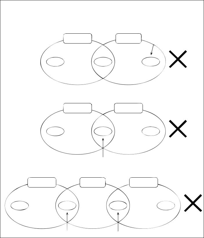
NOTE :
The following group setting cannot be performed.
•Unit groups which are not under the management of the master controller and are managed by the slave system controller.
Master system |
Slave system |
controller |
controller |
Group |
Group |
Group |
• A common group is managed by more than two master controllers.
Master system |
Master system |
controller 1 |
controller 2 |
Group |
Group |
Group |
•A slave system controller which exceeds the management range of the master system controller of two or more.
Master system |
Slave system |
Master system |
controller 1 |
controller |
controller 2 |
Group |
Group |
Group |
Group |
-7-

3 - 2 Display Screen
Display
01 02
PROHI
BITED
Overall status lamp
The lamp indicates the unit operation condition.
ON …… During operation
OFF ……All group are stopping BLINKING ……Malfunction
G-50A
NOTE: The temperature setting includes a function to switch the display between Celsius (˚C) or Fahrenheit (˚F) (page 34).
2 |
1 |
Continuously press
 and
and 
(2 seconds or longer)
ENTER
NEXT
3
4 |
5 |
|

 04-2002 MON


P 4
1
001 |
-8-
Collective operation switch
If this switch is pressed during
the operation, a whole group stop
is performed.
The collective operation switch can be performed in the user setting mode for any screen. ( Excluding menu screen )
LAN changeover switch
Refer to section "5. Initial setting ( page 25 ) " for explanation of the operation of these switches.
LCD contrast adjustment knob
LAN status lamp
Orange LED indicates action and green LED indicates link.
Service LAN connector
Refer to section "5. Initial setting " for an explanation of this connector.
Rear side
Ethernet |
M-NET |
POWER |
|
|
|
A B S |
12VDC GND |
RS232C |
1 CN1 5 1 CN2 9 |
Operation
panel |
RS-232C connector |
|
M-NET Transmission |
|
line terminal |
External input / output interface connecter LAN(Ethernet)connector Refer to section "7. External input / out-
put function ( page 38 )" for the detail of operation of these connectors.
DC power supply terminator
6 ADDRESS SETTING
 7 FUNCTION SETTING
8 IP ADDRESS SETTING
M-NET address setting |
Function select setting |
IP address setting |
|||||||
6 |
|
|
|
|
|
|
|
|
|
ADDRESS SETTING |
FUNCTION SELECTS |
IP ADDRESS SETTING |
|||||||
7 |
1 |
2 |
3 |
4 |
5 |
6 |
7 |
8 |
IP ADDRESS : |
M-NET ADDRESS: 000 |
ON |
|
|
|
|
|
|
|
|
|
|
|
|
|
|
|
192.168.001.001 |
||
8 |
OFF |
|
|
|
|
|
|
|
|
|
|
|
|
|
|
|
|
MASK ADDRESS: |
|
|
|
|
|
|
|
|
|
|
|
|
|
|
|
|
|
|
|
|
255.255.255.000 |
Displays, or sets, the controller |
Sets the function of the controll- |
Sets the LAN IP address. |
M-NET address. |
er.Refer to section "5. Initial set- |
Refer to section "5. Initial setti- |
Refer to section "5. Initial setting |
ting(page 25)" for a detailed ex- |
ng(page 25)" for a detailed ex- |
(page 25)" for a detailed explan- |
planation of operation. |
planation of operation. |
ation of operation. |
|
|
VER. .
BACK
3
4
5
2
|
GROUP NO |
|
|
|
|
|
2002 |
|
|
||||
|
|
|
|
|
|
|
|
|
|
|
|
|
|
|
|
|
|
|
|
|
|
|
|
|
|
|
|
|
|
|
|
|
|
|
|
|
|
|
16-04-2002 |
12 : 45 |
|
|
|
NONE |
|
|
|
|
|
|
014 6602 |
(DETECT 014) |
|||
|
|
|
|
|
|
|
|
|
|
|
2002 |
|
|
|
|
|
INDICATE |
|
|
|
|
||||||
|
|
|
|
|
|
|
|
|
|
|
05-04-2002 |
09 : 12 |
|
|
|
|
INDICATE |
|
012 6607 |
(DETECT 012) |
|||||||
|
1-1-2001 |
|
|
|
2002 |
|
|
||||||
|
|
|
|
|
|
|
|||||||
|
NONE |
|
|
|
|
|
|
||||||
7 TEMP. UNIT |
˚C |
/ ˚F |
|
|
|
||||||||
LOSSNAY |
a |
that |
Maintenance 


-9-
4 . User operation
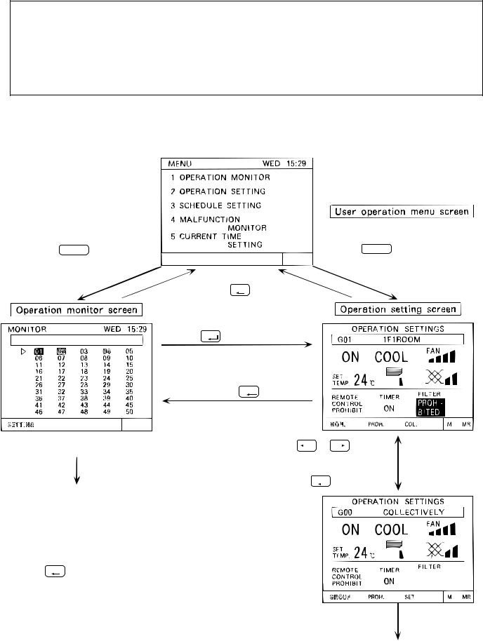
Used the following two screens when user operation is performed.
Operation monitor screen .......This screen displays ON/OFF and malfunction condition of unit.
G-50A normally displays this screen.
Operation setting screen ........ The unit operations can be performed by individual group or collective operation. These operation include the ON/OFF, operation mode, fan speed, temperature setting, air direction, ventilation setting, timer operation ON/OFF, local remote controller prohibition and filter sign reset are performed by group or collectively. In addition, this screen can also displays the room temperature of each group.
•The collective operation can be performed on any screen (except for the menu screen) in the user operation mode
<Shifting to the operation monitor screen and operation setting screen>
Press the 1 |
switch and |
select "1. OPERATION MONITOR"
The unit operation can be verified in a single glance.
Press the 2 |
switch and |
select "2. OPERATION SETTING"
BACK
Press the SCREEN switch.
Press the |
ENTER |
switch. |
|
Press the  or
or  switch to set "MON. (MONITOR)" on the blinking
display and press the ENTER  switch.
Press the |
|
or |
|
|
switch |
(Individual group |
|
|
|
|
operation setting |
||||
|
|
||||||
to set "COL. (COLLECTIVE)" or |
screen) |
||||||
"GROUP" on the blinking display |
|
||||||
and press the |
ENTER |
switch. |
|
||||
|
|
|
|||||
Refer to section "4-1 Operation condition monitor".
<Returning to the user operation menu screen>
BACK
Press the SCREEN (back screen) switch.
Each unit operation setting is performed.
(Collective operation setting screen)
Refer to section "4-2 Operation setting".
-10-
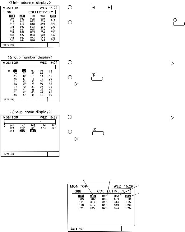
4 - 1 Operation condition monitor
•This function displays the ON/OFF/Malfunction status of specific units or group.
•ON/OFF/Malfunction status is shown by the indication corresponding to the unit or group appearing in inverse, normal or blinking display.
•The user may select display items by unit address, group number or group name. Refer to section "5-7 User setting (page 34)" for detail of user setting.
•During the user operation mode, this screen returns from any screen if there is no operation for approximately 10 minutes.
(1)Operation Method
•Note that operation is different for each of the following display methods.
1 Press the |
GROUP |
switch to change the display group in desired opera- |
SELECT |
tion and monitor.
2 When displaying the units in a given group, press the all the units in that group ON or OFF.
|
ON/OFF |
switch turn |
1 |
|
1 Press the 


 switch to move the " " select the group number to be operated.
2 Press the 1 |
ON/OFF |
switch to set the displayed group unit is indicated by the |
" " symbol to the on/off mode.
1 Press the 


 switch to move the " " symbol. Select the group name to be operated.
2 Press the 1 |
ON/OFF switch to set the displayed group unit is indicated by the |
"" symbol to the on/off mode.
*Displays up to the first 3 characters of the set group name.
(2) Display contents
Reverse:ON Normal:OFF
Blinking: Malfunction during units is off
Blinking and Reverse: Malfunction during unit is on.
*When a malfunction occurs, refer to section "4-4 Malfunction (page 23) ".
-11-
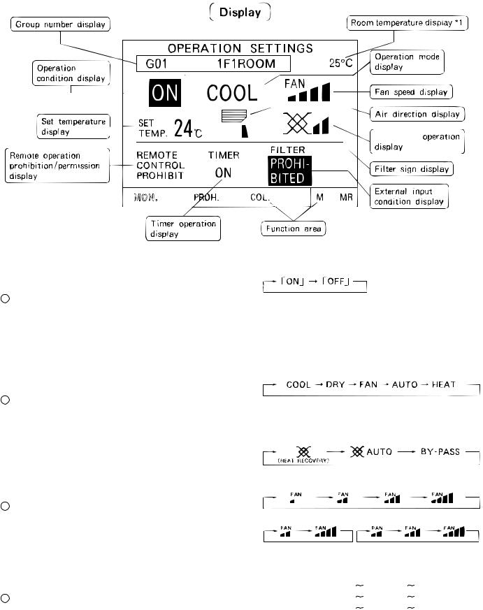
4 - 2 Operation setting
• There are two methods for the operation, performing the operation classified by groups or collective operation.
4 - 2 - 1 Group operation setting
Ventilation
No. |
Name of switches |
Function |
|
|
Display |
|
|
|
|
|
|
|
|||
|
|
|
Operation status display |
|
|||
1 |
ON/OFF switch |
The ON/OFF condition of the dis- |
|
|
|
|
|
played group is switched. |
*When there is an interlocked OA processing unit |
||||||
|
|||||||
|
|
|
or LOSSNAY , turning this switch ON starts |
||||
|
|
|
operation in a [High] ventilated state. |
||||
|
|
|
|
||||
|
|
Used to the type of the operation |
Each time to push the switch, a mode is selected in |
||||
|
|
a sequence that goes from COOL, DRY, FUN, |
|||||
|
|
mode selection. |
|||||
|
|
AUTO, HEAT and beck to AUTO for air conditioner |
|||||
|
|
|
|||||
|
|
Note: |
group. |
|
|
|
|
|
|
|
|
|
|
||
2 |
Operation mode |
Operation mode can be selected ac- |
|
|
|
|
|
cording to the function of unit. |
On the group composed of independent LOSSNAY , |
||||||
switch |
|||||||
|
If the unit is only cooling type. |
||||||
|
|
operation mode is selected in a sequence that goes |
|||||
|
|
HEAT/AUTO mode may not appear |
|||||
|
|
from HEAT RECOVERY,AUTO, BY-PASS and back |
|||||
|
|
on the display. |
|||||
|
|
to HEAT RECOVERY. |
|
|
|||
|
|
Refer to the instruction manual of |
|
|
|||
|
|
|
|
|
|
||
|
|
the air conditioner for more detail. |
|
|
|
|
|
|
|
|
|
|
|
|
|
|
|
|
Fan speed display |
|
|
|
|
|
|
The fan speed can be switched to four |
4 levels |
|
|
|
|
|
Fan speed |
|
|
|
|
||
3 |
levels. Switching may be 3 levels or 2 |
|
|
|
|
||
switch |
levels, depending on the model. |
|
|
|
|
||
|
2 levels |
|
3 levels |
|
|||
|
|
|
|
|
|||
|
|
|
|
|
|||
|
|
|
The setting temperature display. |
|
|||
|
|
|
The setting range change according to the operation |
||||
|
|
|
mode. |
|
|
|
|
|
Temperature |
The setting temperature change is per- |
COOL/DRY |
19 |
30 ˚C / 67 |
87 ˚F |
|
4 |
HEAT |
17 |
28 ˚C / 63 |
83 ˚F |
|||
setting switch |
formed. |
||||||
|
AUTO |
19 |
28 ˚C / 67 |
83 ˚F |
|||
|
|
|
|||||
|
|
|
NOTE: The temperature setting includes a function |
||||
|
|
|
to switch the display between Celsius (°C) |
||||
|
|
|
or Fahrenheit (°F) (page 34). |
|
|||
|
|
|
|
|
|
|
|
-12-
 Loading...