


2408f & 2404f PROFIBUS Communications Handbook |
Contents |
CONTROLLER MODELS 2408f and 2404f
PROFIBUS-DP COMMUNICATIONS HANDBOOK
Contents |
|
|
|
|
|
Page |
Chapter 1 |
INTRODUCTION |
……………………………………………………..…………… |
1-1 |
|
|
|
Chapter 2 |
PRINCIPLES OF OPERATION ………………………..……..…...................… |
2-1 |
||||
Chapter 3 |
WIRING |
………........……………………….………….……………… |
3-1 |
|
||
|
Cable Specifications |
|
|
|
|
3-2 |
Chapter 4 |
CONTROLLER SET UP & NETWORK CONFIGURATION .......................... |
4-1 |
||||
|
Floating Point Data Formats |
|
|
|
4-2 |
|
|
Diagnostic Information |
|
|
|
|
4-3 |
Chapter 5 |
THE WINDOWS CONFIGURATOR |
……...........……………………………… |
5-1 |
|||
|
Installing GSD Files |
|
|
|
|
5-1 |
Chapter 6 |
TROUBLESHOOTING |
…...……………………………………………….......... 6-1 |
|
|||
Chapter 7 |
DEMAND DATA |
......................................................................................... |
|
|
|
7-1 |
Chapter 8 |
TAG ADDRESSES |
...................................................................................... |
|
|
|
8-1 |
Appendix A |
GLOSSARY OF TERMS |
……………………….……………………………..…. |
A-1 |
|
||
Appendix B |
EUROTHERM OFFICE ADDRESSES |
………………………………………….. B-1 |
|
|||
“This product is covered by one or more of the following US Patents:
5,484,206; Additional patents pending.
PDSIO and INSTANT ACCURACY are trademarks of Eurotherm.”
HA026290 |
Issue 1 January, 98. |
Applies to 2408f and 2404f Controllers software versions 3.22 |
i |
2408f & 2404f PROFIBUS Communications Handbook Introduction
CHAPTER 1 INTRODUCTION
This handbook is written for people who need to use a digital communications link and PROFIBUS-DP communication protocols to supervise Eurotherm Controls Series 2000 instruments. The PROFIBUS-DP protocol is supported by Eurotherm instruments carrying the suffix f in their order codes. Specifically 2408f and 2404f controllers.
It has been assumed that the reader has some experience of communication protocols and is familiar with Series 2000 instruments.
Related handbook:
∙Installation and Operation Handbook for 2408 and 2404 Controller, Eurotherm part number HA025132. This gives a full description of how to use the instruments, configuration options and definition of parameters.
Eurotherm Controls accepts no responsibility for any loss or damage caused by mis-application of the information contained in this document.
THE PROFIBUS FAMILY
|
|
Area |
|
|
|
|
Computer |
|
|
Factory |
MMS, TCP/IP Backbone |
|||
Level |
||||
|
|
|
||
|
|
|
|
|
|
|
|
|
CNC |
PC/VME |
|
|
|
Host |
|
|
|||||||||
Cell |
|
|
|
|
|
|
|
|
|
|
|
|
|
|
|
|
|
|
|
|
|
|
|
|
|
PROFIBUS-FMS |
|
|
|
|
|
|
|
|
|
|
|||||
Level |
|
|
|
|
|
|
|
|
|
|
|
|
|
|
|
|
|
|||
|
|
|
|
|
|
|
|
|
|
|
|
|
|
|
|
|
|
|||
|
|
|
|
|
|
|
|
|
|
|
|
|
|
|
|
|
|
|
|
|
|
|
|
|
|
PC |
|
|
PLC |
|
|
|
DCS |
|
|
|
|
||||
|
|
|
|
|
|
|
|
|
|
|
|
|
|
|||||||
|
|
|
|
|
|
|
|
|
|
|
|
|
|
|
|
|
|
|
|
|
Field |
|
|
|
|
|
PROFIBUS-DP |
|
|
|
|
|
|
|
PROFIBUS-PA |
||||||
Level |
|
|
|
|
|
|
|
|
|
|
|
|
|
|
||||||
|
|
|
|
|
|
|
|
|
|
|
|
|
|
|
|
|
|
|||
|
|
|
|
|
|
|
|
|
|
|
|
|
|
|
|
|
|
|||
|
|
Motor |
|
I/O |
|
Temp |
|
|
Field |
|
|
|
|
Trans- |
|
Field |
||||
|
|
Drives |
|
|
Controller |
|
|
Device |
|
|
|
|
mitter |
|
Device |
|||||
|
|
|
|
|
|
|
|
|
|
|
|
|
||||||||
|
|
|
|
|
|
|
|
|
|
|
|
|
|
|
|
|
|
|
|
|
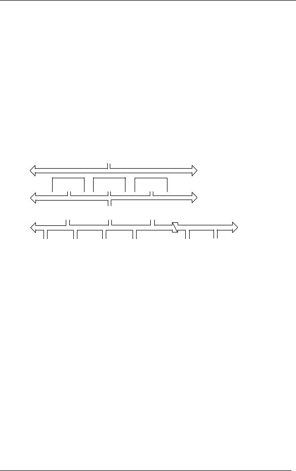
Figure 1-1: PROFIBUS Application Areas
PROFIBUS is a vendor independent, open fieldbus standard for a wide range of applications in manufacturing, process and building automation. Vendor independence and openness are guaranteed by the PROFIBUS standard EN50170. With PROFIBUS, devices from different manufacturers can inter-communicate. Suitable interfaces exist for PLCs, which include the Siemens, Mitsubishi and Allen Bradley range.
The 2400f controllers support the PROFIBUS-DP variant of the PROFIBUS protocol which is designed especially for communication between automatic control systems and distributed I/O at the device level. It is most often used to allow a central Programmable Logic Controller or PC based control system to use external ‘slave’ devices for I/O or specialised functions. The principal advantage is that these devices may be distributed around a machine, thereby saving on the cost of point to point wiring. The ‘open’ nature of the network also permits equipment from different manufacturers to be mixed on the same bus. Additionally, the off-loading of complex and specialised tasks such as PID temperature control lessens the processing load on the central PLC so that its other functions may be carried out more efficiently and require less CPU memory.
PROFIBUS-DP is described in DIN 19245 Part 3, and forms part of EN 50170 with P-Net and WorldFIP. However it is important to note that P-Net and WorldFIP are wholly incompatible with PROFIBUS, using different wiring and transmission technologies.
The PROFIBUS-DP network uses a high speed version of the RS485 standard, permitting baud rates of up to 12Mbaud. Note however, that in order to guarantee electrical isolation standards, the 2400f Series supports rates of up to 1.5 MBaud only. A table of network speed against segment length is given in Chapter 3.
A maximum of 32 PROFIBUS-DP stations (nodes) may be contained within a single network segment. Use of RS485 repeaters allows a total of up to 127 stations.
2408f and 2404f PROFIBUS Communications Handbook |
1-1 |

Introduction |
2408f & 2404f PROFIBUS Communications Handbook |
PROFIBUS-DP is a multimaster, master-slave, token passing network. More detailed information, including a detailed guide to products available, may be obtained from the various world wide PROFIBUS user organisations. You will find contact information in trade magazines or by reference to http://www.profibus.com on the World Wide Web.
PROFIBUS is available in two other types, aimed at different application areas, as follows:
PROFIBUS-PA is designed especially for process automation. It permits sensors and actuators to be connected on one common bus line even in intrinsically safe areas. PROFIBUS PA permits data communication and power over the bus, using intrinsically safe, 2-wire technology according to the international standard IEC 1158-2, but may also be used on the standard RS485 cabling for non-intrinsically safe applications.
PROFIBUS-FMS is the general purpose solution for communication tasks at the cell level.
2400f series controllers may be used on ‘combi’ networks which combine DP and FMS, but may only be used for PA when the intrinsically safe physical medium is not used.
1-2 |
2408f and 2404f PROFIBUS Communications Handbook |

2408f & 2404f PROFIBUS Communications Handbook |
Principles of Operation |
CHAPTER 2 PRINCIPLES OF OPERATION
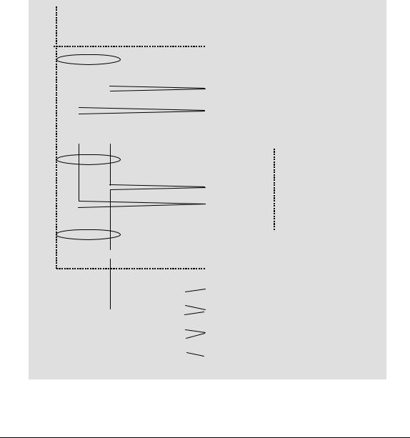
PROFIBUS-DP distinguishes between master devices and slave devices. It allows slave devices to be connected on a single bus thus eliminating considerable plant wiring typical with conventional communications systems. Figure 2-1 compares the two systems.
Master devices determine the data communication on the bus. A master can send messages without an external request when it holds the bus access rights (the token). Masters are also called active stations in the PROFIBUS protocol.
Slave devices are peripheral devices. Typical slave devices include input/output devices, valves, motor drives and measuring transmitters. The 2408f and 2404f series Temperature Controllers are intelligent slaves. This means they will only respond to a master when requested to do so.
PROFIBUS-DP is based around the idea of a ‘cyclical scan’ of devices on the network, during which ‘input’ and ‘output’ data for each device is exchanged.
|
|
|
|
Physical |
|
|
|
|
Actuator 1 |
PLC I/O Mapping |
|
|
Physical |
|
|
|
|
|
|
|
|
|
I/O |
Actuator 2 |
Input |
Output |
PLC |
Mod- |
|
|
|
|||
|
ules |
Physical |
||
Ladder |
|
|
||
|
|
|
||
|
|
|
Actuator 3 |
|
Program |
|
|
|
|
|
|
|
|
|
|
|
|
|
Physical |
|
|
|
|
Actuator 4 |
|
|
|
Figure 2-1a: Plant wiring |
|
I/O scanning |
|
|
conventional comms. systems |
|
|
|
|
|
|
Physical I/O
|
|
|
|
|
|
|
|
Input |
|
|
|
|
Input |
||
Output |
|
|
|
|
|
Output |
|
Slave 1 |
Slave 2 |
Slave 3 |
Slave 4 |
||||
|
|||||||
Figure 2-1: PROFIBUS compared with conventional comms. systems.
I/O Data Exchange
The process of reading the inputs and writing to the outputs is known as an I/O data exchange. Typically, the parameters from each slave device will be mapped to an area of PLC input and output registers, or a single function block, so that the controlling ladder logic or program interfaces with the device as if it were an internally fitted module. It is NOT necessary, therefore, for the programmer to know anything about the physical network. The process of network configuration is usually performed using a PC based program which allows the devices on the network to be defined and device parameters to be mapped into the PLC registers or function blocks.
The cyclical scan occurs in the following order:
1.Values from each slave device, ‘Input Data’, are first scanned over the network into a pre-defined set of input registers in the master controller. Such values might be a set of digital input readings for a digital input unit, or the measured temperature and alarm status from a PID controller.
2.The master then runs its control program, (such as a ladder logic program) using the input data read from the slave devices.
3.The master writes output values (output data) into a pre-defined set of output registers. For example, one of the digital inputs read in the input data might be used to select one of a set of setpoints to be sent to the PID controller.
4.These outputs are then written to each slave device, and the scan-process-write cycle repeats.
2408f and 2404f PROFIBUS Communications Handbook |
2-1 |

Principles of Operation |
2408f & 2404f PROFIBUS Communications Handbook |
Typically no more than 32 bytes of input data and 32 bytes of output data are exchanged for each device during the data exchange. Some PLC masters allow no more than this, although the PROFIBUS-DP standard provides the possibility of transferring 236 bytes in each direction. The input and output data lengths for a given device are variable and it is possible to have devices with only input data, only output data, or both.
The input and output data mixture used by a given slave device is defined by what is known as a GSD file. See Chapter 5 for more details. For simple devices such as digital or analogue I/O blocks, this is fixed. However, since more complex devices often have a much wider choice of possible values to send, it is usually possible to edit the GSD file to change the mapping of device parameters onto Profibus inputs or outputs. This is the case with most Eurotherm implementations, which also allow access to parameter data not in the GSD Input/Output data file. This is called Demand Data and is described further in Chapter 7.
The GSD file is imported into the PROFIBUS Master Network Configuration software before the network is created.
NB: |
PROFIBUS Input Data = Values sent from a device to a master controller or PLC, |
|
PROFIBUS Output Data = Values sent from a master controller or PLC to a device |
2-2 |
2408f and 2404f PROFIBUS Communications Handbook |
2408f & 2404f PROFIBUS Communications Handbook |
Wiring |
CHAPTER 3 WIRING
RS485 is the transmission technology used in 2404f and 2408f PROFIBUS-DP controllers.
Connections are made to the rear terminal block as follows:
Controller Terminal |
Designation |
Function |
HB |
Shield |
RF Ground for cable shielding |
HC |
VP |
5 Volts for termination network only |
HD |
B/B |
RXD/TXD positive |
HE |
A/A |
RXD/TXD negative |
HF |
D Gnd |
0 Volts for termination network only |
Earthing the shield
The PROFIBUS standard suggests that both ends of the transmission line be connected to safety earth. If such a course is followed, care must be taken to ensure that differences in local earth potential do not allow circulating currents to flow, as these can not only induce large common mode signals in the data lines, but can also produce potentially dangerous heating in the cable. Where doubt exists, it is recommended that the shield be earthed at only one section of the network.
Do not connect the shield to DGND.
|
|
|
|
|
|
|
|
|
|
|
Station 1 |
|
|
|
|
|
|
|
|
|
HA |
|
|
A |
|
|
|
B |
|
|
Not connected |
||||
|
|
|
|
|
|
|
|
||||
|
|
|
|
|
|
|
SHIELD |
|
|
|
|
|
|
|
|
|
|
|
|
HB |
Shield |
||
|
|
|
|
|
|
|
|
|
|||
|
|
|
|
|
|
|
|
|
|
|
|
|
|
|
|
|
|
|
|
|
|
|
|
|
|
Twisted |
|
|
|
|
HC |
VP (+5Vdc Voltage Potential) |
|||
|
|
|
|
|
|
|
|
|
|||
|
|
|
pair |
|
|
|
|
|
B |
(Rx/Tx +ve) |
|
|
|
|
|
|
|
HD |
|||||
|
|
|
|
|
|
|
|
|
|||
|
|
|
|
|
|
|
|
|
|
A |
(Rx/Tx -ve) |
|
|
|
|
|
|
|
|
|
|
||
|
|
|
|
|
|
|
|
|
HE |
||
|
|
|
|
|
|
|
|
|
|||
|
|
|
|
|
|
|
|
|
|
DGND (Digital ground) |
|
|
|
|
|
|
|
|
|
|
|
||
|
|
|
|
|
|
|
|
|
HF |
||
A |
|
|
|
B |
|
|
|
|
2408f or 2404f controller |
||
|
|
|
|
|
|
|
|||||
|
|
|
|
|
|
|
|
|
|
|
|
|
|
|
|
|
|
|
|
|
|
|
|
Twisted
pair
Intermediate stations
|
|
|
|
|
|
|
|
|
|
|
|
|
|
|
|
|
|
|
|
|
|
|
|
|
|
|
|
|
|
|
Last Station |
|
|
|
|
|
|
|
|
|
|
|
|
|
HA |
|
|
|
|
|
|
|
|
|
|
|
|
|
|
|
Not connected |
||
|
A |
|
B |
|
|
|
|
|
|
|
|
|
|
||
|
|
|
|
|
|
|
|
|
|||||||
|
|
|
|
|
|
|
|
|
|
|
|
|
|
|
|
|
|
|
|
|
|
|
|
|
|
|
|
|
HB |
Shield |
|
|
|
|
|
|
|
|
|
|
|
|
|
|
|
|
|
|
|
|
|
|
|
|
|
|
|
|
|
|
|
|
|
|
|
|
|
|
|
|
390Ω |
|
|
|
|
|
HC |
VP (+5Vdc Voltage Potential) |
|
|
|
|
|
|
|
|
|
|
|
|
|
|
B |
(Rx/Tx +ve) |
|
|
|
|
|
|
|
|
|
|
|
|
|
|
|||
|
|
|
|
|
|
|
|
|
|
|
|
|
HD |
||
|
|
|
|
|
|
|
|
|
|
|
|
|
|||
|
|
|
|
|
|
|
220Ω |
|
|
|
|
|
|
A |
(Rx/Tx -ve) |
|
|
|
|
|
|
|
|
|
|
|
|
|
HE |
||
|
|
|
|
|
|
|
|
|
|
||||||
Last station only requires |
390Ω |
|
|
|
|
||||||||||
|
|
|
|
|
DGND (Digital ground) |
||||||||||
|
|
|
|
|
|||||||||||
|
|
|
|
HF |
|||||||||||
terminating resistors |
|
|
|
|
|
|
|||||||||
|
|
|
|||||||||||||
|
|
|
|
|
|
|
|
|
|
|
|
|
|
|
2408f or 2404f controller |
|
|
|
|
|
|
|
|
|
|
|
|
|
|
|
|
|
|
|
|
|
|
Figure 3-1: Connection Diagram for up to 32 Slaves. |
|||||||||
CABLE SPECIFICATIONS |
|
|
|
|
|
|
|
|
|
|
|
|
|||
2408f and 2404f PROFIBUS Communications Handbook |
3-1 |

Wiring |
2408f & 2404f PROFIBUS Communications Handbook |
Either of the two cable types detailed below can be used. Please note that the cable types A and B, specified below, are NOT related to the wire numbers A and B in the above wiring diagram. Type A is recommended as it allows higher speed and longer cable length.
|
Type A cable |
Type B cable |
Characteristic |
135 to 165Ω at a frequency of 3 to 20 MHz. |
135 to 165Ω at a frequency of > 100 kHz |
Impedance: |
|
|
|
|
|
Cable |
< 30 pF per Metre |
typ. < 60 pF per Metre |
capacitance: |
|
|
|
|
|
Core diameter: |
max. 0.34 mm², corresponds to AWG 22 |
max. 0.22 mm², corresponds to AWG 24 |
Cable type: |
twisted pair cable. 1x2 or 2x2 or 1x4 lines |
twisted pair cable. 1x2 or 2x2 or 1x4 lines |
|
|
|
Resistance: |
< 110 Ohm per km |
- |
Shielding: |
Copper shielding braid or shielding braid and |
Copper shielding braid or shielding braid and |
|
shielding foil |
shielding foil |
Belden B3079A meets cable A specifications, but there are other choices. For more information refer to the ‘PROFIBUS Product Guide’ produced by the PROFIBUS User Group.
Maximum line length per segment
Baud rate (kbit/sec) |
9.6 |
19.2 |
93.75 |
187.5 |
500 |
1500 |
|
|
|
|
|
|
|
Type A cable |
1200m |
1200m |
1200m |
1000m |
400m |
200m |
Type B cable |
1200m |
1200m |
1200m |
600m |
200m |
- |
3-2 |
2408f and 2404f PROFIBUS Communications Handbook |
2408f & 2404f PROFIBUS Communications Handbook |
Controller Set Up & Network Configuration |
CHAPTER 4 CONTROLLER SET UP & NETWORK CONFIGURATION
PROFIBUS-DP communications is available in Eurotherm 2408f and 2404f controllers. Other 2000 series controllers (i.e. controllers without the f suffix) cannot be converted to PROFIBUS-DP comms, since a different microprocessor board is required.
Main Differences between 2400f Controllers and Other Series 2000 Instruments.
2400f
The 20 program variant is not available
EI Bisynch is not available. The Instrument Programming System software, IPSG, therefore, cannot be used for cloning or configuration.
Module slot H can only be used for PROFIBUS-DP or Modbus communications.
A PROFIBUS-DP module fitted to 2400f may be configured to Modbus communications if required. A Modbus module fitted to any other 2000 series instrument cannot be configured to PROFIBUS-DP.
A PDSIO master or slave module can only be fitted in module slot J.
PROFIBUS-DP may be used with either mains powered and 24V AC/DC controllers, and in all respects, other than those described above, they are standard units and may be used in exactly the same way as other 2400 series controllers.
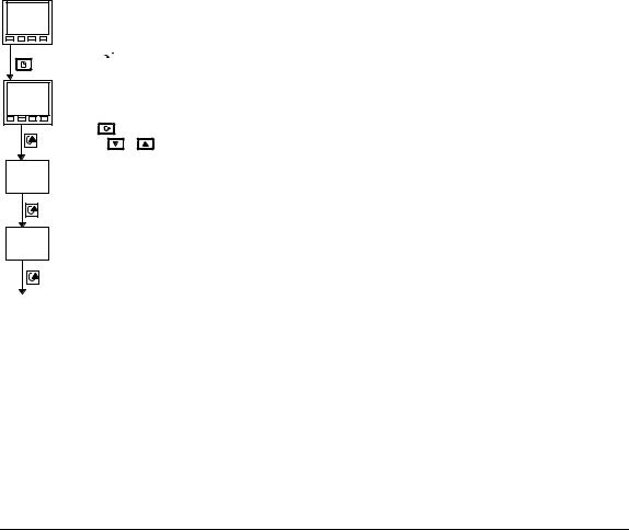
CONTROLLER NODE ADDRESS AND CONFIGURATION
Assigning a Node Address
Connect the controller to the PROFIBUS network as described in Chapter 3.
Every controller on the network must have its own unique address to distinguish it from any other.
D
D
,
)O 6
5
6 6
59.
From the HOME display,
press  until you reach the , list
From the Comms List
Press |
to display the node address. |
|
Press |
or |
to set the desired address. B |
From the Address List
Press  to display the Comms Status This is a read-only diagnostic display 5 A Ready to run
59.Comms running
Press  to return to the HOME display
Note: The baud rate is automatically selected by the master.
2408f and 2404f PROFIBUS Communications Handbook |
4-1 |
Controller Set Up & Network Configuration |
2408f & 2408f PROFIBUS Communications Handbook |
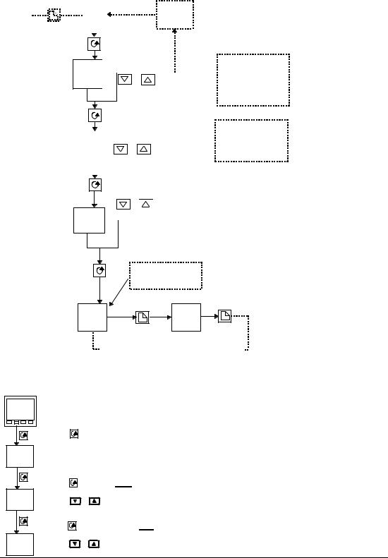
TO CONFIGURE THE CONTROLLER COMMUNICATIONS PARAMETERS
Select Configuration Level
Press Page
“HOME” button display repeatedly
until Access List appears
D |
|
|
If incorrect |
|
|
password |
|||
D |
|
|
|
|
|
)O 6 |
entered |
||
|
|
|||
|
|
|
|
|
|
|
|
|
|
|
|
|
|
|
1st press
2 secs
/

/ or to enter password
(factory default = 1)
0
2nd press
!/6/ |
|
|
/. |
or to select /. |
|
|
|
|
|
|
|
3rd press
If the password has been set to ‘0’ - access is permanently unlocked & the lower readout always shows PASS
Note: Selecting
0 4 9))or O6 will allow direct entry to these levels at this point
/. /.
/.
0
4th press
or
 to enter password
(factory default = 2)
At this point the controller is in configuration level
N. 6 |
N0 |
/. |
/. |
Repeated pressing of “Page” button selects configuration list headings in a continuous loop
Select Comms Configuration List
#/.
|
Press |
to display: Identity of module |
||
O |
This should be a read-only parameter displaying , |
|||
, |
|
|
|
|
|
Press |
to display: Function |
||
9. |
Press |
|
to set 9. = 05/ D This selects PROFIBUS-DP protocol |
|
05/ |
or |
|||
|
Press |
to display: Comms Resolution |
||
5 |
Press |
or |
to select 9)) = Full, or N.6 = Integer 9)) is the recommended setting |
|
8)) |
||||
|
|
|
||
4-2 |
|
|
2408f and 2404f PROFIBUS Communications Handbook |
|

2408f & 2404f PROFIBUS Communications Handbook |
Controller Set Up & Network Configuration |
NETWORK CONFIGURATION
Having wired and configured the controller, the master PLC or PC based supervisory package must be configured to set-up the parameters that it will be able to read and write to. This is known as ‘network configuration’.
The network is configured by importing ‘GSD’ files into your Master PROFIBUS network configuration software: This should be explained in your network configuration software documentation. ‘GSD’ is an acronym of a German phrase meaning ‘Device Database’.
The GSD files supplied with your 2408f and 2404f controllers are created using a Windows-based configuration tool. This software is also separately available under ordering code PROF-ENG.
Two standard GSD files, are supplied on the disc:
EURO2400.GSD - standard parameter mapping. This is the default file, which is pre-configured for commonly used parameters, as shown in Table 4-1 below.
EURD2400.GSD - standard parameter mapping with ‘demand data’, which allows random read/write to any parameter within the controller. This is configured with the same default parameters.
|
PROFIBUS Input Data |
|
PROFIBUS Output Data |
Process Variable |
0; |
Setpoint 1 |
0 |
Working Setpoint |
< 0 |
Setpoint 2 |
0 |
Output 1 |
0 |
Setpoint Select |
) |
Summary Output Status Word |
Acknowledge all Alarms |
||
Table 4-1: Default Parameters.
The Summary Output Status Word is shown in Table 4-2., see ‘PROFIBUS DIAGNOSTICS’
It is possible to edit the above files or create new files using the Windows configurator.
The Master network configuration software uses the GSD files to produce a further file which is downloaded into your master PLC or PC supervisory package. Once the configuration file has been downloaded, you can set the network running. If all is well, the ‘REM’ beacon on the controller will start to flash, indicating that the data exchange is proceeding. The 6 6 parameter in the + list will show 59.. Input data will then be transferred from the controller to the master, and output data will be transferred from the master to the controller.
If all 2400f controllers are of the same type only one GSD file needs to be configured.
FLOATING POINT DATA FORMATS
Data is returned or sent in the form of a single 16 bit integer value (register). Since the controllers use and display floating point values, these are translated into integers in one of two ways, selected in controller configuration.
Full Resolution: The value is returned as a ‘scaled integer’, such that 999.9 is returned or sent as 9999; 12.34 is encoded as 1234. The control program in the PROFIBUS master must convert the numbers into floating point values if required. This is the recommended format and is the factory default.
Integer Resolution. The floating point value is returned as a rounded integer, with the fractional part discarded. For example 999.9 would be returned as 1000; 12.34 would be returned as 12. Similar rules apply to output operations, although note that it is only possible to send integer values so that setpoint values such as 11.5 cannot be used and so either 11 or 12 would have to be chosen instead.
2408f and 2404f PROFIBUS Communications Handbook |
4-3 |
Controller Set Up & Network Configuration |
2408f & 2408f PROFIBUS Communications Handbook |
PROFIBUS DIAGNOSTICS
One of the features of PROFIBUS-DP is that high priority diagnostic information is provided for each slave. The 2400f Series uses the ‘Ext_Diag_Data’ area of this message (bytes 7 and 8) to send a word containing 16 bits of information pertaining to the process and alarm status of the controller: The documentation supplied with your master should provide further details on how to access diagnostic information.
BIT |
|
DESCRIPTION |
0 |
Alarm 1 State ( 0 = Safe 1 = Alarm ) |
|
1 |
Alarm 2 State ( 0 = Safe 1 = Alarm ) |
|
2 |
Alarm 3 State ( 0 = Safe 1 = Alarm ) |
|
3 |
Alarm 4 State ( 0 = Safe 1 = Alarm ) |
|
4 |
Manual Mode ( 0 = Auto 1 = Manual ) |
|
5 |
Sensor Break ( 0 = Good PV 1 = Sensor Broken ) |
|
6 |
Loop Break |
( 0 = Good closed loop 1 = Open Loop ) |
7 |
Heater Fail |
( 0 = No Fault 1 = Load fault detected ) |
8 |
Tune Active |
( 0 = Auto Tune disabled 1 = Auto Tune active) |
9 |
Ramp/Program Complete ( 0 = Running/Reset 1 = Complete ) |
|
10 |
PV out of range ( 0 = PV within table range 1 = PV out of table range ) |
|
11 |
DC control module fault (0= Good. 1= BAD) |
|
12 |
Programmer Segment Synchronise (0 = Waiting, 1 = Running) |
|
13 |
Remote input sensor break (0 = Good, 1 = Bad) |
|
14 |
IP1 Fault |
|
15 |
Reserved |
|
Table 4-2: Summary Output Status Word
A ‘new diagnostics’ event will occur whenever any of the monitored events changes state...
Diagnostics Example
The example below may be returned which gives a summary of the Output Status Word information shown in the table above.
Byte 1 |
Byte 2 |
Byte 3 |
Byte 4 |
Byte 5 |
Byte 6 |
Byte 7 |
Byte 8 |
XX |
XX |
24 |
XX |
XX |
03 |
40 |
30 |
Byte 6 signifies 3 bytes of information are included
Bytes 7 & 8 are 4030Hex or 01 00 00 00 00 11 00 00 Binary
From table 4-1:
Bit 4 is set Bit 5 is set Bit 14 is set
Meaning the controller is in Manual Mode Meaning the controller is in Sensor Break Meaning the controller is in IP1 Fault
Global Commands
This is a further PROFIBUS-DP feature, which is not supported by the 2400f series of temperature controllers.
4-4 |
2408f and 2404f PROFIBUS Communications Handbook |
 Loading...