


EDH-5
Minolta EDH-5, C-403, C-404, FN-7, FN-115 Service Manual
...
EDH-5
C-403/C-404
FN-7/FN-115
Cover Inserter C
PK-3
ZK-2
TMG-2
Option
Service Manual

Dual references may be used on the following:
Official Options name : Popular Options name
EDH-5 : RADF
C-403/C-404 : LT and LCT
FN-115 : FNS
FN-7 : FNS
Cover Inserte Cr : PI
PK-3 : PU
TMG-2 TU
ZK-2 : PZ
In-System Writer : ISW


RADF
EDH-5

RADF

Refer to the Di850 service manual on page.......... S-1
SAFETY AND IMPORTANT WARNING ITEMS
EDH-5
CONTENTS
RADF
1. OUTLINE
PRODUCT SPECIFICATIONS..................................1-1
CENTER CROSS-SECTIONAL DRAWING..............1-2
DRIVE SYSTEM DIAGRAM ......................................1-3
ORIGINAL CONVEYANCE PROCESS.....................1-4
[1] Single side original copy mode (large) .......1-5
[2] Single side original copy mode (small).......1-6
[3] Double side original copy mode (large)......1-7
[4] Double side original copy mode (small) .....1-8
[5] Mixed original copy mode...........................1-9
2. UNIT EXPLANATION
EXTERNAL SECTION...............................................2-1
[1] Composition ...............................................2-1
[2] Mechanisms ...............................................2-1
ORIGINAL FEED/CONVEYANCE/EXIT SECTION...2-2
[1] Composition ...............................................2-2
[2] Mechanisms ...............................................2-2
[3] Original Fe ed/Conveyance/Scan Control ...2-4
[4] Original Reversal and Conveyance
Control........................................................2-7
[5] Original Exit Control ...................................2-9
[6] Original Size Detection Control ................2-11

RADF

1
RADF
OUTLINE

RADF
EDH-5
1-1
RADF
PRODUCT SPECIFICATIONS
[1] Type
Type
Sheet-through type reversible DF
[2] Functions
Original size:
• Metric area
A3 / B4 / A4 / A4R / B5 / B5R / A5 / A5R
11 x 17 / 8.5 x 14 / F4
• Inch area
11 x 17 / 8.5 x 14 / 8.5 x 11 / 8.5 x 11R /
5.5 x 8.5 / 5.5 x 8.5R
A3 / B4 / A4 / B5 / B5R
• All sizes are detected automatically.
• Mixing of original sizes possible.
Original type:
Plain original
50 to 200 g/m
2
or 14 to 45 lbs high quality
paper.
Special original
Original feed and conveyance ability may be
inferior to those of 50 to 130 g/m
2
or 14 to 35
lbs high quality original.
Only SDF mode single-sided passage allowed
for 131 to 200 g/m2 or 35 to 45 lbs thick origi-
nal.
The following types of original cannot be used:
• OHP film
• Blueprint masters
• Label original
•Offset masters
• Bonded originals
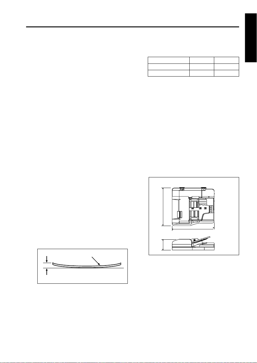
Original curling:
10 mm maximum
Maximum number of stacked originals:
100 sheets maximum (80 g/m
2
or 22 lbs)
Original read speed (copies per minute,
600dpi):
Original feed layout:
Face-up placement, centered, U-turn feed/
straight eject (large size/small size indepen-
dent eject), reversal section placed at ejection
side.
Original image read position:
At the slit glass section
[3] Machine Data
Power source:
DC24 V / 5 V (supplied from the main unit)
Max. power consumption:
Less than 180 VA
Weigh t:
Approx. 21.5 kg
Machine dimensions:
[4] Maintenance
Maintenance : Same as the main body
Service life : Same as the main body
[5] Operating Environment
Temperature:
10 to 30 °C (50 to 86 °F)
Humidity:
10 to 80 % RH
Note: The information herein may be subject to
change for improvement without notice.
Amount of curl
Original
Mode Original size Feed speed
Single sided original A4/8.5x11 85
Double sided original A4/8.5x11 58
Unit: mm
570
170
650
EDH-5
1-2
RADF
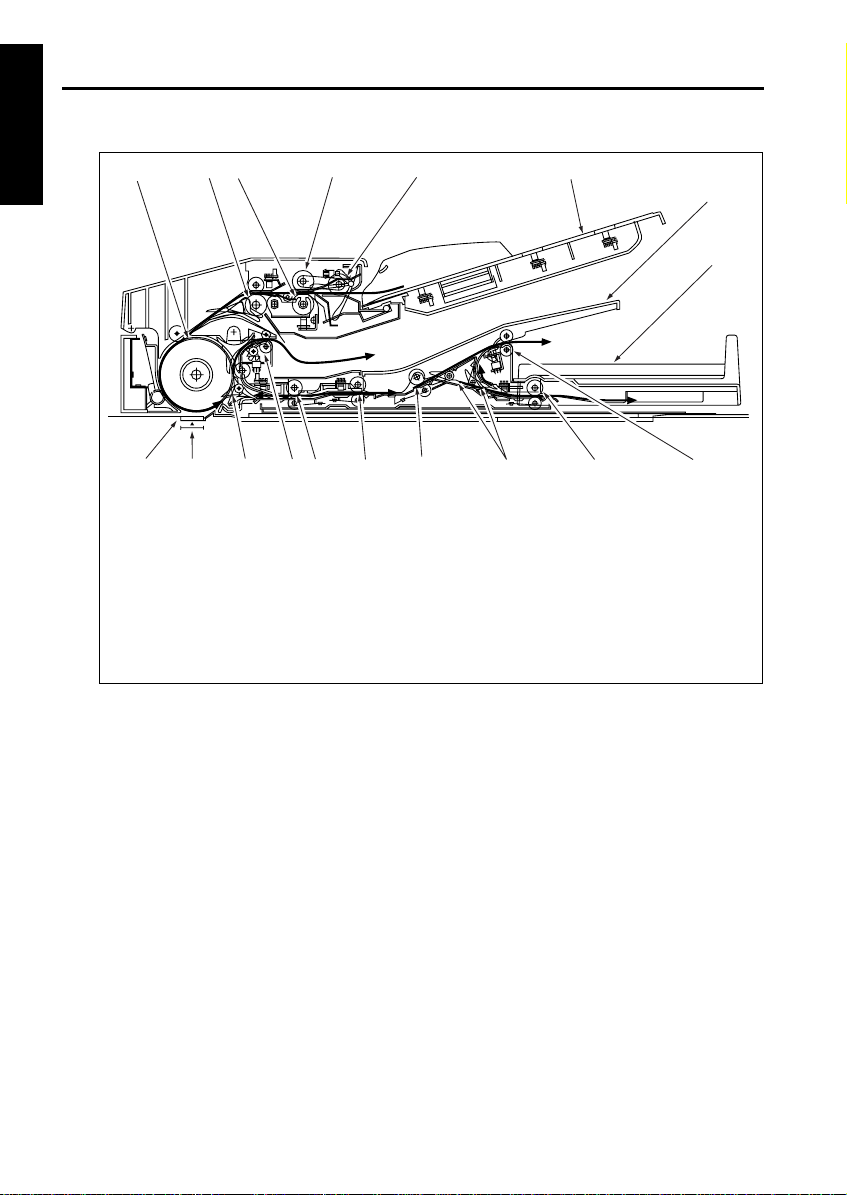
CENTER CROSS-SECTIONAL DRAWING
2
1
12
6
7
5
3
8
9
10
11
18
17
13
14
16
15
4
1. Original conveyance roller
2. Registration roller
3. Double feed prevention roller
4. Separation roller
5. Original feed roller
6. Original feed tray
7. Original exit tray (for large-size original)
8. Original exit section (for small-size original)
9. Original exit roller 2
10. Original exit reversal roller
11. Original exit gate
12. Reversal conveyance roller 2
13. Reversal conveyance roller 1
14. Reversal roller
15. Original exit roller 1
16. Flapper
17. Read position
18. Slit glass
EDH-5
1-3
RADF
DRIVE SYSTEM DIAGRAM
2
1
12
6
7
5
3
8
9
20
10
11
19
18
17
13
14
16
15
4
1. Separation roller
2. Registration roller
3. Flapper drive SD (SD 301)
4. Original conveyance roller
5. Original conveyance motor (M301)
6. Flapper
7. Original feed motor (M302)
8. SDF switching SD (SD304)
9. Tray up/down drive motor (M303)
10. Original feed roller
11. Original exit gate SD (SD303)
12. Original exit gate
13. Pressure roller release SD (SD302)
14. Reversal conveyance roller
15. Original exit roller 1
16. Reversal roller
17. Original exit motor 1 (M304)
18. Original exit motor 2 (M305)
19. Original exit reversal roller
20. Original exit roller 2
FRONT
FRONT
EDH-5
1-4
RADF
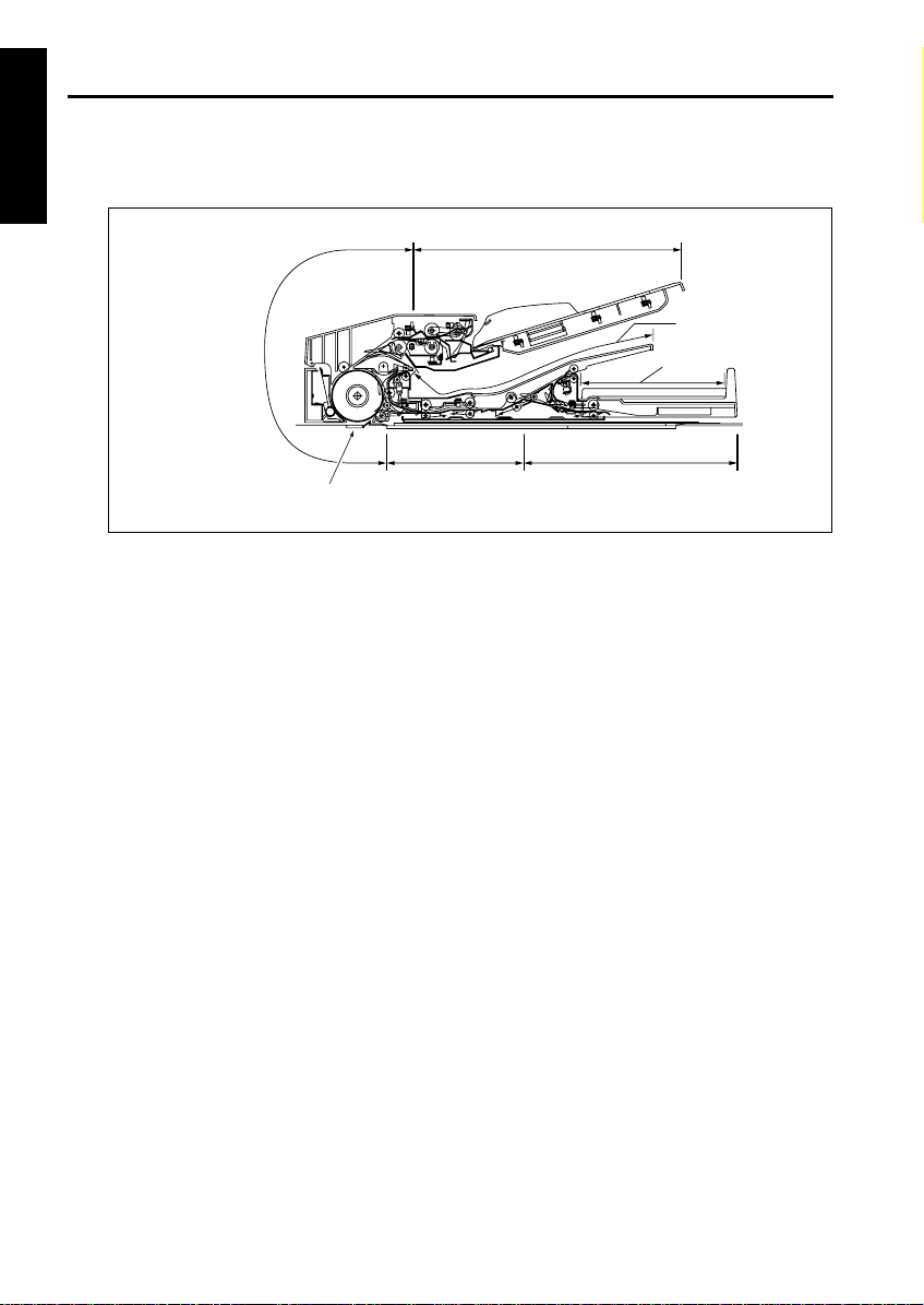
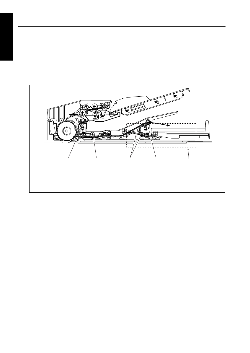
ORIGINAL CONVEYANCE PROCESS
The RADF consists of a original feed section, conveyance section, reversal section, original exit reversal sec-
tion, original exit tray (large), and original exit tray (small).
The original placed faced up on the original feed
tray is fed from the topmost original. The fed orig-
inal is not conveyed to the original glass. Instead,
it is read when it passes the slit glass placed in
the conveyance path.
The RADF operation consists of (a) single side
original copy mode, (b) double side original copy
mode, (c) mixed original copy mode and Z fold
mode. Each has a different conveyance path.
The conveyance path also depends on the orig-
inal size.
Original feed section
Reversal section
Original exit tray
Slit glass (Read section)
Conveyance section
Original exit tray (small)
Original exit reversal section
EDH-5
1-5
RADF
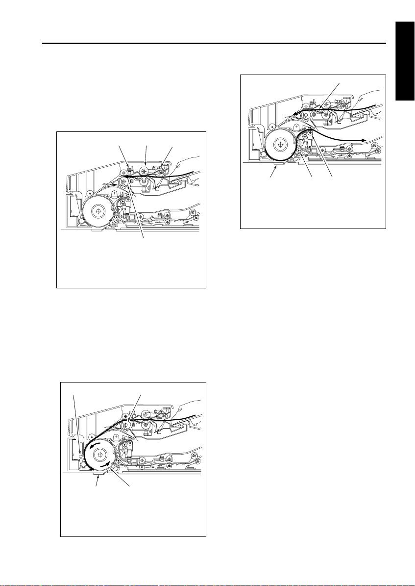
[1] Single side original copy mode (latge)
(single side to single side copy, single side to
double side copy)
The original set in the original feed tray is fed by
the original feed roller and separation roller until
PS306 (original registration detection) turns on.
When PS306 turns on, the registration roller pre-
feeds the original and original is rapidly conveyed
to the conveyance roller. The speed of the con-
veyance roller changes to scan speed at pre-
defined interval after PS306 turns ON and feeds
the original over the slit glass.
At this point, if the next original is present, it is
pre-fed as soon as PS306 detects its leading
edge.
The original is read when it passes over the slit
glass. The original that has been read is con-
veyed along the circumference of the convey-
ance roller by the opening of the flapper, goes
through original exit roller 1, and is exited to the
original exit tray (large).
2
1
3
4
1. Original registration detection PS (PS306
)
2. Separation roller
3. Original feed roller
4. Registration roller
2
1
3
4
1. Original conveyance detection PS (PS308
)
2. Registration roller
3. Original conveyance roller
4. Slit glass
2
1
3
4
1. Next original
2. Original exit roller 1
3. Flapper
4. Slit glass
EDH-5
1-6
RADF
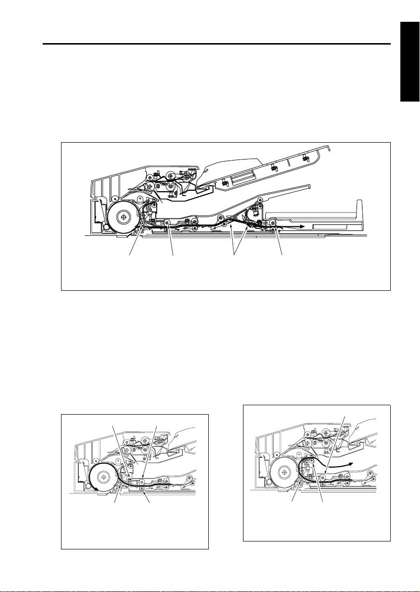
[2] Single side original copy mode (small)
(single side to single side copy, single side to double side copy)
The original feed and conveyance actions up to scanning are performed in the same manner as for single
side original copy mode (large). The original that has been scanned is fed to the original reversal unit by the
reversal roller because the flapper is closed and the paper exit path is blocked. The original fed to the reversal
unit passes through the original exit roller 2 and is exited to the original exit tray (small) since the original exit
gate is closed.
2
1
3
4
Original reversal section
1. Original exit roller 2
2. Original exit gate
3. Reversal roller
4. Flapper
EDH-5
1-7
RADF
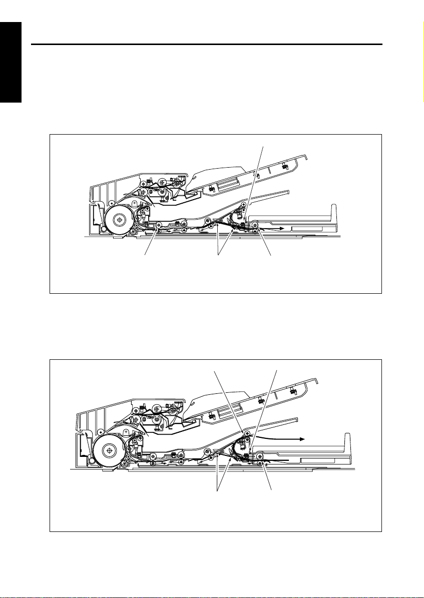
[3] Double side original copy mode (large)
(double side to single side copy, double side to double side copy)
The original conveyance action up to the start of scanning of the front side of the first double side original is
the same as for single side original copy mode (large). The original that has been scanned and read on the
front side is fed by the reversal roller to the reversal unit since the flapper is closed and the original exit path
is blocked. The original fed to the reversal unit does not fit in the reversal unit so the original exit gate opens
to feed it to the original exit reversal section.
When the original reversal detection PS (PS309)
detects the trailing edge of the original and turns
off, the reversal roller changes direction and
feeds the original in the reversal section to the
conveyance roller. Since the original is passed
over the surface of the flapper, it is sent to the
conveyance roller with sides reversed. The orig-
inal reaching the conveyance roller does not exit
the reversal roller so the pressure roller is
released. The conveyance roller feeds this orig-
inal over the slit glass for scanning.
The original that has completed scanning of the
back side is fed inside the reversal unit once
again since the flapper is closed. When PS309
detects the trailing edge of the original and turns
off, the reversal roller changes direction and
feeds the original in the reversal unit to the con-
veyance roller. Since the flapper is now opened,
the original is fed along the flapper, passes
through original exit roller 1, and is exited to the
original exit tray (large).
2
1
3
4
1. Original exit reversal roller
2. Original exit gate
3. Reversal roller
4. Flapper
2
1
3
4
1. Original reversal detection PS (PS309)
2. Reversal roller
3. Pressure roller
4. Flapper
2
1
3
1. Reversal roller
2. Original exit roller 1
3. Flapper
EDH-5
1-8
RADF
[4] Double side original copy mode (small)
(double side to single side copy, double side to double side copy)
The original conveyance action up to the start of scanning of the back side is the same as double side original
copy mode (large). The original that has been scanned and read on the back side is fed by the reversal roller
to the reversal section since the flapper is closed and the original exit path is blocked. Then the original exit
gate opens and the original is fed to the original exit reversal section.
When PS313 (original exit reverse detection) detects the trailing edge of the original and turns off, the original
exit reversal roller changes direction and feeds the original to the original exit gate. Since the original exit
gate is closed, the original passes over the original exit gate and is exited from the original exit roller 2 to the
original exit section (small) with sides reversed.
2
1
3
4
1. Original exit reverse detection PS (PS313)
2. Original exit reversal roller
3. Original exit gate
4. Reversal roller
2
1
3
4
1. Original exit roller 2
2. Original exit reverse detection PS (PS313)
3. Original exit reversal roller
4. Original exit gate

EDH-5
1-9
RADF
[5] Mixed original copy mode
The mixed original copy mode supports both the
same series originals and different series origi-
nals. However, since the size of the original in the
conveyance direction is determined by the ON
interval of PS306, size detection is performed
prior to scanning.
The subsequent operations are the same as
other copy modes.
For details on size detection, refer to section [6]
Original Size Detection Control in section 2.
UNIT EXPLANATION.

RADF

2
RADF
UNIT EXPLANATION

RADF
EDH-5
2-1
RADF
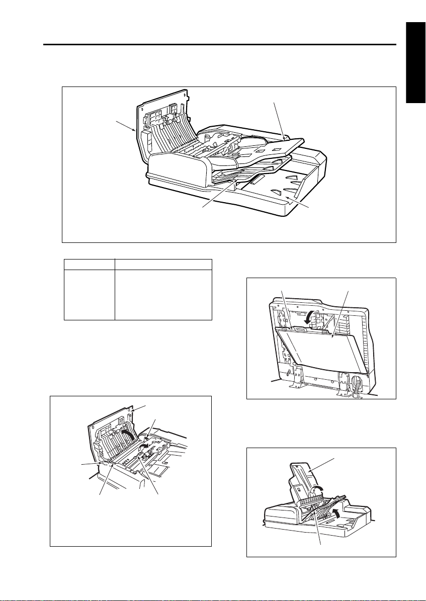
EXTERNAL SECTION
[1] Composition
[2] Mechanism
*1 Jam removal
If an original jam occurs during original feed,
open the Jam access cover and the original con-
veyance guide by releasing the original convey-
ance guide open/close lever, then turn the
jammed original release knob to remove the
jammed original.
If an original jam occurs during original reversal
operation, open the platen guide to remove the
jammed original .
If an original jam occurs during original exit, open
the original feed tray and original exit tray (for
large-size original) to remove the jammed origi-
nal.
2
1
3
4
1. Original feed tray
2. Original exit section (for small-size original)
3. Original exit tray (for large-size original
4. Jam access cover
Mechanism Method
Jam removal
*1
Jam access cover
Jammed original release knob
Original conveyance guide
open/close lever
Platen guide
2
1
3
4
2
1. Jam access cover
2. Original conveyance guide open/close lever
3. Original conveyance guide
4. Jammed original release knob
Lock
Platen guide
Original exit tray (for large-size original)
Original feed tray
EDH-5
2-2
RADF
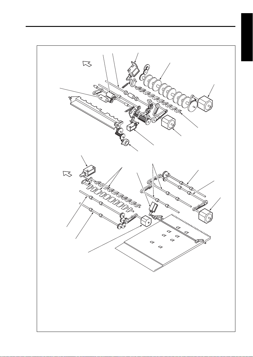
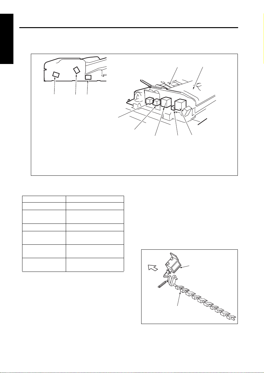
ORIGINAL FEED / CONVEYANCE / EXIT SECTION
[1] Composition
[2] Mechanism
*1 Original conveyance path selection
In the two-sided copy mode, the original convey-
ance path selected after completion of scanning
differs depending on whether the image on the
front surface is to be printed or the image on the
back surface is to be printed. A flapper is used
to switch between these original conveyance
paths. The flapper drive solenoid (SD301) is
turned on/off to switch between the reversal sec-
tion and the original exit section.
2
1
6
7
5
3
8
9
10
4
1. Original exit gate solenoid (SD303)
2. Pressure roller release solenoid (SD302)
3. Flapper drive solenoid (SD301)
4. Original feed tray
5. Jam access cover
6. Original conveyance motor (M301)
7. SDF switching solenoid (SD304)
8. Original feed motor (M302)
9. Original exit motor 1 (M304)
10. Original exit motor 2 (M305)
Mechanism System
Original feed Original feed roller
Double feed preven-
tion
Double feed prevention roller
Separation roller
Original conveyance Original conveyance roller
Original conveyance
path selection *1
Flapper
Original reverse and
feed *2
Reversal roller pressure
Reversal roller rotation
Original exit path
selection *3
Gate 1
Gate 2
FRONT
Flapper
Flapper drive SD
(SD301)
EDH-5
2-3
RADF
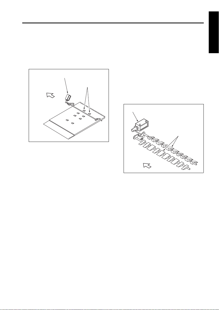
*2 Reversed original feed
In the double-side copy mode, the original fed to
the reversal section is fed back by pressing the
the pressure roller against the reversal roller.
The pressure roller is driven by the pressure
roller release solenoid (SD302).
*3 Original exit path switching
Large-size one-side and two-side originals are
exited to the original exit tray (for large-size orig-
inal). On the other hand, small-size one-side and
two-side originals are exited to the original exit
section (for small-size original) through the rever-
sal section. The small-size two-side original fed
to the reversal section is reversed and exited to
the small size original exit section. The original
exit path switching to which the original is exited
is performed by the gate 1 and gate 2, driven by
the on/off contol of the original exit gate solenoid
(SD303).
FRONT
Pressure roller
Pressure roller release solenoid (SD302)
FRONT
Original exit gate
Original exit gate solenoid (SD303)
EDH-5
2-4
RADF
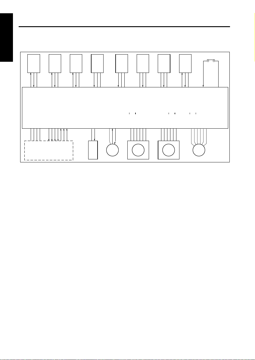
[3] Original Feed / Conveyance / Scan Control
riginal feed is performed by the original feed
roller and separation roller driven by M302 (orig-
inal feed). Original conveyance is performed by
the original conveyance roller driven by M301
(original conveyance).
M301 and M302 are controlled by DFCB (RADF
control board).
1. Operation
a. Sensor activation at power ON
When SW1 (main) is ON, a sensitivity adjust-
ment for PS306 (original registration detection),
PS308 (original conveyance detection), PS311
(original skew detection 1) and PS312 (original
skew detection 2) are performed. However,
automatic adjustment is not performed when the
RADF jam access cover is opened and MS301
(cover open/close MS) is OFF or when there is
original inside the RADF.
b. Pressing original against roller
(1) First original
When a control signal is received from the main
body, M303 (tray up/down drive) turns forward to
raise the original feed tray. By this moment, the
original is raised and pressed against the original
feed roller.
After PS315 (tray upper limit detection) turns
ON, M303 stops after a predefined interval and
leaves the original feed tray raised in standby
state.
After M302 feeds the first original, M303 rotates
backward after a predefined time has elapsed
since it stopped, lowering the original feed tray,
and the pressure on the originals is released.
M303 continues to rotate backward for a pre-
defined interval and then stops and remains in
standby state. At this point the original feed tray
waits without lowering to the bottom.
(2) Second and subsequent originals
When PS308 (original conveyance detection)
detects the leading edge of the first original and
turns ON, M303 that was in standby turns for-
ward to raise the original feed tray and presses
the original against the original feed roller.
Subsequent operations are the same as for the
first original.
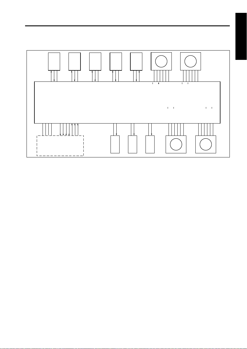
PS312 LED CONT
PS312
5VDC
PS311 LED CONT
PS311
5VDC
PS308 LED CONT
PS308
5VDC
PS301
SGND
5VDC
PS316
SGND
5VDC
5VDC
PS315
SGND
5VDC
PS305
SGND
PS306 LED CONT
PS306
5VDC
MS301
24VDC
DF VALID
DF CTS
DF DTR
DF RXD
24VDC
SD304 DRIVE
PGND
FM301 LD
FM301 DRIVE
M302 DRIVE B
M302 DRIVE B
M302 DRIVE A
M302 DRIVE A
24VDC
24VDC
24VDC
24VDC
M301 DRIVE A
M301 DRIVE A
M301 DRIVE B
M301 DRIVE B
M303 DRIVE B
M303 DRIVE B
M303 DRIVE A
M303 DRIVE A
24VDC
24VDC
5VDC
SGND
24VDC
PGND
DF RTS
DF DSR
DF TXD
DFCB
MAIN BODY
PS312 PS311 PS308 PS301 PS316 PS315 PS305 PS306
SD304
FM301 M302 M301 M303
MS301

EDH-5
2-5
RADF
c. Original feed
M302 drives the original feed roller and separa-
tion roller.
When a control signal from the main body is
received, M302 rotates forward at low speed,
stops, and goes into standby.
When the original feed tray is raised and PS315
turns ON, M302 turns backward after a pre-
defined interval to start original feed operation.
Then, when PS306 (original registration detec-
tion) detects the leading edge of the original and
turns ON, M302 switches to high speed forward
after a predefined interval to complete the origi-
nal feed operation. After completing original feed
at high speed forward, M302 returns to low
speed forward and stops and goes into standby
when PS308 (original conveyance detection)
turns ON.
d. Original conveyance operation
When feeding the first original, M302 transports
the original to the conveyance roller by continu-
ing to rotate at high and low speed.
During this time, M301 (original conveyance)
starts rotating forward at low speed at predefined
time after PS306 turns ON. The original reached
to the conveyance roller is then conveyed to the
scan position.
After starting conveyance of the first original,
M301 continues to rotate forward at low speed
until the last original is scanned.
e. Scan operation
The original is passed over the slit glass of the
optics unit by the low speed forward rotation of
M301 and read (scanned). While the original is
being scanned, original feed and conveyance
operations continue, triggered by the turning ON
of PS308.
f. Original mis-centering detection control
PS311 (original skew detection 1) and PS312
(original skew detection 2) are provided to detect
the inclined leading edge of the original during
conveyance.
PS311 and PS312 are placed at the front and
back of the pre-scan conveyance path and deter-
mine the inclination of the original by measuring
the difference in interval at which the leading
edge of the original turns these switches ON. A
skewed image caused by original inclination is
corrected through image processing so that the
image on the original is copied to a copy paper as
it is on the original.
g. SDF (Single Document Feeder) control
When SDF mode is selected, SD304 (SDF
switching SD) cut the drive force to the double
feed prevention roller to facilitate original feed-
ing.
(1) ON timing
At the start of original feed
(2) OFF timing
When PS306 turns OFF
h. FM301 (ADF fan) operation
FM301 is used to cool M301 so that M301 does
not overheat during operation.
(1) ON timing
At the start of original feed
(2) OFF timing
When original ejection completed.
i. Jammed original ejection control
Upon receiving a control signal from the main
body, M301 rotates at high speed forward,
attempting to eject a jammed original in the
RADF.
2. Signals
a. Input signal
(1) MS301 (MS301 to DFCB)
Jam access cover open/close detection signal.
[L]: Cover opened
[H]: Cover closed
(2) PS301 (PS301 to DFCB)
RADF open/close detection signal.
[L]: RADF closed
[H]: RADF opened
(3) PS305 (PS305 to DFCB)
No original on original feed tray detection signal.
[L]: Original present
[H]: No original
(4) PS306 (PS306 to DFCB)
Original feed over original conveyance roller
detection signal.
[L]: Original present
[H]: No original
(5) PS308 (PS308 to DFCB)
Pre-scan position original detection signal.
[L]: Original present
[H]: No original

EDH-5
2-6
RADF
(6) PS311 (PS311 to DFCB)
Front side original skew detection signal.
[L]: Original present
[H]: No original
(7) PS312 (PS312 to DFCB)
Rear side original skew detection signal.
[L]: Original present
[H]: No original
(8) PS315 (PS315 to DFCB)
Original feed tray upper limit detection signal.
[L]: Tray at upper limit
[H]: Tray not at upper limit
(9) PS316 (PS316 to DFCB)
Original feed tray lower limit detection signal.
[L]: Tray at lower limit
[H]: Tray not at lower limit
(10) FM301 LD (FM301 to DFCB)
Goes [L] when FM301 reaches predefined
speed.
(11) DF TXD (MAIN BODY to DFCB)
Serial data for transmitting main body PRCB
operating status to RADF.
(12) DF RTS (MAIN BODY to DFCB)
Send the Request To Send signal from main
body PRCB to RADF.
(13) DF DSR (MAIN BODY to DFCB)
Send the Data Set Ready signal from main body
PRCB to RADF.
b. Output signals
(1) PS306 LED CONT (DFCB to PS306)
Reflective sensor PS306 LED ON/OFF control
signal.
[L]: PS306 LED ON
[H]: PS306 LED OFF
(2) PS308 LED CONT (DFCB to PS308)
Reflective sensor PS308 LED ON/OFF control
signal.
[L]: PS308 LED ON
[H]: PS308 LED OFF
(3) PS311 LED CONT (DFCB to PS311)
Reflective sensor PS311 LED ON/OFF control
signal.
[L]: PS311 LED ON
[H]: PS311 LED OFF
(4) PS312 LED CONT (DFCB to PS312)
Reflective sensor PS312 LED ON/OFF control
signal.
[L]: PS312 LED ON
[H]: PS312 LED OFF
(5) M301 DRIVE (DFCB to M301)
M301 A phase drive signal.
(6) M301 DRIVE (DFCB to M301)
M301 B phase drive signal.
(7) M302 DRIVE (DFCB to M302)
M302 A phase drive signal.
(8) M302 DRIVE (DFCB to M302)
M302 B phase drive signal.
(9) M303 DRIVE (DFCB to M303)
M303 A phase drive signal.
(10) M303 DRIVE (DFCB to M303)
M303 B phase drive signal.
(11) FM301 DRIVE (DFCB to FM301)
FM301 ON/OFF drive signal.
[L]: FM301 ON
[H]: FM301 OFF
(12) DF TXD (DFCB to MAIN BODY)
Serial data for transmitting RADF operating sta-
tus to main body PRCB.
(13) DF DTR (DFCB to MAIN BODY)
Send the Data Terminal Ready signal from
RADF to main body PRCB.
(14) DF CTS (DFCB to MAIN BODY)
Send the Clear To Send signal from RADF to
main body PRCB.
(15) DF VALID (DFCB to MAIN BODY)
Image forming start signal.
A, A
B, B
A, A
B, B
A, A
B, B
EDH-5
2-7
RADF
[4] Original Reversal and Conveyance Control
In two side copy mode, an original that has been
scanned on the front side is conveyed to the orig-
inal reversal section to be reversed and then res-
canned.
At entrance to the original reversal section, there
is a flapper to switch the original conveyance
path. The flapper is driven by SD301 (flapper
drive). The reversal roller, which reverses and
conveys front-side-scanned original to the origi-
nal reversal section and feeds that original to the
scan section again, is driven by M304 (original
exit 1). The original reversal roller which conveys
original to the original reversal section is driven
by M305 (original exit 2). When reversing and
feeding large originals, the pressure roller is
released by SD302 (pressure roller release).
M304, M305, SD301, and SD302 are controlled
by DFCB (RADF control board).
1. Operation
a. Sensor activation during power ON
When SW1 (main) is turned ON, a sensitivity
adjustment for PS309 (original reversal detec-
tion) and PS313 (original exit reverse detection)
are performed. However, automatic adjustment
is not performed when the RADF jam access
cover is opened and MS301 (cover open/close
MS) is OFF or when there is original inside the
RADF.
b. Original conveyance path switching/reversal
and original feed operation
(1) Small size original
SD301 is always OFF and the flapper is closed.
Therefore, the scanned original, whether it is sin-
gle side or double side, is conveyed to the rever-
sal section by M304 rotating at low speed
forward.
When copying the back side of a double-side
original, at predefined interval after PS309 (orig-
inal reversal detection) detects the trailing edge
of original and turns OFF, M304 rotates back-
ward at low speed and then at high speed to
reverse and feed the original. The reversed orig-
inal is conveyed through the flapper and the
guides to the conveyance roller.
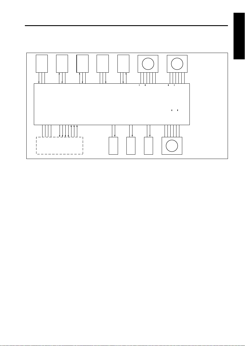
PS308 LED CONT
PS308
5VDC
PS309 LED CONT
PS309
5VDC
PS304 LED CONT
PS304
5VDC
PS306 LED CONT
PS306
5VDC
5VDC
PS313
PS313 LED CONT
M305 DRIVE B
M305 DRIVE B
M305 DRIVE A
M305 DRIVE A
24VDC
24VDC
M304 DRIVE B
M304 DRIVE B
M304 DRIVE A
M304 DRIVE A
24VDC
24VDC
DF VALID
DF CTS
DF DTR
DF RXD
24VDC
SD301 DRIVE
24VDC
SD302 DRIVE
24VDC
SD303 DRIVE
M302 DRIVE B
M302 DRIVE B
M302 DRIVE A
M302 DRIVE A
24VDC
24VDC
24VDC
24VDC
M301 DRIVE A
M301 DRIVE A
M301 DRIVE B
M301 DRIVE B
5VDC
SGND
24VDC
PGND
DF RTS
DF DSR
DF TXD
DFCB
MAIN BODY
PS308 PS309 PS304 PS306
PS313
SD301 SD302 SD303
M302 M301
M304M305

EDH-5
2-8
RADF
(2) Large size original
The scanned-single side original is conveyed to
the original exit tray (large) by the original con-
veyance roller since SD301 is ON and the flapper
is opened.
In the case of large double-side original, the orig-
inal is conveyed to the reversal section when
SD301 turns OFF after scanning the front side of
a double-side original . The original reaching the
reversal section does not fit in the reversal sec-
tion so it is fed to the large-size original exit tray
side by the large original reversal roller, which is
driven by M305 (original exit 2). During this time,
SD303 (original exit gate) turns ON and the orig-
inal exit gate is closed.
The original conveyed to the reversal section is
reversed and fed to the scan section again in the
same manner as small originals. Since the orig-
inal reaching the conveyance roller does not exit
the reversal roller, SD302 is turned ON at pre-
defined interval after high speed backward rota-
tion of M304 to release the pressure roller for the
reversal roller. This enables original conveyance
using the conveyance roller. SD302 turns OFF
when it detects an image scan complete signal
from the main unit.
c. Two side original next original feed operation
(1) Small size original
During front-side scanning of two-side original,
the original feed of the next one is started by the
rotation of M302 (original feed) when PS306
(original registration detection) detects the trail-
ing edge of the previous original and turns OFF.
The next original stops and waits in standby at
predefined interval after the turning ON of PS306
by its own leading edge.
When the back side of the first original is
scanned and PS308 (original conveyance detec-
tion) turns ON, M302 turns ON after a predefined
interval to resume original feed to scan the front
side of the next original. Thereafter, the same
operation is repeated.
(2) Large size original
During front-side scanning of double-side origi-
nal, the original feed of the next original is started
when PS306 (original registration detection)
detects the trailing edge of the previous original
and turns OFF. The next original stops and waits
in standby at predefined interval after the turning
ON of PS306 by its own leading edge.
During ejection of previous original by reverse
and exit operation, when PS309 (original rever-
sal detection) detects the trailing edge of the pre-
vious original and turns OFF, M302 turns ON
after a predefined interval to resume original
feeding to scan the front side of the next original.
Thereafter, the same operation is repeated.
Note: See [5] Original Exit Control for informa-
tion on reverse and exit operation.
d. Jammed original ejction control
Upon receiving a control signal from the main
unit, M304 and M305 rotate at high speed for-
ward, attempting to eject a jammed original in the
RADF.
2. Signals
a. Input signals
(1) PS304 (PS304 to DFCB)
Reversal section original detection signal.
[L]: Original present
[H]: No original
(2) PS309 (PS309 to DFCB)
Reversal section entrance original detection sig-
nal.
[L]: Original present
[H]: No original
(3) PS313 (PS313 to DFCB)
Original ejection reversal section original detec-
tion signal.
[L]: Original present
[H]: No original
b. Output signal
(1) M304 DRIVE (DFCB to M304)
M304 A phase drive signal.
(2) M304 DRIVE (DFCB to M304)
M304 B phase drive signal.
(3) M305 DRIVE (DFCB to M305)
M305 A phase drive signal.
(4) M305 DRIVE (DFCB to M305)
M305 B phase drive signal.
A, A
B, B
A, A
B, B
EDH-5
2-9
RADF
[5] Original Exit Control
The ejection destination of the original that has
been scanned depends on the size of original.
The original exit roller 1 which conveys the orig-
inal to the original exit tray (large) is driven by
M304 (original exit 1). The original exit roller 2
which conveys the original to the original exit
section (small) is driven by M305 (original exit 2).
The flapper which switches the original exit path
and the original exit gate are driven by SD301
(flapper drive) and SD303 (original exit gate)
respectively.
M304, M305, SD301, and SD303 are controlled
by DFCB (RADF control board).
1. Operation
a. Small size original exit operation
(1) Single-side original
Scanned original is conveyed to the reversal sec-
tion since SD301 is OFF and the flapper is
closed.
Original conveyed to the reversal section is con-
veyed to the original exit gate by the reversal
roller which is driven by M304. During this time,
M304 drives the conveyance roller with low
speed forward rotation.
The original is conveyed to the original exit roller
2 since SD303 is OFF and the original exit gate
is opened. M305 drives the original exit roller 2
with low speed forward rotation and ejects the
original to the original exit section (small) with the
original surface facing down.
(2) Two-side original
A original that has been scanned on the back
side is conveyed to the original exit gate in the
same manner as single-side original. During this
time, SD303 is ON and the original exit gate is
closed. Therefore, the original is passed through
the original exit reversal roller, which is driven by
the low speed forward rotation of M305, and con-
veyed to the original exit reversal section.
M305 turns OFF when PS313 ( original exit
reverse detection) is turned OFF by the con-
veyed original. When SD303 turns OFF and the
original exit gate opens, M305 starts high speed
backward rotation after a predefined interval and
reverses the direction of the conveyed original.
Since the original exit gate is opened, the original
is conveyed to the original exit section (small)
rather than returning to the reversal section.
As a result, the two-side original is ejected with
the front side facing down.
PS307
SGND
5VDC
PS309 LED CONT
PS309
5VDC
PS304 LED CONT
PS304
5VDC
5VDC
SGND
PS314
5VDC
PS313
PS313 LED CONT
M305 DRIVE B
M305 DRIVE B
M305 DRIVE A
M305 DRIVE A
24VDC
24VDC
M304 DRIVE B
M304 DRIVE B
M304 DRIVE A
M304 DRIVE A
24VDC
24VDC
DF VALID
DF CTS
DF DTR
DF RXD
24VDC
SD301 DRIVE
24VDC
SD302 DRIVE
24VDC
SD303 DRIVE
24VDC
24VDC
M301 DRIVE A
M301 DRIVE A
M301 DRIVE B
M301 DRIVE B
5VDC
SGND
24VDC
PGND
DF RTS
DF DSR
DF TXD
DFCB
MAIN BODY
PS307 PS309 PS304
PS314 PS313
SD301 SD302 SD303
M301
M305 M304
 Loading...