


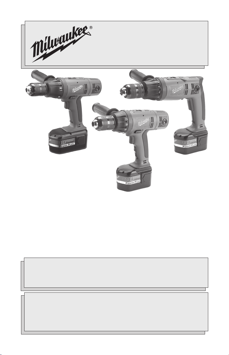
Hammer Drill
OPERATOR'S MANUAL
MANUEL de L'UTILISATEUR
MANUAL del OPERADOR
TO REDUCE THE RISK OF INJURY, USER MUST READ AND UNDERSTAND
OPERATOR'S MANUAL.
AFIN DE RÉDUIRE LE RISQUE DE BLESSURES, L'UTILISATEUR DOIT LIRE ET
BIEN COMPRENDRE LE MANUEL DE L'UTILISATEUR.
PARA REDUCIR EL RIESGO DE LESIONES, EL USUARIO DEBE LEER Y
ENTENDER EL MANUAL DEL OPERADOR.
14.4 V AND 18 V LOKTOR 1/2" HAMMER-DRILLS & DRIVER DRILLS
MARTEAUX PERFORATEURS ET TOURNEVIS ELECTRIQUES 14,4 V
ET 18 V 13 mm (1/2") LOKTOR
MARTILLOS PERFORADORES Y MARTILLOS TALADRADORES DE
13 mm (1/2") LOKTOR Y 14,4 V Y 18 V
0613-20 LokTor Hammer-Drill
0614-20 LokTor Hammer-Drill
0616-20 LokTor Driver Drill
0622-20 LokTor Driver Drill
0624-20 LokTor Hammer-Drill
Catalog No.
No de Cat.
Catálogo No.
SPECIAL NOTE: New battery packs are not fully charged. Charge your battery pack before using it for the first time and
follow the charging instructions in your charger manual.
NOTE SPÉCIALE: Les batteries neuves ne sont pas entièrement chargées. Chargez la batterie avant de vous en servir la
première fois en suivant les instructions de recharge dans le manuel qui accompagne cet outil.
NOTA ESPECIAL: Las batterias, cuando son nuevas, no están totalmente cargadas. Cargue su bateria antes de usarla
por primera vez siga las instrucciones de carga que vienen en el manuel de la herramienta.
2
WORK AREA
ELECTRICAL SAFETY
PERSONAL SAFETY
WARNING!
READ AND UNDERSTAND ALL INSTRUCTIONS.
Failure to follow all instructions listed below, may result in
electric shock, fire and/or serious personal injury.
SAVE THESE INSTRUCTIONS
GENERAL SAFETY RULES-FOR ALL BATTERY OPERATED TOOLS
1. Keep your work area clean and
well lit. Cluttered benches and dark
areas invite accidents.
2. Do not operate power tools in ex-
plosive atmospheres, such as in
the presence of flammable liq-
uids, gases, or dust. Power tools
create sparks which may ignite the
dust or fumes.
3. Keep bystanders, children, and
visitors away while operating a
power tool. Distractions can cause
you to lose control. Protect others in
the work area from debris such as
chips and sparks. Provide barriers or
shields as needed.
4. Do not abuse the cord. Never use
the cord to carry the tool. Keep
cord away from heat, oil, sharp
edges, or moving parts. Replace
damaged cords immediately.
Damaged cords may create a fire.
5. A battery operated tool with inte-
gral batteries or a separate
battery pack must be recharged
only with the specified charger
for the battery. A charger that may
be suitable for one type of battery may
create a risk of fire when used with
another battery.
6. Use battery operated tool only
with specifically designated bat-
tery pack. Use of any other batteries
may create a risk of fire.
7. Stay alert, watch what you are do-
ing, and use common sense when
operating a power tool. Do not use
tool while tired or under the in-
fluence of drugs, alcohol, or medi-
cation. A moment of inattention while
operating power tools may result in
serious personal injury.
8. Dress properly. Do not wear loose
clothing or jewelry. Contain long
hair. Keep your hair, clothing, and
gloves away from moving parts.
Loose clothes, jewelry, or long hair
can be caught in moving parts.
9. Avoid accidental starting. Be sure
switch is in the locked or off po-
sition before inserting battery
pack. Carrying tools with your finger
on the switch or inserting the battery
pack into a tool with the switch on
invites accidents.
10. Remove adjusting keys or
wrenches before turning the tool
on. A wrench or a key that is left at-
tached to a rotating part of the tool
may result in personal injury.
11. Do not overreach. Keep proper
footing and balance at all times.
Proper footing and balance enable bet-
ter control of the tool in unexpected
situations.
12. Use safety equipment. Always
wear eye protection. Dust mask,
nonskid safety shoes, hard hat, or
hearing protection must be used for
appropriate conditions.

3
TOOL USE AND CARE
13. Use clamps or other practical way
to secure and support the work-
piece to a stable platform. Holding
the work by hand or against your body
is unstable and may lead to loss of
control.
14. Do not force tool. Use the correct
tool for your application. The cor-
rect tool will do the job better and safer
at the rate for which it is designed.
15. Do not use tool if switch does not
turn it on or off. A tool that cannot
be controlled with the switch is dan-
gerous and must be repaired.
16. Disconnect battery pack from tool
or place the switch in the locked
or off position before making any
adjustments, changing accesso-
ries, or storing the tool. Such pre-
ventive safety measures reduce the
risk of starting the tool accidentally.
17. Store idle tools out of reach of
children and other untrained per-
sons. Tools are dangerous in the
hands of untrained users.
18. When battery pack is not in use,
keep it away from other metal ob-
jects like: paper clips, coins, keys,
nails, screws, or other small
metal objects that can make a
connection from one terminal to
another. Shorting the battery termi-
nals together may cause sparks,
burns, or a fire.
19. Maintain tools with care. Keep cut-
ting tools sharp and clean. Prop-
erly maintained tools with sharp cut-
ting edge are less likely to bind and are
easier to control.
20. Check for misalignment or bind-
ing of moving parts, breakage of
parts, and any other condition that
may affect the tool's operation. If
damaged, have the tool serviced
before using. Many accidents are
caused by poorly maintained tools. Do
not use a damaged tool. Tag damaged
tools “Do not use” until repaired.
21. Use only accessories that are rec-
ommended by the manufacturer
for your model. Accessories that
may be suitable for one tool may cre-
ate a risk of injury when used on an-
other tool.
SERVICE
22. Tool service must be performed
only by qualified repair person-
nel. Service or maintenance per-
formed by unqualified personnel may
result in a risk of injury.
23. When servicing a tool, use only
identical replacement parts. Fol-
low instructions in the Mainte-
nance section of this manual. Use
of unauthorized parts or failure to fol-
low Maintenance Instructions may cre-
ate a risk of shock or injury.
4
SPECIFIC SAFETY RULES
1. Maintain labels and nameplates. These carry important information. If unreadable
or missing, contact a
MILWAUKEE
service facility for a free replacement.
2. WARNING! Some dust created by power sanding, sawing, grinding, drilling, and other
construction activities contains chemicals known to cause cancer, birth defects or
other reproductive harm. Some examples of these chemicals are:
• lead from lead-based paint
• crystalline silica from bricks and cement and other masonry products, and
• arsenic and chromium from chemically-treated lumber.
Your risk from these exposures varies, depending on how often you do this type of
work. To reduce your exposure to these chemicals: work in a well ventilated area,
and work with approved safety equipment, such as those dust masks that are specially
designed to filter out microscopic particles.
3. Hold tool by insulated gripping surfaces when performing an operation
where the cutting tool may contact hidden wiring. Contact with a “live” wire
will make exposed metal parts of the tool “live” and shock the operator.
4. Keep hands away from all cutting edges and moving parts.
5. Wear ear protectors when using the tool for extended periods. Prolonged
exposure to high intensity noise can cause hearing loss.
Specifications
Cat. No.
0613-20
0614-20
0616-20
0622-20
0624-20
Volts DC
14.4
14.4
14.4
18
18
No Load RPM
Low 0-500
High 0-1700
Low 0-500
High 0-1700
Low 0-500
High 0-1700
Low 0-500
High 0-1700
Low 0-500
High 0-1700
No Load Blows
per Minute
Low 0-7500
High 0-25500
Low 0-7500
High 0-25500
N/A
N/A
Low 0-7500
High 0-25500
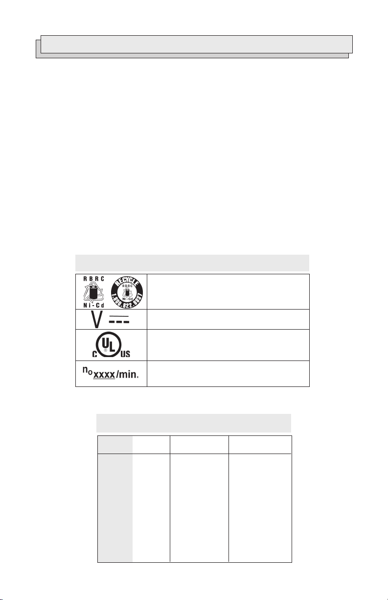
Direct Current
Properly Recycle Nickel Cadmium Batteries
Symbology
Underwriters Laboratories, Inc.
No Load Revolutions per Minute (RPM)
5
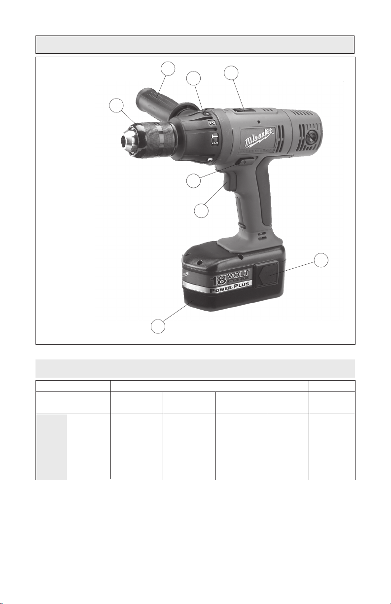
FUNCTIONAL DESCRIPTION
1
2
3
4
5
6
8
1. Speed selector
2. Battery latch
3. Battery pack
4. Trigger
5. Control switch
6. Keyless chuck
7. Side handle
8. Torque selector collar
7
Capacities
Steel
1/2"
1/2"
1/2"
1/2"
1/2"
Wood
Flat Bit
1-1/2"
1-1/2"
1-1/2"
1-1/2"
1-1/2"
Auger Bit
1-1/8"
1-1/8"
1-1/8"
1-1/8"
1-1/8"
Hole Saw
2-1/8"
2-1/8"
2-1/8"
2-1/8"
2-1/8"
Screws
(dia.)
1/4"
1/4"
1/4"
1/4"
1/4"
Masonry
3/8"
3/8"
N/A
N/A
3/8"
0613-20
0614-20
0616-20
0622-20
0624-20
6
Charge your battery pack before you use
your tool for the first time and when your
tool no longer performs with the power
and torque needed for the job. Never
completely discharge the battery pack.
Standard charging time will vary accord-
ing to the type of charger you use. The
charging time will also vary depending on
the supply voltage and charge needed. For
example, if your battery pack does not
require a full charge, charging time will be
less.
FOR SPECIFIC CHARGING INSTRUCTIONS,
PLEASE READ THE CHARGER
OPERATOR'S MANUAL SUPPLIED WITH
YOUR CHARGER.
Battery packs are affected by tempera-
ture. Your battery pack will perform best
and have longest life if it is charged when
the temperature is between 60°-80°F (15°-
27°C). Do not charge in temperatures be-
low 40°F (5°C) or above 105°F (40°C).
Under these conditions, capacity will be
reduced. (See “Maintenance").
CHARGING & USING BATTERY PACKS
WARNING!
Charge only
MILWAUKEE
12, 14.4
and 18 Volt battery packs in charg-
ers. Other types of batteries may
explode causing personal injury
and damage.
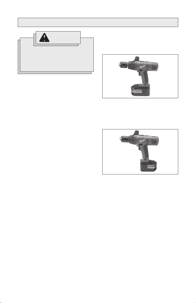
Inserting Battery Pack into Tool
(Fig. 1 & 2)
Battery pack can be inserted into the tool
in two ways.
1. For working in restricted spaces.
Insert the battery pack from the front
by sliding battery pack into the body of
the tool. Insert the battery pack until
the battery latches lock.
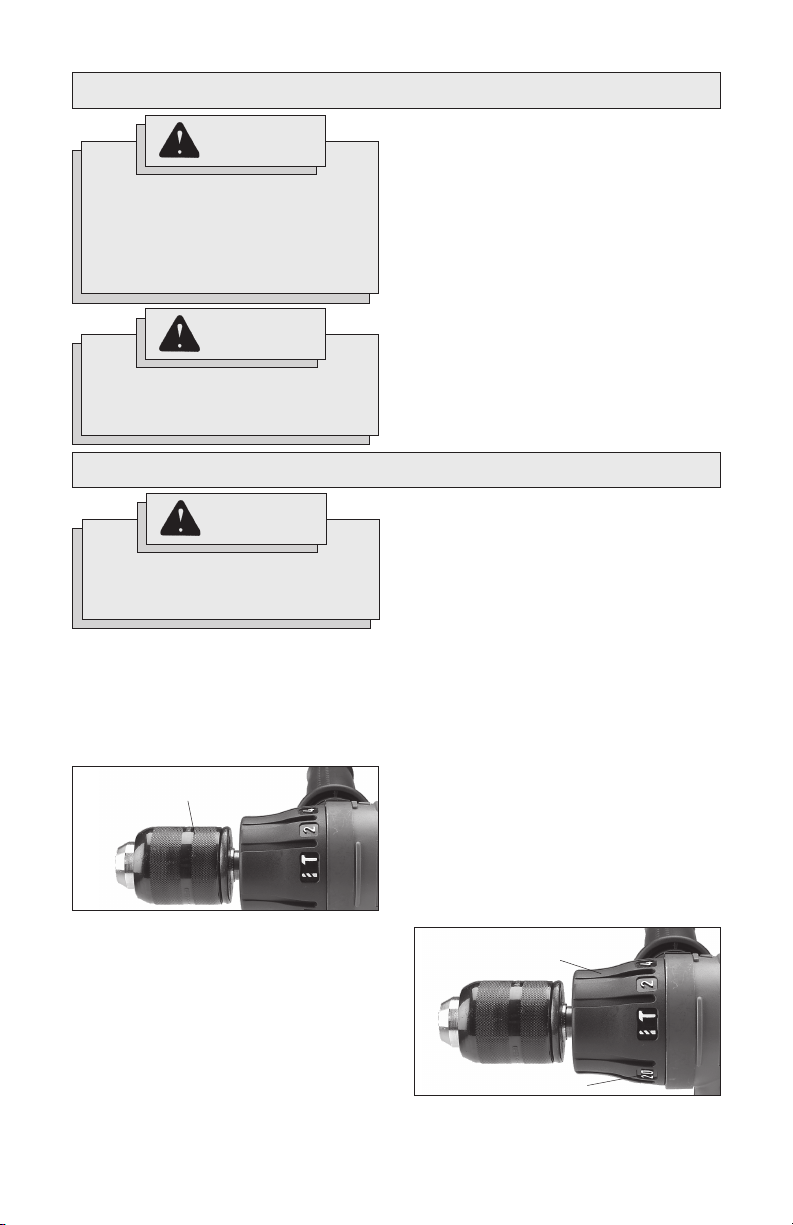
2. For optimum weight distribution and
balance.
Insert the battery pack from the back
by sliding the battery pack into the body
of the tool. Insert the battery pack until
the battery latches lock.
3. To remove the battery pack, press in
both battery latches and slide the bat-
tery pack off of the tool.
Fig. 1
Fig. 2
7
WARNING!
ASSEMBLY
Always lock trigger or remove
battery pack before changing or
removing accessories. Only use
accessories specifically
recommended for this tool.
Others may be hazardous.
WARNING!
To reduce the risk of injury, always
use a side handle when using this
tool. Always brace or hold securely.
Installing the Side Handle
1. To install the side handle, loosen the
side handle grip until the ring is large
enough to slide over the torque selec-
tor collar. The raised rib on the side
handle ring fits inside the groove
around the tool. Rotate the handle to
the desired position and tighten the
side handle until it is secure.
2. To remove the side handle, loosen
the side handle grip until the ring is
large enough to slide off the tool.
OPERATION
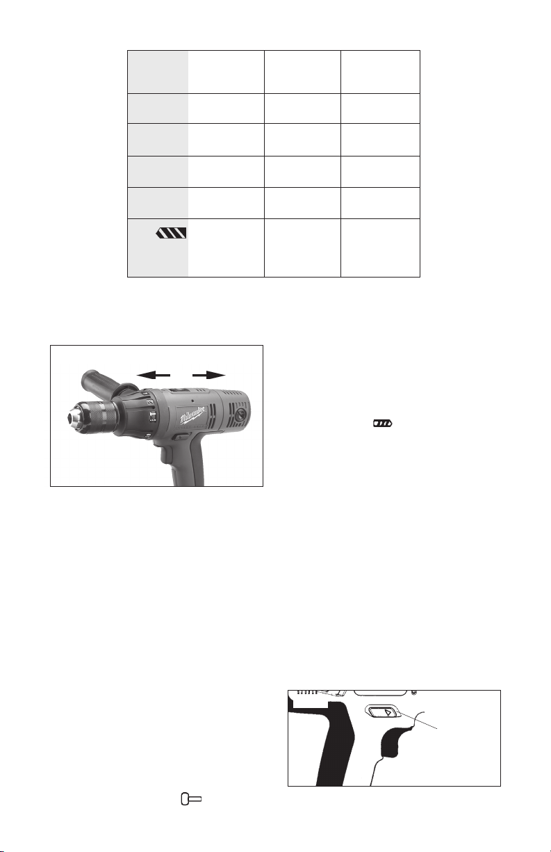
Using Keyless Chucks (Fig. 3)
Your cordless tool is equipped with a spindle
lock. The chuck can be tightened with one
hand, creating higher grip strengths on the bit.
Always remove the battery pack or lock
the trigger before inserting or removing bits.
1. To open the chuck jaws, turn the sleeve
in the counterclockwise direction.
When using drill bits, allow the bit to
strike the bottom of the chuck. Center
the bit in the chuck jaws and lift it about
1/16" off of the bottom.
When using screwdriver bits, insert
the bit far enough for the chuck jaws
to grip the hex of the bit.
2. To close the chuck jaws, turn the
sleeve in the clockwise direction. The
bit is secure when the chuck makes a
WARNING!
To reduce the risk of injury, wear
safety goggles or glasses with
side shields.
ratcheting sound and the sleeve can
not be rotated any further.
3. To remove the bit, turn the sleeve in
the counterclockwise direction.
NOTE: A ratcheting sound may be heard
when the chuck is opened or closed. This
noise is part of the locking feature, and
does not indicate a problem with the chuck's
operation.
The torque specifications shown here are
approximate values obtained with a fully
charged battery pack.
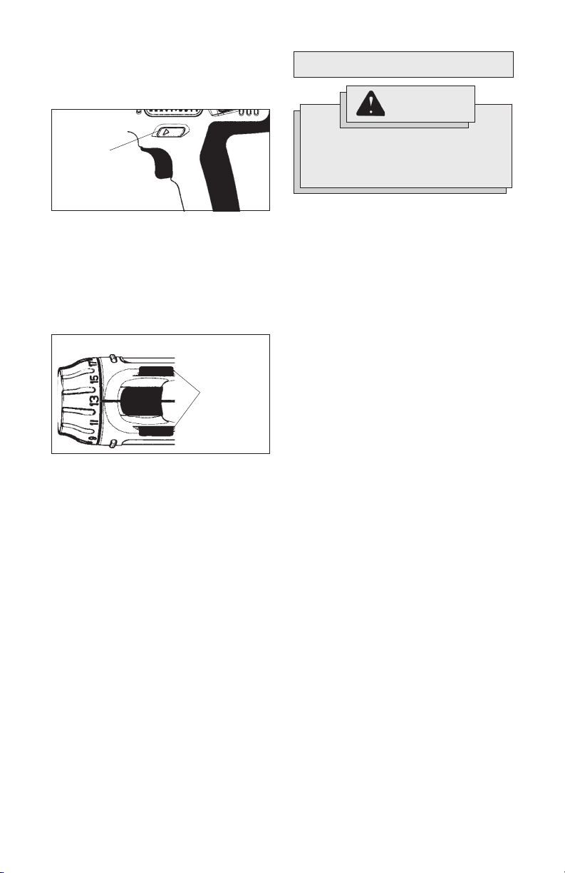
Using Clutch (Fig. 4)
This tool has an adjustable clutch for driv-
ing different types of screws into differ-
ent materials. When properly adjusted, the
clutch will slip at a preset torque to pre-
vent driving the screw too deep and to
prevent damage to the screw or tool.
To adjust the clutch, turn the torque selec-
tor collar to one of the twenty positions
shown on the collar. The number must line
up with the arrow on top of the tool.
Fig. 3
Sleeve
Fig. 4
Torque selector
collar
Position numbers
8
Selecting Speed (Fig. 5)
NOTE: Because the above settings are only a guide, use a
piece of scrap material to test the different clutch posi-
tions before driving screws into the workpiece.
Positions
1 - 5
6 - 10
11 - 15
16 - 20
Drill
Low
High
0 - 17 in. lbs.
21 - 38 in. lbs.
42 - 60 in. lbs.
65 - 85 in. lbs.
460 in. lbs.
160 in. lbs.
0614-20 &
0616-20
0 - 17 in. lbs.
21 - 38 in. lbs.
42 - 60 in. lbs.
65 - 85 in. lbs.
350 in. lbs
120 in. lbs.
Torque
0613-20
Torque
0 - 17 in. lbs.
21 - 38 in. lbs.
42 - 60 in. lbs.
65 - 85 in. lbs.
495 in. lbs.
175 in. lbs.
0622-20 &
0624-20
Torque
Fig. 5
Low
High
line with the arrow. Apply pressure to
the bit to engage the hammering
mechanism.
2. To use the drilling only mode, ro-
tate the torque selector collar until the
drill symbol appears in line with
the arrow.
NOTE: When using carbide bits, do not use
water to settle dust. Do not attempt to drill
through steel reinforcing rods. Both ac-
tions will damage the carbide bits.
The speed selector is on top of the motor
housing. Allow the tool to come to a com-
plete stop before changing speeds. See
“Applications” for recommended speeds
under various conditions.
1. For Low speed (up to 500 RPM), push
the speed selector forward.
2. For High speed (up to 1700 RPM), push
the speed selector back.
Selecting Hammer or Drill Action
(Cat. No. 0613-20, 0614-20, and 0624-20 only)
MILWAUKEE
Hammer-Drills are designed
for two operating modes: drilling with ham-
mering action and drilling only. To set the
operating mode, rotate the torque selector
collar to the desired symbol. A drill or ham-
mer symbol will appear in line with the ar-
row to indicate operating mode.
1. To use the hammer-drilling mode,
rotate the torque selector collar until
the hammer symbol appears in
Using Control Switch (Fig. 6, 7 and 8)
The control switch may be set to three
positions: forward, reverse and lock. Due
to a lockout mechanism, the control switch
can only be adjusted when the ON/OFF
switch is not depressed. Always allow the
motor to come to a complete stop before
using the control switch.
For forward (clockwise) rotation, push in
the control switch from the right side of the
tool (Fig. 6). Check the direction of
rotation before use.
Push in
for forward
Fig. 6
9
Starting, Stopping & Controlling
Speed
1. To start the tool, pull the trigger.
2. To stop the tool, release the trigger
and an electric brake stops the tool
instantly.
All models feature variable speed control.
To vary the speed, simply increase or de-
crease pressure on the trigger. The further
the trigger is pulled, the greater the speed.
Drilling
Set the torque selector collar to the drill
position
Place the bit on the work surface and ap-
ply firm pressure before starting. Too much
pressure will slow the bit and reduce drill-
ing efficiency. Too little pressure will cause
the bit to slide over the work area and dull
the point of the bit.
If the tool begins to stall, reduce pressure
slightly to allow the bit to regain speed. If
the bit binds, reverse the motor to free the
bit from the workpiece.
APPLICATIONS
Drilling in Wood, Composition
Materials and Plastic
When drilling in wood, composition materi-
als and plastic, start the drill slowly, gradu-
ally increasing speed as you drill. When
drilling into wood, use wood augers or
twist drill bits. Always use sharp bits.
When using twist drill bits, pull the bit out of
the hole frequently to clear chips from the
bit flutes. To reduce the chance of splin-
tering, back work with a piece of scrap
wood. Select low speeds for plastics with
a low melting point.
Drilling in Metal
When drilling in metal, use high speed steel
twist drills or hole saws. Use a center
punch to start the hole. Lubricate drill bits
with cutting oil when drilling in iron or steel.
Use a coolant when drilling in nonferrous
metals such as copper, brass or aluminum.
Back the material to prevent binding and
distortion on breakthrough.
Drilling in Masonry
When drilling in masonry, select the
hammer-drill operating mode
(Cat. No. 0613-20, 0614-20, and 0624-20
only). Use high speed carbide-tipped bits.
Drilling soft masonry materials such as cin-
der block requires little pressure. Hard ma-
terials like concrete require more pressure.
A smooth, even flow of dust indicates the
proper drilling rate. Do not let the bit spin in
the hole without cutting. Do not use water
to settle dust or to cool bit. Both actions
will damage the carbide.
WARNING!
To reduce the risk of electric
shock, check work area for hidden
pipes and wires before drilling or
driving screws.
For reverse (counterclockwise) rotation,
push in the control switch from the left
side of the tool (Fig. 7). Check direction
of rotation before use.
Fig. 7
To lock the trigger, push the control switch
to the center position (Fig. 8). The trigger
will not work while the control switch is in
the center locked position. Always lock the
trigger or remove the battery pack before
performing maintenance, changing acces-
sories, storing the tool and any time the
tool is not in use.
Push in
for reverse
Fig. 8
Push to
center
position to
lock trigger
10
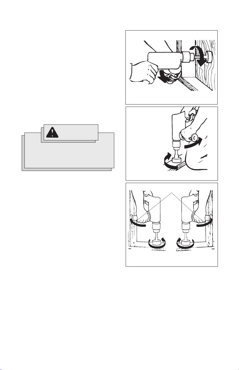
Bit Binding
A high rotational force occurs when a bit
binds. If the bit binds, the tool will be forced
in the opposite direction of the bit rotation.
Bits may bind if they are misaligned or when
they are breaking through a hole. Wood
boring bits can also bind if they run into
nails or knots. Be prepared for bit binding
situations.
WARNING!
High rotational force. To reduce
the risk of injury, always hold or
brace securely. Always use side
handle on tools.
Fig. 9
Forward rotation
Reaction
Bracing against the floor
To reduce the chance of bit binding:
• Use sharp bits. Sharp bits are less
likely to bind when drilling.
• Use the proper bit for the job. There
are bits that are designed for specific
purposes.
• Use caution when drilling pitchy,
knotty, wet or warped material or
when drilling in material that may con-
tain nails.
Fig. 11
Bracing against a stud
Reverse rotation
Reaction
Forward rotation
Fig. 10
Forward
rotation
Bracing against your leg
Reaction
Typical Bracing Methods
Driving Screws and Nut Running
Drill a pilot hole when driving screws into
thick or hard materials. Set the torque se-
lector collar to the proper position and set
the speed to low. Use the proper style and
size screwdriver bit for the type of screw
you are using.
With the screwdriver bit in the screw, place
the tip of the screw on the workpiece and
apply firm pressure before pulling the trig-
ger. Screws can be removed by reversing
the motor.
Overloading
Continuous overloading may cause per-
manent damage to tool or battery pack.
11
MAINTENANCE
WARNING!
To reduce the risk of injury,
always unplug the charger and
remove the battery pack from
the charger or tool before
performing any maintenance.
Never disassemble the tool,
battery pack or charger. Contact
a
MILWAUKEE
service facility for
ALL repairs.
Keep your tool, battery pack and charger
in good repair by adopting a regular main-
tenance program. After six months to one
year, depending on use, return the
tool, battery pack and charger to a
MILWAUKEE
service facility for:
• Lubrication
• Mechanical inspection and cleaning
(gears, spindles, bearings, housing,
etc.)
• Brush inspection and replacement
• Electrical inspection (battery pack,
charger, motor)
• Testing to assure proper mechanical
and electrical operation
Maintaining Tool
If the tool does not start or operate at full
power with a fully charged battery pack,
clean the contacts on the battery pack. If
the tool still does not work properly, return
the tool, charger and battery pack, to a
MILWAUKEE
service facility for repairs.
Maintaining Battery Pack
MILWAUKEE
battery packs will operate
for many years and/or hundreds of cycles
when they are maintained and used ac-
cording to these instructions.
A battery pack that is stored for six months
without being used will discharge itself.
Batteries discharge at a rate of about 1%
per day. Charge the battery every six
months even if it is unused to maximize
battery life. Do not tape the trigger in the
“ON” position and leave the tool unattended
as this may discharge the battery to a point
where it will no longer be able to recharge.
Use a
MILWAUKEE
battery pack only until
it no longer performs with the power and
torque needed for your application.
Store your battery pack in a cool, dry place.
Do not store it where the temperature may
exceed 120°F (50°C) such as a vehicle or
metal building during the summer. High tem-
peratures will overheat the battery pack,
reducing battery life. If it is stored for sev-
eral months, the battery pack will gradu-
ally lose its charge. One to three cycles of
charging and discharging through normal
use will restore the capacity of the battery
pack. During the life of the battery pack the
operating time between charges becomes
shorter. If the operating time becomes ex-
tremely short after a proper charge, the
usable life of the battery pack has been
reached and it should be replaced.
WARNING!
To reduce the risk of personal
injury and damage, never
immerse your tool, battery pack
or charger in liquid or allow a
liquid to flow inside them.
Cleaning
Clean dust and debris from charger and
tool vents. Keep tool handles clean, dry
and free of oil or grease. Use only mild
soap and a damp cloth to clean the tool,
battery pack and charger since certain
cleaning agents and solvents are harmful
to plastics and other insulated parts. Some
of these include gasoline, turpentine, lac-
quer thinner, paint thinner, clhlorinated
cleaning solvents, ammonia and household
detergents containing ammonia. Never use
flammable or combustible solvents around
tools.

12
WARNING!
To reduce the risk of explosion,
never burn a battery pack even if
it is damaged, dead or
completely discharged.
RBRC Battery Recycling Seals
The RBRC™ Battery Recycling Seals (see
"Symbology") on your tool battery packs in-
dicate that
MILWAUKEE
has arranged for
the recycling of that battery pack with the
Rechargeable Battery Recycling Corporation
(RBRC). At the end of your battery pack's
useful life, return the battery pack to a
MILWAUKEE
Branch Office/Service Center
or the participating retailer nearest you. For
more information, visit the RBRC web site at
www.rbrc.org.
Disposing of Nickel-Cadmium Battery
Packs
Nickel-Cadmium battery packs are recy-
clable. Under various state and local laws,
it may be illegal to dispose of this batter
into the municipal waste stream. Dispose
of your battery pack according to federal,
state and local regulations.
Repairs
For repairs, return the tool, battery pack and
charger to the nearest service center listed
on the back cover of this operator's manual.
Battery Pack Warranty
Battery packs for cordless tools are
warranted for one year from the date of
purchase.
FIVE YEAR TOOL
LIMITED WARRANTY
Every
MILWAUKEE
tool is tested before
leaving the factory and is warranted to be
free from defects in material and work-
manship.
MILWAUKEE
will repair or re-
place (at
MILWAUKEE
’s discretion), with-
out charge, any tool (including battery
chargers) which examination proves to be
defective in material or workmanship from
five (5) years after the date of purchase.
Return the tool and a copy of the purchase
receipt or other proof of purchase to a
MILWAUKEE
Factory Service/Sales Sup-
port Branch location or
MILWAUKEE
Au-
thorized Service Station, freight prepaid
and insured. This warranty does not cover
damage from repairs made or attempted
by other than
MILWAUKEE
authorized per-
sonnel, abuse, normal wear and tear, lack
of maintenance, or accidents.
Battery Packs, Flashlights, and Radios are
warranted for one (1) year from the date
of purchase.
THE REPAIR AND REPLACEMENT REMEDIES
DESCRIBED HEREIN ARE EXCLUSIVE. IN NO
EVENT SHALL
MILWAUKEE
BE LIABLE
FOR ANY INCIDENTAL, SPECIAL, OR CON-
SEQUENTIAL DAMAGES, INCLUDING LOSS
OF PROFITS.
THIS WARRANTY IS EXCLUSIVE AND IN
LIEU OF ALL OTHER WARRANTIES, OR
CONDITIONS, WRITTEN OR ORAL, EX-
PRESSED OR IMPLIED FOR
MERCHANTABLILITY OR FITNESS FOR
PARTICULAR USE OR PURPOSE.
This warranty gives you specific legal
rights. You may also have other rights that
vary from state to state and province to
province. In those states that do not allow
the exclusion of implied warranties or limi-
tation of incidental or consequential dam-
ages, the above limitations or exclusions
may not apply to you. This warranty ap-
plies to the United States, Canada, and
Mexico only.
 Loading...