


G800
Table of contents
 Loading...
TECHNICAL INFORMATION
G600 & G800 Electronic Dishwashers
© 2003 Miele

Technical Information
G600 & G800 Electronic Dishwashers
G600 & G800 Electronic Dishwashers – Table of Contents
1.0 Construction Design…………………………………………………………….8
1.1 Appliance Overview................................................ ……………………9
1.1.1 Appliance Overview – Typical Integrated Model....................... 9
1.1.2 Unit Overview – Typical Fully Integrated (VI) Model............... 10
1.2 Controls Overview .............................................................................11
1.3 Types of Dishwashers ........................................................................13
1.4 Technical Data....................................................................................14
1.4.1 Dishwasher Width................................................................... 14
1.4.2 Dishwasher Height ................................................................. 14
1.4.3 Summary of Dimensions......................................................... 15
1.4.4 Electrical Information.............................................................. 15
1.4.5 Hard Wire Electrical Connection............................................. 16
1.4.6 Plumbing Connection.............................................................. 16
1.4.6.1 Intake Connection..................................................... 16
1.4.6.2 Drain Connection...................................................... 16
1.5 Data Tag.............................................................................................17
1.6 Layout of Components........................................................................18
1.6.1 Novotronic and Touchtronic Series......................................... 18
1.6.2 Incognito Series...................................................................... 19
2.0 Installation (Refer to the Appliance Installation Manual)………………. 20
3.0 Commission and Operation………………………………………………….21
3.1 Door Handle and Door Lock (Novotronic & Touchtronic Series).........21
3.2 Closing the Dishwasher Door.............................................................21
3.3 Child Safety Lock................................................................................21
3.4 Water Softener ...................................................................................22
3.5 General Operation – Novotronic Series..............................................23
3.6 General Operation – Touchtronic Series ............................................23
3.7 General Operation – Incognito Series.................................................23
4.0 Description of Function……………………………………………………….24
4.1 Cabinet Construction..........................................................................24
4.2 Fan Assembly (Turbothermic Fan Equipped Models).........................24
4.2.1 PTC Release Element............................................................ 24
4.3 Combination Dispenser ......................................................................25
4.3.1 Construction ........................................................................... 25
4.3.2 Dispensing...............................................................................26
4.4 Heaters...............................................................................................27
4.4.1 Wash Cavity Heating Element............................................... 27
4.4.2 Flow Through Heater:............................................................ 28
2

G600 & G800 Electronic Dishwashers
Technical Information
G600 & G800 Electronic Dishwashers – Table of Contents (continued)
4.4.2.1 Flow Through Heater Electrical Data........................ 28
4.5 Heater Circuit - Operation..................................................................29
4.6 Pulsed Heating - Operation................................................................30
4.7 Temperature Protection.....................................................................30
4.8 Static Drying ......................................................................................30
4.9 Spray Arms........................................................................................31
4.9.1 Spray Arms - Rotation Data.................................................. 31
4.10 Filter Assembly..................................................................................31
4.11 Water Intake – Technical Data ..........................................................32
4.12 WaterProof System ...........................................................................33
4.13 Flowmeter - Operation.......................................................................36
4.14 Water Intake......................................................................................37
4.15 Water Mixing......................................................................................38
4.15.1 Water Mixing - External Flowmeter...................................... 38
4.15.2 Water Mixing - Integrated Flowmeter................................... 39
4.15.3 Solenoid Valve - Operating (Plus Models Only).................. 41
4.16 Electronic Controlled Water Hardness...............................................42
4.17 Water Softener ..................................................................................43
4.17.1 Reactivation......................................................................... 44
4.17.2 Reactivation Cycles ............................................................. 45
4.18 Condenser Drying (UKT)...................................................................46
4.18.1 Operation............................................................................. 46
4.18.2 Technical Data..................................................................... 46
4.18.3 Control Valve ....................................................................... 48
4.19 Drain Pump, Circulation Pump ..........................................................49
4.20 Level Switch – Heater (Heater Pressure Switch)...............................49
4.21 Level Switch (Intake Overflow)..........................................................51
4.22 Temperature Sensor..........................................................................52
4.23 Top Solo Valve..................................................................................53
4.24 Turbidity Sensor (ECO Sensor).........................................................54
4.25 Electronic Unit - Power Outputs.........................................................55
4.25.1 Programming After Replacing the Electronic ....................... 56
4.25.2 Electronic Modes ................................................................. 56
5.0 Service and Maintenance……………………………………………………..57
5.1 Locking Plate - Adjustment................................................................57
5.2 Cabinet Seal - Replacement..............................................................57
5.3 Side Panel - Removal........................................................................58
5.4 Spring Bracket - Replacement ..........................................................59
5.5 Cover Plate - Removal .....................................................................60
5.6 Connecting Strip - Removal...............................................................61
5.7 Basket Support Rollers – Replacement.............................................62
5.8 Combination Dispenser - Removal....................................................64
5.9 Turbothermic Fan - Removal.............................................................65
3

Technical Information
G600 & G800 Electronic Dishwashers
G600 & G800 Electronic Dishwashers – Table of Contents (continued)
5.10 Door Panel (Outer and Inner) - Removal...........................................66
5.11 Cable Holder - Removal ...................................................................67
5.12 Lock / Handle Assembly - Removal...................................................68
5.13 Door Hinge - Removal.......................................................................69
5.14 Door Tension - Adjustment................................................................70
5.15 Top Spray Arm - Removal.................................................................71
5.16 Middle Spray Arm - Removal.............................................................71
5.17 Bottom Spray Arm - Removal............................................................71
5.18 Top Spray Arm Feed Pipe - Removal................................................71
5.19 Middle Spray Arm Cover - Removal..................................................72
5.20 Middle Spray Arm Feed Pipe - Removal ...........................................72
5.21 Flow-Through Heater - Removal .......................................................73
5.22 Temperature Limiter - Replacement.................................................. 74
5.23 Microfine Filter – Exchange...............................................................75
5.24 WaterProof System (WPS) - Removal...............................................76
5.25 WaterProof System (WPS) Restrictor - Exchange.............................77
5.26 Water Inlet (Diverter) - Removal........................................................78
5.27 Water Softener – Operational Check.................................................79
5.28 Water Softener Assembly- Removal..................................................80
5.29 Drip Tray - Removal ..........................................................................80
5.30 Float Switch Housing - Removal........................................................80
5.31 Float Switch – Removal....................................................................81
5.32 Steam Condenser - Removal ............................................................82
5.33 Control Valve - Removal...................................................................83
5.34 Temperature Sensor (NTC) - Removal ............................................ 83
5.35 Circulation Pump (M6) - Removal...................................................... 84
5.36 Circulation Pump - Partition & Impeller Replacement........................85
5.37 Circulation Pump Housing - Exchange............................................ 86
5.38 Circulation Pump – Release with Tool...............................................86
5.39 Heater Level Switch – Removal.........................................................88
5.40 Drain Pump – Removal .....................................................................89
5.41 Top Solo Valve - Removal.................................................................90
5.42 Overflow Level Switch - Removal......................................................91
5.43 Sump - Removal................................................................................92
5.44 Turbidity Sensor - Calibration............................................................93
5.45 Turbidity Sensor - Removal...............................................................93
5.46 Fully Integrated (Vi) Control Panel - Removal ...................................94
5.47 Novotronic & Touchtronic Control Panel – Removal..........................95
5.48 Fixing Bracket – Removal..................................................................96
5.49 Heating Relay & Power Relay – Removal .........................................97
4

G600 & G800 Electronic Dishwashers
Technical Information
G600 & G800 Electronic Dishwashers – Table of Contents (continued)
6.0 Fault Diagnosis……………………………………………………………….....98
6.1 General Information...........................................................................98
6.2 Programming and Service Mode - Features......................................98
6.2.1 Water Hardness Programming............................................ 98
6.2.2 Drying Options (As Applicable)........................................... 98
6.2.3 Water Intake Duration......................................................... 98
6.2.4 Buzzer (As Applicable)........................................................ 99
6.2.5 Fault Code (Retrieval)......................................................... 99
6.2.6 Increase Temperature......................................................... 99
6.2.7 With OR Without Water Softener........................................ 99
6.2.8 2nd Interim Rinse................................................................ 99
6.2.9 Width of Unit ..................................................................... 100
6.2.10 Flowmeter Count .............................................................. 100
6.2.11 Operating Hours ............................................................... 100
6.3 Programming / Service Modes – Access……………………………...100
6.4 Timing Charts – General Information ................................................101
6.5 Wiring Diagrams – General Information...........................................105
6.6 Timing Charts & Wire Diagrams ......................................................105
6.7 Fault Repair..................................................................................... 106
5

Technical Information
G600 & G800 Electronic Dishwashers
G600 &G800 Electronic Dishwashers – List of Figures
1-1: Appliance Overview - Typical Integrated Model...................................9
1-2: Appliance Overview – Typical Fully Integrated (Vi) Model.................10
1-3: Pre-Finished Dishwasher...................................................................13
1-4: Integrated Dishwasher.......................................................................13
1-5: Fully Integrated..................................................................................13
1-6: Dishwasher Widths ............................................................................14
1-7: Dishwasher Heights...........................................................................14
1-8: Data Tag Locations and Information..................................................17
1-9: Component Overview – Novotronic & Touchtronic Series .................18
1-10: Component Overview – Incognito (Vi) Series ....................................19
4-1: Dispenser Assembly ..........................................................................25
4-2: Cavity Style Heater Element..............................................................27
4-4: Heater Circuit.....................................................................................29
4-5: Filter Assembly ..................................................................................31
4-6: WaterProof System Connection.........................................................33
4-7: Water Intake Circuit............................................................................35
4-8: Flowmeter Assembly Components (External Flowmeter Shown) ......36
4-9: Water Intake System Equipped With Integrated Flowmeter...............37
4-10: Water Hardness Selector...................................................................38
4-11: Water Path with Integrated Flowmeter...............................................39
4-12: Water Inlet Mixer................................................................................40
4-13: Water Hardness Mixer Solenoid ........................................................41
4-14: Water Softener...................................................................................43
4-15: Components for the Condenser Drying System.................................47
4-16: Control Valve .....................................................................................48
4-17: Heater Pressure Switch – Contact Positions and Current Paths........50
4-18: Water Intake / Level Switch Circuit.....................................................51
4-19: Circulation Pump & Top Solo Valve...................................................53
4-20: Turbidity Sensor (ECO Sensor) .........................................................54
5-1: Locking Plate .....................................................................................57
5-2: Seal Fitting Plan.................................................................................57
5-3: Side Panels and Cabinet....................................................................58
5-4: Side View, Door with Bracket............................................................. 59
5-5: Cover Plate........................................................................................60
5-6: Plinth area with Connecting Strip.......................................................61
5-7: Basket Guide .....................................................................................62
5-8: Bolt and Retaining Clip.......................................................................62
5-9: Basket Guide Stopper........................................................................63
5-10: Stopper removal.................................................................................63
6

G600 & G800 Electronic Dishwashers
Technical Information
G600 &G800 Electronic Dishwashers – List of Figures (continued)
5-11: Exterior view of the Inner Door Panel.................................................64
5-12: Fan Removal...................................................................................... 65
5-13: Inner Door Panel Removal.................................................................66
5-14: Cable Holder Removal.......................................................................67
5-15: Lock Removal....................................................................................68
5-16: Hinge Removal ..................................................................................69
5-17: Door Tension Adjustment Screw........................................................70
5-18: Middle Spray Arm Cover Removal.....................................................72
5-19: Dishwasher with Flow-Through Heater..............................................73
5-20: Flow-Through Heater with Seal..........................................................74
5-21: Microfine Filter – Replacement ..........................................................75
5-22: Pressing and Locking the Filter Assembly. ........................................76
5-23: Tilting the Flow Restrictor...................................................................77
5-24: Removing the Flow Restrictor............................................................77
5-25: Water Inlet - Removal ........................................................................78
5-26: Float Switch Housing .........................................................................81
5-27: Steam Condenser Components......................................................... 82
5-28: Circulation Pump – Removal..............................................................84
5-29: Components within the Circulation Pump ..........................................85
5-30: Placing the Circulation Pump Tool into ..............................................86
5-31: Engaging the tool prongs into the Circulation Pumps Impellers.........86
5-32: Turning the Circulation Pump Tool.....................................................87
5-33: Heater Level Switch and Circulation Pump........................................88
5-34: Drain Pump - Replacement................................................................89
5-35: Circulation Pump with Top Solo Valve attached. ...............................90
5-36: Releasing the Overflow Level Switch from the Connecting Strip .......91
5-37: Self Tensioning Sump Clamp.............................................................92
5-38: Sump Clamp without the self tensioning;...........................................92
5-39: Fully Integrated (Vi) Control Panel.....................................................94
5-40: Control Panel (Novotronic and Touchtronic Dishwashers).................95
5-41: Removing the Fixing Bracket.............................................................96
7

Technical Information
G600 & G800 Electronic Dishwashers
G600 &G800 Electronic Dishwashers – List of Tables
1-1: Summary of Dimensions......................................................................15
4-1: Detergent Quantity in Combination Dispensers...................................26
4-2: Rinse Aid Dispensing...........................................................................26
4-4: Flow Restrictor Data.............................................................................32
4-5: Water Inlet Mixer Data .........................................................................32
4-6: Reactivation Cycles Timing..................................................................45
4-7: Circulation and Drain Pump Data.........................................................49
4-8: NTC Sensor Resistance Values...........................................................52
4-9: Activation of Components....................................................................55
8
G600 & G800 Electronic Dishwashers
Technical Information
1.0 Construction and Design
1.1 Appliance Overview
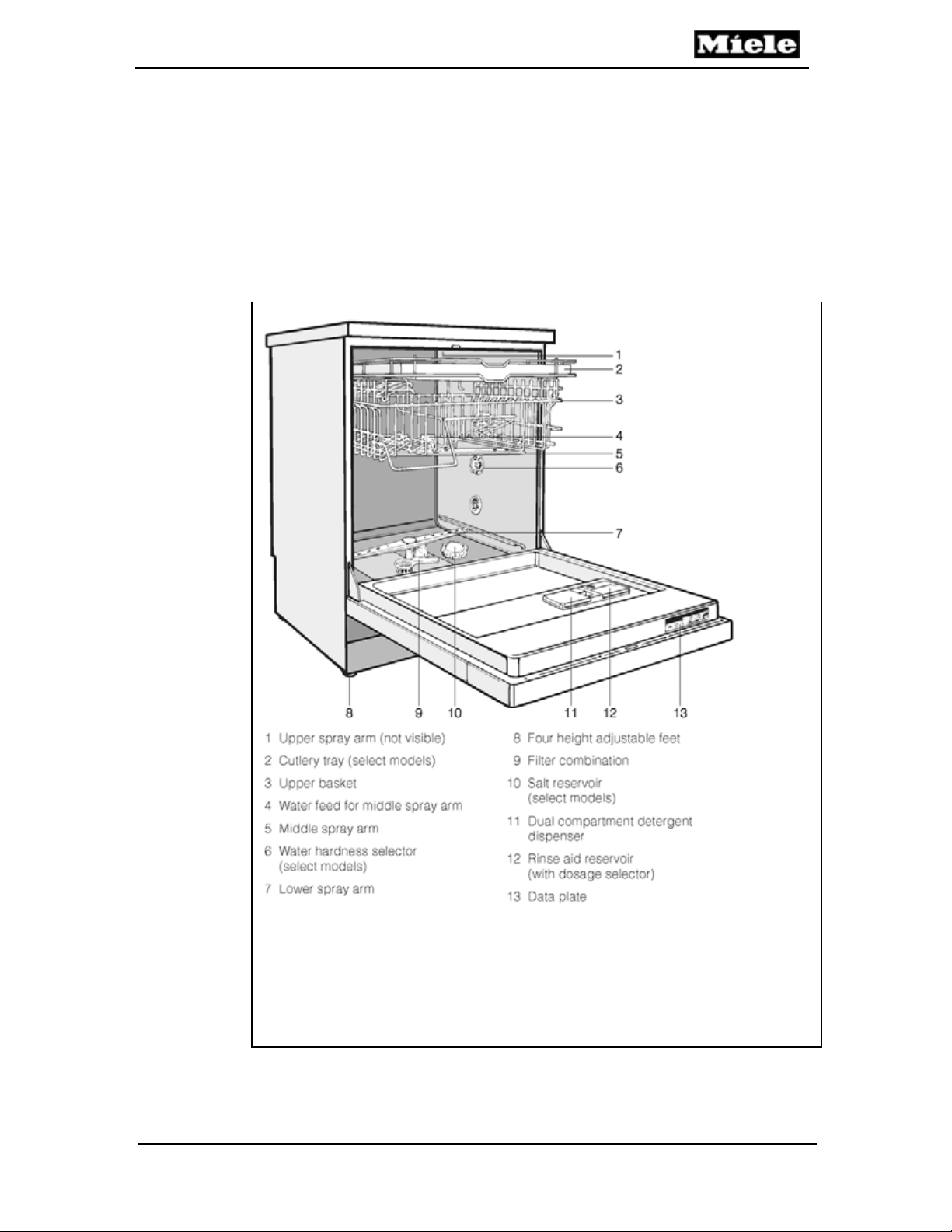
1.1.1 Appliance Overview – Typical Integrated Model
Figure 1-1: Appliance Overview - Typical Integrated Model
9

Technical Information
G600 & G800 Electronic Dishwashers
1.1.2 Unit Overview – Typical Fully Integrated Model
Figure 1-2: Appliance Overview – Typical Fully Integrated (Vi) Model
10

G600 & G800 Electronic Dishwashers
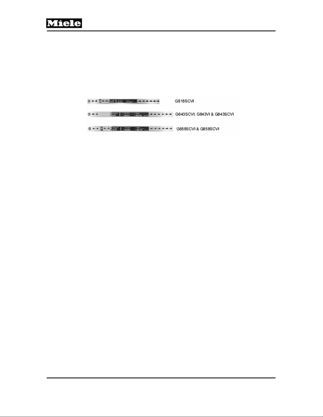
1.2 Controls Overview
Miele dishwashers are currently categorized into three (3) product
series, based on the type of controls.
Novotronic
Each Novotronic model dishwasher can be operated with a single
knob. Surface mounted design technology (SMD) allows Miele
Novotronic components to be extremely durable and reliable. These
controls are capable of performing hundreds of tasks which cannot be
handled by mechanical components.
Technical Information
Touchtronic
This new series of Miele dishwashers is operated by pushing a single
button -- no separate temperature or drying selections -- just turn the
machine on, pick a program and Miele does the rest. All models now
include a Pots and Pans program and a Water Management System,
designed to maximize cleaning results and optimize water and energy
conservation.
11
Technical Information
Incognito
The Incognito (fully integrated) series dishwashers have the program
controls located on the top edge of the door; and are accessed while
the door is open. Neither seen nor heard, the Miele Incognito Series
OCI (Optical Cycle Indicator) you to see the progress of the
dishwasher cycle by way of a red light, which is steady or flashing
depending on the status of the cycle.
G600 & G800 Electronic Dishwashers
12
G600 & G800 Electronic Dishwashers
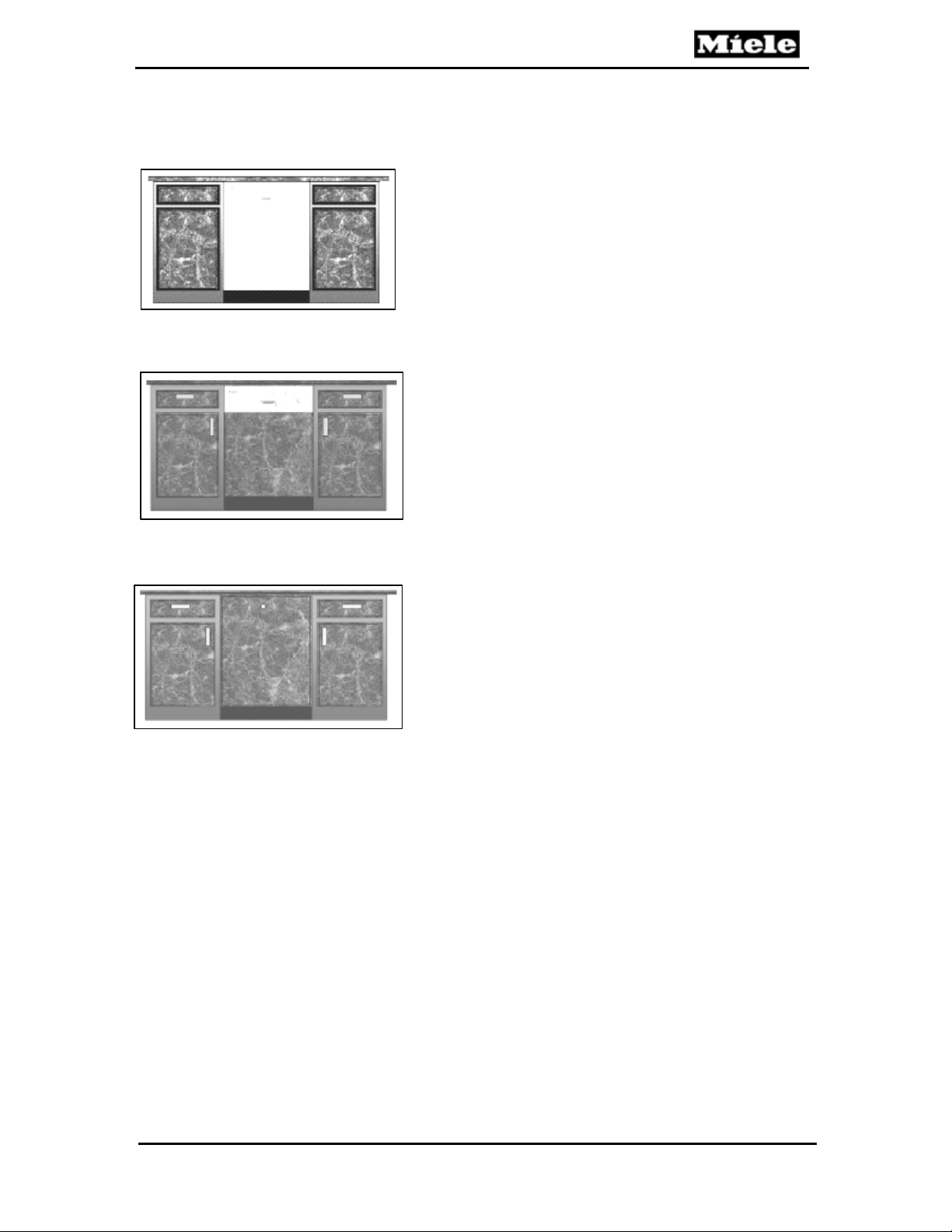
1.3 Types of Dishwashers
Pre-Finished: The pre-finished construction
consist of a pre-assembled door panel and control
panel; making it an ideal replacement unit.
Available in white, black or stainless steel.
Figure 1-3: Pre-Finished Dishwasher
Integrated: This type of dishwasher is shipped
with a separate control panel, and optional GDU
(door) panel. Every Integrated dishwasher ships
with a bracket for installing a custom cabinet
panel. The use of separate components allows for
a truly customized installation.
Figure1-4: Integrated Dishwasher
Fully Integrated: Fully Integrated (Incognito)
Dishwashers are designed to blend into the
surrounding cabinetry. The operator controls are
only available when door is opened. Each
dishwasher is shipped with a bracket for securing
a custom cabinet panel. An optional Miele
stainless steel SCVi panel is also available.
Figure 1-5: Fully Integrated
Technical Information
13
Technical Information
G600 & G800 Electronic Dishwashers
1.4 Technical Data
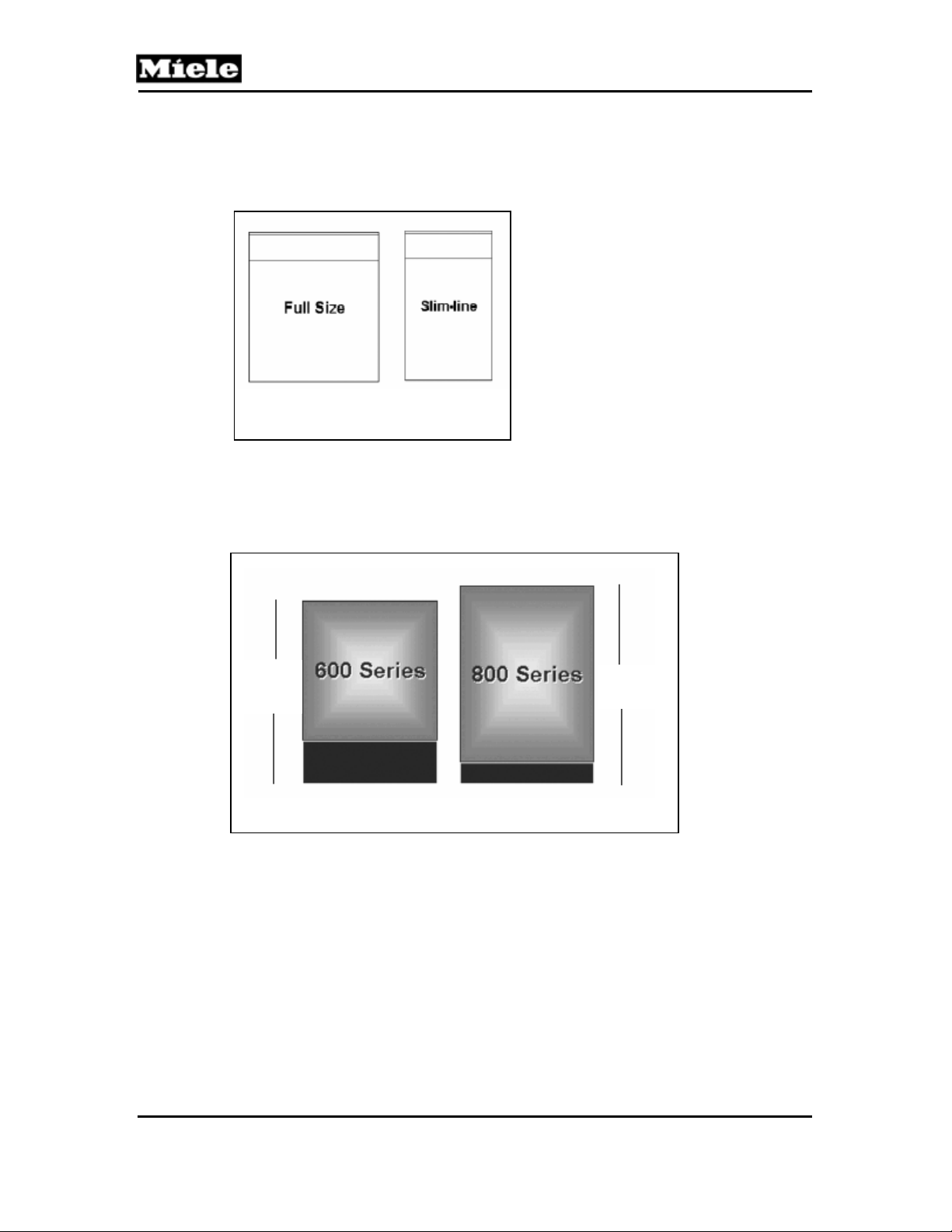
1.4.1 Dishwasher Width – Fullsize / Slimline
23 ½ in. 17 ½ in.
Figure 1-6: Dishwasher Widths
1.4.2 Dishwasher Height – 600 / 800 Series
32 1/4
to
34 7/8”
33 1/8
to 35”
Figure 1-7: Dishwasher Heights
14
G600 & G800 Electronic Dishwashers
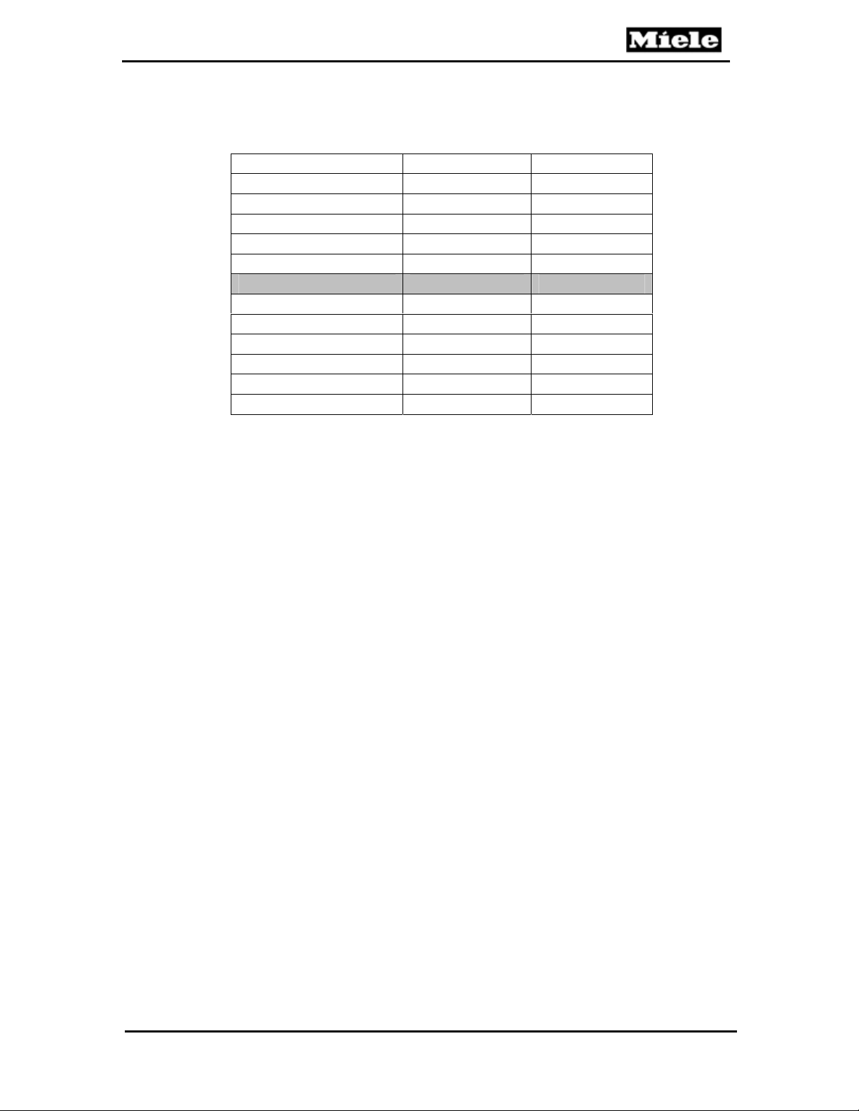
1.4.3 Summary of Dimensions
Technical Information
FULLSIZE G600 Series G800 Series
Height 32 ¼” - 34
Width of Machine 23
Width of Opening 23
1
/
” 23
2
5
/
” 23
8
7
/8” 33 1/
Depth 22 ½” 22 ½”
Depth w/ door open 45 ½” 47 ½”
SLIMLINE G600 Series G800 Series
Height 32 ¼” - 34
Width of Machine 17 ½” 17 ½”
Width of Opening 17 ¾ “ 17 ¾”
Depth 22 ½” 22 ½”
Depth w/ door open 45 ½” 47 ½”
7
/8” 331/
Table 1-1: Summary of Dimensions
1.4.4 Electrical Information
Power Requirements: 120 VAC, 60 Hz
Rated Load: 12.5 A / 1500 W (typical)
Circuit breaker: 15 AMPS
The appliance is equipped with a 4 ft power cord and molded
NEMA 515 plug; for connection to a NEMA 5-15R receptacle
(120VAC, 15 Amp, 3 prong, grounded outlet).
It is recommended that the power outlet for the appliance be
installed on the wall (within the cabinets), adjacent to under counter
space where the appliance is installed.
Ensure the cabinets contain no rough edges that could damage the
power cord or drain hose. If metal cabinets are used, ensure a
rubber grommet is installed around the opening.
Always exercise care when sliding the dishwasher in or out, to
prevent damaging the power cord and / or hoses.
”- 35”
8
1
/
”
2
5
/
”
8
” - 35”
8
15

Technical Information
G600 & G800 Electronic Dishwashers
1.4.5 Hard Wire Electrical Connection
Connections: L1 (Black) to L on terminal block, N (White) to N on
terminal block, GND To ground connector.
Hard wiring the dishwasher should only be done if required by
electrical code.
Do not cut the plug off the power supply cord / plug and connect it
directly to the house wiring under any circumstances. This voids the
warranty.
For hard wiring, the power cord must be removed from the
appliance by disconnecting the cord from the terminal box located
at the lower left front of the dishwasher, behind the Toekick and
Service Panel. Pass the permanent power supply cable through the
strain relief and secure it directly to the terminal box.
THIS APPLIANCE MUST BE GROUNDED
1.4.6 Plumbing Connection
1.4.6.1 Intake Connection
The appliance is equipped with a five (5) foot long Double WaterProof
System Intake Hose; equipped with a ¾ inch female hose connection;
for connection to a ¾ inch male hose thread water supply valve.
1.4.6.2 Drain Connection
The appliance is equipped with a five (5) foot long Drain Hose for
connection to a ¾ inch drain nipple.
16
G600 & G800 Electronic Dishwashers
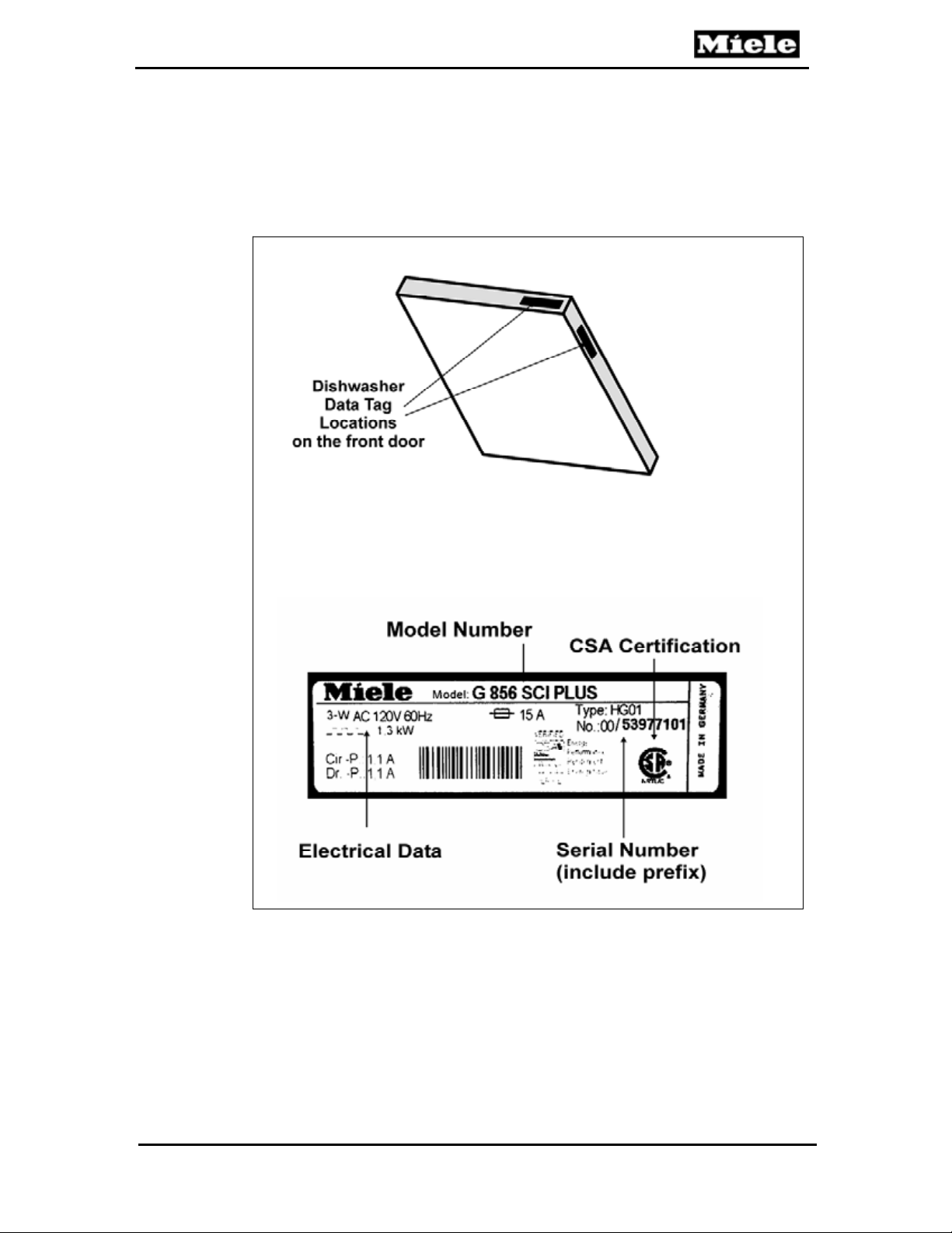
1.5 Data Tag
The Data Tag is located on the top edge of the door or on the right side
edge of the door (fully integrated models) - as shown.
Figure 1-8: Data Tag Locations and Information
Technical Information
ETL Certification –OR-
17
Technical Information
G600 & G800 Electronic Dishwashers
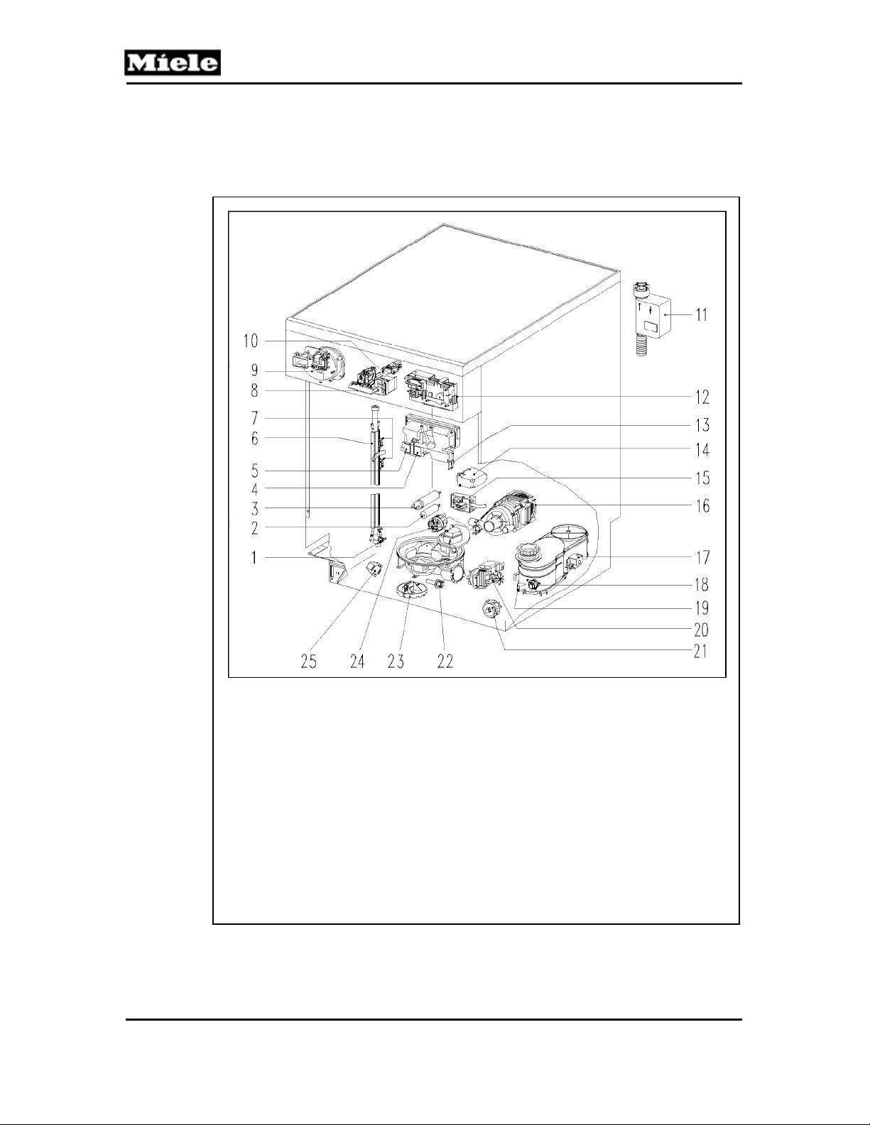
1.6 Layout of Components
1.6.1 Novotronic and Touchtronic Series
1 Temperature Limiter 90°C, 3F2. (before 8/99)
2 Interference Suppression Capacitor, Z2
3 Capacitor - Circulation Pump, C6
4 Rinse Aid Dispenser, Y50
5 Detergent Dispensert, Y51
6 Flow Through Heater, R1
7 Temperature Limiter 150°C, 1F2 and 2F2
8 Door Switch, S24
9 Fan M2 & PTC Release Element Y56
10 On / Off Switch, S2
11 WaterProof System (WPS), Y2
12 Electronic
13 Reed Switch - Rinse Aid, B8/1
14 Relay - Heating, 1K1/1
15 Terminal Block, X3/1
16 Circulation Pump, M6
17 Water Softener Valve, Y38/1
18 Flow Meter, B3/4
19 Reed Switch – Salt Float, B8/2
20 Drain Pump, M8
21 Level Switch - Overflow, B1/2
22 Temperature Sensor, R30
23 Float Switch, B8/3
24 Level Switch - Heating, B1/10
25 Transformer, T1
Figure 1-9: Component Overview – Novotronic & Touchtronic Series
18
G600 & G800 Electronic Dishwashers
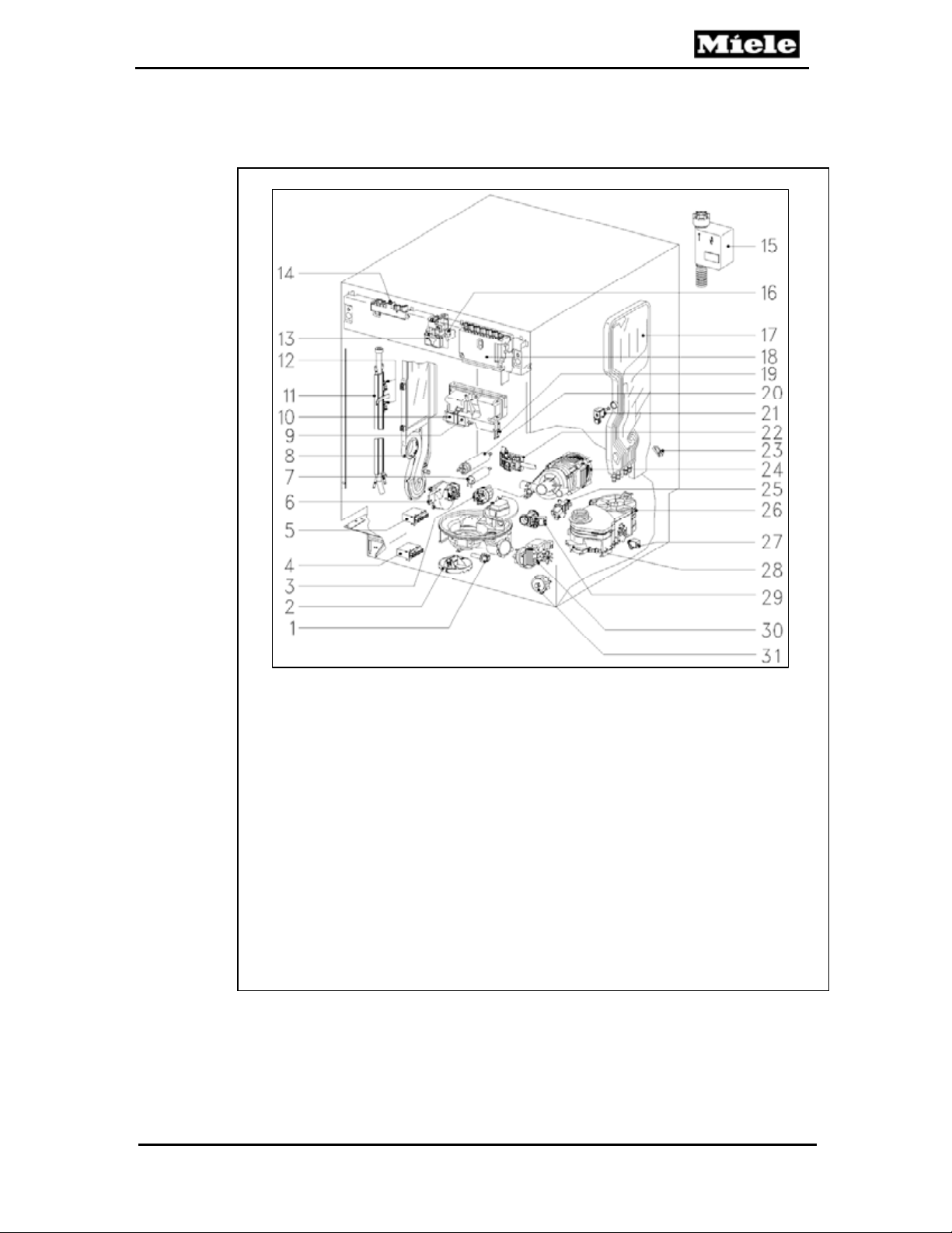
1.6.2 Incognito Series
Technical Information
Figure 1-10: Component Overview – Incognito (Vi) Series
1 Temperature Sensor, R30
2 Float Switch, B8/3
3 Level Switch - Heating, B1/10
4 Relay - Mains, 1K1/6
5 Relay - Heating, 1K1/1
6 Fan, M2
7 Interference Suppression Capacitor, Z2
8 Steam Condenser (not all models)
9 Rinse Aid Dispenser, Y50
10 Detergent Dispenser, Y51
11 Flow Through Heater, R1
12 Temperature Limiter, 1F2 and 2F2
13 Switch - Door Contact, S24
14 Electronic
15 WaterProof System (WPS), Y2
16 Door Switch, S5
17 Water Intake Mixer
18 Electronic
19 Reed Switch - Rinse Aid, B8/1
20 Capacitor - Circulation Pump, C6
21 Water Control Valve, Y5
22 Terminal Block, X3/1
23 Flow Meter, B3/4
24 Circulation Pump, M6
25 Condenser Control Valve, Y6 (if equip. w #8)
26 Water Softener (Resin Tank)
27 Water Softener Valve, Y38/1
28 Reed Switch - Reactivation Salt Indicator, B8/2
29 Circulation Valve, Y27
30 Drain Pump, M8
31 Level Switch - Overflow, B1/2
19
Technical Information
2.0 Installation
Refer to the Appliance Installation Manual.
G600 & G800 Electronic Dishwashers
20

G600 & G800 Electronic Dishwashers
3.0 Commission and Operation
3.1 Door Handle and Door Lock
(Novotronic and Touchtronic Series)
Press the release catch inside the Door Grip.
Note
If the door is opened during operation, the dishwasher will stop
running. Once the door is closed the program will restart.
Technical Information
3.2 Closing the Dishwasher Door
1. Push the baskets in.
2. Lift the door and push it closed until it locks into the closed
position.
3.3 Child Safety Lock
Horizontal:
the door is locked
Vertical:
the door can be opened
21

Technical Information
3.4 Water Softener
If your tap water hardness is above 8 grains per gallon (140 ppm), the
water should be softened.
A Water Hardness Test Strip is used to determine the water hardness.
If the Water Softener is needed:
The dishwasher must be programmed to “with Water Softener”
(ON).
The Water Softener reservoir is filled with softener salt.
The water hardness level is programmed into the dishwasher
electronic.
If the Water Softener is not needed:
The dishwasher must be programmed to “without Water
Softener” (OFF); however the hardness level is not programmed
into the electronic
Salt is not needed and should not be installed.
G600 & G800 Electronic Dishwashers
Water Softener Salt
Only use water softener salt specially formulated for dishwashers.
Other salts may contain insoluble additives that impair the Water
Softener. The proper salt can be purchased from the Miele Technical
Service Department.
To add salt:
1. Remove the Lower Basket.
2. Unscrew and remove the Salt Reservoir Cap located on the
3. If this is the first time salt is installed; add 2 quarts water.
4. Place a funnel over the Salt Reservoir. Carefully fill with salt.
5. Clean any excess salt from the threads of the reservoir
6. Run the "Rinse & Hold" program to remove any traces of salt
floor of the Wash Cabinet.
Note
The Salt Reservoir holds approximately 4.5 lbs (2 kg) of
salt.
opening; and screw the cap on firmly.
from inside the Wash Cabinet.
22

G600 & G800 Electronic Dishwashers
Technical Information
3.5 General Operation – Novotronic Series
1. Make sure the Spray Arms are not blocked.
2. Close the door.
3. Turn on the dishwasher. The "Start" Indicator will flash.
4. Select a wash program by turning the Program Selector to the left
or right.
5. Press the "Start" button.
3.6 General Operation – Touchtronic Series
1. Make sure the Spray Arms are not blocked.
2. Close the door.
3. Turn on the dishwasher. The "Start/Stop" Indicator will flash
and a Program Indicator will light.
4. Select a wash program using the Program Selection Buttons. The
Selected Program Indicator will light.
5. Select "Top Solo" if desired.
6. Press the "Start/Stop" button.
3.7 General Operation – Incognito Series
1. Open the door.
2. Make sure the Spray Arms are not blocked.
3. Turn on the dishwasher using the "On" button.
4. Select a wash program using the Program Selection Buttons.
The Selected Program Indicator will light.
5. Close the door. The Optic Indicator illuminates and the program
begins.
Note
For specific program details and further information on operating the
dishwasher refer to the model specific Operating Manual.
23

Technical Information
G600 & G800 Electronic Dishwashers
4.0 Description of Function
4.1 Cabinet Construction
The inner cabinet is constructed of stainless steel (1.4301) welded
onto four (4) vertical U-section sub-frames. The cabinet is sound and
heat-insulated with bitumen and/or mineral wool matting.
4.2
Fan Assembly
(Units equipped with Turbothermic Fan)
The fan assembly consists of the Fan Motor (M2) and a PTC Release
Element (Y56), which opens the air outlet flap. The 120VAC fan
operates in the drying stage, after a brief delay. The PTC Release
Element is activated, and the Air Outlet Flap is partially opened. A
bypass channel behind the air outlet is also opened and ensures that
the moist air from the cabinet is mixed with dry air from the door
interior. This measure prevents condensation from developing. After
about a minute, the electronic switches off the Release Element,
however the Air Outlet Flap remains partially open. After a few minutes
the Release Element is activated again, which completely opens the
Air Outlet Flap. The fan operates constantly throughout this period
until the program ends.. The Air Outlet Flap remains open at program
end and closes when the dishwasher door is opened.
4.2.1 PTC Release Element
(Units equipped with Turbothermic Fan)
When 120VAC is applied to the Release Element, the PTC Resistor
heats a small grease-filled capsule. As the grease expands it pushes a
piston upward and slides the Air Outlet Flap to a partially open
position. When the Release Element is activated the second time, the
piston slides the Air Outlet Flap to a fully open position.
24
G600 & G800 Electronic Dishwashers
4.3 Combination Dispenser
4.3.1 Construction
Two individual solenoids control detergent and rinse aid dispensing.
The Rinse Aid Reservoir has a capacity of about 130 ml. When the
Rinse Aid level drops to about 25 ml. the Magnetic Float activates a
Reed Switch on the edge of the dispenser and the Rinse Aid LED
illuminates.
Technical Information
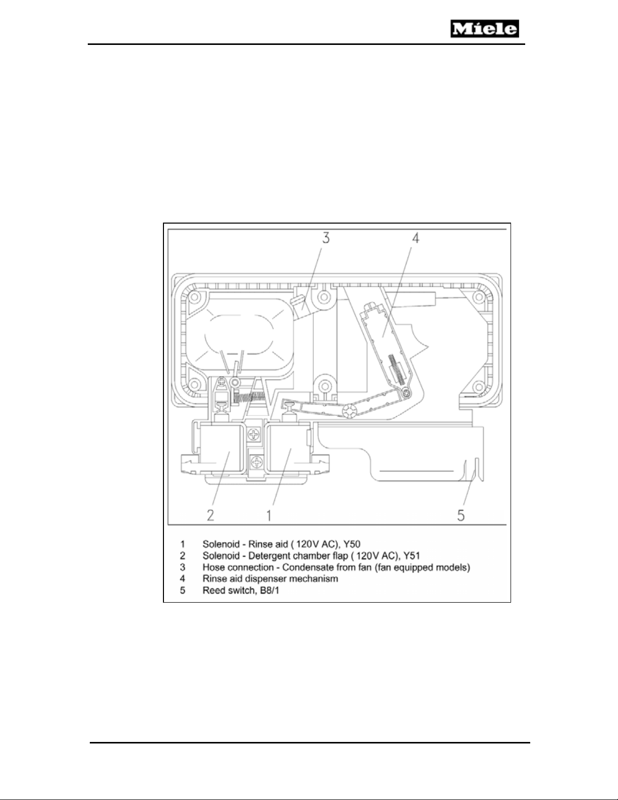
Figure 4-1: Dispenser Assembly
25
Technical Information
4.3.2 Dispensing
During the main wash, the Detergent Solenoid (Y51) is energized
(120VAC), to open the Detergent Dispenser Flap. The water jet from
the Middle Spray Arm flushes detergent out of the dispenser.
G600 & G800 Electronic Dishwashers
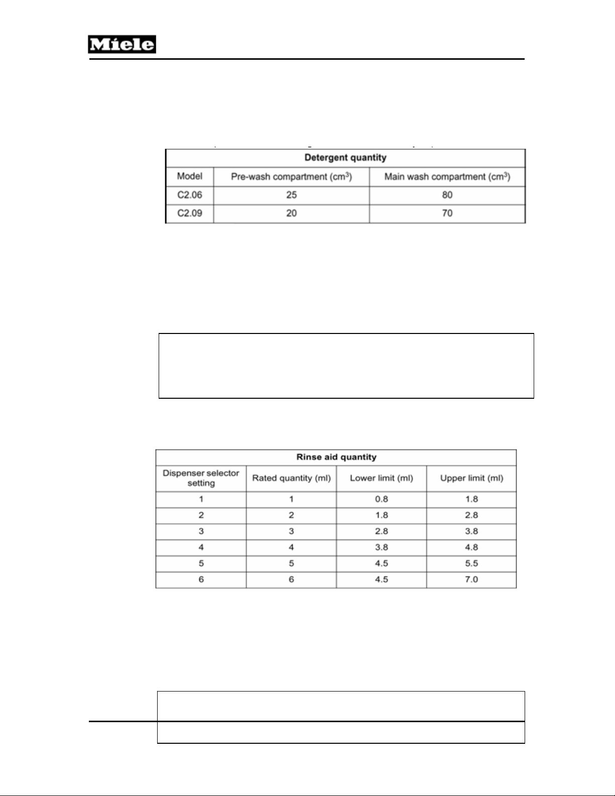
Table 4-1: Detergent quantity in Combination Dispensers C2.06 and C2.09.
During the final rinse the Rinse Aid Solenoid (Y50) is energized
(120VAC), to open the dispenser chamber and allow Rinse Aid to be
dispensed into the cabinet.
Note
The Rinse Aid only flows from the reservoir into the dispenser chamber
when the front door is fully opened at the end of a program.
The quantity taken into the dispenser chamber depends on the
dispenser selector setting.
Table 4-2: Rinse Aid Dispensing (Combination Dispensers C2.06 and C2.09).
When the Rinse Aid Light turns on, an additional 2 to 5 dispensings (at
setting 2) remain available.
26
G600 & G800 Electronic Dishwashers
Note
To allow proper filling of the Rinse Aid Dispenser; Rinse Aid should
only be added with the door in the fully open position.
4.4 Heaters
During the main wash and final rinse portions of a wash cycle, the
water is heated to the programs specified temperature before
advancing to the next step in the program (i.e.Thermal Stop).
The water is heated using one of two systems:
4.4.1 Wash Cavity Heating Element
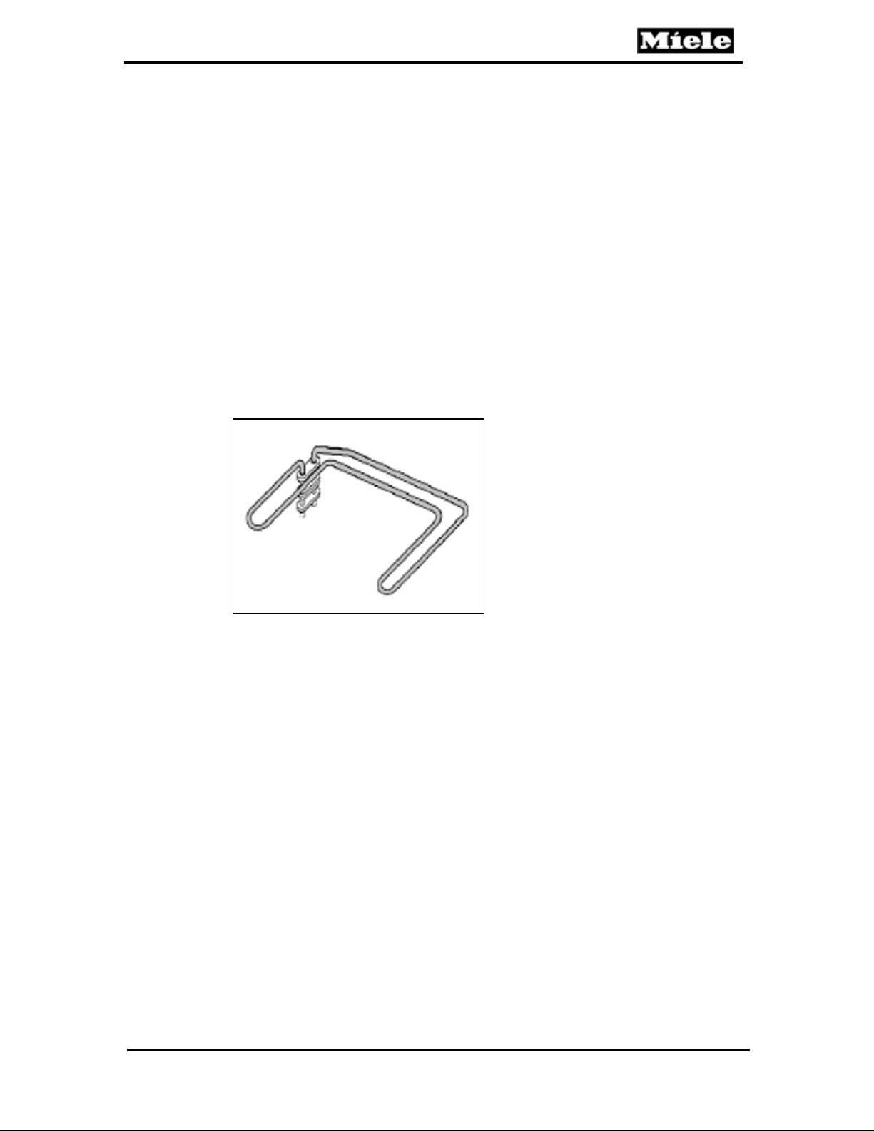
Figure 4-2: Cavity Style Heater Element
The Heating Element is mounted just off the floor of the wash cavity.
When powered (120 VAC) the element radiates heat thereby heating
the surrounding and circulating water. The temperature of
the water is monitored by the Temperature Sensor, mounted in the
Sump.
Heating Element switching is performed by the electronic via a Relay.
The relay (when energized) closes contacts to provide the Heater
Element with 120VAC. A Temperature Limiter mounted with the
element provides protection by opening up the circuit should the
temperature become to high.
Technical Information
27
Technical Information
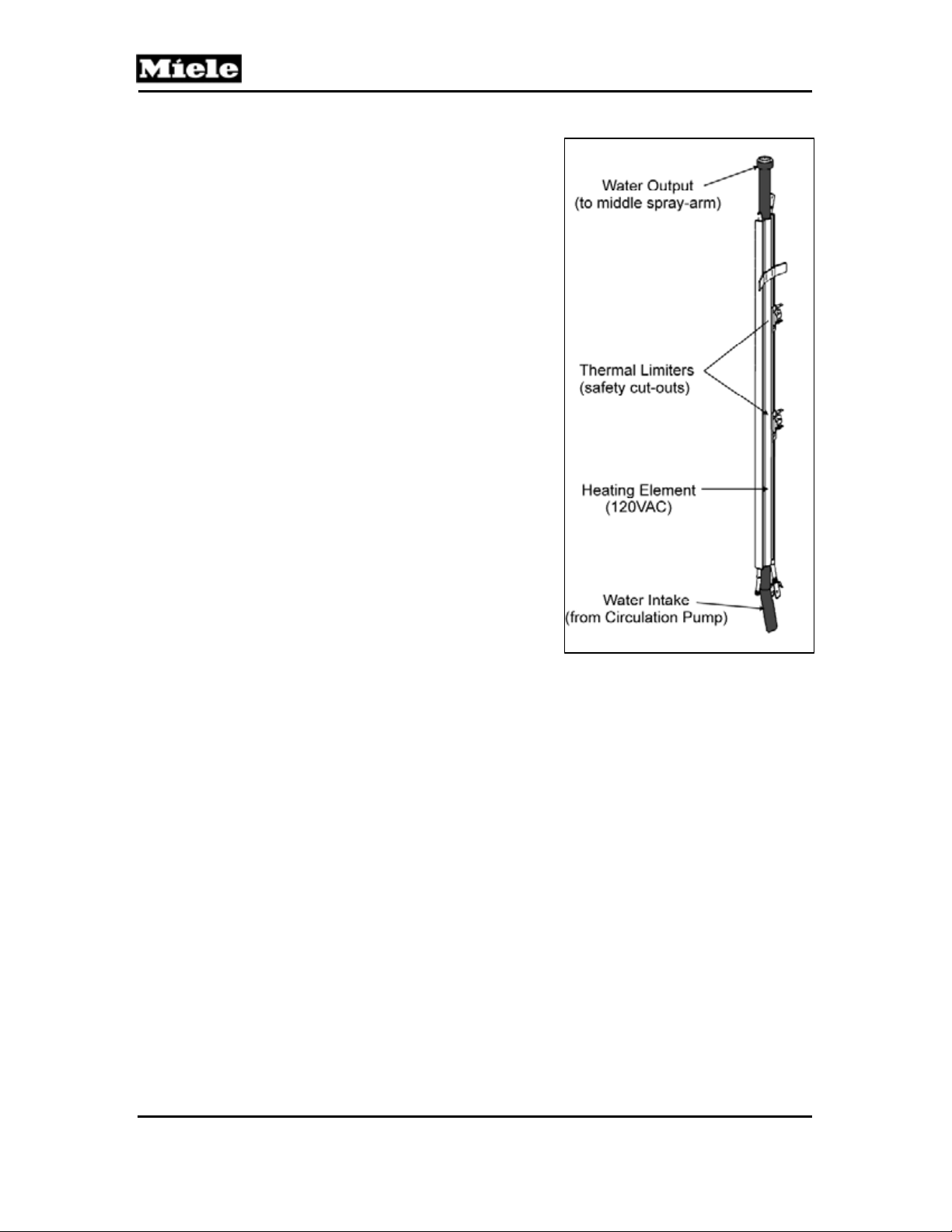
4.4.2 Flow Through Heater:
The Flow Through Heater
Assembly is mounted on the (left
side) exterior of the wash cabinet.
The Flow Through Heater is
plumbed into the water path
between the Circulation Pump
Output and the Middle Spray Arm.
The Flow Through Heater Consist
of a Heater Element mounted
parallel to a metal tube that water
passes through when the
dishwasher is circulating.
As water flows through the metal
tube; the water is heated and exits
through the Middle Spray-Arm. As
the water falls to the bottom of the
wash cavity, it passes through the
filter and re-enters the Circulation
Pump - the process then repeats.
The Temperature Sensor monitors
the water temperature until the
programs specified temperature is
reached. Generally the water heats Figure 4-3: Flow Through Heater
about 20 per minute.
Heating Element switching is performed by the electronic via a Relay.
The relay (when energized) closes contacts to provide the Heater
Element with 120VAC. Two Temperature Limiters are mounted along
the element and provides protection by opening up the circuit should
the temperature become to high.
4.4.2.1
Flow Through Heater Electrical Data
120VAC
1.5kW
9.6 k.Ohms
G600 & G800 Electronic Dishwashers
28
G600 & G800 Electronic Dishwashers
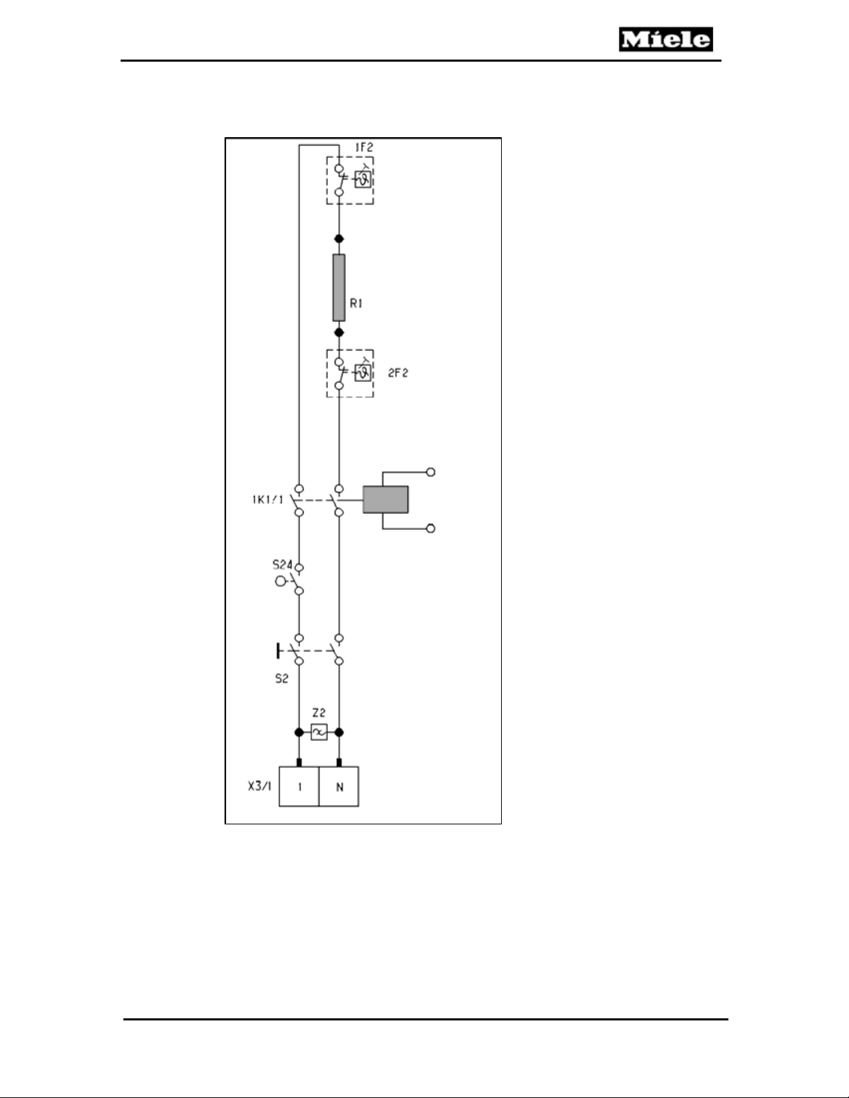
4.5 Heater Circuit - Operation
Technical Information
Figure 4-4: Heater Circuit
29

Technical Information
4.6 Pulsed Heating - Operation
In certain programs the heating may be operated at full power until a
water temperature of 77°F is reached; then power is applied in pulses.
This extends the heating time and allows enzyme-containing
detergents to develop their full cleaning potential.
The pulsed heating operates as follows:
• 1 min heater element on.
• 1 min heater element off.
The number of pulse cycles is limited to a maximum of 11. If the
programs specified temperature has not been reached, the heating
resumes using full power. Once the programs temperature has been
reached, the electronic unit advances to the next step in the program.
If the temperature cannot be reached (i.e. heater failure) within a
specified time, the program will advance; and a heating fault is stored
in the electronic.
G600 & G800 Electronic Dishwashers
4.7 Temperature Protection
The Flow-through Heater uses two (2) Temperature Limiters (2F2)
mounted on the body of the Flow-Through Heater. The Temperature
Limiters are designed to open the circuit should the temperature
become too high. When the temperature falls, the Temperature
Limiters do not reset automatically and must be reset manually (via the
red button on the back of the device).
Additional protection is provided by the Electronic, which switches the
appliance off and stores an F4 fault code, should the temperature
exceed 194°F (90°C) – as determined by the Temperature Sensor.
4.8 Static Drying
The Static Drying System uses no electrical and / or mechanical
components to assist in drying. With this system the final rinse water is
heated to 154°F (68°C) (not the usual 150°F / 67°C). The dishwasher
cabinet is made of stainless steel; and conducts the heat generated
during the final rinse. As the final rinse ends this stored thermal energy
radiates and assists in the drying.
30
Loading...