


Installation instructions
for freestanding, built-under and integrated dishwashers
It is essential to read the operating and installation instructions before
installing or using the machine, to avoid the risk of accident or damage to the machine.
G
M.-Nr. 05 565 043

These installation instructions apply to several different dishwasher models. Model numbers in this booklet refer to the model designation specified
on the data plate on the machine (and not the description on the control panel). The data plate is located at the top of the door when open.
The model numbers quoted refer only to the basic model number, e.g. the G 641 SCi is described as the G 641 in this booklet.
It is essential to read the Warning and Safety Instructions in the Operating Instruction booklet before installing the dishwasher.
2

Contents
Installing a freestanding dishwasher. . . . . . . . . . . . . . . . . . . . . . . . . . . . . . . . . . 4
Installing integrated "i" Dishwashers . . . . . . . . . . . . . . . . . . . . . . . . . . . . . . . . . 5 1. Fitting protective cover plate to worktop . . . . . . . . . . . . . . . . . . . . . . . . . . . . . . . 7 2. Fitting the facia panel . . . . . . . . . . . . . . . . . . . . . . . . . . . . . . . . . . . . . . . . . . . . . 8 3. Building the dishwasher into a niche. . . . . . . . . . . . . . . . . . . . . . . . . . . . . . . . . 10 Slides . . . . . . . . . . . . . . . . . . . . . . . . . . . . . . . . . . . . . . . . . . . . . . . . . . . . . . . . 10 Securing pieces . . . . . . . . . . . . . . . . . . . . . . . . . . . . . . . . . . . . . . . . . . . . . . . . 11 Angle connector . . . . . . . . . . . . . . . . . . . . . . . . . . . . . . . . . . . . . . . . . . . . . . . . 11 4. Matching the facia panel to the height of adjacent drawer fronts . . . . . . . . . . 13
5. Fitting the (matching) door front . . . . . . . . . . . . . . . . . . . . . . . . . . . . . . . . . . . . 14 Fitting the fixing bracket . . . . . . . . . . . . . . . . . . . . . . . . . . . . . . . . . . . . . . . . . . 14 Fitting and securing the door front . . . . . . . . . . . . . . . . . . . . . . . . . . . . . . . . . . 16 6. Securing the dishwasher. . . . . . . . . . . . . . . . . . . . . . . . . . . . . . . . . . . . . . . . . . . 18
7. Adjusting the door springs . . . . . . . . . . . . . . . . . . . . . . . . . . . . . . . . . . . . . . . . 19 8. Matching the plinth facing of a kitchen run . . . . . . . . . . . . . . . . . . . . . . . . . . . . 20
Installing built-under "U" model dishwashers . . . . . . . . . . . . . . . . . . . . . . . . . 21 1. Fitting protective cover plate to worktop . . . . . . . . . . . . . . . . . . . . . . . . . . . . . . 23 2. Building the dishwasher into its niche . . . . . . . . . . . . . . . . . . . . . . . . . . . . . . . . 24 Dishwasher height . . . . . . . . . . . . . . . . . . . . . . . . . . . . . . . . . . . . . . . . . . . . . . 25 Slides . . . . . . . . . . . . . . . . . . . . . . . . . . . . . . . . . . . . . . . . . . . . . . . . . . . . . . . . 25 Screw feet . . . . . . . . . . . . . . . . . . . . . . . . . . . . . . . . . . . . . . . . . . . . . . . . . . . . . 26 3. Calculate the decor panel height . . . . . . . . . . . . . . . . . . . . . . . . . . . . . . . . . . . 27
4. Matching the plinth facing of a kitchen run . . . . . . . . . . . . . . . . . . . . . . . . . . . . 28 5. Securing the dishwasher . . . . . . . . . . . . . . . . . . . . . . . . . . . . . . . . . . . . . . . . . . 31 6. Adjusting the door springs . . . . . . . . . . . . . . . . . . . . . . . . . . . . . . . . . . . . . . . . 32 7. Adjusting the plinth return . . . . . . . . . . . . . . . . . . . . . . . . . . . . . . . . . . . . . . . . . 33 8. Matching the plinth facing of a kitchen run . . . . . . . . . . . . . . . . . . . . . . . . . . . . 35
Electrical connection. . . . . . . . . . . . . . . . . . . . . . . . . . . . . . . . . . . . . . . . . . . . . . 36
Plumbing. . . . . . . . . . . . . . . . . . . . . . . . . . . . . . . . . . . . . . . . . . . . . . . . . . . . . . . . 38 Connection to the water inlet . . . . . . . . . . . . . . . . . . . . . . . . . . . . . . . . . . . . . . . . . 38 Drainage . . . . . . . . . . . . . . . . . . . . . . . . . . . . . . . . . . . . . . . . . . . . . . . . . . . . . . . . 39 Venting the drainage system . . . . . . . . . . . . . . . . . . . . . . . . . . . . . . . . . . . . . . 39
Optional accessories. . . . . . . . . . . . . . . . . . . . . . . . . . . . . . . . . . . . . . . . . . . . . . 40 "i"- Integrated dishwashers . . . . . . . . . . . . . . . . . . . . . . . . . . . . . . . . . . . . . . . . . . 40 Built-under "U" model dishwashers . . . . . . . . . . . . . . . . . . . . . . . . . . . . . . . . . . . . 40 Freestanding dishwasher. . . . . . . . . . . . . . . . . . . . . . . . . . . . . . . . . . . . . . . . . . . . 40
Technical data . . . . . . . . . . . . . . . . . . . . . . . . . . . . . . . . . . . . . . . . . . . . . . . . . . . 41
3

Installing a freestanding dishwasher
Freestanding dishwashers
Freestanding dishwashers do not require any special installation fixings in the kitchen, (except for plumbing and electrical connection points. See relevant sections at the end of this booklet).
Ensure that the drain hose, inlet hose and the electric cable are laid to reach the connection point without any kinks.
^The dishwasher must be level and stable when installed.
^Any unevenness in the floor level can be compensated for by adjusting the four screw feet.
Depending on model the adjustment range is:
– G 601 - G 632 2 cm (85-87 cm total height)
–G 646 - G 698, G 975 4 cm (85-89 cm total height)
4

Installing integrated "i" Dishwashers
Integrated ("i") dishwashers
"i" dishwashers are specially designed for building under a continuous worktop.
–The control panel with its accessories is included with the "i" dishwasher in a separate package for on-site fixing.
–The front of the dishwasher is designed to take a front panel. It can be fitted with a base unit door front to match the rest of the kitchen.
–The dishwasher does not have a plinth facing. The plinth area of the dishwasher needs to be covered either with a plinth facing to match the kitchen furniture or with one which can be ordered as a special accessory. The separate plinth facing can be height adjusted to suit the kitchen. The plinth return is freely adjustable.
Instructions for installing the dishwasher are described in the following sections.
An "i" model dishwasher can be converted into a built-under "U" dishwasher.
–A decor set GDU must be used.
–A plinth facing to cover the plinth area is supplied with the decor set. The plinth facing can be adjusted to match the height of adjacent plinths. The plinth return is freely adjustable.
The decor set is supplied with a separate installation booklet.
,To ensure stability, "i" and "U" model dishwashers must only be installed under a continuous worktop which must be securely screwed to neighbouring units.
,The dishwasher must not be installed under a hob. The high radiant temperatures which are sometimes generated by a hob could damage the dishwasher.
,On dishwashers with a drying fan, moist air is expelled through the vent outlet in the front of the machine at the end of a programme. It continues to be expelled for a certain length of time or until the door is opened.
To prevent damaging surrounding fittings (e. g. worktops with wood edging) the fan running time can be increased by 14 minutes (see "Additional functions" in the Operating Instruction manual for the machine).
5
Installing integrated "i" Dishwashers
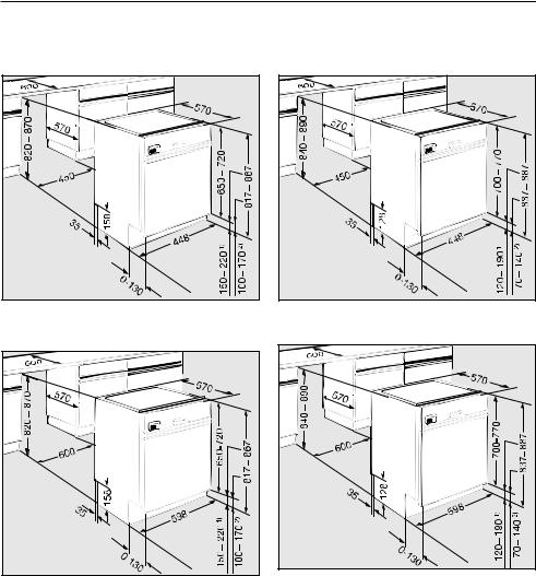
Building in dimensions
Dishwasher models G 601 - G 632 |
Dishwasher models |
G 636 - G 698, |
|
G 975 |
1)Niche height 870 mm
2)Niche height 820 mm
Adjustment range approx. 5 cm (82 -87 cm total height).
Extended machine feet are available at extra cost, (special accessory) where a machine height of 87 to 92 cm is required.
Dishwasher models G 801 - G 832 |
Dishwasher models G 836 - G 898 |
1)Niche height 890 mm
2)Niche height 840 mm
Adjustment range approx. 5 cm (84 - 89 cm total height).
Extended machine feet are available at extra cost, (special accessory) where a machine height of 89 to 94 cm is required.
6
Installing integrated "i" Dishwashers
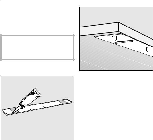
1.Fitting protective cover plate to worktop
The underside of the worktop is protected against steam rising from the machine by a special cover plate.
,If two different materials meet up at the front edge of the worktop, then the join must be concealed by the cover plate.
^Remove the protective backing from the cover plate.
^Squeeze sealant from the tube supplied all the way along the hollow moulding in the cover plate.
^Align the cover plate to the front edge of the worktop in the middle of the niche.
^Use the tacks supplied to nail the cover plate to the underside of the worktop.
Worktops with wood or laminate edging:
^Nail the tacks through the holes further back from the edge.
^Use soapy water to wipe off any excess sealant.
7
Installing integrated "i" Dishwashers
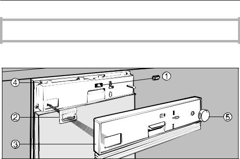
2. Fitting the facia panel
The dishwasher must not be used until the control panel has been correctly fitted.
Dishwashers with selector dial
(G 601 - G 624, G 638 - G 686, G 801 - G 824, G 838 - G 884, G 975)
^Attach cap a to push button switch.
^Push the ventillation grille b (depending on model) into position so that the slats on the grille are facing downwards.
^Place the facia panel c in position and use the six screws d to screw in place through from the inside of the door.
^Attach selector e.
8

Installing integrated "i" Dishwashers
Dishwashers with programme selector buttons
(G 632, G 692 - G 696, G 832, G 892 - G 896) |
^Attach cap a to push button switch.
^Push the ventillation grille b into position so that the slats on the grille are facing downwards.
^Place the facia panel c in position and use the six screws d to screw in place through from the inside of the door.
^Insert programme selector buttons e and function buttons f (the number of buttons will depend on model).
Dishwashers with programme buttons (G 698, G 898)
^Attach cap a to push button switch.
^Push the ventillation grille b into position so that the slats on the grille are facing downwards.
^Place the facia panel c in position and use the six screws d to screw in place through from the inside of the door.
9
Installing integrated "i" Dishwashers
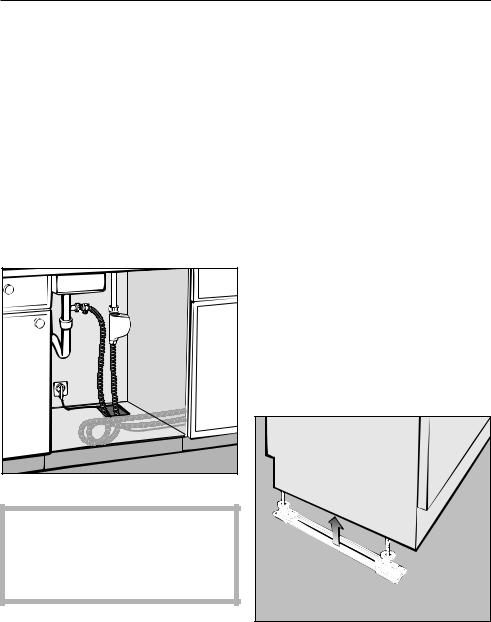
3.Building the dishwasher into a niche
Connection to water and drainage should be sited beside and not behind the dishwasher for accessibility. Connections are usually made in the area under the sink. Many kitchen unit manufacturers provide a cut-out in the base of the sink base unit for the hoses to be fed through.
If the base unit has no opening and if there is not an opening through the plinth area for connections, one must be cut.
Dimensions: 60 x 110 mm. |
,There must be no electrical sockets behind the dishwasher. Danger of overheating and fire risk if the dishwasher were to be pushed up against a plug.
Dishwasher height
^Adjust the height manually before installing the dishwasher.
Leave a space of approx. 5 mm below the worktop to allow the dishwasher to be pushed back easily into the recess. Make sure that the dishwasher stands level.
It is easier to adjust the screw feet if the weight of the dishwasher is not bearing down on them.
If possible tip the machine slightly.
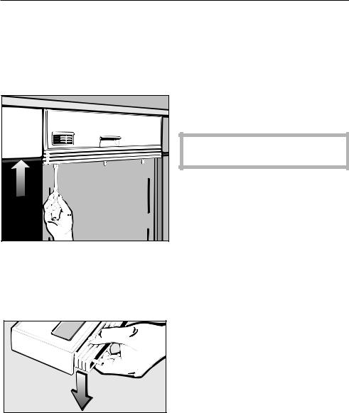
Slides
You will find the slides in the upper basket of the dishwasher.
They make installation of the dishwasher easier and protect the floor from possible damage when moving the appliance into and out of the recess. They are also used for adjusting the height of the rear screw feet.
^Fit the slides - with the ratchet at the rear - under the screw feet.
10
Installing integrated "i" Dishwashers
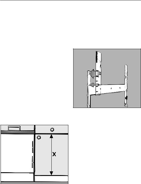
Securing pieces
To ensure stability, the dishwasher must be fixed securely to the worktop (step 6). Two securing pieces are supplied for this purpose.
^Fit the securing pieces into the slots on both the left and right hand sides.
Granite and marble worktops:
With these worktops the dishwasher must be securely screwed to neighbouring units on the right and left hand sides. For this you will require two special fixing brackets (these are included in the accessory pack together with fitting instructions and screws).
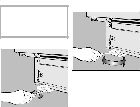
Angle connector
The angle connector for the water drainage hose at the rear of the dishwasher can be turned.
^Turn the angle connector in the direction of the on-site connection for the drainage hose.
^Push the dishwasher right back into the recess. Ensure that the drain hose, inlet hose and the electric cable are laid to reach the connection point without any kinks.
11
Installing integrated "i" Dishwashers
Now adjust the feet until the seal on the top of the dishwasher is right up against the underside of the worktop, to which it will be screwed later. Ensure that the dishwasher stands level.
Rear screw feet
^Use a TORX T20 screwdriver to adjust the rear screw feet to the required height.
Higher = turn clockwise
Lower = turn anti-clockwise
Several turns are needed to adjust 1 mm in height.
Front screw feet
^Adjust the front screw feet manually or with a flat blade screwdriver.
12
Installing integrated "i" Dishwashers
4.Matching the facia panel to the height of adjacent drawer fronts
The facia panel can be aligned with the drawer fronts by adjusting the spacer bars.
^Using an 8 mm socket spanner turn clockwise or anti-clockwise until the required height is reached.
If necessary some or all spacer bars can be removed.
^Press out the spacer bars from the fitting slits in the facia panel.
Adjustment range:
from 112 mm: Facia panel without spacer bars
to 145 mm: Facia panel with up to 4 spacer bars
to 154 mm: when using an extra (fifth) spacer bar (special accessory at extra cost)
After adjustment cut off any protruding lengths of screws.
13
Installing integrated "i" Dishwashers
5.Fitting the (matching) door front
Fixing brackets are already fitted on stainless steel door fronts. These fronts cannot be shortened.
(Go to "Fitting and securing the door front".)
The door of a kitchen base unit (without drawer front or fittings) is normally used for the door front.
If a kitchen door front is not available, a panel with the following dimensions may be used:
Width: depending on model
G 601 - G 632 }
440 - 447 mm
G 801 - G 832
G 636 - G 698, G 975 }
590 - 597 mm
G 836 - G 898
Thickness:
the same thickness as the neighbouring door fronts but a minimum of 16 mm.
Height: |
Dimension X |
14 |
Fitting the fixing bracket
A fixing bracket must be fitted to the rear of the door front panel. This is then used for attaching the door front panel to the door outer panel on the machine.
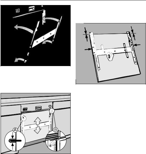
Templates are provided to position the fixing bracket and the door front accurately.
^On each side of the fixing bracket position a template with the rule markings facing outwards.
Installing integrated "i" Dishwashers
^Hang the fixing bracket into the slits in the machine door outer panel.
^Push the overhanging ends of the templates under the facia panel.
^Adjust the fixing bracket a:
The long holes in the machine outer door must be aligned with the matching markings on the template.
^Mark the height of the top edge of adjacent kitchen base unit doors on the template b.
^Take off the fixing bracket.
^Lay the door front down with the rear side facing upwards.
^Lay the bracket on the rear side of the door front and adjust so that:
–the marks on the template for the upper edge of the adjacent base unit doors match the top edge of the door front.
–the fixing bracket must be the same distance from the left and right hand side edges of the door front.
^Use strips of adhesive tape to hold the bracket in this position.
15
 Loading...