


 Loading...
Miele A 300/2, A 300/3, A 301/4, A 301/5, A 302/2 Operating instructions
...A 300/2, A 300/3,
A 301/4, A 301/5,
A 302/2, A 302/3
en Operating instructions Injector modules ja - ko
ru Инструкция по эксплуатации Инжекторные модули tr Kullanım kılavuzu Enjektör modülleri
zh
M.-Nr. 10 318 190
en ...................................................................................................................................... |
4 |
ja ....................................................................................................................................... |
23 |
ko ...................................................................................................................................... |
42 |
ru ....................................................................................................................................... |
61 |
tr ........................................................................................................................................ |
82 |
zh ....................................................................................................................................... |
101 |
2

|
en - Contents |
Notes about these instructions.......................................................................................... |
4 |
Queries and technical problems............................................................................................ |
4 |
Intended use ........................................................................................................................ |
5 |
Items supplied ..................................................................................................................... |
6 |
A 300/2 .................................................................................................................................. |
6 |
A 300/3 .................................................................................................................................. |
6 |
Additional components for A 300/2 and A 300/3.................................................................. |
7 |
A 301/4 .................................................................................................................................. |
8 |
A 301/5 .................................................................................................................................. |
8 |
Additional components for A 301/4 and A 301/5.................................................................. |
9 |
A 302/2 ................................................................................................................................ |
10 |
A 302/3 ................................................................................................................................ |
10 |
Additional components for A 302/2 and A 302/3................................................................ |
11 |
Disposal of the packing material ........................................................................................ |
11 |
Warning and Safety instructions...................................................................................... |
12 |
Installation.......................................................................................................................... |
13 |
Injector nozzles.................................................................................................................... |
13 |
Tools required:................................................................................................................ |
13 |
Screwing in injector nozzles .......................................................................................... |
13 |
Shortening the supports................................................................................................. |
13 |
Holding rack ........................................................................................................................ |
14 |
Securing the holding rack .............................................................................................. |
14 |
Removing the holding rack............................................................................................. |
14 |
Areas of application .......................................................................................................... |
15 |
Injector modules.................................................................................................................. |
15 |
Inserting an injector module........................................................................................... |
15 |
Removing an injector module......................................................................................... |
15 |
Sample loads....................................................................................................................... |
16 |
Shapes of items.............................................................................................................. |
16 |
A 300/2 and A 300/3 ...................................................................................................... |
16 |
A 301/4 and A 301/5 ...................................................................................................... |
16 |
Butyrometers.................................................................................................................. |
17 |
A 302/2 and A 302/3 ...................................................................................................... |
17 |
Preparing the load ............................................................................................................... |
18 |
Before loading the machine and before starting a programme .......................................... |
21 |
Rinse nozzle for powder dispenser ..................................................................................... |
21 |
3

en - Notes about these instructions
Important warnings
Information which is important for safety is highlighted in a thick framed box with a warning symbol. This alerts you to the potential danger of injury to people or damage to property.
Read these warning notes carefully and observe the procedural instructions and codes of practice they describe.
Notes
Information of particular importance that must be observed is highlighted in a thick framed box.
Additional information and comments
Additional information and comments are contained in a simple frame.
Operating steps
Operating steps are indicated by a black square bullet point.
Example:
Select an option using the arrow buttons and save your choice with
OK.
Display
Certain functions are shown in display messages using the same font as that used for the function itself in the display.
Example:
Settings menu.
Queries and technical problems
In the event of queries or technical problems, please contact Miele. Contact details can be found at the end of the operating instructions for your cleaning machine or at www.miele.com/professional.
4

en - Intended use
This module can be used to reprocess machine-reprocessable laboratory glassware and utensils in a Miele washer-disinfector for laboratory glassware and utensils. Follow the operating instructions for your washer-disinfector as well as the instructions of the glassware and utensil manufacturer on how to reprocess their items by machine.
The A 300/2, A 300/3, A 301/4, A 301/5, A 302/2 and A 302/3 injector modules are suitable for reprocessing narrow-necked laboratory glassware.
The modules can be used in the following baskets:
–Upper basket A 100
–Lower basket A 150
In some cases, the modules are supplied without injector nozzles. Miele offers a wide range of different injector nozzles for reprocessing narrow-necked laboratory glassware which can be fitted based on the relevant requirements.
The washer-disinfector is generally referred to as “the machine” in these operating instructions. Reprocessable laboratory glassware and utensils are referred to as “items” if they are not more closely defined.
5
en - Items supplied
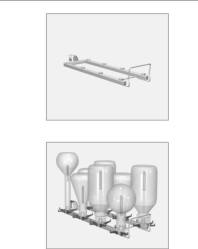
A 300/2
– Injector module, height 73 mm, width 133 mm, depth 475 mm.
A 300/3
– Injector module, height 73 mm, width 133 mm, depth 475 mm.
Items supplied – 4 x A 840, injector nozzle with plastic support, for load items with an opening width of 12 to 85 mm, length 130 mm, Ø 6 mm
–4 x A 841, injector nozzle with plastic support, for load items with an opening width of 12 to 85 mm, length 210 mm, Ø 6 mm
6
en - Items supplied
Additional components for A 300/2 and A 300/3
–A 802 rinse nozzle for powder dispenser
–A 840, injector nozzle with plastic support, for load items with an opening width of 12 to 85 mm, length 130 mm, Ø 6 mm
–A 841, injector nozzle with plastic support, for load items with an opening width of 12 to 85 mm, length 210 mm, Ø 6 mm
Nozzles with different diameters can be fitted on the modules as required.
However, the different diameters will affect the wash pressure and hence the cleaning performance.
Please speak to the Miele Customer Service Department if you wish to use nozzles with different diameters.
–A 860, holding rack with centring aids for the A 300/2 and A 300/3 modules
Further components are available from Miele as optional extras.
7

en - Items supplied
A 301/4
– Injector module, height 73 mm, width 173 mm, depth 475 mm.
A 301/5
– Injector module, height 73 mm, width 173 mm, depth 475 mm.
Items supplied – 9 x A 842, injector nozzle with plastic support, for load items with an opening width of 10 to 70 mm, length 90 mm, Ø 4 mm
–9 x A 843, injector nozzle with plastic support, for load items with an opening width of 10 to 70 mm, length 185 mm, Ø 4 mm
8
en - Items supplied
Additional components for A 301/4 and A 301/5
–A 802 rinse nozzle for powder dispenser
–A 842, injector nozzle with plastic support, for load items with an opening width of 10 to 70 mm, length 90 mm, Ø 4 mm
–A 843, injector nozzle with plastic support, for load items with an opening width of 10 to 70 mm, length 185 mm, Ø 4 mm
Nozzles with different diameters can be fitted on the modules as required.
However, the different diameters will affect the wash pressure and hence the cleaning performance.
Please speak to the Miele Customer Service Department if you wish to use nozzles with different diameters.
–A 861, holding rack with centring aids for the A 301/4 and A 301/5 modules
The A 861 holding rack can only be retrofitted in the case of modules that are used exclusively in the A 150 lower basket.
–SD-B, injector nozzle for butyrometers, length 140 mm, Ø 4 mm, plus welded, compressed nozzle, length 100 mm, Ø 1.5 mm
Further components are available from Miele as optional extras.
9
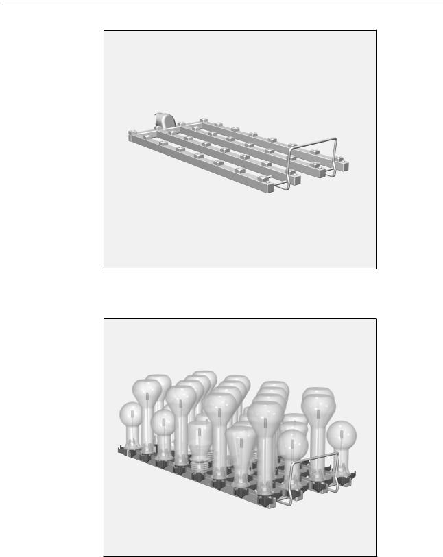
en - Items supplied
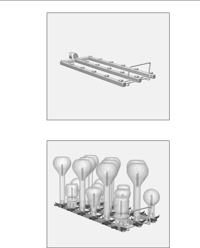
A 302/2
– Injector module, height 73 mm, width 195 mm, depth 475 mm.
A 302/3
– Injector module, height 73 mm, width 195 mm, depth 475 mm.
Items supplied – 16 x A 844, injector nozzle with plastic support, for load items with an opening width of 6 to 55 mm, length 80 mm, Ø 2.5 mm
–16 x A 845, injector nozzle with plastic support, for load items with an opening width of 6 to 55 mm, length 125 mm, Ø 2.5 mm
10
en - Items supplied
Additional components for A 302/2 and A 302/3
–A 802 rinse nozzle for powder dispenser
–A 844, injector nozzle with plastic support, for load items with an opening width of 6 to 55 mm, length 80 mm, Ø 2.5 mm
–A 845, injector nozzle with plastic support, for load items with an opening width of 6 to 55 mm, length 125 mm, Ø 2.5 mm
Nozzles with different diameters can be fitted on the modules as required.
However, the different diameters will affect the wash pressure and hence the cleaning performance.
Please speak to the Miele Customer Service Department if you wish to use nozzles with different diameters.
–A 862, holding rack with coating for the A 302/2 and A 302/3 modules
Further components are available from Miele as optional extras.
Disposal of the packing material
The packaging is designed to protect against transportation damage. The packaging materials used are selected from materials which are environmentally friendly for disposal and should be recycled.
Recycling the packaging reduces the use of raw materials in the manufacturing process and also reduces the amount of waste in landfill sites.
11

en - Warning and Safety instructions
To avoid the risk of accidents and damage to this module please read these instructions carefully before using it for the first time. Keep these instructions in a safe place where they are accessible to users at all times.
Please also read the operating instructions for your washerdisinfector and pay particular attention to the Warning and Safety instructions.
The module is approved solely for the applications specified in the “Areas of application” chapter of these operating instructions. Components such as nozzles may only be replaced with Miele components or genuine original spare parts.
New load carriers must be cleaned in the washer-disinfector without a load prior to first use.
Inspect all mobile units, baskets, modules and inserts daily as described in the “Maintenance” section in the Operating instructions for the washer-disinfector.
Only items which have been declared by their manufacturer as suitable for machine reprocessing may be processed. The manufacturer's specific reprocessing instructions must be observed.
Broken glass can result in serious injury when loading or unloading. Broken glass items must not be processed in the machine.
Only place empty, unloaded modules in baskets. Check that they are correctly engaged before loading them.
Modules must be completely emptied before taking them out. Placing loaded modules in baskets or removing them can cause damage to the wash load and cause injury should glassware be broken.
The reprocessing result must be checked as necessary using a suitable test method and not just by a visual check.
12
en - Installation
Injector nozzles
Tools required: – 9 mm Spanner (WAF 9)
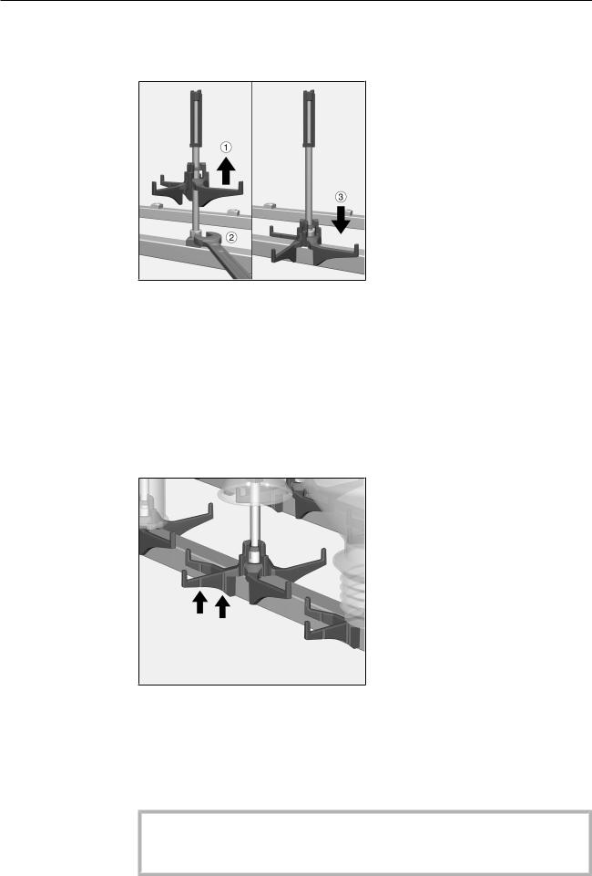
Screwing in injector nozzles
Lift up the injector nozzle support and screw the nozzle into the required position .
Use the spanner to tighten the injector nozzle .
Slide the support downwards until it rests on the water supply pipe
.
Shortening the If the nozzle supports collide with the rods of the module load carriers supports or the water connection of the module following installation, the sup-
ports can be shortened. Predetermined breaking points are provided on the supports for this purpose.
The predetermined breaking points are indicated by notches in the sides of the supports, shown here on the A 840 injector nozzle.
Bend the support to one side at the predetermined breaking point until the end piece breaks off. You can also use a tool, e.g. wire cutters or a strong pair of scissors, to cut through the support at the predetermined breaking point.
The supports stabilise the load items during reprocessing.
For this reason, the supports should only be shortened when abso-
lutely necessary.
13
en - Installation
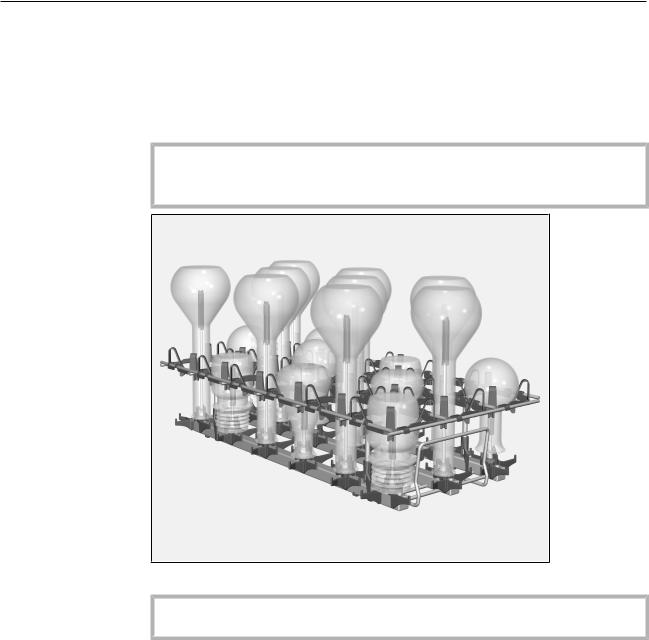
Holding rack
An additional holding rack can be mounted when reprocessing particularly fragile load items. This prevents them from touching each other if they are moved by the force of water during reprocessing.
The holding racks are tailored to the size of the modules and can be retrofitted at any time.
Do not pull on the holding racks or lift the modules by the holding racks.
The load items could be damaged or the holding racks could come loose from the modules.
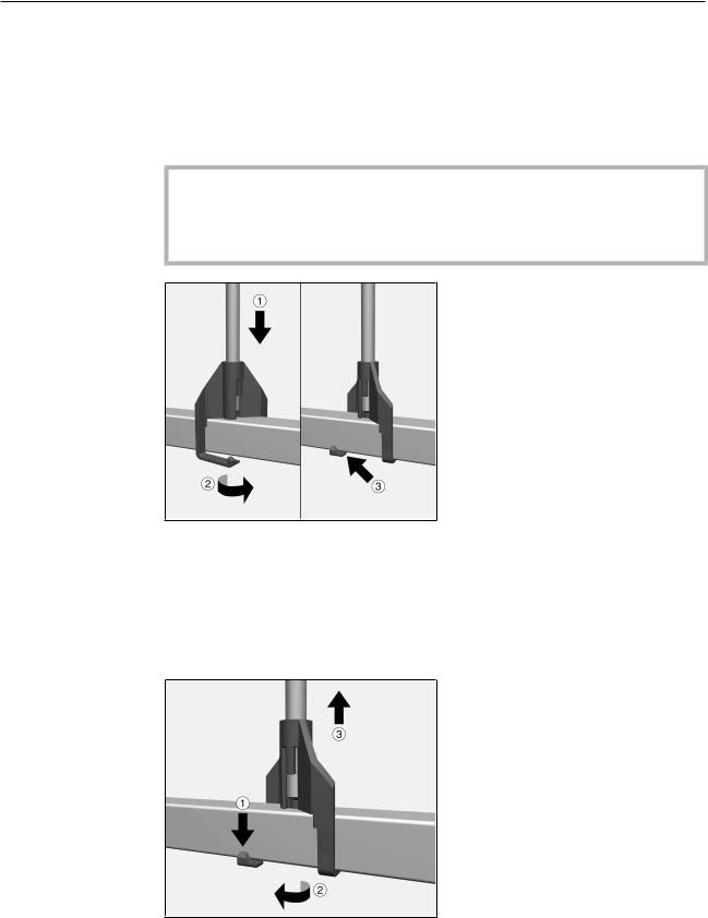
Securing the holding rack
Position the rods of the holding rack on the module with the holders
.
Turn the holders on the rods of the holding rack .
The locking retainers on the holders lock into place .
Repeat the process for the other 3 rods.
Removing the holding rack
Pull the locking retainers on the holders downwards slightly and turn the holders .
Repeat the process for the other 3 rods.
Lift the holding rack off the module .
14
en - Areas of application
Inserting an injector module
Removing an injector module
Injector modules
Only place empty, unloaded modules in baskets. Check that they are correctly engaged before loading them.
Modules must be completely emptied before taking them out. Placing loaded modules in baskets or removing them can cause damage to the wash load and cause injury should glassware be broken.
The injector module is only suitable for use in an A 100 upper basket or an A 150 lower basket. The injector nozzles must point upwards.
Carefully slide the injector module in and connect it to the water connection point.
Then press down on the module to secure it on the rails in the basket.
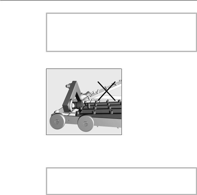
Do not hold the basket by the injector module when removing it
from the cleaning machine.
The module could come loose or the water connection could be
damaged.
Release the module from the locking mechanism and pull it out of the water connection at a flat angle. If the module is removed at too steep an angle, the lever action may damage the connection point and the connector.
15

en - Areas of application
Shapes of items
A 300/2 and
A 300/3
A 301/4 and
A 301/5
Sample loads
Laboratory |
Round flasks |
Erlenmeyer |
Measuring |
flasks |
|
flasks |
flasks |
|
|
|
|
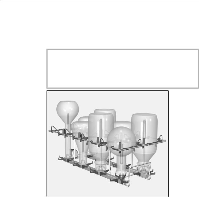
The A 300/2 and A 300/3 modules each have 8 positions for reprocessing load items. The modules are designed for load items with a volume from 200 ml to 1000 ml.
Capacity
Volume |
Laboratory |
Round |
Erlenmeyer |
Measuring |
[ml] |
flasks |
flasks |
flasks |
flasks |
200–500 |
max. 8 |
max. 8 |
max. 8 |
1) |
max. 8 |
||||
1000 |
1) |
2) |
2) |
1), 2) |
max. 8 |
max. 4 |
max. 4 |
max. 4 |
1)may not be suitable for use in the upper basket due to height of load items
2)plus 4 x load items with a smaller volume
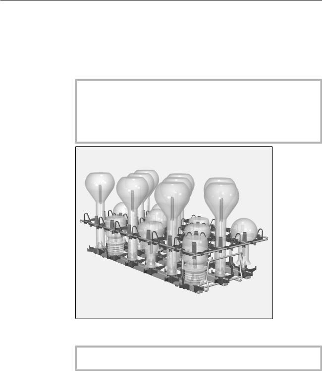
The A 301/4 and A 301/5 modules each have 18 positions for reprocessing load items. The modules are designed for load items with a volume from 50 ml to 250 ml.
Capacity
Volume |
Laboratory |
Round |
Erlenmeyer |
Measuring |
[ml] |
flasks |
flasks |
flasks |
flasks |
50 |
max. 18 |
max. 18 |
max. 18 |
1) |
max. 18 |
||||
100–150 |
max. 18 |
max. 18 |
max. 18 |
max. 18 |
|
|
|
|
|
200 |
max. 18 |
2) |
2) |
3) |
max. 9 |
max. 9 |
max. 18 |
||
250 |
max. 18 |
2) |
2) |
2), 3) |
max. 9 |
max. 9 |
max. 9 |
1)A 845 injector nozzle is recommended
2)plus 9 x load items with a smaller volume
3)may not be suitable for use in the upper basket due to height of load items
16
en - Areas of application
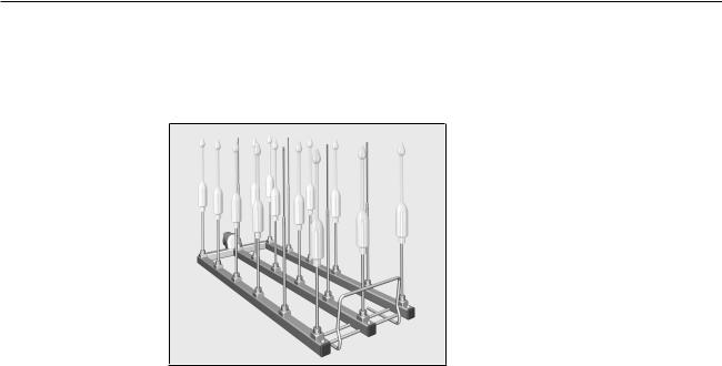
Butyrometers The A 301/4 or A 301/5 modules are recommended for reprocessing butyrometers.
The modules must be equipped with the SD-B nozzles for reprocessing butyrometers.
Due to the height of the nozzles, the module may only be used in the A 150 lower basket. It is not possible to use an upper basket at the same time.
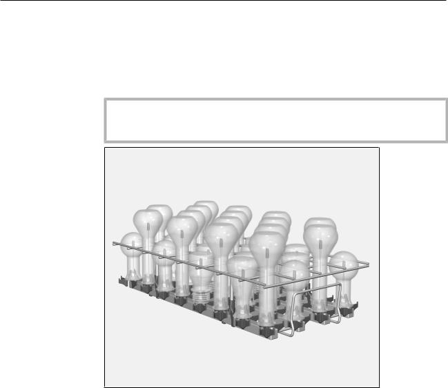
A 302/2 and |
The A 302/2 and A 302/3 modules each have 32 positions for repro- |
|||||
A 302/3 |
cessing load items. The modules are designed for load items with a |
|||||
|
volume from 20 ml to 100 ml. |
|
|
|
||
|
Capacity |
|
|
|
|
|
|
|
|
|
|
|
|
|
Volume |
Laboratory |
|
Round |
Erlenmeyer |
Measuring |
|
[ml] |
flasks |
|
flasks |
flasks |
flasks |
|
20–50 |
max. 32 |
|
max. 32 |
max. 32 |
max. 32 |
|
|
|
|
|
|
|
|
100 |
1) |
|
2) |
2) |
2), 3) |
|
max. 32 |
|
max. 16 |
max. 16 |
max. 16 |
|
1)the A 862 holding rack cannot hold any 100 ml laboratory flasks
2)plus 16 x load items with a smaller volume
3)A 843 injector nozzle required
17
en - Areas of application
Preparing the load
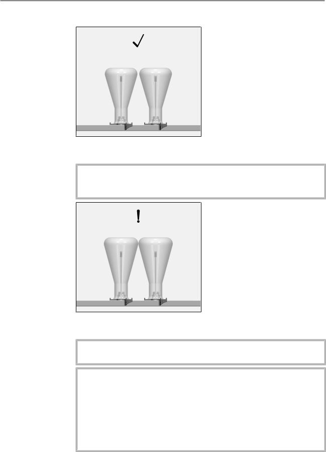
Ideally, a gap should be left between neighbouring items when they are reprocessed.
An additional frame can be mounted when reprocessing particularly fragile items. This prevents them from touching each other if they are moved by the force of water during reprocessing.
If bulbous items are loaded in neighbouring positions in the module, the items may touch each other.
If the cleaning and rinsing requirements are particularly high, a different position must be selected on the module for these items.
Damage to the items.
If items touch each other during reprocessing, damage can occur at the points of contact, for example, the items may become scratched or the glass may break.
If the items are fragile:
–Select a different position on the module
–Use a frame
–Select a module with a greater distance between the nozzles
18
en - Areas of application
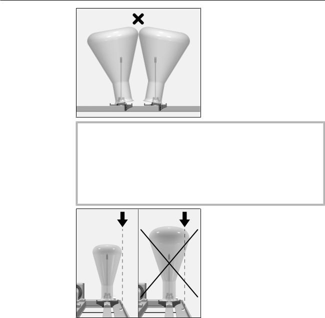
Damage to the items.
The rims of the items should rest fully on the support of the injector nozzle. If items dislodge neighbouring nozzles, damage can occur during reprocessing, for example, the items may become scratched or the glass may break.
Use:
–A different position on the module
–A module with a greater distance between the nozzles
Glassware must not extend beyond the sides of the load carrier.
19
en - Areas of application
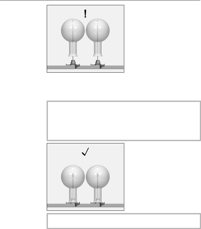
The tip of the nozzle is designed so that it can touch the bottom of a piece of glassware during reprocessing. The shape of the protective cap ensures that water can flow out of the nozzle during reprocessing.
Damage to the items.
If items are reprocessed frequently, their surfaces may be damaged at the point where the nozzle touches them, for example, the items may become scratched.
If the items are fragile, select a shorter nozzle to prevent the nozzle from coming into contact with the item.
If the cleaning and rinsing requirements are particularly high, a shorter nozzle must be selected.
20
en - Areas of application
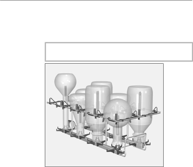
Before loading the machine and before starting a
programme
–Check that fittings such as irrigation sleeves and injector nozzles are securely screwed into position.
Make sure that all screw connectors are fitted with injector nozzles, adapters, irrigation sleeves or blind stoppers to ensure that all fittings in use are supplied with sufficient standardised pressure.
Damaged fittings such as injector nozzles, adapters and irrigation sleeves must not be used.
Fittings not equipped with wash items do not have to be replaced
blind stoppers.
–Check that the baskets and modules are correctly connected to the water supply.
Rinse nozzle for powder dispenser
If powder cleaning agent is used in combination with an upper basket and two modules in the lower basket in the case of cleaning machines with a powder dispenser in the door, an A 802 rinse nozzle for powder cleaning agent must be fitted.
This rinse nozzle flushes the powder cleaning agent out of the dispenser during reprocessing.
If liquid cleaning agent is dispensed, a rinse nozzle is not required.
The rinse nozzle must be fitted at the front left of the left-hand module in the lower basket:
Release the existing nozzle using a spanner and remove it.
Screw the rinse nozzle into the free holder and tighten with the spanner. The rinse opening must then be pointing forwards.
Load items must not be attached to the rinse nozzle.
21

ja - |
|
....................................................................................................................................... |
23 |
....................................................................................................................................................................... |
23 |
.................................................................................................................................................................... |
24 |
........................................................................................................................................................................ |
25 |
A 300/2.................................................................................................................................................................................................... |
25 |
A 300/3.................................................................................................................................................................................................... |
25 |
A 300/2 A 300/3 ....................................................................................................................................... |
26 |
A 301/4.................................................................................................................................................................................................... |
27 |
A 301/5.................................................................................................................................................................................................... |
27 |
A 301/4 A 301/5 ....................................................................................................................................... |
28 |
A 302/2.................................................................................................................................................................................................... |
29 |
A 302/3.................................................................................................................................................................................................... |
29 |
A 302/2 A 302/3 ...................................................................................................................................... |
30 |
............................................................................................................................................................................................. |
30 |
............................................................................................................................................... |
31 |
........................................................................................................................................................................... |
32 |
............................................................................................................................................................................... |
32 |
....................................................................................................................................................................................... |
32 |
............................................................................................................................................................ |
32 |
............................................................................................................................................................................ |
32 |
.......................................................................................................................................................................................... |
33 |
................................................................................................................................................................................... |
33 |
............................................................................................................................................................................. |
33 |
............................................................................................................................................... |
34 |
....................................................................................................................................................................... |
34 |
..................................................................................................................................................... |
34 |
............................................................................................................................................. |
34 |
........................................................................................................................................................................... |
35 |
................................................................................................................................................................................... |
35 |
A 300/2 A 300/3....................................................................................................................................................................... |
35 |
A 301/4 A 301/5....................................................................................................................................................................... |
35 |
................................................................................................................................................................................................... |
36 |
A 302/2 A 302/3....................................................................................................................................................................... |
36 |
.............................................................................................................................................................................................. |
37 |
......................................................................................................................... |
40 |
........................................................................................................................................................................... |
40 |
22

ja -
ます。この注意は、人体の怪我または器物破損の潜在的危険に対しての警告です。
OK
先の詳細は、お使いの洗浄機の取扱説明書の最後をご覧ください。
23

ja -
A 300/2, A 300/3, A 301/4, A 301/5, A 302/2
A 302/3
–A 100
–A 150
“ ” “ ”
24

ja -
A 300/2
– 73 mm 133 mm 475 mm
A 300/3
|
– 73 mm 133 mm 475 mm |
|
– A 840 x 4, 12 85mm 130mm |
|
φ6mm |
|
– A 841 x 4, 12 85mm 210mm |
|
φ6mm |
25
ja -
A 300/2 A 300/3
–A 802
–A 840, 12 85mm 130mm
φ6mm
– A 841, 12 85mm 210mmφ6mm
– A 860 A 300/2 A 300/3
26
ja -
A 301/4
– 73 mm 173 mm 475 mm
A 301/5
|
– 73 mm 173 mm 475 mm |
|
– A 842 x 9, 10 70mm 90mm |
|
φ4mm |
|
– A 843 x 9, 10 70mm 185mm |
|
φ4mm |
27
ja -
A 301/4 A 301/5
–A 802
–A 842, 10 70mm 90mm
φ4mm
– A 843, 10 70mm 185mmφ4mm
– A 861 A 301/4 A 301/5
A 861 A 150
– SD-B, 140mm φ4mm
100mm φ1.5mm
28

ja -
A 302/2
– 73 mm 195 mm 475 mm
A 302/3
|
– 73 mm 195 mm 475 mm |
|
– A 844 x 16, 6 55mm 80mm |
|
φ2.5mm |
|
– A 845 x 16, 6 55mm 125mm |
|
φ2.5mm |
29
ja -
A 302/2 A 302/3
–A 802
–A 844, 6 55mm 80mm
φ2.5mm
– A 845, 6 55mm 125mmφ2.5mm
– A 862 A 302/2 A 302/3
30
Loading...