


INDICE
Caratteristiche
Installazione Sostituzione del fusibile Montaggio dell’antenna Antenna base
Uso del ricetrasmettitore Canali prioritari (CH 9-19) Altoparlante supplementare Caratteristiche tecniche
pag. 2 pag. 3 pag. 4 pag. 4 pag. 5 pag. 5 pag. 5 pag. 5 pag. 6
ITALIANO
1
ITALIANO
CARATTERISTICHE
•Il PLL permette un controllo preciso delle frequenze e maggior stabilità su tutti i 40 canali, con controlli separati di scansione verso l’alto e verso il basso.
•I filtri ceramici proteggono dalle interferenze dei canali adiacenti.
•Il display mostra quale canale è attivato.
•Commutatore AM/FM per selezionare la modalità di emissione.
•Il LED rosso (TX) e il verde (RX), indicano la modalità operativa: RX=ricezione; TX= trasmissione.
•La regolazione del circuito squelch permette di eliminare i fastidiosi rumori in fase di ricezione.
•La presa esterna sul retro consente l’utilizzo di un eventuale altoparlante supplementare.
•Il commutatore d’emergenza permette la commutazione immediata dal CH 9 al 19.
•É funzionante con corrente negativa a massa 12-13.8V.
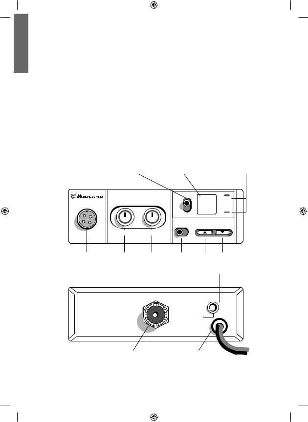
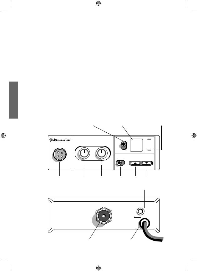
COMANDI
Commutatore canali |
Display canali |
LED RX |
prioritari CH-9/19 |
|
LED TX |
|
ALAN 100 PLUS |
|
40 |
TX |
|
|
|
|
9 |
|
RX |
|
|
|
CH |
|
|
|
|
|
19 |
|
|
|
|
|
FM AM |
CHANNEL |
|
|
SQUELCH |
ON/OFF VOL |
|
|
|
Presa microfono |
SQUELCH |
Accensione/Volume |
Commutatore |
Tasto cambio canale |
|
|
|
|
AM/FM |
|
|
|
|
|
Presa altoparlante esterno |
||
|
|
ANT |
|
EXT |
|
|
|
|
|
|
|
|
|
|
|
SPKR |
|
|
|
|
+ RED |
|
|
|
|
|
- |
BLK |
|
|
Connettore antenna |
Cavo alimentazione |
|
||
2
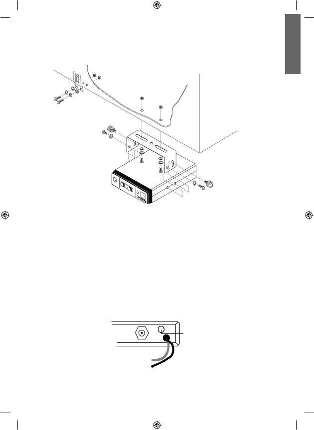
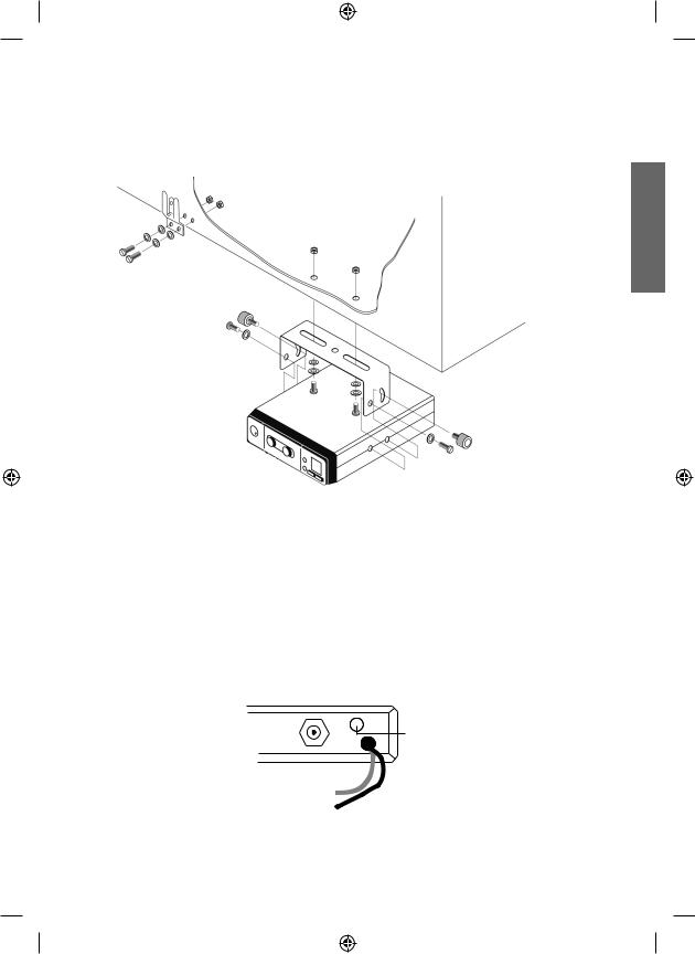
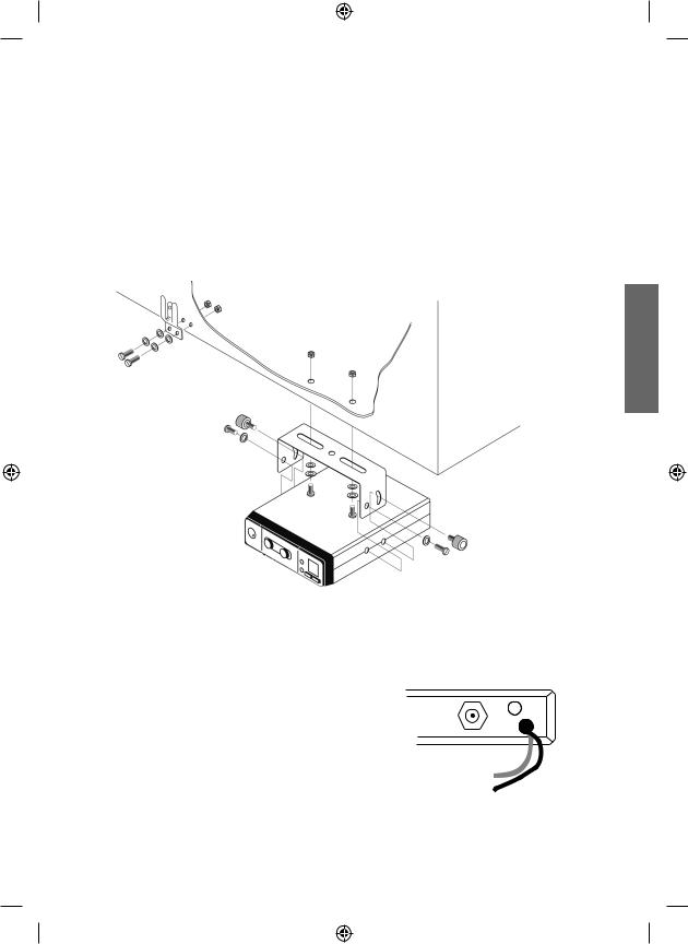
INSTALLAZIONE
|
Rondelle |
Dadi |
Viti |
|
|
|
|
Viti
Rondelle
Staffa
Rondelle
Viti
Rondelle
Viti
Ricercare e localizzare sul mezzo mobile, la posizione per l’installazione dell’apparato.
Tale posizionamento deve essere fatto in modo da non creare intralcio a chi guida, e nello stesso tempo, di facile accessibiltà per poter togliere l’apparato secondo le necessità.
La posizione di montaggio più comune è sotto il cruscotto (si sconsiglia vicino a fonti di calore o vicino al condizionatore). Dopo aver stabilito la posizione più adatta sul veicolo, mantenere il ricetrasmettitore con la staffa di montaggio nell’esatta posizione desiderata e verificare che non ci siano inconvenienti; successivamente segnare e forare il veicolo per il fissaggio delle viti di montaggio. Controllare che esse siano ben ancorate, in considerazione delle notevoli sollecitazioni e vibrazioni create dal mezzo mobile.
Inserire il cavo di alimentazione accendisigari da 12V nella relativa presa accendisigari.
Prima di operare, installare e collegare l’antenna inserendo il connettore nell’apposita presa sul retro dell’apparato. Per l’uso di un altoparlante esterno, utilizzare la presa EXT-SPKR.
EXT
ANT
SPKR +RED
-BLK
ITALIANO
3
ITALIANO
SOSTITUZIONE DEL FUSIBILE
Sostituire il fusibile del cavo di alimentazione con un similare a 2 A (Un fusibile di ricambio è in dotazione).
F2A 250V +
MONTAGGIO ANTENNA
L’antenna è l’elemento più importante per ottenere i migliori risultati. É indispensabile che l’antenna abbia un’impedenza di 50 Ohms. A seconda della posizione in cui viene installata, il rendimento varia notevolmente.
Usare un cavo coassiale con impedenza 50 Ohms. Sono consigliati i cavi RG 58U per lunghezza sotto i 2.5 metri, oppure RG 8 per lunghezze superiori.
Il cavo coassiale deve essere montato con molta cura: evitare curve e piegamenti. Inoltre va ricordato che il cavo più corto aumenta la sensibilità dell’apparato, così pure un cattivo collegamento tra apparato e antenna.
Consigli:
•Montare l’antenna nel posto più libero e più alto dell’auto.
•L’antenna deve essere installata in posizione verticale, e così deve rimanere anche quando il veicolo è in moto.
•Montare l’antenna e il cavo il più possibile lontano da fonti di rumore.
•La massa dell’antenna deve coprire un’area di 1m2.
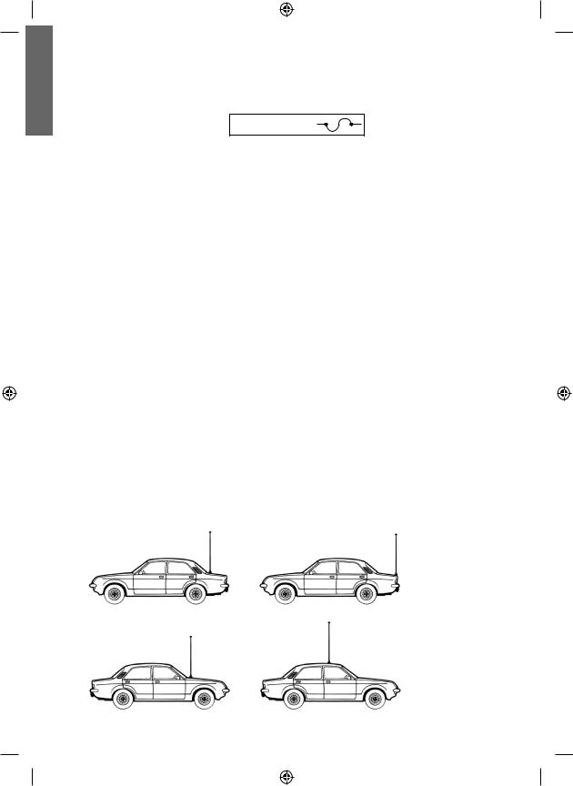
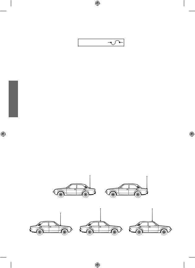
Esistono in commercio diversi tipi di antenna: con stilo a 1/4 d’onda; alimentate al centro; con carica in base; con carica in alto. Le antenne caricate sono più corte, ma per un miglior rendimento si consigliano quelle di lunghezza di circa 2 metri.
L’installazione a centro tetto è la migliore in senso assoluto perchè il ground o radiale di terra è proporzionale in tutte le direzioni, mentre su una fiancata o in una qualsiasi altra parte del veicolo, diventa proporzionale alla massa dello stesso (es: se l’antenna è installata posteriormente, diventa direttiva in avanti, cioè i segnali provenienti dalla parte opposta sono meglio ricevuti, così dicasi anche per quelli trasmessi).
N.B.: con l’ausilio di un accoppiatore a due vie, l’antenna montata anteriormente può sostiituire l’antenna della radio FM.
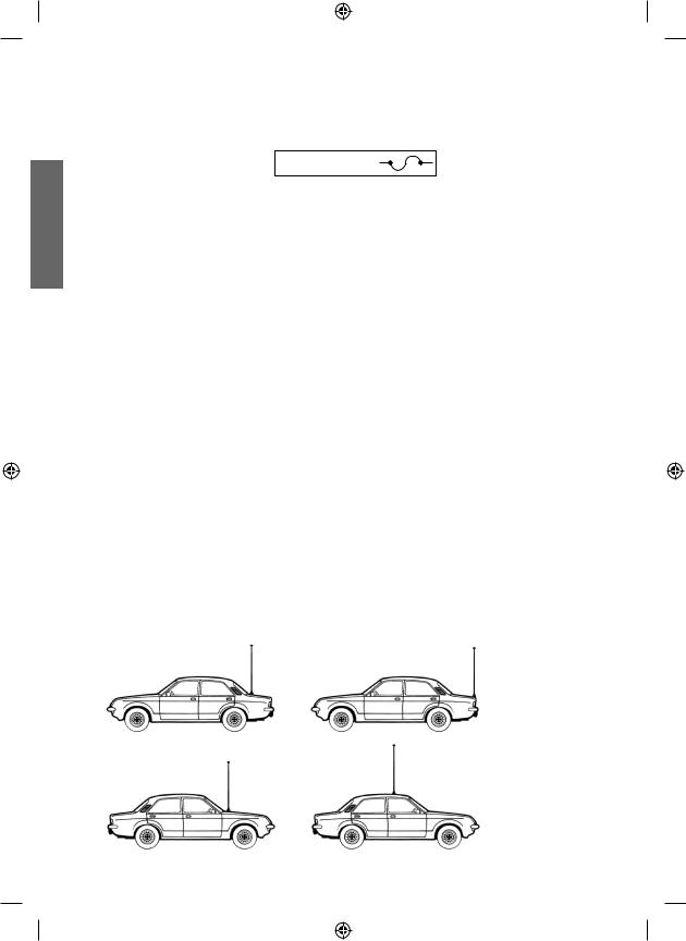
Posizioni comuni di montaggio dell’antenna
4
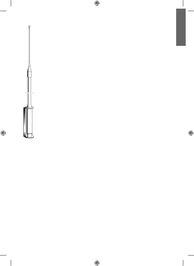
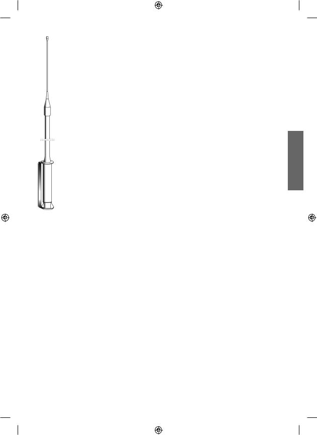
ANTENNA BASE
Per l’utilizzo del ricetrasmettitore in stazione fissa (base) occorre un alimentatore a
12-13.8 V a corrente continua 2 A. Si consiglia un’antenna 1/2 onda omnidirezionale per comunicazioni a medio e lungo raggio.
USO DEL RICETRASMETTITORE
Ricezione:
1.Assicurarsi che l’apparato sia connesso ad una corrente 12-13.8 V tramite il fusibile e il filo rosso.
2.Controllare che l’antenna e il microfono siano ben connessi.
3.Posizionare il commutatore d’emergenza sulla posizione centrale.
4.Scegliere il modo di emissione AM o FM.
5.Girare la manopola squelch nella massima posizione antioraria.
6.Accendere l’apparato mediante la manopola ON/OFF/VOL.
7.Ricercare il canale desiderato attraverso i tasti CHANNEL.
8.Regolare il volume come desiderato.
9.Regolare lo squelch. Questo comando viene utilizzato per eliminare il rumore di fondo del ricevitore in assenza di segnali d’ingresso. Per la massima sensibilità del ricevitore è preferibile che il comando sia regolato solo al preciso livello dove il rumore di fondo del ricevitore o il rumore ambientale, viene eliminato. Girare completamente in senso antiorario poi lentamente in senso orario finchè non scomparirà il rumore. Qualsiasi segnale affinchè possa venir ricevuto, dovrà essere leggermente più intenso rispetto alla media del rumore ricevuto. Un’ ulteriore rotazione in senso orario aumenterà il livello di soglia che il segnale dovrà superare per poter essere udito. Se lo squelch sarà posizionato nella massima posizione in senso orario, si potranno sentire solo segnali molto forti.
Trasmissione:
1.Selezionare il canale desiderato.
2.Premere il pulsante di trasmissione sul microfono, parlare mantenendo una distanza dalla bocca di 5/8 cm.
3.Per ricevere, rilasciare il pulsante di trasmissione.
N.B.: gridare nel microfono non aumenta la portata della trasmissione, in quanto un circuito interno automaticamente commuta la massima modulazione. Si consiglia quindi di usare un tono di voce normale.
CANALI PRIORITARI (CH 9-19)
L’ALAN 100PLUS B è dotato di un commutatore che permette di posizionarsi immediatamente sui canali 9 e 19. Il canale 9 serve solo per le comunicazioni di emergenza. Il canale 19 invece è usato per richiedere informazioni sulla viabilità, ecc.
Posizionando l’interruttore nella posizione centrale si ritornerà all’ultimo canale selezionato.
ALTOPARLANTE SUPPLEMENTARE
Inserire un altoparlante con uscita da 3-10 W nella presa EXT-SPKR. In questo modo l’altoparlante interno viene disconnesso.
ITALIANO
5

ITALIANO
CARATTERISTICHE TECNICHE
RICEVITORE
Gamma di frequenza ......................................................................................... |
da 26.965 a 27.405 |
Sensibilità ................................................................................. |
migliore di 1.0 μV per 20 dB SINAD |
Rejezione canali adiacenti ............................................................ |
60 dB (10 KHz); 70 dB (20 KHz) |
Frequenze IF .................................................................................. |
1° IF=10.7 MHz; 2° IF=455 KHz |
Potenza d’uscita audio .................................................................................................... |
4.5 W max |
Risposta in frequenza ......................................................................................... |
6 dB:450-2500 Hz |
Squelch ................................................................................................. |
regolabile da 1.2 μV a 1mV |
TRASMETTITORE
Gamma di frequenza ......................................................................................... |
da 26.965 a 27.405 |
Ciclo di utilizzo........................................................................................................................ |
5/5/90 |
Potenza d’uscita ................................................................................................................. |
4 W max |
Modulazione .......................................................................................................................... |
AM/FM |
Deviazione massima ...................................................................................... |
2.0 KHz FM; 80% AM |
Emissioni spurie ............................................................................................................. |
62 dB o più |
Tolleranza di frequenza ............................................................................................... |
più di 0.002% |
Alimentazione ......................................................................................................................... |
13.8 V |
Corrente assorbita ............................................................................................. |
FM:1.3 A; AM: 1.8 A |
Impedenza antenna ............................................................................................................. |
50 Ohm |
Dimensioni ............................................................................................................. |
124x38x190 mm |
Peso ........................................................................................................................................ |
1.2 kg |
Le specifiche sono soggette a modifiche senza preavviso.
Un dispositivo di sezionamento adatto deve essere previsto nell’impianto elettrico.
Tale dispositivo deve disconnettere entrambi i poli simultaneamente.
6

CONTENTS
Features
Installation
Replacing fuse Antenna system
Mobile antennas
Base station antenna
Using the transceiver
Remote speaker operation Technical specifications
pag. 2 pag. 3 pag. 4 pag. 4 pag. 4 pag. 5 pag. 5 pag. 6 pag. 7
ENGLISH
1

FEATURES
|
• Phase Locked Loop circuitry gives precise frequency control and stability over all 40 channels: |
||
|
|
pinpoint channel tuning accuracy with separate scan up and down controls. |
|
|
• Ceramic filters give superior selectivity and freedom from adjacent channel interference. |
||
|
• Green Led channel indicator clearly shows which channel is activated. |
||
|
• Red Led (TX) and Green Led (RX) show the operative modality: |
||
ENGLISH |
|
TX= transmission; RX=reception. |
|
• |
Hysteresis-type Squelch circuit automatically compensates for signal fading to eliminate signal |
||
|
|||
|
|
“chopping” during message reception. |
|
|
• |
Extremely sensitive. |
|
• Condenser type plug-in communications microphone provides superior transmission.
• Emergency switch lets you switch to channel 9 or 19 - instantly.
• Jacks for external speaker let you hook up other speaker systems.
• Works with negative ground 12 - 13.8 V DC.
Priority channels |
|
RX LED |
switch CH 9/19 |
LED channel display |
TX LED |
|
|
ALAN 100 PLUS |
|
40 |
TX |
|
|
|
|
9 |
|
RX |
|
|
|
CH |
|
|
|
|
|
19 |
|
|
|
|
|
FM AM |
CHANNEL |
|
|
SQUELCH |
ON/OFF VOL |
|
|
|
Microphone JACK |
SQUELCH |
Volume/Power |
AM/FM |
Channel "UP" |
Channel "DOWN" |
|
|
Switch |
switch |
switch |
switch |
|
|
|
|
External speaker jack |
|
|
|
ANT |
|
EXT |
|
|
|
|
|
|
|
|
|
|
|
SPKR |
|
|
|
|
|
+ RED |
|
|
|
|
|
- BLK |
|
2
INSTALLATION
Safetyandconveniencearetheprimaryconsiderationsformountinganypieceofmobileequipment.
All controls must be readily available to the operator without interfering with the movements necessary for safe operation of the vehicle. Be sure all cables are clear of the brake, clutch and accelerator. Also, thought must be given to the comfort of passengers.
Washer |
Nut |
|
Machine screw |
||
|
Machine screw
Washer
Hanger
Washer
Machine screw
Tapping screw
Washer
Machine screw
Another extremely important requirement is the ease of installation and removal for those occasions when you might want to remove the unit for service and maintenance.
The most common mounting position for a transceiver is under the dashboard directly over the drive shaft hump. Do not mount the transceiver in the path of the heater or air conditioning. Take your time and plan your installation carefully. When you have determined the best location for mounting, use the mounting bracket as a template to mark mounting holes.Take care when you drill the holes that you do not drill into wiring, trim or other accessories.
Mount in position with bolts, lock washers and nuts or self-threading screws.
Insert the power cable with lighter plug into the vehicle’s cigarette lighter cord.
Before operation, you must install and connect your antenna system.The lead from the antenna you’ve installed should be connected to the antenna coaxial connector. If you are using an external speaker, connect it to the EXT-SPKR jack.
EXT
ANT
SPKR +RED
-BLK
ENGLISH
3
ENGLISH
REPLACING FUSE
If you replace the fuse for DC Power Cord, use 2 A type (the one supplied as spare). Hold the fuse holder and press on the inside, then rotate the holder.
F2A 250V +
ANTENNA SYSTEM
A mobile antenna system is not limited to the antenna only. The transmission line as well as the vehicle are important factors in the total antenna system. Therefore, you must use the correct type of transmission line and mount the antenna securely in a position that will give you optimal results.
Use coaxial cable with an impedance of 50 Ohms. We suggest type RG 58/U for lengths under 2.5 m or RG 8/U for longer lengths. Generally speaking, you should keep the length of the transmission line to a minimum.
The above discussion is as important for reception as it is for the transmission. If a mismatch exists between the antenna and the receiver, the excellent sensivity and signal-to-noise radio of the receiver circuit will be defeated.
MOBILE ANTENNAS
A few general rules should help you to install any mobile antenna properly.
•Keep it as far as possible from the main bulk of the vehicle.
•During operation, it must be vertical, and rigid enough to remain vertical when the vehicle or boat is in motion.
•Mount it as far as possible from sources of noise (ignition system, gauges, etc.) and keep the transmission line away from these noise sources.
•An antenna mounted in a boat requires a good ground connection. This can be either a metal hull or a ground made of tin-foil or copper sheeting. This ground should cover an area of at least
1 m2 or more. Be sure the transceiver also has an adequate ground.
There are many types of mobile CB antennas: a full quarter-wave length whip, a centerloaded whip, top loaded whip and the base loaded type.
A vertically polarized whip antenna is best suited for mobile service. It is omni-directional.
If it’s the loaded type, you will find it a phisically shorter antenna. But, for greater efficiency the
2.5 m long, full quarter-wave whip is better. Antenna length is directly related to efficiency.
Generally, the longer it is the more efficient.
4
There are many possible antenna locations on a car. Four of the most common are shown and discussed on the following.
Roof Mount - In this position the antenna radiates equally in all directions.Since the normal 1/4 wavelength whip antenna is too long for roof mounting on a vehicle, the antenna is shortened and loading coil is used to provide the proper electrical length.
Our fiberglass roof mount is a good durable antenna.
Front Cowl Mount - The radiation pattern is slightly greater in the direction of the rear fender opposite the side on which the antenna is mounted. However, the front position offers a number of advantages. The CB antenna can be easily mounted. It can double as both the CB and the standard auto radio antenna by employng a twoway coupler. Ask about our complete line of antennas.
Rear Deck Mount - The radiation pattern is stronger in the direction of the front fender opposite the side on which the antenna is mounted. In this position you can use a full quarter-wave antenna or a shorter loaded whip. Here you might consider one of the full 2.5 meters whips.
Bumper Mount - The antenna radiates in a pattern directly in front of and to the rear of the vehicle, with maximum radiation directly away from the vehicle, in a horizontal plane. Despite its fairly irregular pattern, a bumpermounted full-length whip antenna will normally give the best results. Removing the antenna is simple and will leave no holes in the car.
BASE STATION ANTENNA
While your transceiver is designed for mobile operation, you might wish to use it as a base station unit, in conjunction with a 12 - 13.8 V 2ADC power supply. If you decide to use your transceiver as a base station, choose an antenna designed to operate
most efficiently as a base station antenna. For example, the 1/2 wave antenna is a high-efficiency radiator with omnidirectional characteristics. It performs as well in most applications as does the ground plane. You can use this type of antenna for medium-long range communications.
USING YOUR TRANSCEIVER
Do not transmit without a suitable antenna or 50 Ohm load connected to the antenna connector.
To receive:
1.Check that the unit is properly connected to a source of 12-13.8 V through the in-line fuse and red wire.
2.Make sure that the antenna is attached.
3.Connect the mic plug to the mic jack.
4.Select AM or FM mode.
5.Set the emergency switch to the center position.
6.Set the Squelch control to maximum counterclockwise position.
7.Turn on the unit by rotating the ON/OFF/VOL control.
8.Set channel selector to the desired channel.
9.Adjust the volume to a suitable listening level.
10.Adjust Squelch to cut out annoying background noise when no signal is being received.
To do this, set the Channel Selector to a channel where no signals are present or wait until signals cease on your channel. Then, rotate the Squelch control in a clockwise direction to the point where the background noise just stops. Now, when a signal is present, you will hear it,
ENGLISH
5

ENGLISH
but will not be disturbed by noise on the channel between signals.
When properly set, the Squelch keeps the receiver “dead” until a signal comes in on that channel. However, do not set the Squelch too high, otherwise weak signals will not be able to open the Squelch circuit. To receive very weak signals, it is best to leave Squelch set to the minimum position by rotating the control maximum counterclockwise. The Squelch circuit in your
Transceiver is an advanced design. It uses an operational amp IC to accomplish a hysteresis action. The result is that when you set the Squelch for a precise signal level, if that signal level increases or decreases in strength, the Squelch circuit will follow this change. With conventional Squelch circuit, often a signal which changes strength get “chopped” by the Squelch circuit and you lose a portion of the message.
With a hysteresis Squelch, you get it all.
To Transmit:
1.Select the desired channel.
2.Press the push-to talk button on the microphone and hold it an angle about 5-7 cm from your mouth and speak in a normal voice.
3.To receive, release the push-to-talk button.
Be sure the mic plug is firmly connected to the jack.
NOTE: shouting into the mic will not increase your power or signal. An internal circuit automatically sets the mic signal for maximum modulation, so speaking loudly will give no advantage.
REMOTE SPEAKER OPERATION
A 4 Ohm speaker, rated at 3-10 watts, should be used for this function. Plug the speaker into the EXT SPKR jack at the rear of the transceiver. When the external speaker is plugged in, the internal speaker is disconnected. You can now monitor all incoming signals through your remote speaker.
6

TECHNICAL SPECIFICATIONS
RECEIVER
Frequency coverage ..................................................................................... |
26.965 to 27.405 MHz |
Sensivity ................................................................................... |
better than 1.0 μV for 20 dB SINAD |
Adjacent Channel Rejection ...................................................... |
60 dB at 10 kHz; 70 dB for 20 KHz |
Intermediate Frequency ............................................................. |
1st IF=10.7 MHz; 2nd IF=455 KHz |
Audio Output power ................................................................................................... |
4.5 watts max |
Frequency Response (-6dB) ........................................................................................ |
450-2500 Hz |
Squelch ............................................................................................ |
adjustable from 1.2 μV to 1mV |
TRASMITTER
Frequency coverage ..................................................................................... |
26.965 to 27.405 MHz |
Duty cycle................................................................................................................................ |
5/5/90 |
Output Power ................................................................................................................ |
4 watts max |
Type of modulation ................................................................................................................ |
AM/FM |
Max Deviation ................................................................................................ |
2.0 KHz FM; 80% AM |
Spurious Radiation .................................................................................................... |
62 dB or better |
Frequency Tolerance .......................................................................................... |
better than 0.002% |
Antenna impedance ............................................................................................................. |
50 Ohm |
Power supply ........................................................................................................................... |
13.8V |
Current Drain .................................................................................................... |
FM: 1.3 A; AM: 1.8 A |
Dimensions ............................................................................................................ |
124x38x190 mm |
Weight ..................................................................................................................................... |
1.2 kg |
Specifications are subject to change without notice.
A readily accessible disconnect device shall be incorporated in the installation wiring. The disconnect device shall disconnect both poles simultaneously.
ENGLISH
7

INHALT |
|
Eigenschaften................................................................................................................ |
2 |
Installation und Stromanschluß...................................................................................... |
3 |
Antennen-Anschluß........................................................................................................ |
4 |
Bedienung...................................................................................................................... |
5 |
Einschalten/Lautstärke einstellen................................................................................... |
5 |
Rauschsperre (Squelch) einstellen................................................................................ |
5 |
Empfangen und Senden................................................................................................ |
5 |
Schnellschaltung für Kanal 9 und 19.............................................................................. |
6 |
Externer Lautsprecher.................................................................................................... |
6 |
Technische Daten........................................................................................................... |
7 |
DEUTSCH
1
DEUTSCH
EIGENSCHAFTEN
•PLL Schaltung zur präzisen Frequenzeinstellung und Stabilität über alle 40 Kanäle: Rastergenaue Einstellung mit Aufund Ab-Tasten .
•Keramikfilter für beste Selektivität und Nachbarkanalunterdrückung.
•Grüne LED Anzeige für die Kanalnummern.
•Rote LED (TX) und grüne LED (RX) für die Statusanzeigen: TX= Senden; RX=Empfang.
•Rauschsperre mit Hysteresis für automatische Rauschunterdrückung und optimales Schaltverhalten bei Signalfading, verhindert “abgehackte” Empfangssignale bei Empfang.
•Extrem empfindlicher Empfänger.
•Elektret-Kondensatormikrofon für beste Sendermodulationsqualität.
•Notrufund Direktkanalschalter zum schnellen Umschalten auf Kanal 9 / 19.
•Externe Lautsprecherbuchse für den Anschluß eines speziellen Funklautsprechersystems im
Fahrzeug.
•DC-Anschluss für übliche Fahrzeuge 12-13.8 V, Minuspol geerdet.
Funktion und Lage der Bedienund Anzeigenelemente
Schnellschaltung |
LED-Kanal-Display |
Empfangsanzeige, |
für Kanal 9 und 19 |
RX / Sende-Anzeige, TX |
|
ALAN 100 PLUS |
|
40 |
TX |
|
|
|
|
9 |
|
RX |
|
|
|
CH |
|
|
|
|
|
19 |
|
|
|
|
|
FM AM |
CHANNEL |
|
|
SQUELCH |
ON/OFF VOL |
|
|
|
Mikrofonbuchse |
Rauschsperre, |
Ein/Aus-Schalter, |
AM/FM |
Kanalwahl-Tasten |
|
|
Squelch |
Lautstärkeregler |
|
|
|
|
|
|
Anschluß für externen Lautsprecher, EXT |
||
|
|
ANT |
|
EXT |
|
|
|
|
|
|
|
|
|
|
|
SPKR |
|
|
|
|
+ RED |
|
|
|
|
|
- |
BLK |
|
|
Antennenbuchse, ANT (SO 239) |
Anschlusskabel zur |
|
||
|
|
|
Spannungsversorgung |
|
|
2
Installation und Stromanschluß
Sie können Ihr ALAN 100PLUS B mit der beiliegenden Mobilhalterung in Ihrem PKW befestigen.
Für die Wahl eines geeigneten Platzes müssen Sie u.a. folgende Punkte berücksichtigen: Das Gerät darf die Bedienung des PKW in keiner Weise beeinträchtigen.
Es darf die Sicherheit aller Fahrgäste in keiner Weise beeinträchtigen.
Das Gerät darf nicht über längerer Zeit direkter Sonneneinstrahlung ausgesetzt sein, da es sich sonst zu stark erwärmen könnte!
Aus dem selben Grund darf es nicht in der Nähe der Austrittsöffnungen für die Heizluft montiert werden.
Suchen Sie einen Montageort, an dem Sie das Gerät gut bedienen können!
Montage der Mobilhalterung
|
Muttern |
|
|
||
|
|
|
|
|
|
Unterlegscheiben |
Muttern |
||||
|
Federscheiben |
|
|
||
|
|
|
|
|
|
Maschinenschrauben |
|
|
|||
oder Blechschrauben |
|
|
|||
|
Rändelschraube |
|
|
||
|
Schraube |
|
|
||
|
Unterlegscheiben |
|
|
||
|
|
|
|
|
Mobilhalterung |
|
|
|
|
|
|
|
|
Unterlegscheiben |
|
|
|
Rändelschraube
Schraube
Unterlegscheiben
•Überlicherweise wird das Funkgerät unter dem Armaturenbrett montiert.
•Benutzen Sie die beiliegende Mobilhalterung als Bohrschablone und markieren Sie die beiden
Befestigungspunkte.
•Überprüfen Sie Sorgfältig, daß Sie bei der Montage an dieser Stelle keine Bauteile oder Kabel hinter dem Armaturenbrett beschädigen!
•Bohren Sie mit einem Bohrer die beiden Löcher zur Befestigung der Mobilhalterung.
•Schrauben Sie dann die Mobilhalterung mit den
beiliegenden Schrauben fest.
• Befestigen Sie das Funkgerät so in der Mobilhalterung, daß ANT die Rückseite des Funkgerätes für die weiterenAnschlüsse zugänglich bleibt.
•Stecken Sie das DC Stromkabel in die
Zigarettenanzünder-Steckdose
•Nach demAnschluß der Stromversorgung und derAntenne sowie eines eventuellen externen Lautsprechers fixieren Sie das Funkgerät in der Mobilhalterung:
•Seitliche Rändelschrauben in der gewünschten Position festziehen.
EXT
 SPKR +RED
-BLK
DEUTSCH
3
DEUTSCH
Sicherung Ersetzen
Zum Ersetzen der Sicherung im DC-Kabel verwenden Sie bitte eine 2ASicherung (Typ “F” für 250 V).
F2A 250V +
Antennen-Anschluß
Der Antennen-Anschluß ANT Ihres ALAN 100PLUS B weist eine Impedanz von 50 Ohm auf. Sie müssen eine CB-Mobilantenne mit derselben Impedanz verwenden und diese über ein Koaxialkabel (ebenfalls mit 50 Ohm Impedanz) mit der Antennenbuchse des Funkgerätes verbinden.
Bei der Wahl derAntenne spielen verschiedene Faktoren eine Rolle, lassen Sie sich hier von Ihrem
Fachhändler beraten.
Für die Leistungsfähigkeit einerAntenne ist auch der Montageort wichtig. Bitte beachten Sie hierbei folgende Punkte:
››Montieren Sie die Antenne so hoch wie möglich.
››Montieren Sie die Antenne möglichst in der Mitte einer ebenen Metallfläche.
››Montieren Sie die Antenne nicht in der Nähe interner Störquellen wie z.B. Zündanlagenoder Scheibenwischermotoren.
Der beste Platz für dieAntenne ist auf dem Fahrzeugdach. Sollte hier eine Montage schwierig sein, so gibt es auch noch andere Montagemöglichkeiten, die eine gute Abstrahlung sicherstellen.
Montieren Sie dieAntenne entweder selbst nach der dieser Antenne beiliegendenAufbauanleitung oder lassen Sie die Antenne von einem Fachmann montieren.
an der Stoßstange |
auf dem Kofferraumdeckel |
auf dem Kotflügel |
auf dem Wagendach |
auf dem Regenrinne |
4
Niemals ohne Antenne senden!
Senden Sie niemals ohne angeschlossene Antenne. Senden Sie auch dann nicht, wenn das Verbindungskabel
zwischen ALAN 100PLUS B und Antenne defekt sein sollte. Sie könnten damit die
Sender-Endstufe Ihres Funkgerätes beschädigen.
Abstimmung der Antenne
Fast alle CB-Antennen sind ab Werk auf den CB-Bereich abgestimmt. Manche CBAntennen lassen sich zusätzlich in ihrer Abstimmung optimieren. Folgen Sie hierbei der Anleitung des Antennen-Herstellers.Externer Lautsprecher. Die beste Wiedergabe erzielen Sie mit einem externen Lautsprecher, den Sie an passender Stelle in
Ihrem Fahrzeug montieren. Er wird an der rückseitigen Buchse EXT des Funkgerätes angeschlossen. Der interne Lautsprecher schaltet dann automatisch ab.
Bedienung
Einschalten/Lautstärke einstellen
In der Stellung “Off” ist Ihr ALAN 100PLUS B ausgeschaltet. Durch
Drehen des Reglers im Uhrzeigersinn wird das Gerät eingeschaltet. Weiteres Drehen im Uhrzeigersinn erhöht die Wiedergabelautstärke nach Wunsch.
Rauschsperre (Squelch) einstellen
Mit dem Regler Squelch stellen Sie die Empfangs-Signalstärke ein, ab der Sie Stationen (oder Rauschen) im Lautsprecher hören.
Steht der Regler Squelch am linken Anschlag, so ist die Rauschsperre ausgeschaltet: Auch auf einem völlig freien Kanal hören Sie im Lautsprecher Rauschen. Drehen Sie den Regler Squelch weiter im Uhrzeigersinn, so schließt die Rauschsperre. Je weiter Sie den Regler Squelch im Uhrzeigersinn drehen, umso stärker müssen die Stationen sein, die Rauschsperre zu öffnen und im Lautsprecher hörbar zu werden.
Überlicherweise stellen Sie die Rauschsperre auf die höchste Empfindlichkeit ein, so daß Sie auch bei schwachen Signalen öffnet, das allgemeine Rauschen aber nicht zu hören ist:
•Schalten Sie das CB-Funkgerät ein.
•Drehen Sie den Regler Squelch auf den linken Anschlag.
•Stellen Sie mit den Kanalwahltasten einen freien Kanal ein, auf dem nur Rauschen zu hören ist.
•Drehen Sie den Regler Squelch langsam so weit nach rechts, bis dieses Rauschen gerade verschwindet.
CB-Kanal einstellen
Den gewünschten CB-Kanal zwischen 1 und 40 stellen Sie mit dem Kanalwahltasten ein. Der aktuelle Kanal erscheint im LED-Display.
Empfangen und Senden
Normalerweise befindet sich Ihr Funkgerät im Empfangsbetrieb.
Zum Senden drücken Sie die PTT-Taste auf der linken Seite des Mikrofons. Sprechen Sie aus etwa fünf bis zehn Zentimetern Entfernung in das Mikrofon. Ihr Funkgerät befindet sich solange auf
Sendung, bis Sie die PTT-Tage des Mikrofons wieder loslassen.
Während des Sendens leuchtet die Sende-Anzeige.
DEUTSCH
5

DEUTSCH
Schnellschaltung für Kanal 9 und 19
Ihr ALAN 100PLUS B verfügt über eine Schnellschaltung, mit der Sie sofort die Anrufkanäle 9 oder
19 aufrufen können.
Diese Umschaltung wird mit Schiebeschalter „9 CH 19“ vorgenommen.
•In Position 9 (oben) schaltet das Funkgerät sofort auf Kanal 9.
•In Position 19 (unten) schaltet das Funkgerät sofort auf Kanal 19.
•In Position CH (Mitte) können Sie mit den Tasten UP/DOWN einen beliebigen Kanal zwischen 1 und 40 einstellen.
Hinweis: Die UP/DOWN Tasten sind gesperrt, wenn der Schalter auf Postion 9 oder 19 gestellt ist.
Externer Lautsprecher
Im ALAN 100PLUS B ist bereits ein Lautsprecher eingebaut. Sie können aber auch einen externen
Lautsprecher einsetzen und diesen an einer akustisch günstigen Stelle im Auto montieren.
Der externe Lautsprecher wird an der Buchse EXT angeschlossen. Dabei schaltet sich der interne Lautsprecher
automatisch ab.
Der externe Lautsprecher muß eine Impedanz von 4-8.Ohm und eine Belastbarkeit von min. 3 Watt aufweisen. Der Anschluß erfolgt über einen 3,5 mm Klinkenstecker
6
Technische Daten
Empfänger
Frequenzbereich.............................................................................................. |
26,965 - 27,405 MHz |
Empfindlichkeit ............................................................................. |
besser als 1µV bei 20 dB SINAD |
Zwischenfrequenzen ............................................................... |
1. ZF: 10,695 MHz - 2. ZF: 455 kHz |
NF-Wiedergabeleistung ................................................................................................. |
max. 4,5 W |
Modulationsfrequenzgang ..................................................................................... |
450 Hz - 2,5 kHz |
Sender
Frequenzbelegungsdauer........................................................................................................ |
5/5/90 |
HF-Sendeleistung ...................................................................................................................... |
4W |
Modulation.............................................................................................................................. |
AM/FM |
Betriebsspannung .................................................................................................. |
nom. 13,8 V DC |
Stromaufnahme .................................................................................................. |
FM:1.3A; AM: 1.8A |
Abmessungen ......................................................................................... |
124x38x190 mm (BxHxT) |
Gewicht .................................................................................................................................. |
1,2 kg |
Abweichungen von den Technischen Daten im Zuge der Weiterentwicklung bleiben vorbehalten.
Direkter Anschluss des Gerätes an DC Netze ist nur über eine entsprechende Sicherung zulässig.
DEUTSCH
7
 Loading...