


 Loading...
Syn-Tech III P25 Portable Radio
OPERATION MANUAL
Midland
Syn-Tech III P25
Portable Radio
OPERATION MANUAL
680-090-2041 Version 5.0
http://www.midlandradio.com

Syn-Tech III P25 Portable Radio
OPERATION MANUAL
PREFACE
Thank you for purchasing a Midland Syn-Tech III P25 Portable Radio. Properly used, this product will give you many years of reliable service. To get the most out of your purchase, be sure to carefully read this manual and keep it on hand for later reference when needed.
Before installing and using your radio, please read this operation manual.
CUSTOMER ASSISTANCE
Should you encounter any problems with this product, or are unable to use its features, please review this operation manual. If you require further assistance after reading this manual, please contact your local dealer.
FOR WARRANTY, PRODUCT SERVICE AND ACCESSORY INFORMATION
Please contact your local dealer or distributor.
Do not attempt to service any internal parts yourself. This radio should be opened by authorized personnel only.
Your radio is packed and labeled according to the commercial packaging standards.
680-090-2041 |
i |
Version 5.0 |
http://www.midlandradio.com |
|

Syn-Tech III P25 Portable Radio
OPERATION MANUAL
IMPORTANT SAFETY INFORMATION
Before using your radio, please read this operation manual.
GENERAL PRECAUTIONS
Always use only Midland authorized accessories.
Unauthorized accessories have the risk of fire hazard, explosion, personal injury or damage to the radio.
CAUTION
Changes or modifications to your radio may void its compliance with government laws/rules and make it illegal to use.
Avoid using the radio at temperatures below -30ºC or above 60ºC. Avoid storing the radio at temperatures below -40ºC or above 85ºC.
WARNINGS
Your Midland Syn-Tech III P25 Portable Radio generates electromagnetic RF energy when it is transmitting. To ensure that you and those around you are not exposed to excessive amounts of that energy (beyond recommended allowable limits for occupational use):
DO NOT operate your radio without a proper antenna. Transmitting without an antenna may damage your radio.
DO NOT touch the antenna, or allow the antenna to touch any bystanders, when you are transmitting.
DO NOT attempt to service any internal parts yourself. Please ask your dealer for necessary service. This radio should be opened by authorized personnel only.
Please read the installation and operating instructions carefully.
680-090-2041 |
ii |
Version 5.0 |
http://www.midlandradio.com |
|

Syn-Tech III P25 Portable Radio
OPERATION MANUAL
FCC EXPOSURE STATEMENTS
WARNINGS
The FCC has adopted a safety standard for human exposure to RF energy. Proper operation of this radio under normal conditions results in user exposure to RF energy below the Occupational Safety and Health Act and Federal Communication Commission limits.
This radio is NOT approved for use by the general population in an uncontrolled environment. This radio is restricted to occupational use, work related operations only, where the radio operator must have the knowledge to control the user’s exposure conditions for satisfying the higher exposure limit allowed for occupational use.
When transmitting, hold the radio in a vertical position with its microphone 2 inches (5 cm) away from your mouth. The radio is transmitting when the red Transmit/Receive LED on the top of the radio is illuminated. You can cause the radio to transmit by pressing PTT on the side of the radio.
DO NOT operate the radio without the proper antenna installed. Do not substitute any antenna for the one supplied or recommended by the manufacturer or radio dealer. By not following the antenna recommendations you may be exposing person(s) to excess radio frequency radiation. You may contact your radio dealer or the manufacturer for further information.
DO NOT transmit more than 50% of total radio use time (50% duty cycle). Transmitting for more than 50% of the time can cause FCC RF exposure compliance requirements to be exceeded. This radio is transmitting whenever the Transmit/Receive LED is red. Pressing the PTT switch on the side of the radio normally causes the radio to transmit.
DO NOT allow the antenna to touch any part of your body while transmitting. DO NOT transmit while the radio is attached to your belt.
KEEP the radio and antenna at least as far from bystanders as from yourself.
The preceding information is provided to make you aware of RF exposure and how to ensure that this radio is operated within FCC RF exposure limits.
PATENT AND COPYRIGHT STATEMENTS
The AMBE+2™ voice coding Technology embodied in this product is protected by intellectual property rights including patent rights, copyrights and trade secrets of Digital Voice Systems, Inc. This voice coding Technology is licensed solely for use within this Communications Equipment. The user of this Technology is explicitly prohibited from attempting to extract, remove, decompile, reverse engineer of disassemble the Object Code, or in ay other way convert the Object Code into a human readable form. U.S. Patents Nos. #5,870,405, #5826,222, #5,754,974, #5,701,390, #5,715,365, #5,649.050, #5,630,011, #5,581,656, #5,517,511, #5,491,772, #5,247,579, #5,226,084, and #5,195,166
680-090-2041 |
iii |
Version 5.0 |
http://www.midlandradio.com |
|

Syn-Tech III P25 Portable Radio
OPERATION MANUAL
PRODUCT FEATURES
Your Midland Syn-Tech III P25 Portable Radio has the following features:
•136-174 MHz VHF and 380-470 MHz UHF bands
•Mixed analog and digital mode operation
•Easy installation
•Low maintenance
•Tri-color LCD display
•Full keypad
•High quality audio
•User friendly interface
•Extensive user prompts, alerts and warnings
•Flexible accessory connections
•Microprocessor controlled
•DSP based audio
•Flash memory
•Synthesized frequency control
•Extensive use of surface mount technology
•PC controlled testing and alignment
•CTCSS/CDCSS sub-audible signaling
•2-Tone / 5-Tone analog signaling
•Analog DTMF encoding
•Conforms with TIA/EIA-603-A standard in Analog Mode
•Conforms with TIA/EIA-102-CAAB standard in Digital Mode
•Conforms with APCO25 EIA / TIA 102 standards
•Conforms with MIL-STD-810E standards
Full technical specifications are given near the back of this manual.
680-090-2041 |
iv |
Version 5.0 |
http://www.midlandradio.com |
|

Syn-Tech III P25 Portable Radio
OPERATION MANUAL
|
ABBREVIATIONS AND ACRONYMS |
ACK |
: Acknowledge |
AES |
: Advanced Encryption Standard |
ALG |
: Algorithm |
ANI |
: Automatic Number Identification |
dBm |
: Decibel Milliwatt |
CIK |
: Crypto Ignition Key Identity |
CDCSS : Continuous Digital Coded Squelch System |
|
CTCSS |
: Continuous Tone Controlled Squelch System |
DCS |
: Digital Coded Squelch |
DES |
: Data Encryption Standard |
DSP |
: Digital Signal Processing |
GPS |
: Global Positioning System |
ID |
: Identity |
LCD |
: Liquid Crystal Display |
MSG |
: Message |
NAC |
: Network Access Code |
RF |
: Radio Frequency |
RSSI |
: Received Signal Strength Indicator |
RX |
: Receive |
SC |
: Selective Call |
TCS |
: Tone Coded Squelch |
TBX |
: Telephone Branch Exchange |
TX |
: Transmit |
WACN |
: Wide Area Communication Network |
680-090-2041 |
v |
Version 5.0 |
http://www.midlandradio.com |
|

|
|
|
Syn-Tech III P25 Portable Radio |
|
|
|
|
OPERATION MANUAL |
|
|
|
|
TABLE OF CONTENTS |
|
1 |
INTRODUCTION...................................................................................................... |
1 |
||
|
1.1 |
Package Contents........................................................................................... |
1 |
|
2 |
GETTİNG STARTED ............................................................................................... |
2 |
||
|
2.1 |
Installing the Antenna...................................................................................... |
2 |
|
|
2.2 |
Installing and Removing the Battery................................................................ |
2 |
|
|
|
2.2.1 |
Installing the Battery ........................................................................... |
2 |
|
|
2.2.2 |
Removing the Battery ......................................................................... |
2 |
|
2.3 |
Installing the Belt Clip...................................................................................... |
3 |
|
|
2.4 |
Charging the Battery ....................................................................................... |
3 |
|
3 RADİO CONTROLS AND INDİCATORS................................................................. |
4 |
|||
|
3.1 |
Side, Top and Front Views.............................................................................. |
4 |
|
|
3.2 |
Button and Key Functions ............................................................................... |
5 |
|
|
|
3.2.1 |
Channel Switch................................................................................... |
5 |
|
|
3.2.2 |
Emergency Call Button ....................................................................... |
5 |
|
|
3.2.3 |
Alpha-Numeric keypad........................................................................ |
5 |
|
|
3.2.4 |
Up/Down keys..................................................................................... |
5 |
|
|
3.2.5 |
Left soft key (Menu) ............................................................................ |
5 |
|
|
3.2.6 |
Right soft key (Index).......................................................................... |
6 |
|
|
3.2.7 |
Power Adjust (long press)/Mode Change (short press) key................ |
6 |
|
|
3.2.8 |
Monitor (long press)/Call Wait Option (short press) key...................... |
6 |
|
|
3.2.9 |
Keypad Lock (short press)/Emergency Reset (long press) key .......... |
6 |
|
|
3.2.10 |
Scan key............................................................................................. |
7 |
|
|
3.2.11 |
Star key............................................................................................... |
7 |
|
|
3.2.12 |
Pound key........................................................................................... |
8 |
|
3.3 |
Alpha-numeric Keypad Entry......................................................................... |
10 |
|
|
3.4 |
Display Icons................................................................................................. |
11 |
|
4 |
OPERATION |
.......................................................................................................... |
13 |
|
|
4.1 |
Basic Operation............................................................................................. |
13 |
|
|
|
4.1.1 |
Turning the Radio On and Off........................................................... |
13 |
|
|
4.1.2 |
Selecting Zones ................................................................................ |
14 |
|
|
4.1.3 |
Selecting Channels........................................................................... |
16 |
|
|
4.1.4 |
Receiving Signals ............................................................................. |
17 |
|
|
4.1.5 |
Transmitting to Other Radios ............................................................ |
18 |
|
|
4.1.6 |
Selecting Transmit Power ................................................................. |
21 |
|
|
4.1.7 |
Selecting Digital Talk Group ............................................................. |
22 |
|
|
4.1.8 |
Selecting Talkaround Transmit Mode ............................................... |
24 |
|
|
4.1.9 |
Monitoring Channels......................................................................... |
25 |
|
|
4.1.10 |
Selecting Digital Call Wait Option ..................................................... |
27 |
|
|
4.1.11 |
Scanning Channels........................................................................... |
28 |
|
|
4.1.12 |
Locking the Keypad .......................................................................... |
31 |
|
|
4.1.13 |
Switching to the Home Zone and Channel........................................ |
32 |
|
4.2 |
Advanced Operations.................................................................................... |
33 |
|
680-090-2041 |
vi |
|
||
Version 5.0 |
|
|
|
|
http://www.midlandradio.com

|
|
|
Syn-Tech III P25 Portable Radio |
|
|
|
|
OPERATION MANUAL |
|
|
|
4.2.1 |
Receiving Emergency Calls .............................................................. |
33 |
|
|
4.2.2 |
Transmitting Emergency Calls .......................................................... |
34 |
|
|
4.2.3 |
Receiving Digital Individual Calls ...................................................... |
35 |
|
|
4.2.4 |
Transmitting Digital Individual Calls .................................................. |
37 |
|
|
4.2.5 |
Transmitting Digital Unaddressed Calls............................................ |
39 |
|
|
4.2.6 |
Transmitting Digital Telephone Interconnect Calls............................ |
40 |
|
|
4.2.7 |
Receiving a Digital Call Alert............................................................. |
41 |
|
|
4.2.8 |
Transmitting a Digital Call Alert......................................................... |
41 |
|
|
4.2.9 |
Receiving and Sending Non-voice Messages................................... |
42 |
|
|
4.2.10 |
Channel Programming...................................................................... |
50 |
|
4.3 |
Menu Operation ............................................................................................ |
51 |
|
|
|
4.3.1 |
Analog Mode Menu Tree .................................................................. |
51 |
|
|
4.3.2 |
Digital Mode Menu Tree.................................................................... |
53 |
5 |
ACCESSORIES ..................................................................................................... |
56 |
||
6 |
STORAGE AND CLEANING PRECAUTIONS...................................................... |
57 |
||
7 |
TROUBLESHOOTING........................................................................................... |
58 |
||
8 |
SPECIFICATIONS ................................................................................................. |
59 |
||
|
8.1 |
Receiver Specifications................................................................................. |
61 |
|
|
8.2 |
Transmitter Specifications............................................................................. |
62 |
|
9 |
WARRANTY STATEMENT ................................................................................... |
63 |
||
680-090-2041 |
vii |
Version 5.0 |
http://www.midlandradio.com |
|
Syn-Tech III P25 Portable Radio
OPERATION MANUAL
1 INTRODUCTION
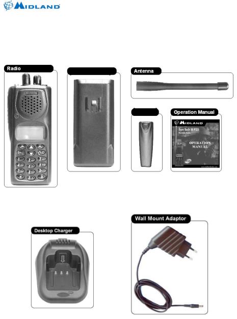
1.1Package Contents
The following items are in your Midland Syn-Tech III P25 Portable Radio package:
Li-Ion Battery
Belt Clip |
The desktop charger and wall adaptor are sold separately:
680-090-2041 |
1 |
Version 5.0 |
http://www.midlandradio.com |
|
2 Getting Started
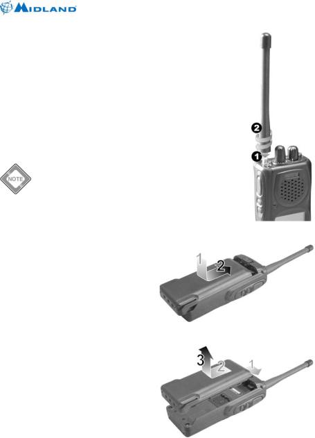
2.1Installing the Antenna
The antenna should be attached to your radio before use. Using your radio without the antenna may damage the radio.
1.Align the base of the antenna with the socket on the top of the radio.
2.Screw it all the way into the socket. Be sure that antenna seats properly.
2.2Installing and Removing the Battery
The battery should be charged before use. The battery may be charged while installed or removed from the radio.
2.2.1Installing the Battery
1.With the belt clip facing up and LCD facing down, position the battery leaving approximately ½ inch space between the top of the battery and the battery latch.
Three mating clips help you to align the battery.
2.Slide the battery all the way up to the battery latch, until you feel and hear a click.
2.2.2Removing the Battery
1.With the belt clip facing up and LCD facing down, push the battery latch to the right until it stops.
2.Slide the battery away from the latch about ½ inch.
3.Separate the battery from the radio by lifting up, away from the radio.
Syn-Tech III P25 Portable Radio
OPERATION MANUAL
Figure 2.1 – Installing the Antenna
Figure 2.2 – Installing the battery
Figure 2.3 – Removing the battery
680-090-2041 |
2 |
Version 5.0 |
http://www.midlandradio.com |
|
Syn-Tech III P25 Portable Radio
OPERATION MANUAL
2.3 Installing the Belt Clip
1. Pinch the belt clip mounting bracket using your thumb and index finger.
2. Align the belt clip mounting bracket with the slots on the battery.
3. Press the belt clip against the battery and slide the clip fully into the retaining slots.
2.4 Charging the Battery
Figure 2.4 – Installing the belt clip
CAUTION
The Li-Ion rechargeable battery should only be charged using Midland authorized desktop chargers.
To charge the battery:
1.Insert the wall mount adaptor cord into the back of the drop-in charging cradle.
2.Plug the other end of the wall mount adaptor into the appropriate AC power source.
3.Place the radio into the desktop charger. The metal pads on the radio must contact the mating pads in the charger.
4.Observe that the red light on the front of the charger glows red to indicate that the radio is properly seated and the charger is operating in fast charge mode.
5.Allow the batteries to charge for 12 to 15 hours for initial charge.
CAUTION
The charger is only designed to charge the battery, not power the radio. You can monitor incoming calls while the radio is charging. However, you should always remove the radio from the charger before transmitting.
WARNING
The LED on the front of the charger glows green after 4 hours to indicate the radio is fully charged. However, you should leave your radio in the charger 12 to 15 hours for initial charge.
WARNING
See troubleshooting near the end of this manual for additional desktop charger LED alerts.
As you use your radio, the battery level icon will show the battery power remaining. When the icon shows empty (no bars), it is time to recharge the battery.
680-090-2041 |
3 |
Version 5.0 |
http://www.midlandradio.com |
|

Syn-Tech III P25 Portable Radio
OPERATION MANUAL
3 Radio Controls and Indicators
3.1Side, Top and Front Views
680-090-2041 |
4 |
Version 5.0 |
http://www.midlandradio.com |
|

Syn-Tech III P25 Portable Radio
OPERATION MANUAL
3.2Button and Key Functions
Below is a brief description of each button or key. For more details of each function refer to the operation section of this manual. Many of the functions may be disabled by radio programming or unavailable because of the current analog/digital mode selection. Many of the buttons have a short press, or press and release function, and a long press, or press and hold function. The short press is function is performed if the button is pressed for less than one second, and the long press function is performed if the button is pressed for more than one second.
3.2.1Channel Switch
The channel switch provides direct access to channels 1-15 in the current zone. In the sixteenth position, the up/down and direct channel entry modes are available. If the channel switch is in the sixteenth position, the radio will power on to last selected channel. In any other position, the radio will power on to the switch-selected channel.
3.2.2 Emergency Call Button
The emergency button initiates emergency mode. The emergency function is only available in digital mode. The emergency key must be pressed for five seconds to activate the emergency function. Once emergency mode is activated, the radio will switch to emergency channel and initiate five SBC emergency transmissions. The emergency bit will be set on all user initiated digital transmissions until the emergency is cleared by a long press of the keypad lock key or the radio is turned off.
3.2.3Alpha-Numeric keypad
The alpha-numeric keypad provides direct channel select from standby mode. The alpha-numeric keypad also generates DTMF tones while PTT is pressed on analog channels and enters alpha-numeric characters within other functions.
3.2.4Up/Down keys
The up/down keys provide up/down channel select from standby mode. The up/down keys are generally used to scroll through lists within other functions.
3.2.5 Left soft key (Menu)
The left soft key enters the menus from standby mode. The left soft key is generally used as SELECT or OK within other functions.
680-090-2041 |
5 |
Version 5.0 |
http://www.midlandradio.com |
|

Syn-Tech III P25 Portable Radio
OPERATION MANUAL
3.2.6 Right soft key (Index)
The right soft key accesses the index (20 unit address book) from standby mode. Once the appropriate ID is displayed, press SELECT to edit the entry or # to initiate an acknowledged individual call to the displayed unit. Up to six of the first entries may be predefined in radio programming and may not be editable. Individual call initiation may be disabled by radio programming.
The right soft key is generally used as EXIT within other functions. The right soft key is used a nuisance channel delete during scan.
3.2.7 Power Adjust (long press)/Mode Change (short press) key
A long press of this key changes the transmit power level. The selections are high, medium and low power. A default power level is set each time the channel is selected.
A short press of this key changes the transmit mode on multi-mode and digital channels. The selections may include analog, digital clear, and digital encrypted transmit modes. A default mode is set each time the channel is selected.
3.2.8Monitor (long press)/Call Wait Option (short press) key
A long press of this key turns monitor on. The function of the monitor button depends on digital/analog/mixed mode and the radio programming. If monitor is enabled the monitor function may disable the squelch on analog and mixed channels. The monitor function may allow all NACs and talk groups to be received on digital and mixed channels. While monitor is on, a long press of the Monitor/Call Wait key turns monitor off.
A short press of this key turns the call wait option on. The call wait option is available only on digital channels. When the call wait option is on, all normal group calls will be muted. If an individual call or all call is received, the call will be heard and the call wait option will be canceled. While call wait is on, a short press of the Monitor/Call Wait key turns call wait off.
3.2.9 Keypad Lock (short press)/Emergency Reset (long press) key
A short press of this key initiates keypad lock. While the keypad is locked, a short press of the Keypad Lock/Emergency Reset key will initiate keypad unlock mode.
680-090-2041 |
6 |
Version 5.0 |
http://www.midlandradio.com |
|

Syn-Tech III P25 Portable Radio
OPERATION MANUAL
While the emergency function is active, a long press of the Keypad Lock/Emergency Reset key will cancel the emergency mode.
3.2.10 Scan key
A short press of this key turns on selectable priority scan. Selectable priority scan assigns the selected channel as the high priority channel. A second, lower priority channel may be assigned in radio programming. All channels in the selected zone’s scan list will be scanned. If PTT is pressed while scanning, the radio will transmit on the high priority channel. If PTT is pressed while scan is paused on a channel the radio will transmit on the pause channel. If MENU is pressed scan is canceled. While scan is on, a short press of the Scan key cancels scan.
The Scan key is also used as a clear (long press) or backspace (short press) key during alpha-numeric keypad entry.
3.2.11 Star key
The key is a multi-function key allowing selection of several functions with successive presses. The available functions depend on analog/digital mode. In digital mode the talk group select, all call, talkaround and home functions may be available. In analog mode the talkaround and home functions may be available.
3.2.11.1Switching Talk Group
The first press of the key may prompt “GROUP:” to enter a new talk group. This function is only available in digital mode and the entered talk group must be in the selected zone’s talk group list.
3.2.11.2Entering/Exiting Unaddressed Voice Call Mode
Successive presses of the key may prompt “ENTER TO UNADDRESSED VOICE CALL?” or “EXIT UNADDRESSED VOICE CALL?” to enter/exit unaddressed voice call mode. This function is only available in digital mode. Unaddressed Voice Call mode implements an all call function to all talk groups using the channel.
Transmitting unaddressed calls may be disabled by radio programming.
3.2.11.3Entering/Exiting Talkaround Mode
Successive presses of the key may prompt “ENTER TO TALKAROUND MODE?” or “EXIT TALKAROUND MODE?” to enter/exit talkaround mode. This option is not available on simplex (direct) channels. The talkaround function sets the transmitter to the programmed receive frequency/CTCSS/DCS/NAC.
680-090-2041 |
7 |
Version 5.0 |
http://www.midlandradio.com |
|

Syn-Tech III P25 Portable Radio
OPERATION MANUAL
3.2.11.4Switching to Home Zone and Channel
Successive presses of the key may prompt “GO TO HOME?” to switch to the home zone and channel.
3.2.12 Pound key
The # key is a multi-function key allowing selection of several functions with successive presses. The available functions depend on analog/digital mode. In digital mode the zone select, status set, individual call, telephone call and call alert functions may be available. In analog mode the zone select, selective call and two tone call functions may be available.
3.2.12.1Switching Zones
The first press of the # key may prompt “ZONE NO:” to switch zones. The up/down keys will scroll through the available zones. The left soft key selects the displayed zone and the right soft key exits without changing zones.
3.2.12.2Setting Current Status
Successive presses of the # key may prompt “CUR. STATUS:” to set the current status. This function is only available in digital mode. The current status is used when sending status to other users, or when other users request the current status. The current status may also be set under MENU | STATUS | PRESENT STATUS.
Sending current status and requesting status from other users may be disabled in radio programming. You may still set current status and receive status messages from other users.
3.2.12.3Entering Unacknowledged Individual Call Mode
Successive presses of the # key may prompt “INDIVIDUAL:” to enter unacknowledged individual call mode. This function is only available in digital mode. A unit ID may be entered or selected from the index list. Once a unit ID is selected, the radio will enter individual call mode. The radio will transmit unit to unit calls to the entered unit ID each time PTT is pressed. If PTT is not pressed and no signal is received the individual call mode will time out after ten seconds.
Individual calling may be disabled by radio programming.
3.2.12.4Initiating a Telephone Interconnect Request
Successive presses of the # key may prompt “TELEPHONE:” to initiate a telephone call. This function is only available in digital mode. This function initiates a telephone interconnect request on the RF subsystem.
680-090-2041 |
8 |
Version 5.0 |
http://www.midlandradio.com |
|

Syn-Tech III P25 Portable Radio
OPERATION MANUAL
Telephone calling may be disabled or the number of dial digits may be limited by radio programming.
3.2.12.5Sending a Call Alert
Successive presses of the # key may prompt “CALL ALERT:” to initiate a call alert transmission. This function is only available in digital mode.
Call alert transmissions may be disabled by radio programming.
3.2.12.6Transmitting a Selective Call
Successive presses of the # key may prompt “SELECTIVE CALL” to transmit a selective call. This function is only available in analog mode.
Selective calling may be disabled by radio programming.
3.2.12.7Transmitting a 2-Tone Call
Successive presses of the # key may prompt “TWO-TONE CALL” to transmit a 2-tone call. This function is only available in analog mode.
Two-tone calling may be disabled by radio programming.
680-090-2041 |
9 |
Version 5.0 |
http://www.midlandradio.com |
|

Syn-Tech III P25 Portable Radio
OPERATION MANUAL
3.3Alpha-numeric Keypad Entry
The keypad is used to enter alpha-numeric characters within many functions. When the radio is in alpha-numeric mode, successive presses (less than one second apart) of the keys will step through the available characters. Pausing for more than a second will accept the displayed character and move the cursor right one space. A short press of the Scan/Clear key deletes the previous character and move the cursor left one space. A long press of the Scan/Clear key returns the radio to standby mode.
Table 2: Alpha-numeric Keypad Entry
Keys |
|
|
|
Number of Key Presses |
|
|
|
|
||||
|
|
|
|
|
|
|
|
|
|
|
|
|
|
1 |
2 |
3 |
4 |
5 |
6 |
7 |
|
8 |
9 |
10 |
11 |
|
|
|
|
|
|
|
|
|
|
|
|
|
1 |
Space |
1 |
|
|
|
|
|
|
|
|
|
|
|
|
|
|
|
|
|
|
|
|
|
|
|
2 |
A |
B |
C |
2 |
a |
b |
c |
|
Ç |
ç |
|
|
|
|
|
|
|
|
|
|
|
|
|
|
|
3 |
D |
E |
F |
3 |
d |
e |
f |
|
|
|
|
|
|
|
|
|
|
|
|
|
|
|
|
|
|
4 |
G |
H |
I |
4 |
g |
h |
i |
|
Ğ |
ğ |
İ |
I |
|
|
|
|
|
|
|
|
|
|
|
|
|
5 |
J |
K |
L |
5 |
j |
k |
l |
|
|
|
|
|
|
|
|
|
|
|
|
|
|
|
|
|
|
6 |
M |
N |
O |
6 |
m |
n |
o |
|
Ö |
ö |
|
|
|
|
|
|
|
|
|
|
|
|
|
|
|
7 |
P |
Q |
R |
S |
7 |
p |
q |
|
r |
s |
Ş |
ş |
|
|
|
|
|
|
|
|
|
|
|
|
|
8 |
T |
U |
V |
8 |
t |
u |
v |
|
Ü |
ü |
|
|
|
|
|
|
|
|
|
|
|
|
|
|
|
9 |
W |
X |
Y |
Z |
9 |
w |
x |
|
y |
z |
|
|
|
|
|
|
|
|
|
|
|
|
|
|
|
0 |
0 |
+ |
. |
, |
: |
; |
! |
|
” |
’ |
|
|
|
|
|
|
|
|
|
|
|
|
|
|
|
|
* |
/ |
\ |
- |
( |
) |
@ |
|
|
|
|
|
|
|
|
|
|
|
|
|
|
|
|
|
|
|
# |
? |
€ |
$ |
% |
& |
< |
|
= |
> |
|
|
|
|
|
|
|
|
|
|
|
|
|
|
|
680-090-2041 |
10 |
Version 5.0 |
http://www.midlandradio.com |
|
Syn-Tech III P25 Portable Radio
OPERATION MANUAL
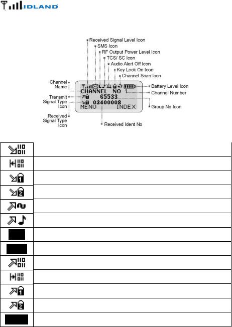
3.4Display Icons
Table 1: Display Icons
This Digital Receive icon appears when a clear (unencrypted) digital signal is received.
This Digital Talkaround Receive icon appears when a clear digital signal is received in direct or talkaround mode.
This Digital Encryption 1 Receive icon appears when an encrypted digital signal using the first encryption algorithm is received.
This Digital Encryption 2 Receive icon appears when an encrypted digital signal using the second encryption algorithm is received.
This Analog Transmit icon appears when the radio is set to transmit in analog mode.
This CTCSS Transmit icon appears when the radio is set to transmit in analog mode with CTCSS.
This CDCSS Transmit icon appears when the radio is set to transmit in analog mode with CDCSS.
This Analog Talkaround Transmit icon appears when the radio is set to transmit in analog talkaround mode.
This Digital Transmit icon appears when the radio is set to transmit in clear digital mode.
This Digital Talkaround Transmit icon appears when the radio is set to transmit in digital talkaround mode.
This Digital Encryption 1 Transmit icon appears when the radio is set to transmit in digital encrypted mode using the first encryption algorithm.
This Digital Encryption 2 Transmit icon appears when the radio is set to transmit in digital encrypted mode using the second encryption algorithm.
This Received Signal Level icon appears when a signal is being received. The number of bars indicates the relative signal strength.
680-090-2041 |
11 |
Version 5.0 |
http://www.midlandradio.com |
|

Syn-Tech III P25 Portable Radio
OPERATION MANUAL
This SMS icon appears after an SMS is received and remains on until the message is read.
This High Power icon appears when high transmit power level is selected. This Mid Power icon appears when medium transmit power level is selected. This Low Power icon appears when low transmit power level is selected.
This Tone Squelch icon appears when channel is set to receive a CTCSS or CDCSS signal.
This Call Wait icon appears when digital call wait mode is selected. This Alert Tones Off icon appears when alert tones are disabled. This Keypad Lock icon appears when keypad lock is selected. This Scan icon appears when scan is selected.
This Battery Level icon appears when a Midland rechargeable battery pack is installed.
680-090-2041 |
12 |
Version 5.0 |
http://www.midlandradio.com |
|
Syn-Tech III P25 Portable Radio
OPERATION MANUAL
4 OPERATION
4.1Basic Operation
Despite the radio’s advanced feature set, the basic receive and transmit operations can still be quite simple. The radio is capable of distinguishing between analog and digital signals, and the channel may be configured to receive both signal types with no user intervention. The radio channel may also be configured to allow users to transmit analog signals, digital signals, or choose the appropriate transmit mode.
4.1.1Turning the Radio On and Off
Rotate the On/Off Volume Knob clockwise past the detent to turn the radio on. Rotate the knob further clockwise to increase the speaker volume. Rotate the knob counter-clockwise to decrease the speaker volume. Rotate the knob counter-clockwise past the detent to turn the radio off.
While the radio is performing power-on selftests, it will display the greeting message and the current zone selection. If the channel switch is in the sixteenth position, the radio will poweron to the last selected channel. In any other position the radio will power-on to the switchselected channel.
Figure 4.1 – On/Increase Volume
Figure 4.2 –Off/Decrease Volume
If a power-on password has been |
|
|
|
|
|
|
|
|
|
set, the radio will prompt for |
|
|
|
|
password entry when it is turned on. |
|
|
|
|
Use the numeric keypad to enter the |
Enter 5 |
|
|
|
correct password then press the left |
digit |
|
|
|
|
|
|||
soft key (OK). If the password is |
password |
|
|
|
entered incorrectly five times, the |
|
|
|
|
radio will lock and must be |
|
|
|
|
reprogrammed to reset the |
|
|
|
|
password. |
Press OK |
|
|
|
|
|
|
|
|
|
to |
|
|
|
|
|
|
|
|
|
continue |
|
|
|
|
|
|
|
|
|
|
|
|
|
|
|
|
|
|
Figure 4.3 – Power-on password entry
680-090-2041 |
13 |
Version 5.0 |
http://www.midlandradio.com |
|
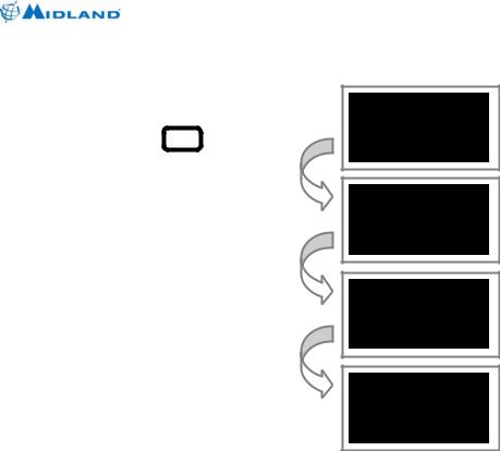
4.1.2Selecting Zones
The radio channels may be organized into zones or channel groupings to sort and organize the channels. To
select a new zone, press the  (pound) key, then use the Up/Down keys to scroll through the available zones. The new zone number may also be entered using the keypad.
Press the left soft key (OK) to switch to the new zone. The first channel in the new zone will be displayed.
Syn-Tech III P25 Portable Radio
OPERATION MANUAL
Press #
key
Use up/down to select new zonel
Press OK to select new zone
Figure 4.4 – Zone selection using # key
680-090-2041 |
14 |
Version 5.0 |
http://www.midlandradio.com |
|
Loading...