


UR-BC93CM-ST
Service Manual, 2016-12
1 / 37
Service Manual
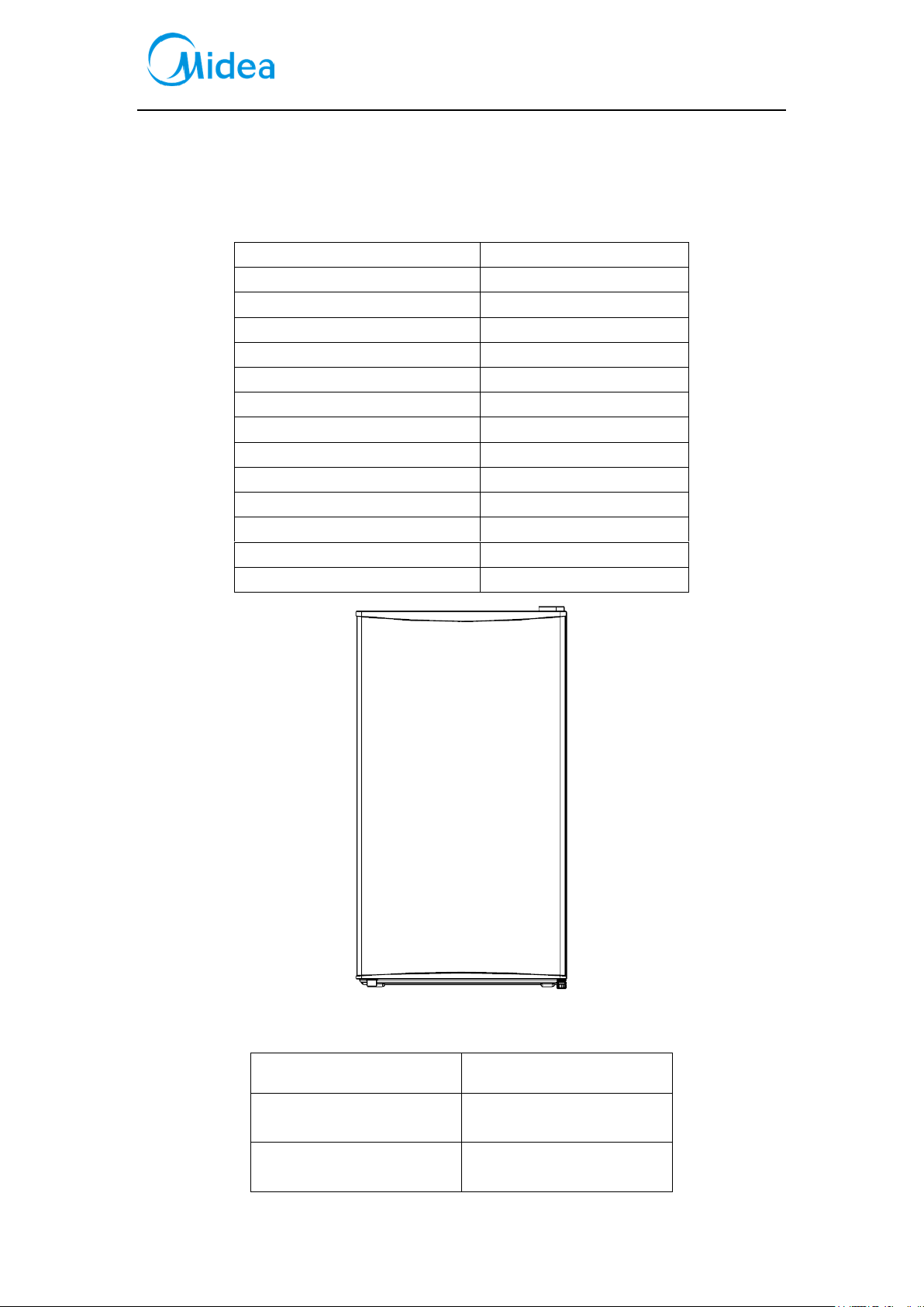
Applicable Model
Model Code
CE-BC93CM-AQ
22031010000982
CE-BC93CM-ST
22031010000245
UR-BC93CM-ST
22031010000482
UR-BC93CM-ST
22031010000561
CE-BC93CM-ST
22031010000242
SR-BC93CM-UT
22031010000243
CE-BC93CM-ST
22031010001261
CE-BC93CM-ST
22031010001381
UR-BC93CM-ST
92031010Z00004
UR-BC93CM-ST
92031010Z00005
UR-BC93CM-ST
92031010Z00006
CE-BC93CM-ST
92031010Z00008
CE-BC93CM-ST
92031010Z00010
(The picture is only for reference, and specific appearance and configuration are subject to the real
product)
Prepared by
R&D: Yng Huiqun
Reviewed by
QA: Wang Tao
SVC: Zhang Kun
Approved by
R&D: Tang Tao
SVC: Guang Taoshuai

Service Manual, 2016-12
2 / 37
Important Safety Notice
The Maintenance Manual is only for the use of maintenance personnel with certain experience and
background in electrical, electronic and mechanical field.
Any attempt to repair main devices may lead to personal injury and property loss.
Manufacturers or distributors are not responsible for the content of the Manual and interpretation
thereof.
Midea Refrigerators
Technical Maintenance Manual
Copyright @2016
All rights reserved. Replication of all or part of the Manual in any forms shall not be allowed without
written approval by the Overseas Sales Corporation of Midea Refrigerators.

Service Manual, 2016-12
3 / 37
Contents
1.SAFETY WARNING CODE ......................................................................................................... 5
1.1WARNING FOR OPERATION SAFETY .................................................................................................. 5
1.2SAFETY INSTRUCTION FOR REFRIGERANT ......................................................................................... 8
2.DESCRIPTION FOR PRODUCT FEATURES ............................................................................ 9
3.INSTALLATION AND COMMISSIONING .............................................................................. 10
3.1HANDLING ..................................................................................................................................... 10
3.2DISASSEMBLY (NONE) .................................................................................................................... 10
3.3 INSTALLATION LOCATION .............................................................................................................. 10
3.4 LEVELING OF THE REFRIGERATOR .................................................................................................. 10
3.5CHANGE THE DOOR OPENING DIRECTION ........................................................................................ 11
3.6 INSTALLATION OF HANDLE(NONE) ................................................................................................ 12
3.7 INSTALLATION OF DOOR LOCK(NONE) ........................................................................................... 12
3.8 ADJUSTMENT TO LEVEL THE DOOR(NONE) .................................................................................... 12
3.9 ADJUSTMENT TO SHELVES(NONE) ................................................................................................. 12
4.TERMS ........................................................................................................................................ 13
4.1 DEFINITION OF MODEL(NONE) ...................................................................................................... 13
4.2LOCATION OF NAMEPLATE .............................................................................................................. 13
5.PRODUCT SPECIFICATION .................................................................................................... 14
5.1 TYPESPECIFICATION(NONE) .......................................................................................................... 14
5.2 ELECTRICAL PARAMETERS ............................................................................................................. 14
5.3REFRIGERATING TEMPERATURE ...................................................................................................... 16
5.4DEFROSTING PARTS(NONE) ............................................................................................................ 16
5.5CIRCUIT DIAGRAM.......................................................................................................................... 16
6.INTERNAL VIEW AND DIMENSION ...................................................................................... 18
6.1MAIN PARTS AND THEIR NAMES ...................................................................................................... 18
6.2EXTERNAL DIMENSION ................................................................................................................... 18
7.REFRIGERATING PIPING SYSTEM AND CIRCULATING ROUTE OF COOLING AIR7.1 REFRIGERATING
PIPING SYSTEM .................................................................................................................................... 21
7.2CIRCULATING ROUTE OF COOLING AIR(NONE)................................................................................ 21
8. DISMANTLING OF PARTS ...................................................................................................... 22
8.1 PARTS ON THE DOOR ...................................................................................................................... 22
8.2 PARTS INSIDE THE REFRIGERATOR ................................................................................................. 22
8.3 LIGHT SYSTEM ............................................................................................................................... 23
8.4AIR DUCT COMPONENTS REFRIGERATINGCHAMBER ........................................................................ 23
8.5AIR DUCT COMPONENTS IN FREEZING CHAMBER AND FAN MOTOR.................................................. 23
8.6EVAPORATOR AND TEMPERATURE SENSING SYSTEM ....................................................................... 23

Service Manual, 2016-12
4 / 37
8.6COMPRESSOR CASE ........................................................................................................................ 24
8.7DISPLAY AND MAIN CONTROL PANEL(NONE) .................................................................................. 26
8.8 BAR COUNTER(NONE) ................................................................................................................... 26
8.9 WATER DISPENSER(NONE) ............................................................................................................ 26
8.10 ICE MAKER(NONE) ...................................................................................................................... 26
9. FUNCTION AND OPERATION ................................................................................................ 27
9.1OPERATION PANEL .......................................................................................................................... 27
9.2TEMPERATURE CONTROL ................................................................................................................ 27
9.3GIVE AN ALARM(NONE) ................................................................................................................. 27
9.4FAILURE CODE AND SOLUTIONS(NONE) ......................................................................................... 27
9.5DEFROST FUNCTION ....................................................................................................................... 27
9.6COMPRESSOR FAN CONTROL(NONE) .............................................................................................. 27
9.7SELF-DIAGNOSIS (NONE) ................................................................................................................ 27
10.CIRCUIT DESCRIPTION ........................................................................................................ 28
10.1 POWER SUPPLY(NONE) ................................................................................................................ 28
10.2 TEST CIRCUIT FOR DOOR SWITCH(NONE) ..................................................................................... 28
10.3 TEMPERATURE TEST CIRCUIT(NONE) ........................................................................................... 28
10.4FREEZER CHAMBER FAN MOTOR CIRCUIT (NONE) ......................................................................... 28
10.5REFRIGERATING CHAMBER FAN MOTOR CIRCUIT (NONE) .............................................................. 28
10.6CONDENSATION FAN CIRCUIT (NONE) .......................................................................................... 28
10.5 FAN MOTOR CIRCUIT OF THE VENTILATION DOOR(NONE) ............................................................ 28
10.6RESISTANCE VALUE OF THE SENSOR (R/T) (NONE) ....................................................................... 28
11.TROUBLESHOOTING METHOD........................................................................................... 29
11.1 NOT COOLING .............................................................................................................................. 29
11.2 NOT WORKING OF COMPRESSOR .................................................................................................. 30
11.3 -THERMOSTAT MALFUNCTION-UNDERCOOLING........................................................................... 31
11.4 LIGHT IS NOT ON .......................................................................................................................... 31
11.5 NOISE .......................................................................................................................................... 32
12. FIGURES AND DETAILS OF REPAIR
PARTS(DOCUMENTS ARE PROVIDED SEPARATELY) .......................................................... 33
12.1FIGURES ....................................................................................................................................... 33
12.2LIST OF PARTS AND COMPONENTS ................................................................................................. 33
13APPENDIX: ................................................................................................................................ 34
13.1ELECTRICAL SCHEMATIC DIAGRAM(NONE) ................................................................................. 34
13.2REFRIGERATOR MAINTENANCE TOOLING AND EQUIPMENT AND MATERIAL ................................. 34
Service Manual, 2016-12
5 / 37
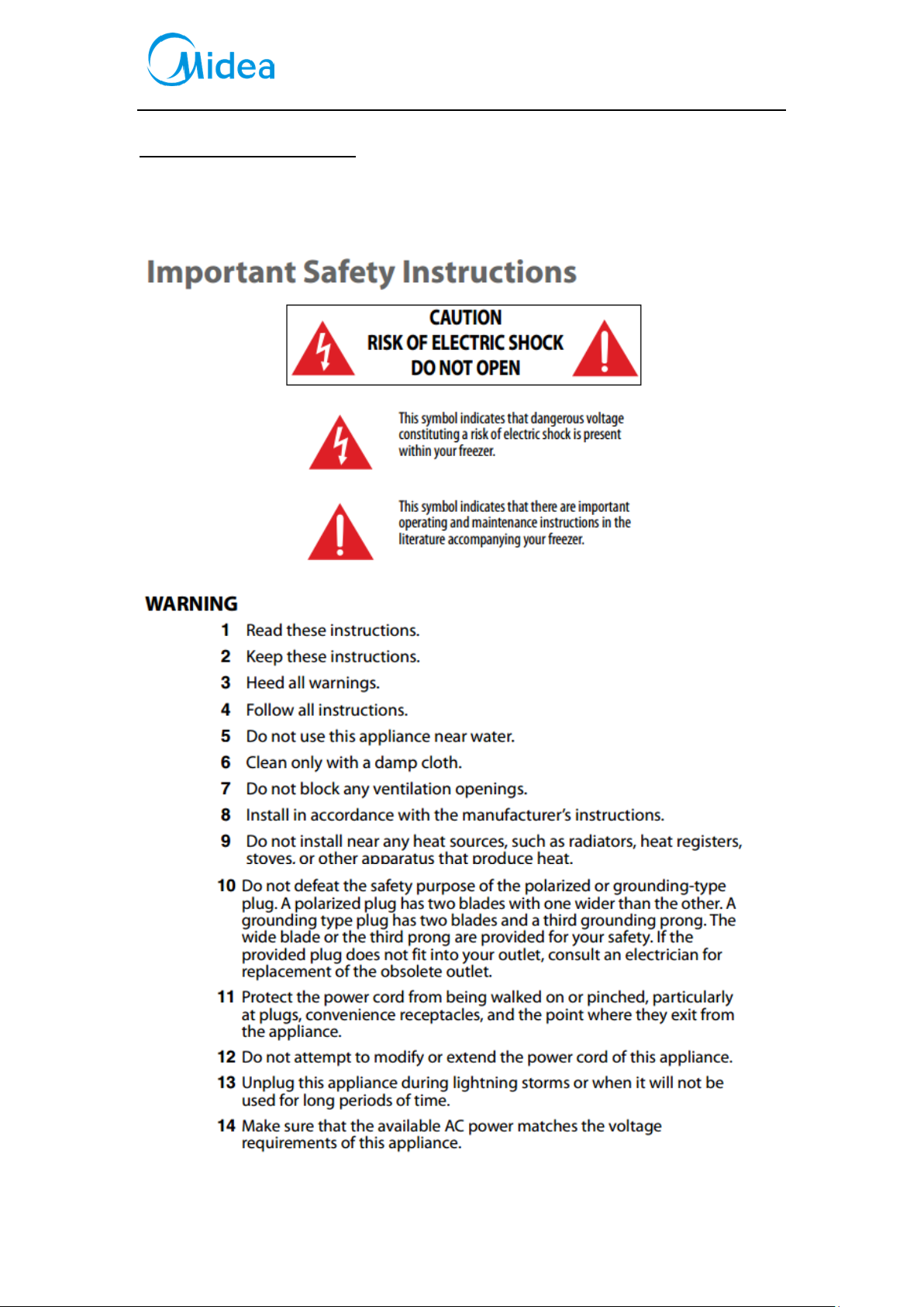
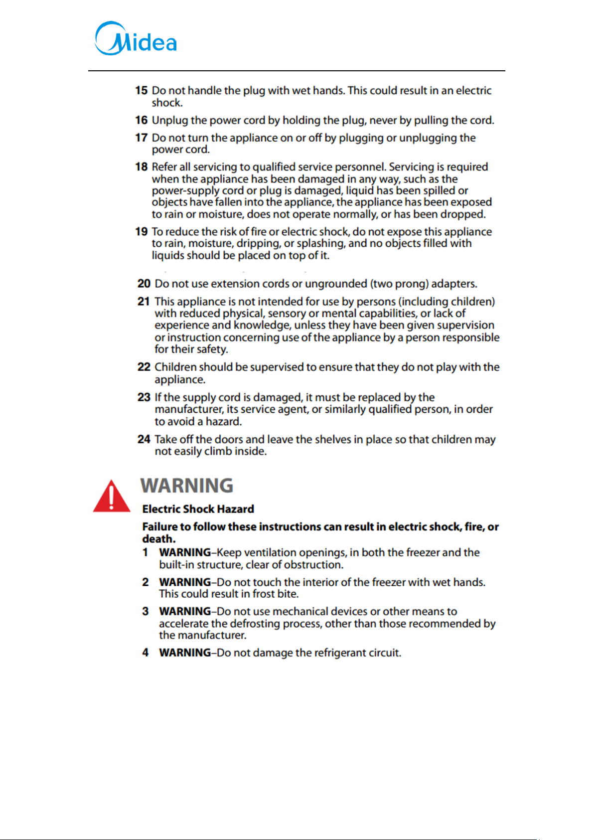
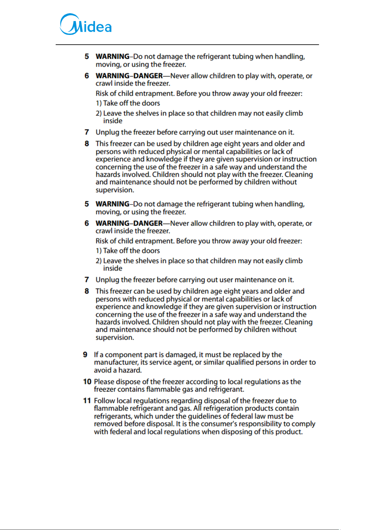
1.Safety Warning Code
1.1Warning for operation safety
Service Manual, 2016-12
6 / 37
Service Manual, 2016-12
7 / 37
Service Manual, 2016-12
8 / 37
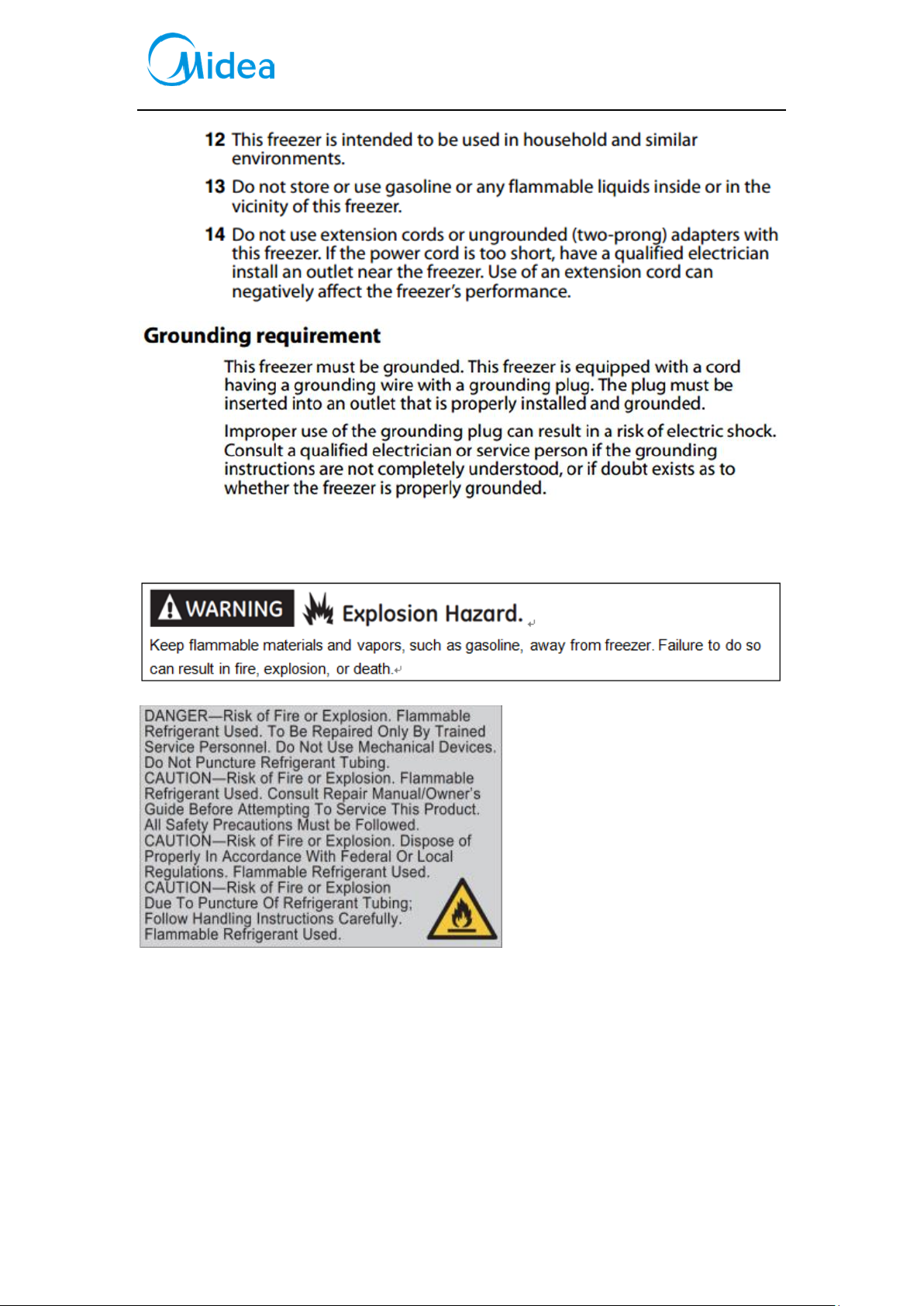
1.2Safety instruction for refrigerant
Service Manual, 2016-12
9 / 37
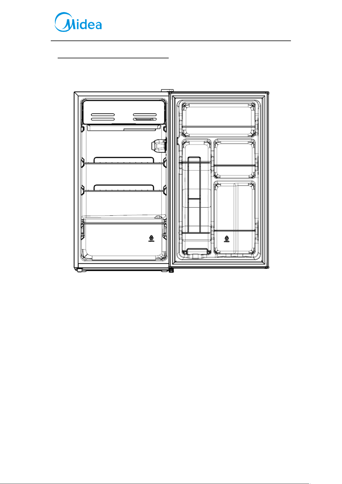
2.Description for product features
This product is provided with following features:
(The picture is only for reference, and specific appearance and configuration are subject to the real
product)
1)Mechanical temperature controlManual defroststeel wire guardrailChange the door opening
direction
Service Manual, 2016-12
10 / 37
3.Installation and commissioning
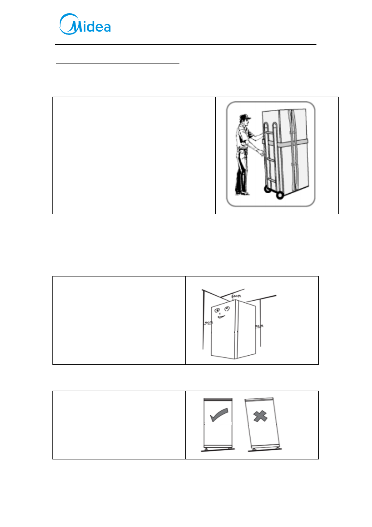
3.1Handling
1) Protecttherefrigeratorinmovingit
Sameasshownasleftphoto,pleasemoveitbyhandcartwi
thcushion
2) Removeallpackingmaterialsandbottomcushion,then
moveintohouseforplacement
3) Aftermovingittoappropriatelocation,waitfor2hoursbe
forepoweron.
3.2Disassembly (None)
The refrigerator door needs to be dismantled if it cannot enter the room in the whole.
3.3 Installation location
Location that is easy for ventilation shall be
chosen to facilitate heat dissipation, enhance
its performance and reduce the energy
consumption.
3.4 Leveling of the refrigerator
If the refrigerator cannot be placed steadily,
adjust the footing to level it.
Service Manual, 2016-12
11 / 37
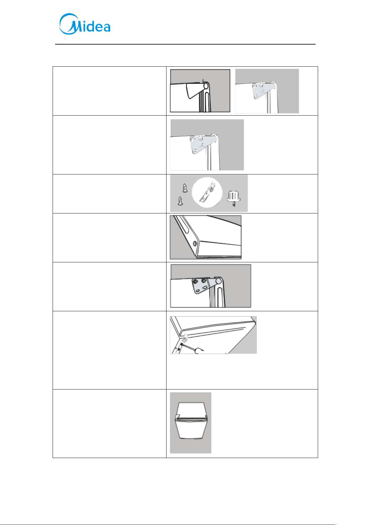
3.5Change the door opening direction
1) Remove the plastic covering from
the top door hinge.
2) Unscrew the two screws from the
bottom bracket. Remove the foot
from opposite side.
3) Place to one side.
4) Slide the Appliance door down
about 15cm and off the top hinge
pin and lift away from the
Appliance.
5) Remove the two screws from top
bracket and replace on the
otherside. You will need to first
remove the plastic caps from the
other side.
6) Slide the Appliance door back on to
the Top hinge, making sure its the
right way up. Screw the bottom
hinge into place on the new side.
Replace the other foot on the other
side. Replace the plastic covering by
clicking back into position on the
door hinge.
7) Check that the door is aligned
horizontally and vertically and that
the seals are closed on all sides
before finally tightening the bottom
hinge.
Re-adjust the levelling feet.

Service Manual, 2016-12
12 / 37
3.6 Installation of handle(None)
3.7 Installation of door lock(None)
3.8 Adjustment to level the door(None)
3.9 Adjustment to shelves(None)
 Loading...