


www.apc.com / www.mgeups.com
Network Shutdown Module V3
User Manual
T H E U N I N T E R R U P T I B L E P O W E R P R O V I D E R
Network Shutdown Module V3 – User Manual – APC # 990-3630 (MGE # 34 003 896 XU / AB)

www.apc.com / www.mgeups.com
Network Shutdown Module V3
User Manual
T H E U N I N T E R R U P T I B L E P O W E R P R O V I D E R
Network Shutdown Module V3 – User Manual – APC # 990-3630 (MGE # 34 003 896 XU / AB)

www.apc.com / www.mgeups.com
Table of Contents
1 |
Introduction to the MGE’s Network Solution ....................................................................... |
4 |
|
|
1.1 |
Overview ............................................................................................................................................... |
4 |
|
1.2 |
Monitoring the UPSs over the network.................................................................................................. |
5 |
|
1.3 |
Protecting the computers / servers ....................................................................................................... |
6 |
|
1.4 |
Connecting the UPS.............................................................................................................................. |
7 |
|
1.4.1 |
Connecting to the Network ............................................................................................................................ |
7 |
|
1.4.2 |
Select Network Architecture .......................................................................................................................... |
7 |
|
1.4.3 |
Network Performances.................................................................................................................................. |
8 |
2 |
Installation............................................................................................................................... |
9 |
|
|
2.1 |
Hardware Pre-requisites (Electrical and Network Connections)........................................................... |
9 |
|
2.2 |
Software Installation Pre-requisites..................................................................................................... |
10 |
|
2.2.1 |
On the System Hosting « Network Shutdown Module V3 » ........................................................................ |
10 |
|
2.2.2 |
On the System that Displays Web-based Graphical User Interface ............................................................ |
11 |
|
2.3 |
Quick Start........................................................................................................................................... |
12 |
|
2.4 |
Software Installation Procedure .......................................................................................................... |
13 |
|
2.5 |
Application deployment and silent installation (advanced) ................................................................. |
15 |
|
2.6 |
Uninstalling the Network Shutdown Module....................................................................................... |
15 |
3 |
Minimal configuration steps................................................................................................ |
16 |
|
|
3.1 |
Introduction.......................................................................................................................................... |
16 |
|
3.2 |
The IP address of the UPS that powers your server........................................................................... |
16 |
|
3.3 |
Users accounts configuration.............................................................................................................. |
18 |
4 |
Use ......................................................................................................................................... |
19 |
|
|
4.1 |
Monitoring the server and the UPS(s)................................................................................................. |
19 |
|
4.1.1 |
Local access ............................................................................................................................................... |
19 |
|
4.1.2 |
Remote access ........................................................................................................................................... |
19 |
|
4.2 |
System and UPS event log ................................................................................................................. |
22 |
|
4.3 |
UPS Events list.................................................................................................................................... |
22 |
|
4.4 |
Test the communication with the UPS ................................................................................................ |
24 |
|
4.4.1 |
Simple Tests ............................................................................................................................................... |
24 |
|
4.4.2 |
Advanced tests............................................................................................................................................ |
25 |
|
4.5 |
Start and stop the Shutdown Module (advanced)............................................................................... |
25 |
5 |
Other Configuration possibilities........................................................................................ |
26 |
|
|
5.1 |
Introduction.......................................................................................................................................... |
26 |
|
5.2 |
Configure system parameters ............................................................................................................. |
26 |
|
5.3 |
Shutdown Configuration...................................................................................................................... |
27 |
|
5.4 |
Checking for Upgrades........................................................................................................................ |
29 |
|
5.5 |
Events and actions (advanced configuration) ..................................................................................... |
30 |
6 |
Multi-UPS Systems............................................................................................................... |
31 |
|
|
6.1 |
Caution ................................................................................................................................................ |
31 |
|
6.2 |
Presentation ........................................................................................................................................ |
31 |
|
6.3 |
Create a multi-UPS configuration........................................................................................................ |
34 |
7 |
Appendix ............................................................................................................................... |
35 |
|
|
7.1 |
Single UPS Mode compatibility ........................................................................................................... |
35 |
|
7.1.1 |
Card/Proxy compatibility.............................................................................................................................. |
35 |
|
7.1.2 |
UPSs compatibility ...................................................................................................................................... |
35 |
|
7.2 |
Multi-UPS Mode Compatibility list ....................................................................................................... |
35 |
|
7.2.1 |
Caution........................................................................................................................................................ |
35 |
|
7.2.2 |
« simple » configurations............................................................................................................................. |
35 |
|
7.2.3 |
Simple associations of the previous configurations..................................................................................... |
37 |
|
7.2.4 |
Configurations NOT supported.................................................................................................................... |
38 |
|
7.3 |
Examples of Multi UPS configurations ................................................................................................ |
39 |
|
7.4 |
Multi-UPS Systems and Event Management...................................................................................... |
39 |
|
7.5 |
Application deployment and silent installation..................................................................................... |
40 |
T H E U N I N T E R R U P T I B L E P O W E R P R O V I D E R |
|
||
|
|
||
Network Shutdown Module V3 – User Manual - APC # 990-3630 (MGE # 34 003 934 XU / AB) |
Page 2/66 |
||

www.apc.com / www.mgeups.com
|
7.5.1 |
Introduction ................................................................................................................................................. |
40 |
|
7.5.2 |
Customized installation package................................................................................................................. |
41 |
|
7.5.3 |
Install the Shutdown Module in silent mode ................................................................................................ |
42 |
|
7.5.4 |
Advanced installation options...................................................................................................................... |
43 |
|
7.6 |
Single UPS Shutdown Sequence........................................................................................................ |
44 |
|
7.7 |
Multi UPS shutdown sequence (example with Static Transfer Switch) .............................................. |
46 |
|
7.8 |
Additional information on events and actions...................................................................................... |
47 |
|
7.8.1 |
Action settings Tab...................................................................................................................................... |
47 |
|
7.8.2 |
Events Tab.................................................................................................................................................. |
52 |
|
7.8.3 |
Test tab ....................................................................................................................................................... |
54 |
|
7.8.4 |
The action parameters (execute and send email) ...................................................................................... |
55 |
|
7.8.5 |
Software utilities .......................................................................................................................................... |
55 |
|
7.9 |
FAQ and Error messages.................................................................................................................... |
58 |
8 |
Glossary ................................................................................................................................ |
61 |
|
9 |
Acknowledgements.............................................................................................................. |
62 |
|
|
9.1 |
SQLite.................................................................................................................................................. |
62 |
|
9.2 |
Pi3Web................................................................................................................................................ |
62 |
|
9.3 |
PHP ..................................................................................................................................................... |
62 |
|
9.4 |
OpenSSL............................................................................................................................................. |
63 |
|
9.5 |
Lighttpd................................................................................................................................................ |
65 |
|
9.6 |
WxWidget ............................................................................................................................................ |
65 |
|
|
|
|
T H E U N I N T E R R U P T I B L E P O W E R P R O V I D E R
Network Shutdown Module V3 – User Manual - APC # 990-3630 (MGE # 34 003 934 XU / AB) Page 3/66
www.apc.com / www.mgeups.com
1 Introduction to the MGE’s Network Solution
1.1Overview
MGE’s Network Solution:
ωprovides information on events concerning the supply of power to the computers connected to your computer network,
ωcarries out automatic shutdown of computer systems,
ωmonitors and controls all the UPSs connected to the network.
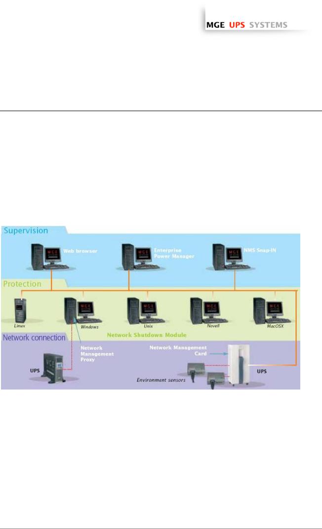
As illustrated in the picture below, MGE Network Solution provides these 3 main functions:
ωsupervising the UPSs over the Network,
ωprotecting the computers,
ωconnecting the UPS to the Network.
The functions of MGE’s Network offering
T H E U N I N T E R R U P T I B L E P O W E R P R O V I D E R
Network Shutdown Module V3 – User Manual - APC # 990-3630 (MGE # 34 003 934 XU / AB) Page 4/66
www.apc.com / www.mgeups.com
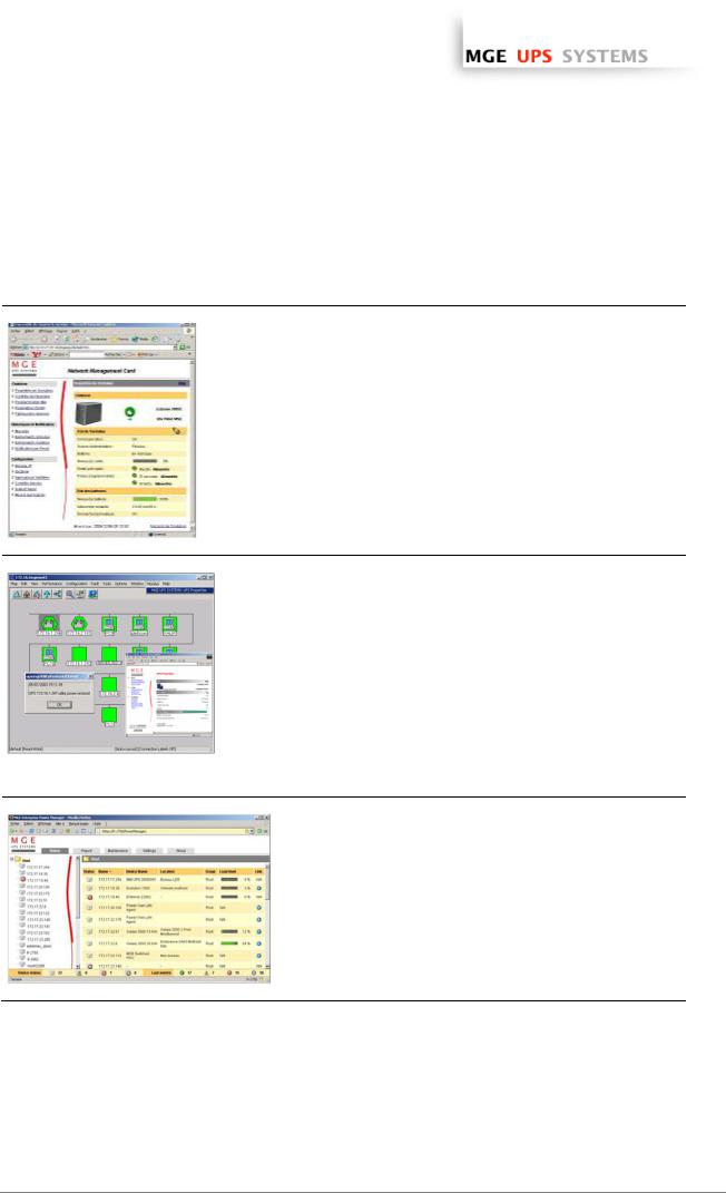
1.2Monitoring the UPSs over the network
Depending on your needs, you can either use:
ωyour Internet browser to monitor each UPS, as
Management Proxy, Management Card and Shutdown Module include a Web server.
ωyour company’s standard Network Management System:
>HP-Openview,
>CA Unicenter,
>HP Insight Manager,
>IBM Tivoli Netview,
>…
To simplify integration of MGE UPSs with these
NMS, you can use one of the Network
Management System Kits for MGE devices.
These kits are available on Management Pac 2
CD-Rom (ref 66923).
ωthe MGE supervisor "Enterprise Power Manager"
>5 nodes (free),
>50 nodes (ref 66923),
>Unlimited (ref 66924).
T H E U N I N T E R R U P T I B L E P O W E R P R O V I D E R
Network Shutdown Module V3 – User Manual - APC # 990-3630 (MGE # 34 003 934 XU / AB) Page 5/66
www.apc.com / www.mgeups.com
1.3Protecting the computers / servers
The Network Shutdown Module installed on each of the servers to be protected performs this function. Note that the Shutdown Module is available on several Operating Systems.
The Shutdown modules:
ωcontinuously wait for information from the Mgt. Proxy or Mgt. Card connected to the MGE UPS.
ωwarns administrators and users if AC power fails and proceeds with graceful system shutdown before the end of battery backup power is reached.
New functions:
The latest version V3 the Network Shutdown Module:
ωoffers a remote supervision interface through any web browser (with a secured SSL/HTTPS connection enabled by default),
ωmanages multi UPS redundant configurations (see “Multi-UPS systems” chapter )
>Several UPSs in parallel
>2 UPSs in Hot standby (or serial) redundancy
>2 redundant UPSs through Static Transfer Switch
>UPSs powering a server with multiple power supplies
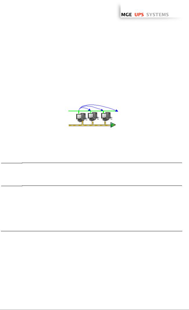
3 UPSs in parallel powering several servers
ωmanages switchable outlets
With this version you can trigger shutdown sequences with switchable outlets.
A UPS that powers servers with load-shedding function
T H E U N I N T E R R U P T I B L E P O W E R P R O V I D E R
Network Shutdown Module V3 – User Manual - APC # 990-3630 (MGE # 34 003 934 XU / AB) Page 6/66
www.apc.com / www.mgeups.com
1.4Connecting the UPS
1.4.1Connecting to the Network
This function can be performed either through network Cards inserted in the UPS (Network Management Card) or through a software “agent” running on a nearby PC that is called the Network Management Proxy. Note that the Network Management Proxy is available only on Windows.
The Network Management Card or Proxy:
ω manages communication with the UPS (as well as local protection of the machine on which Proxy is installed),
ωperiodically accesses the information concerning the UPS,
ωmakes this information available to the connected applications (Network Shutdown Modules, Web Browser, Network Management Systems, Enterprise Power Manager)
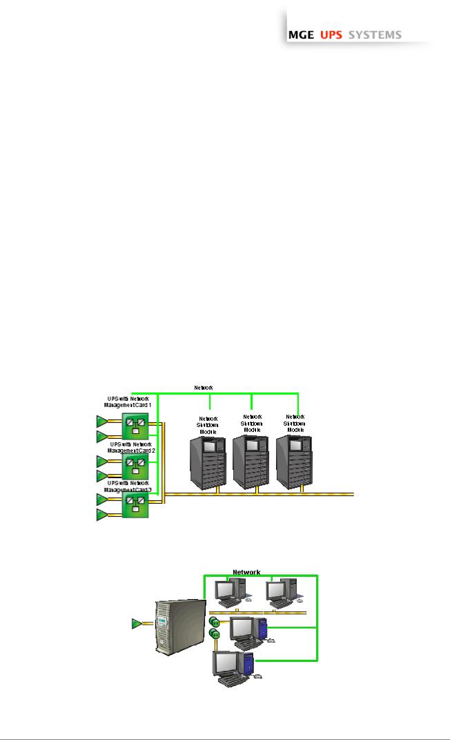
1.4.2Select Network Architecture
Below are two software and hardware architectures showing how MGE UPSs can protect several computers. These typical examples are intended to assist you in designing your own architecture.
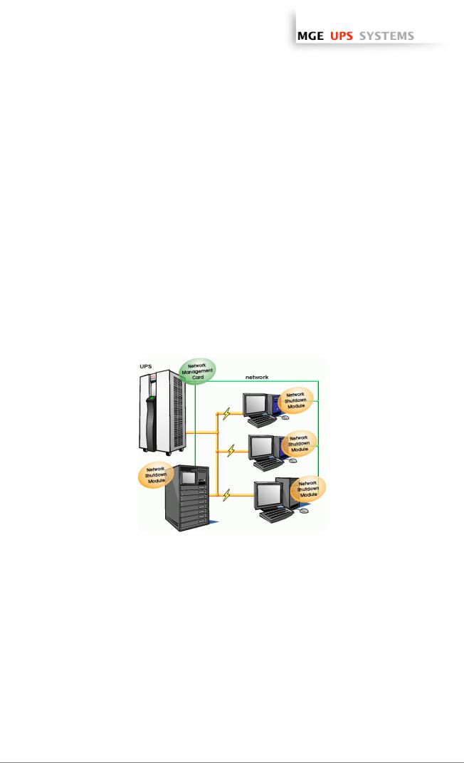
Connection with Network Management Card
On the diagram above, the following two types of connections are required:
ωthe electrical power cables,
ωthe TCP/IP communication network.
T H E U N I N T E R R U P T I B L E P O W E R P R O V I D E R
Network Shutdown Module V3 – User Manual - APC # 990-3630 (MGE # 34 003 934 XU / AB) Page 7/66
www.apc.com / www.mgeups.com
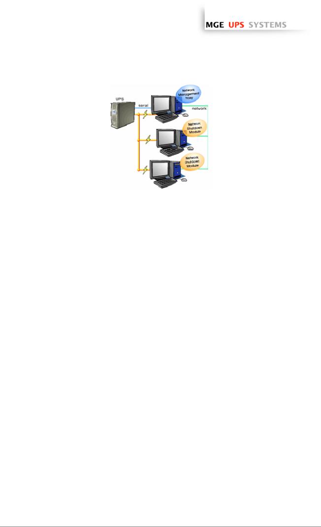
Connection with Network Management Proxy
On the diagram above, three types of connections are required:
ωa point-to-point link (serial or USB),
ωthe electrical power cables,
ωthe TCP/IP communication network.
1.4.3Network Performances
The Network Management Card is designed to support a maximum of:
ω35 or 50 Network Shutdown Module connections in standard secure mode
Network Management Proxy, installed on a dedicated server, with at least 500 MB of Ram and a 1 GHz CPU, is designed to support a maximum of:
ω250 Network Shutdown Module connections in standard secure mode.
T H E U N I N T E R R U P T I B L E P O W E R P R O V I D E R
Network Shutdown Module V3 – User Manual - APC # 990-3630 (MGE # 34 003 934 XU / AB) Page 8/66
www.apc.com / www.mgeups.com
2 Installation
Note: This user manual only applies to Network Shutdown Module V3. For previous versions of Network Shutdown Module V2.x, please read the HTML on line manual.
2.1Hardware Pre-requisites (Electrical and Network Connections)
Connection steps
Before connecting the UPS, you must first decide on a software and hardware architecture.
Before installing the MGE Network Solution, the UPS must be set up as indicated in the steps below.
ωShut down the computers to be protected by the UPS.
ωConnect the UPS to a wall outlet. (For UPSs above 3kVA, please refer to the UPS installation manual).
ωConnect the power cord of each computer to an outlet on the UPS. (For UPSs above 3kVA, please refer to the UPS installation manual).
ωHow to connect UPS / proxy or card / network:
>If the Mgt. Proxy is used, connect the serial or USB port on the computer and on the UPS.
>If a Network Management Card is used, insert the optional card in the UPS and connect the UPS to the computer network.
ωStart the MGE UPS, then the computers.
ωSetting up the protection
>If the Mgt. Proxy is used install it on the one machine directly connected to the UPS.
>If a Network Management Card is used, it must be set up (see the Mgt. Card's user manual).
ωInstall Network Shutdown Module on all the other machines that are to be protected by the UPS (supplied with UPS battery backup power).
Note: The Mgt. Proxy manages protection of the machine on which it is installed.
T H E U N I N T E R R U P T I B L E P O W E R P R O V I D E R
Network Shutdown Module V3 – User Manual - APC # 990-3630 (MGE # 34 003 934 XU / AB) Page 9/66
www.apc.com / www.mgeups.com
2.2Software Installation Pre-requisites
2.2.1On the System Hosting « Network Shutdown Module V3 »
2.2.1.1 Windows Compatibilities:
Network Shutdown Module V3 Windows is compatible and has been tested with: ω Windows (x86)
ω Windows (x86)
ω Windows (Xeon 64)
ω Windows (AMD Opteron)
ω Windows (Intel Xeon)
2.2.1.2 Linux Compatibilities:
Network Shutdown Module V3 Linux is compatible and has been tested with:
ω Linux (x86) |
Debian GNU Linux: |
Sarge, Etch, |
|
SUSE/Novell: |
SLES 10, |
|
Redhat Enterprise Linux: |
RHEL 3 & RHEL4 |
|
Ubuntu: |
Dapper |
The Linux package is based on standard Linux mechanisms and therefore can be installed and used with other Linux distributions. Feedbacks / test or bug reports are welcome at MGE UPS SYSTEMS Support. The following list is not exhaustive. Network Shutdown Module V3 should be compatible with:
ω Linux (x86) |
Debian GNU Linux: |
Testing, |
|
SUSE/Novell: |
SLES 9, SLED 9, SLED 10, openSUSE 10.x |
|
Redhat Enterprise Linux: |
Fedora core 4, 5, 6 |
|
Ubuntu: |
Edgy, Feisty |
|
Others: |
VMWare ESX3, IPCop |
2.2.1.3 Standby configuration (Windows):
In Configuration Panel -> Power Option properties:
ωYou must unselect the Standby configuration of your Operating System to be compliant with the Network Shutdown Module. With the standby configuration checked your system is not protected.
ωIf you want to save energy, please prefer the hibernate feature.
2.2.1.4 Broadcast Message configuration (Windows):
If the “Broadcast administrator messages / Broadcast user messages ” function is activated, on Network Shutdown Module, you have to check that the “Messenger” Service is started.
This service is mandatory to use the broadcast messages on Windows.
2.2.1.5 Firewall configuration(Windows & Linux):
If you use Windows XP with Service Pack 2 or Windows 2003 with Service Pack 1:
(Optional) To enable a remote access for supervision and configuration you will have to open the following ports of the Windows Firewall:
T H E U N I N T E R R U P T I B L E P O W E R P R O V I D E R
Network Shutdown Module V3 – User Manual - APC # 990-3630 (MGE # 34 003 934 XU / AB) Page 10/66

www.apc.com / www.mgeups.com
ω4679 MGESupervision
ω4680 MGEManagement (access through SSL)
These ports are reserved for MGE UPS SYSTEMS at IANA (Internet Assigned Numbers Authority, http://www.iana.org/).
Proceed as follows:
ωEnter into Start -> Parameters-> Configuration Panel -> Windows Firewall
ωIn the Exception tab, click on «add a port »
ωEnter the name « MGESupervision » the number « 4679 » the protocol « TCP »
ωApply and perform the same operations for the next port
ωEnter the name « MGEManagement » the number « 4680 » the protocol « TCP »
ωApply
If you use a Firewall with all ports closed by default:
To enable communication between Network Shutdown Module and Network Management Card:
ωPort 80 must be opened as a destination port (for output) on the machine hosting Network Shutdown Module.
2.2.2On the System that Displays Web-based Graphical User Interface
Important:
The Network Shutdown Module graphical interface can be accessed remotely using a simple Web browser. Access to this interface is secured through SSL connection (default configuration) and must also be secured through Login & password.
The Network Shutdown Module graphical interface has been tested with:
ωMozilla Firefox 1.5 or 2.0 is recommended for better performance. (Firefox is mandatory for Linux)
ωMicrosoft Internet Explorer V6, V7
Note: For the Web browser, we advise you against the use of the highest security level. Some configuration screens are not useable.
Javascript and Cookies must be authorized for the selected security level.
T H E U N I N T E R R U P T I B L E P O W E R P R O V I D E R
Network Shutdown Module V3 – User Manual - APC # 990-3630 (MGE # 34 003 934 XU / AB) Page 11/66
www.apc.com / www.mgeups.com
2.3Quick Start
To install the Network Shutdown Module in 5 minutes, please perform the following steps on a machine running Windows 2000 / XP / 2003 / Vista or Linux:
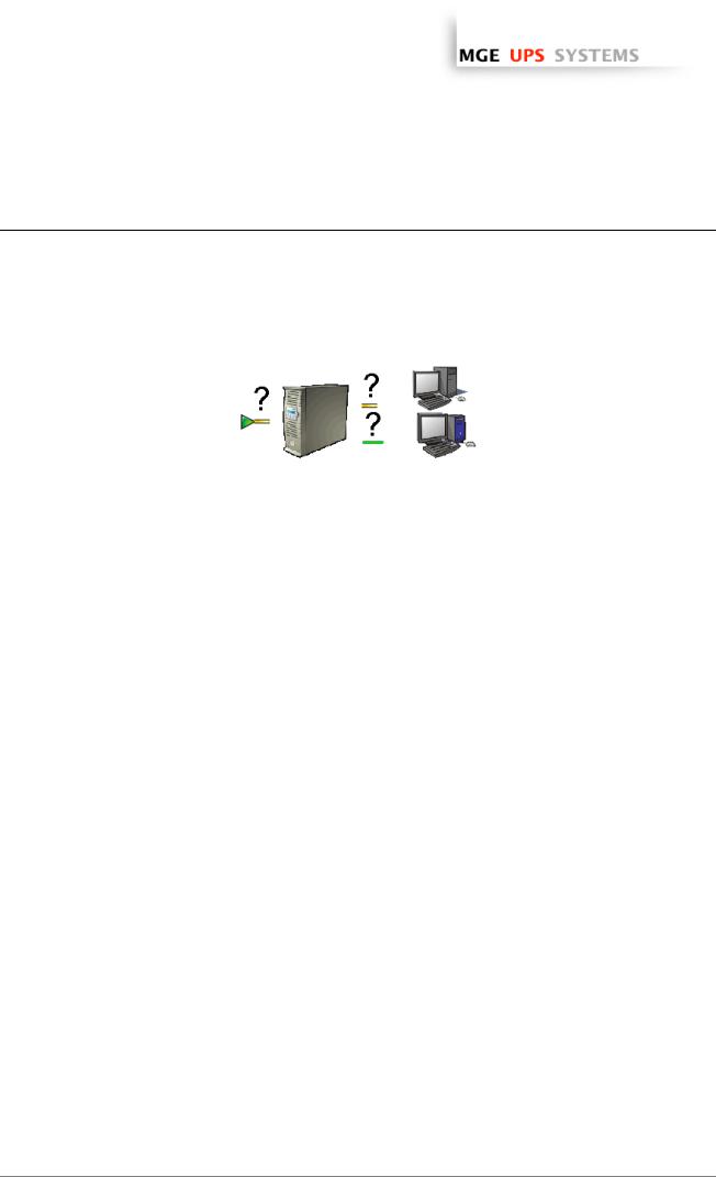
ωStep 1 (Pre-requisites)
Check that following connections are operational:
>the electrical connection between the UPS and the server to protect
>the network connection between the UPS and the Network Management Card (or Proxy).
ωStep 2 (Optional) and only for Windows Vista, XP with SP 2 or Windows 2003 with SP 1
To enable the configuration and supervision remote access, Network Shutdown Module needs the 4679 and 4680 ports to be opened in the Windows Firewall.
ωStep 3 (Software Installation)
On a Windows 2000 / XP / 2003 / Vista or Linux machine, execute the “Network Shutdown Module” package under an administrator account.
ωStep 4 (Configuration)
>In the Configuration->Power devices screen,
Enter the default Login «MGEUPS» and default Password «MGEUPS» Then click on the Add button and
Enter the hostname or the IP address of the Network Management Card (or Proxy). Save your configuration
>In the Configuration->Users window configure your password (recommended)
>For the multi-UPS configurations, please refer to chapter 6
ωStep 5 (Operation)
You can now supervise the UPS state and the information concerning the protected server
T H E U N I N T E R R U P T I B L E P O W E R P R O V I D E R
Network Shutdown Module V3 – User Manual - APC # 990-3630 (MGE # 34 003 934 XU / AB) Page 12/66

www.apc.com / www.mgeups.com
2.4Software Installation Procedure
This section informs on how to install Network Shutdown Module to protect the computer system.
Before starting the installation:
ωit is necessary first to install a Network Management Card in the UPS or the Mgt. Proxy on a server.
ωmake sure you have the necessary administrator rights to install Network Shutdown Module (for Windows and Linux).
ωit is assumed that you are aware of the installation prerequisites.
 Follow these steps to install Network Shutdown Module in interactive (graphical) mode:
Connect to the MGE UPS SYSTEMS download area at http://www.mgeups.com/download/menu.htm. Follow the instructions to download Network Shutdown Module
or insert the Solution-Pac 2 CD-ROM (/HF).
For Windows: From CD ROM:
ωAt the first navigator screen select "Network Solutions" and follow the instructions
|
From the Web: |
|
ω Execute the downloaded package. |
|
From CD ROM: |
For Linux: |
|
|
ω Mount your CD-ROM (ex: /mnt/cdrom) |
|
ω Open Default.htm from your internet browser to discover the solutions and select |
|
"Network Solutions". |
|
ω Follow the instructions |
From the web:
ωDownload and save the file to your computer.
ωAuthorize the execution right on the downloaded package (through graphical interface) or execute the command : chmod 755 nsm_linux_xx_3_xx_xx.run
ωTo install execute the package (double click)
ωIf necessary enter the root password
ωFollow the instructions
ωChoose the installation language. The selected language will correspond to the one of the installed product.
ωRead and accept the License Agreement for MGE UPS SYSTEMS Software.
ωChoose the installation directory of the Network Shutdown Module.
>Windows default value is C:\Program Files\MGE\NetworkShutdownModule
> Linux default value is |
/usr/local/MGE/NetworkShutdownModule |
ωComplete the installation.
ωAfter the installation,
>In the Configuration-> Power device screen,
Enter the default Login «MGEUPS» and default Password «MGEUPS» Then click on the Add button and
Enter the IP address of the Network Management Card (or Proxy). Save your configuration
T H E U N I N T E R R U P T I B L E P O W E R P R O V I D E R
Network Shutdown Module V3 – User Manual - APC # 990-3630 (MGE # 34 003 934 XU / AB) Page 13/66
www.apc.com / www.mgeups.com
Configuration of the communication parameters
ωConfigure your password (recommended)
ωFor multi-UPS systems, please refer to the chapter "Multi UPS systems" .
ωThe Network Shutdown Module is now configured by default. You can anyway customize the Network Shutdown Module and for example configure your password (recommended).
ωThe installed components are automatically started.
ωIt is possible to test Network Shutdown Module.
ωThe protection function is now active on the computer and will be run automatically each time the computer is started.
 Follow these steps to install Network Shutdown Module in console mode:
ωFor Linux, if the server doesn’t have the graphical layer installed, you have to use the specific package called nsm_linux-cli_xxx.run
ωLogin as root in a terminal
ωThen install the Network Shutdown Module in silent mode
Note : You can configure the Network Shutdown Module either:
ωthrough the silent mode parameters (e.g.)
./<FileName> -install –silent –agentName ‘172.17.1.2’
ωthrough remote access
T H E U N I N T E R R U P T I B L E P O W E R P R O V I D E R
Network Shutdown Module V3 – User Manual - APC # 990-3630 (MGE # 34 003 934 XU / AB) Page 14/66
www.apc.com / www.mgeups.com
2.5Application deployment and silent installation (advanced)
After customizing the Network Shutdown Module configuration (name or IP address of Network Management Card/Proxy, events and actions, etc.), you can build a Network Shutdown Module installation package that contains your specific configuration.
You can then deploy this Network Shutdown Module configuration on other machines that have the same operating system.
Network Shutdown Module application deployment
Refer to the appendix “Application deployment and silent installation”
2.6 Uninstalling the Network Shutdown Module
Windows:
Linux:
ωThe shortcut MGE UPS SYSTEMS -> Network Shutdown Module->Uninstall is used to
uninstall Network Shutdown Module. or
ωIn the Control panel, you can also run the Add/remove programs command and select the Network Shutdown Module program.
ωThe KDE shortcut K:-> MGE UPS SYSTEMS -> Network Shutdown Module->Uninstall
is used to uninstall Network Shutdown Module.
ωThe Gnome shortcut Applications-> MGE UPS SYSTEMS -> Network Shutdown Module->Uninstall is used to uninstall Network Shutdown Module.
ωIn console mode, you can execute <Installation directory>/packaging/nsmInstaller – uninstall
<Installation directory> default value is /usr/local/MGE/NetworkShutdownModule/
T H E U N I N T E R R U P T I B L E P O W E R P R O V I D E R
Network Shutdown Module V3 – User Manual - APC # 990-3630 (MGE # 34 003 934 XU / AB) Page 15/66
www.apc.com / www.mgeups.com
3 Minimal configuration steps
3.1Introduction
In this chapter we describe the basic and minimal configuration steps that must be performed before using the Network Shutdown Module.
The other and optional configuration possibilities are described later.
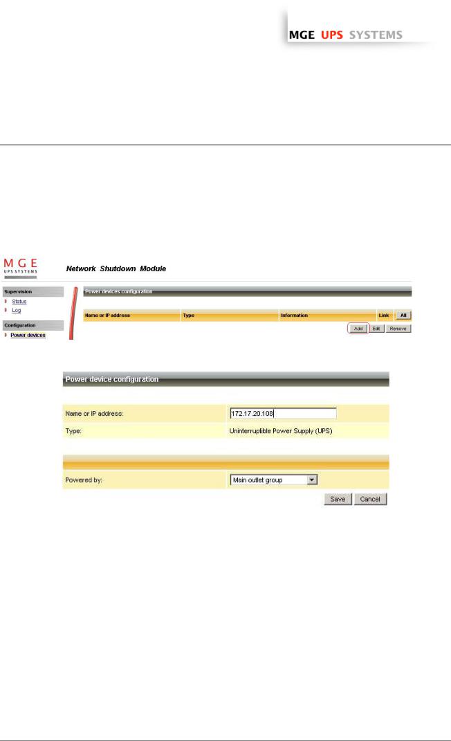
3.2The IP address of the UPS that powers your server.
In the Configuration -> Power device screen, click on the Add button
Adding a power device
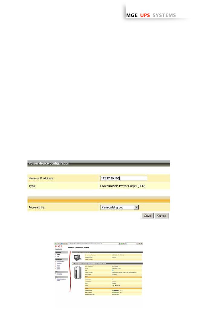
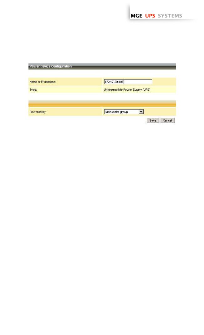
Then following screen appears:
Power device settings
From this screen, you can define the following parameters:
ωNetwork Name or IP address of the Network Management Card / Proxy. This parameter must correspond to the UPS that powers your machine.
ωThe UPS Outlet that powers the server
Powershare outlets and load shedding:
You have the possibility in this page to configure the electrical dependency between one of the UPS switchable plugs and the server hosting Network Shutdown Module.
This function is useful for the servers that must be first shut down during the autonomy sequence.
T H E U N I N T E R R U P T I B L E P O W E R P R O V I D E R
Network Shutdown Module V3 – User Manual - APC # 990-3630 (MGE # 34 003 934 XU / AB) Page 16/66

www.apc.com / www.mgeups.com
Load shedding configuration on UPS powershare outlets
Remark:
This load shedding function is not available if the UPS doesn’t have any switchable outlet.
Note:
For multi-UPS configurations, you have the possibility to enter several names or IP addresses (using the [Add] button). For these advanced configurations, please refer to the Chapter « Multi – UPS systems ».
T H E U N I N T E R R U P T I B L E P O W E R P R O V I D E R
Network Shutdown Module V3 – User Manual - APC # 990-3630 (MGE # 34 003 934 XU / AB) Page 17/66
www.apc.com / www.mgeups.com
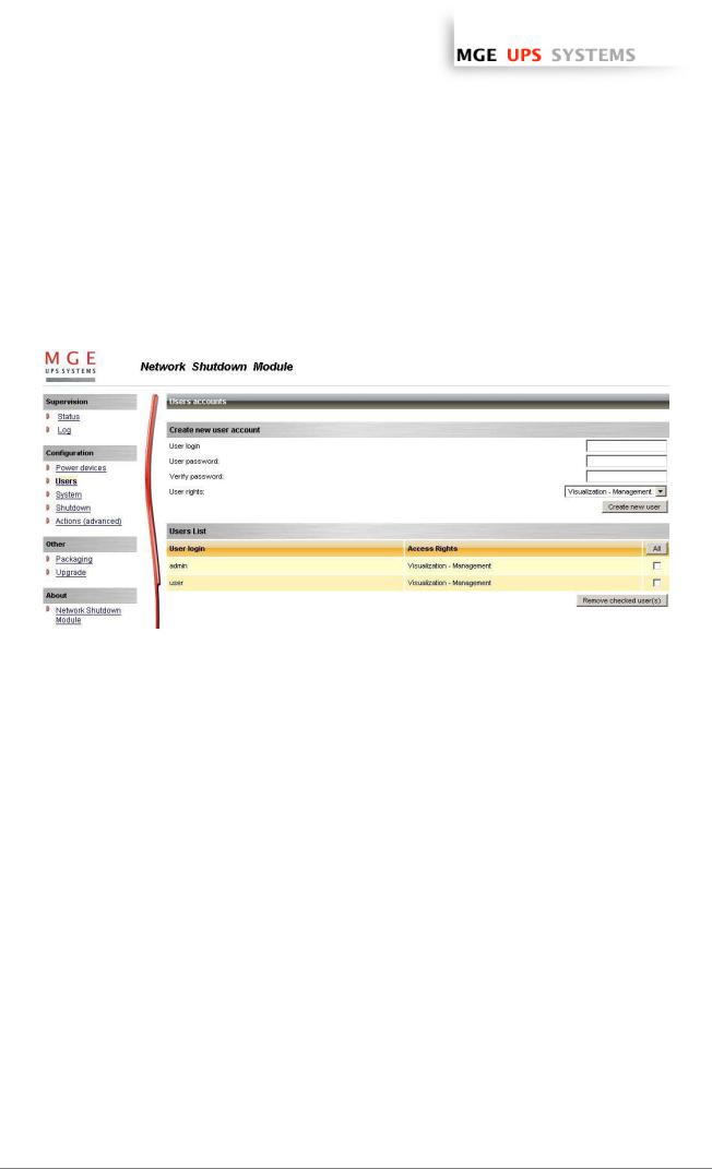
3.3Users accounts configuration
Click on the Users item of the Configuration section on the left menu.
The default Login «MGEUPS» and default Password «MGEUPS» with Visualization – Management rights.
Note : For security reasons we advise you to remove this default login and to create a new login with new access password.
User accounts configuration
You can configure several user accounts.
To add a user account:
ωenter the User Login and the User password (twice),
ωselect the User’s Rights level. The following levels are available: Visualization – Management (the user will be able to access all the sections)
Visualization (the user will only access to the Supervision (*) and the About sections)
ωclick on the Create new user button
(*) Remove logs function in UPS logs panel is only functional with Visualization – Management user's right.
T H E U N I N T E R R U P T I B L E P O W E R P R O V I D E R
Network Shutdown Module V3 – User Manual - APC # 990-3630 (MGE # 34 003 934 XU / AB) Page 18/66
www.apc.com / www.mgeups.com
4 Use
4.1Monitoring the server and the UPS(s)
4.1.1Local access
From the system where the Network Shutdown Module is installed,
ωYou can use the following shortcut:
For Windows: Start -> Programs -> MGE UPS SYSTEMS -> Network Shutdown Module -> Supervision For Linux (KDE): K-> MGE UPS SYSTEMS -> Network Shutdown Module -> Supervision
For Linux (Gnome): Applications -> MGE UPS SYSTEMS -> Network Shutdown Module -> Supervision
ωYou can also use the icon in the task bar:
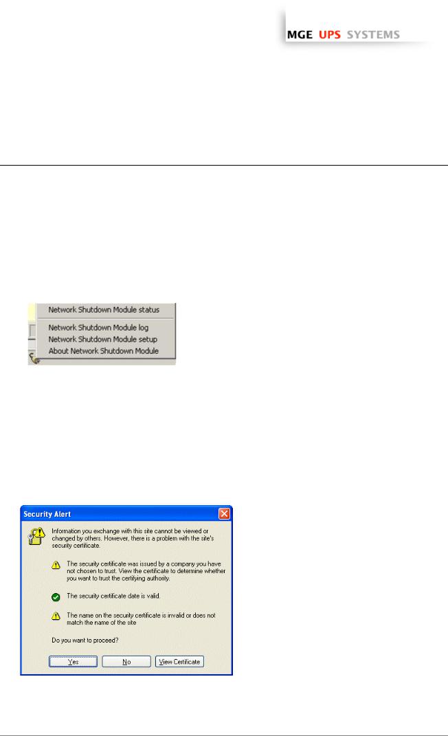
To access to this interface:
ωDouble-click on the icon or
ωRight click the icon in the task bar to access to the item “Network Shutdown module Status”
4.1.2Remote access
ωFrom a remote machine, you can type the following URL in a Web browser for > secured SSL access:
https://< name or IP address of computer hosting NSM>:4680/mgeups/ > or for non secured access:
http://< name or IP address of computer hosting NSM>:4679/mgeups/
Note: The Web server is “case sensitive” for the URL.
ωAccept the SSL Certificate (by clicking on Yes)
Accepting the SSL Certificate
To install the certificate on IE7 for Vista, you need to perform the following steps:
>Run IE as an administrator (Right-click the desktop icon)
>Visit the NSM site.
>Click through the certificate error
>Click the "Certificate Error" button in the address bar.
>Click View Certificate
>Click Install Certificate
>Unlike on XP, you must click the “Place all certificates in the following store” radio button, and choose the “Trusted Root Certification Authorities” store. If you don’t do this, the certificate goes in your personal store, and it isn’t trusted by IE.
T H E U N I N T E R R U P T I B L E P O W E R P R O V I D E R
Network Shutdown Module V3 – User Manual - APC # 990-3630 (MGE # 34 003 934 XU / AB) Page 19/66
 Loading...